EP2757696A1 - Waveform modulation for rotorcraft. - Google Patents
Waveform modulation for rotorcraft. Download PDFInfo
- Publication number
- EP2757696A1 EP2757696A1 EP14151650.0A EP14151650A EP2757696A1 EP 2757696 A1 EP2757696 A1 EP 2757696A1 EP 14151650 A EP14151650 A EP 14151650A EP 2757696 A1 EP2757696 A1 EP 2757696A1
- Authority
- EP
- European Patent Office
- Prior art keywords
- interference
- measure
- rotorblade
- transmitter
- signal
- Prior art date
- Legal status (The legal status is an assumption and is not a legal conclusion. Google has not performed a legal analysis and makes no representation as to the accuracy of the status listed.)
- Granted
Links
Images


Classifications
-
- H—ELECTRICITY
- H04—ELECTRIC COMMUNICATION TECHNIQUE
- H04B—TRANSMISSION
- H04B1/00—Details of transmission systems, not covered by a single one of groups H04B3/00 - H04B13/00; Details of transmission systems not characterised by the medium used for transmission
- H04B1/02—Transmitters
- H04B1/04—Circuits
- H04B1/0475—Circuits with means for limiting noise, interference or distortion
-
- H—ELECTRICITY
- H04—ELECTRIC COMMUNICATION TECHNIQUE
- H04B—TRANSMISSION
- H04B15/00—Suppression or limitation of noise or interference
Definitions
- This invention relates to electronic communication via radiofrequency (RF) signals, and more particularly to systems and methods for active waveform shuttering in rotorcraft.
- RF radiofrequency
- rotors Various vehicles rely on rotors to provide propulsion and/or lift. Common examples include helicopters, quadrotors, and propeller-driven aircraft. Other examples include fan boats, also referred to as air boats. Such vehicle may be referred to generally as rotorcraft.
- Some rotorcraft may include RF communication systems.
- RF communication systems For example, most aircraft include both voice communication systems and data communication systems which rely on RF communication links to communication with one or more ground-based communication systems with other aircraft, or satellites.
- rotation of the rotors may introduce interference with RF signals transmitted from a rotorcraft.
- interference may vary as a function various parameters including the rotor speed, the aircraft orientation, transmission direction and the signal frequency. Accordingly, systems and methods to mitigate such interference may find utility.
- a method comprising determining a measure of interference resulting from a rotorblade, providing the measure of interference to a radiofrequency (RF) modulator, and shuttering and/or modulating an RF transmission signal from the RF transmitter in response to the measure of interference.
- RF radiofrequency
- a communication system comprising a radiofrequency (RF) transmitter, an antenna communicatively coupled to the RF transmitter to direct an RF signal in a first direction, a laser range finder mounted to the antenna to direct a pulsed laser signal toward a rotorblade, (for example in the first direction) and receive reflected laser signals from a rotorblade, and logic to determine a measure of interference resulting from a rotorblade, provide the measure of interference to a radiofrequency (RF) transmitter, and shutter and/or modulate an RF transmission signal from the RF transmitter in response to the measure of interference.
- RF radiofrequency
- an aircraft comprising a communication system comprising a radiofrequency (RF) transmitter, an antenna communicatively coupled to the RF transmitter to direct an RF signal in a first direction, a laser ranger mounted to the antenna to direct a pulsed laser signal toward a rotorblade, (for example in the first direction) and receive reflected laser signals from a rotorblade, and logic to determine a measure of interference resulting from a rotorblade, provide the measure of interference to a radiofrequency (RF) transmitter, and shutter and/or modulate an RF transmission signal from the RF transmitter in response to the measure of interference.
- RF radiofrequency
- Embodiments described here provide systems, methods, and logic for determining a measure of interference resulting from a rotorblade, providing the measure of interference to a radiofrequency (RF) modulator, and shuttering and/or modulating an RF transmission signal from the RF transmitter in response to the measure of interference.
- RF radiofrequency
- shuttering refers to cycling a signal on and off.
- an RF modulator may be used to shutter an RF signal.
- a transmitter may be cycled between a power on state and a power off state, or between a transmitting state and a non-transmitting state.
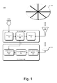
- Fig. 1 is a schematic illustration of a system for active waveform modulation for rotorcraft, according to embodiments.
- a system 100 comprises a radiofrequency (RF) transmitter 110, a controller 150 communicatively coupled to the transmitter 110, an antenna 126 for transceiving RF signals and a laser transceiver 140 for transceiving laser signals.
- RF radiofrequency
- an RF receiver may be associated with the RF transmitter 110 to establish an RF communication system.
- Transmitter 110 comprises an encoder 120, an RF modulator 122, and an amplifier 124.
- Antenna 126 is coupled to transmitter 110.
- data signals may be input to the encoder, which encodes the data signals using any conventional encoding scheme.
- the encoded signals may be passed to the RF modulator 122, which modulates the signals, and to amplifier 124, which amplifies the signals.
- the amplified signals may then be output to antenna 126 for transmission.
- Laser transceiver 140 may be include a laser diode or other suitable source to generate a targeted laser output and a receiver to receive laser signals reflected from a rotor 160.
- the laser source may be adapted to transmit pulsed laser signals in a frequency range between 1.5 micrometers ( ⁇ m) and 7 ⁇ m in the same direction in which the RF signals are transmitted.
- Laser transceiver 140 may include a photodiode or other suitable detector for detecting reflected laser signals.
- detection devices may be used, e.g., RADAR, a visual sensor, a radio frequency identifier (RFID) device or the like.
- Controller 150 implements a data collection module 152 to collect data relating to the reflected laser signals collected by laser transceiver 140 and an analysis module 154 to analyze the collected signals to produce an interference model 156.
- controller 150 may be implemented as a computer-based processing device comprising one or more integrated circuits which implement logic operations.
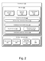
- Fig. 2 is a schematic illustration of a controller 150 in which portions of a system for active waveform modulation for rotorcraft may be implemented according to embodiments.
- controller 150 may include system hardware 220 and memory 230.
- System hardware 220 may include one or more processors 222, file store(s) 224, network interfaces 226, and an input/output (I/O) interface 228.
- processors means any type of computational element, such as but not limited to, a microprocessor, a microcontroller, a complex instruction set computing (CISC) microprocessor, a reduced instruction set (RISC) microprocessor, a very long instruction word (VLIW) microprocessor, or any other type of processor or processing circuit.
- CISC complex instruction set computing
- RISC reduced instruction set
- VLIW very long instruction word
- File store(s) 224 may be internal to controller 150 such as, e.g., one or more hard drives, solid state memory, CD-ROM drives, DVD-ROM drives, or other types of storage devices. File store 224 may also be external to controller 150 such as, e.g., one or more external hard drives, network attached storage, or a separate storage network.
- Network interface 226 may be implemented as a wired interface such as an Ethernet interface (see, e.g., Institute of Electrical and Electronics Engineers/IEEE 802.3-2002) or a wireless interface such as an IEEE 802.11a, b or g-compliant interface (see, e.g., IEEE Standard for IT-Telecommunications and information exchange between systems LAN/MAN--Part II: Wireless LAN Medium Access Control (MAC) and Physical Layer (PHY) specifications Amendment 4: Further Higher Data Rate Extension in the 2.4 GHz Band, 802.11G-2003).
- GPRS general packet radio service
- input/output devices 228 may including a display having a screen, one or more speakers, a keyboard, a mouse, a touch screen, a voice-activated input device, a track ball, and any other device that allows the controller 150 to receive input from a user.
- Memory 230 may be implemented as random access memory and/or read-only memory and may include an operating system 240 for managing operations of controller 150.
- operating system 240 includes a hardware interface module 254 that provides an interface to system hardware 220.
- operating system 240 may include a file system 250 that manages files used in the operation of controller 150 and a process control subsystem 252 that manages processes executing on controller 150.
- Operating system 240 may include (or manage) one or more communication interfaces that may operate in conjunction with system hardware 220 to transceive data packets and/or data streams from a remote source. Operating system 240 may further include a system call interface module 242 that provides an interface between the operating system 240 and one or more application modules resident in memory 230. Operating system 240 may be embodied as a UNIX operating system or any derivative thereof (e.g., Linux, Solaris, etc. ) or as a Windows® brand operating system, real-time OS (RTOS), or other operating systems.
- UNIX operating system or any derivative thereof (e.g., Linux, Solaris, etc. ) or as a Windows® brand operating system, real-time OS (RTOS), or other operating systems.
- RTOS real-time OS
- memory 230 includes one or more logic modules embodied as logic instructions encoded on a tangible, non-transitory memory to impart functionality to the controller 150.
- the embodiment depicted in Fig. 2 comprises a data collection module 152 and an analysis module 154, which generates an interference model 156. Additional details about the processes and operations implemented by these modules are described with reference to Fig. 3 below.
- the controller 150 cooperates with the transmitter 110 to implement active waveform modulation in a rotorcraft.
- an RF transmitter 110 and controller 150 may be positioned within a rotorcraft.
- Antenna 126 and laser transceiver 140 may be positioned within the rotorcraft or outside the rotorcraft.
- laser transceiver 140 directs a pulsed laser signal towards the rotor(s) 160 and receives laser signals reflected from the rotor(s) 160 and converts the reflected signals to appropriate data signals.
- a data collection module 152 collects the data signals.
- the analysis module 154 processes the data signals to generate an interference model 156. Data from the interference model may be provided to the RF modulator 122, which uses the data to modulate an RF transmission signal.
- a method for active waveform modulation includes at operation 310, transmitting RF signals from transmitter 110 and contemporaneously transmitting laser signals from laser transceiver 140.
- the laser transceiver transmits a laser signal pulsed at a frequency sufficiently high to resolve rotation of the rotors 160.
- the laser transceiver 140 receives reflections of the laser signal reflected from the rotors. The reflections are converted to appropriate electrical signals which are collected by the data collection module 152.
- analysis module 154 applies a range gating function to the signals to determine a measure of interference generated by the rotor 160.
- the measure of interference may be stored in a memory 230 at operation 325 as an interference model.
- the interference model may comprise a time series of interference data collected from reflected laser signals 380.
- the interference measure may be used to shutter and/or to modulate RF signals transmitted from transmitter 110. If at operation 330, if the interference measure exceeds a predetermined threshold, then control passes to operation 335 and one or more transmission parameters of the RF signal transmitted by transmitter are modified.
- a data transmission rate of the RF signals transmitted from transmitter 110 may be decreased when the interference measure exceeds a threshold. In other embodiments a transmission power may be increased when the interference measure exceeds a threshold.
- a data transmission rate of the RF signals transmitted from transmitter 110 may be increased when the interference measure falls below a threshold. In other embodiments a transmission power may be decreased when the interference measure falls below a threshold.
- the operations 310-345 may be repeated in a loop to define a method for active waveform modulation in transmitter 110.
- the method may be implemented by the system 100 depicted in Fig. 1 .
- the system 100 may be implemented on an aircraft such as a helicopter 400 depicted in Fig. 4 or an airplane 500 depicted in Fig. 5 .
- logic instructions as referred to herein relates to expressions which may be understood by one or more machines for performing one or more logical operations.
- logic instructions may comprise instructions which are interpretable by a processor compiler for executing one or more operations on one or more data objects.
- this is merely an example of machine-readable instructions and embodiments are not limited in this respect.
- a computer readable medium may comprise one or more storage devices for storing computer readable instructions or data.
- Such storage devices may comprise storage media such as, for example, optical, magnetic or semiconductor storage media.
- this is merely an example of a computer readable medium and embodiments are not limited in this respect.
- logic as referred to herein relates to structure for performing one or more logical operations.
- logic may comprise circuitry which provides one or more output signals based upon one or more input signals.
- Such circuitry may comprise a finite state machine which receives a digital input and provides a digital output, or circuitry which provides one or more analog output signals in response to one or more analog input signals.
- Such circuitry may be provided in an application specific integrated circuit (ASIC) or field programmable gate array (FPGA).
- ASIC application specific integrated circuit
- FPGA field programmable gate array
- logic may comprise machine-readable instructions stored in a memory in combination with processing circuitry to execute such machine-readable instructions.
- ASIC application specific integrated circuit
- FPGA field programmable gate array
- Some of the methods described herein may be embodied as logic instructions on a computer-readable medium. When executed on a processor, the logic instructions cause a processor to be programmed as a special-purpose machine that implements the described methods.
- the processor when configured by the logic instructions to execute the methods described herein, constitutes structure for performing the described methods.
- the methods described herein may be reduced to logic on, e.g., a field programmable gate array (FPGA), an application specific integrated circuit (ASIC) or the like.
- FPGA field programmable gate array
- ASIC application specific integrated circuit
- Coupled may mean that two or more elements are in direct physical or electrical contact.
- coupled may also mean that two or more elements may not be in direct contact with each other, but yet may still cooperate or interact with each other.
Landscapes
- Engineering & Computer Science (AREA)
- Computer Networks & Wireless Communication (AREA)
- Signal Processing (AREA)
- Radar Systems Or Details Thereof (AREA)
- Optical Radar Systems And Details Thereof (AREA)
Abstract
Description
- This invention relates to electronic communication via radiofrequency (RF) signals, and more particularly to systems and methods for active waveform shuttering in rotorcraft.
- Various vehicles rely on rotors to provide propulsion and/or lift. Common examples include helicopters, quadrotors, and propeller-driven aircraft. Other examples include fan boats, also referred to as air boats. Such vehicle may be referred to generally as rotorcraft.
- Some rotorcraft may include RF communication systems. For example, most aircraft include both voice communication systems and data communication systems which rely on RF communication links to communication with one or more ground-based communication systems with other aircraft, or satellites. In some circumstances rotation of the rotors may introduce interference with RF signals transmitted from a rotorcraft. Such interference may vary as a function various parameters including the rotor speed, the aircraft orientation, transmission direction and the signal frequency. Accordingly, systems and methods to mitigate such interference may find utility.
- In one embodiment there is provided a method comprising determining a measure of interference resulting from a rotorblade, providing the measure of interference to a radiofrequency (RF) modulator, and shuttering and/or modulating an RF transmission signal from the RF transmitter in response to the measure of interference.
- In another embodiment there is provided a communication system comprising a radiofrequency (RF) transmitter, an antenna communicatively coupled to the RF transmitter to direct an RF signal in a first direction, a laser range finder mounted to the antenna to direct a pulsed laser signal toward a rotorblade, (for example in the first direction) and receive reflected laser signals from a rotorblade, and logic to determine a measure of interference resulting from a rotorblade, provide the measure of interference to a radiofrequency (RF) transmitter, and shutter and/or modulate an RF transmission signal from the RF transmitter in response to the measure of interference.
- In another embodiment there is provided an aircraft comprising a communication system comprising a radiofrequency (RF) transmitter, an antenna communicatively coupled to the RF transmitter to direct an RF signal in a first direction, a laser ranger mounted to the antenna to direct a pulsed laser signal toward a rotorblade, (for example in the first direction) and receive reflected laser signals from a rotorblade, and logic to determine a measure of interference resulting from a rotorblade, provide the measure of interference to a radiofrequency (RF) transmitter, and shutter and/or modulate an RF transmission signal from the RF transmitter in response to the measure of interference.
- The features, functions and advantages discussed herein can be achieved independently in various embodiments described herein or may be combined in yet other embodiments, further details of which can be seen with reference to the following description and drawings.
- The detailed description is described with reference to the accompanying figures.
-
Fig. 1 is a schematic illustration of a system for active waveform modulation for rotorcraft, according to embodiments. -
Fig. 2 is a schematic illustration of a controller in which portions of a system for active waveform modulation for rotorcraft may be implemented according to embodiments. -
Fig. 3 is a flowchart illustrating operations in a method for active waveform modulation for rotorcraft, according to embodiments. -
Figs. 4 and 5 are schematic illustrations of aircraft in which a system for active waveform modulation for rotorcraft may be implemented according to embodiments. - Described herein are exemplary systems and methods for active waveform modulation in rotorcraft. Embodiments described here provide systems, methods, and logic for determining a measure of interference resulting from a rotorblade, providing the measure of interference to a radiofrequency (RF) modulator, and shuttering and/or modulating an RF transmission signal from the RF transmitter in response to the measure of interference. As used herein the term "shuttering" refers to cycling a signal on and off. In some embodiments an RF modulator may be used to shutter an RF signal. In alternate embodiments a transmitter may be cycled between a power on state and a power off state, or between a transmitting state and a non-transmitting state.
- In the following description, numerous specific details are set forth to provide a thorough understanding of various embodiments. However, it will be understood by those skilled in the art that the various embodiments may be practiced without the specific details. In other instances, well-known methods, procedures, components, and circuits have not been illustrated or described in detail so as not to obscure the particular embodiments.
-
Fig. 1 is a schematic illustration of a system for active waveform modulation for rotorcraft, according to embodiments. Referring toFig. 1 , in one embodiment asystem 100 comprises a radiofrequency (RF)transmitter 110, acontroller 150 communicatively coupled to thetransmitter 110, anantenna 126 for transceiving RF signals and alaser transceiver 140 for transceiving laser signals. One skilled in the art will recognize that an RF receiver may be associated with theRF transmitter 110 to establish an RF communication system. -
Transmitter 110 comprises anencoder 120, anRF modulator 122, and anamplifier 124.Antenna 126 is coupled totransmitter 110. In operation, data signals may be input to the encoder, which encodes the data signals using any conventional encoding scheme. The encoded signals may be passed to theRF modulator 122, which modulates the signals, and to amplifier 124, which amplifies the signals. The amplified signals may then be output toantenna 126 for transmission. -
Laser transceiver 140 may be include a laser diode or other suitable source to generate a targeted laser output and a receiver to receive laser signals reflected from arotor 160. In some embodiments the laser source may be adapted to transmit pulsed laser signals in a frequency range between 1.5 micrometers (µm) and 7 µm in the same direction in which the RF signals are transmitted.Laser transceiver 140 may include a photodiode or other suitable detector for detecting reflected laser signals. One skilled in the art will recognize that other detection devices may be used, e.g., RADAR, a visual sensor, a radio frequency identifier (RFID) device or the like. -
Controller 150 implements adata collection module 152 to collect data relating to the reflected laser signals collected bylaser transceiver 140 and ananalysis module 154 to analyze the collected signals to produce aninterference model 156. In someembodiments controller 150 may be implemented as a computer-based processing device comprising one or more integrated circuits which implement logic operations.Fig. 2 is a schematic illustration of acontroller 150 in which portions of a system for active waveform modulation for rotorcraft may be implemented according to embodiments. - Referring to
Fig. 2 , in one embodiment,controller 150 may includesystem hardware 220 andmemory 230.System hardware 220 may include one ormore processors 222, file store(s) 224,network interfaces 226, and an input/output (I/O)interface 228. As used herein, the term "processor" means any type of computational element, such as but not limited to, a microprocessor, a microcontroller, a complex instruction set computing (CISC) microprocessor, a reduced instruction set (RISC) microprocessor, a very long instruction word (VLIW) microprocessor, or any other type of processor or processing circuit. - File store(s) 224 may be internal to controller 150 such as, e.g., one or more hard drives, solid state memory, CD-ROM drives, DVD-ROM drives, or other types of storage devices.
File store 224 may also be external to controller 150 such as, e.g., one or more external hard drives, network attached storage, or a separate storage network. -
Network interface 226 may be implemented as a wired interface such as an Ethernet interface (see, e.g., Institute of Electrical and Electronics Engineers/IEEE 802.3-2002) or a wireless interface such as an IEEE 802.11a, b or g-compliant interface (see, e.g., IEEE Standard for IT-Telecommunications and information exchange between systems LAN/MAN--Part II: Wireless LAN Medium Access Control (MAC) and Physical Layer (PHY) specifications Amendment 4: Further Higher Data Rate Extension in the 2.4 GHz Band, 802.11G-2003). Another example of a wireless interface would be a general packet radio service (GPRS) interface (see, e.g., Guidelines on GPRS Handset Requirements, Global System for Mobile Communications/GSM Association, Ver. 3.0.1, December 2002). - In one embodiment, input/
output devices 228 may including a display having a screen, one or more speakers, a keyboard, a mouse, a touch screen, a voice-activated input device, a track ball, and any other device that allows thecontroller 150 to receive input from a user. -
Memory 230 may be implemented as random access memory and/or read-only memory and may include anoperating system 240 for managing operations ofcontroller 150. In one embodiment,operating system 240 includes ahardware interface module 254 that provides an interface tosystem hardware 220. In addition,operating system 240 may include afile system 250 that manages files used in the operation ofcontroller 150 and aprocess control subsystem 252 that manages processes executing oncontroller 150. -
Operating system 240 may include (or manage) one or more communication interfaces that may operate in conjunction withsystem hardware 220 to transceive data packets and/or data streams from a remote source.Operating system 240 may further include a systemcall interface module 242 that provides an interface between theoperating system 240 and one or more application modules resident inmemory 230.Operating system 240 may be embodied as a UNIX operating system or any derivative thereof (e.g., Linux, Solaris, etc.) or as a Windows® brand operating system, real-time OS (RTOS), or other operating systems. - In one embodiment,
memory 230 includes one or more logic modules embodied as logic instructions encoded on a tangible, non-transitory memory to impart functionality to thecontroller 150. The embodiment depicted inFig. 2 comprises adata collection module 152 and ananalysis module 154, which generates aninterference model 156. Additional details about the processes and operations implemented by these modules are described with reference toFig. 3 below. - In operation, the
controller 150 cooperates with thetransmitter 110 to implement active waveform modulation in a rotorcraft. In a brief overview, in embodiments described herein, anRF transmitter 110 andcontroller 150 may be positioned within a rotorcraft.Antenna 126 andlaser transceiver 140 may be positioned within the rotorcraft or outside the rotorcraft. Inoperation laser transceiver 140 directs a pulsed laser signal towards the rotor(s) 160 and receives laser signals reflected from the rotor(s) 160 and converts the reflected signals to appropriate data signals. Adata collection module 152 collects the data signals. Theanalysis module 154 processes the data signals to generate aninterference model 156. Data from the interference model may be provided to theRF modulator 122, which uses the data to modulate an RF transmission signal. - In greater detail, and referring to
Fig. 3 , in some embodiments a method for active waveform modulation includes atoperation 310, transmitting RF signals fromtransmitter 110 and contemporaneously transmitting laser signals fromlaser transceiver 140. In some embodiments the laser transceiver transmits a laser signal pulsed at a frequency sufficiently high to resolve rotation of therotors 160. Atoperation 315 thelaser transceiver 140 receives reflections of the laser signal reflected from the rotors. The reflections are converted to appropriate electrical signals which are collected by thedata collection module 152. Atoperation 320analysis module 154 applies a range gating function to the signals to determine a measure of interference generated by therotor 160. In some embodiments the measure of interference may be stored in amemory 230 atoperation 325 as an interference model. By way of example, in some embodiments the interference model may comprise a time series of interference data collected from reflected laser signals 380. - In some embodiments the interference measure may be used to shutter and/or to modulate RF signals transmitted from
transmitter 110. If atoperation 330, if the interference measure exceeds a predetermined threshold, then control passes tooperation 335 and one or more transmission parameters of the RF signal transmitted by transmitter are modified. By way of example, in some embodiments a data transmission rate of the RF signals transmitted fromtransmitter 110 may be decreased when the interference measure exceeds a threshold. In other embodiments a transmission power may be increased when the interference measure exceeds a threshold. - By contrast, if at
operation 330 the interference measure does not exceed a threshold, then control passes tooperation 340. If atoperation 340 the interference measure falls below a predetermined threshold, then control passes tooperation 345 and one or more transmission parameters of the RF signal transmitted by transmitter are modified. By way of example, in some embodiments a data transmission rate of the RF signals transmitted fromtransmitter 110 may be increased when the interference measure falls below a threshold. In other embodiments a transmission power may be decreased when the interference measure falls below a threshold. - Thus, the operations 310-345 may be repeated in a loop to define a method for active waveform modulation in
transmitter 110. The method may be implemented by thesystem 100 depicted inFig. 1 . In some embodiments thesystem 100 may be implemented on an aircraft such as ahelicopter 400 depicted inFig. 4 or anairplane 500 depicted inFig. 5 . - The terms "logic instructions" as referred to herein relates to expressions which may be understood by one or more machines for performing one or more logical operations. For example, logic instructions may comprise instructions which are interpretable by a processor compiler for executing one or more operations on one or more data objects. However, this is merely an example of machine-readable instructions and embodiments are not limited in this respect.
- The terms "computer readable medium" as referred to herein relates to media capable of maintaining expressions which are perceivable by one or more machines. For example, a computer readable medium may comprise one or more storage devices for storing computer readable instructions or data. Such storage devices may comprise storage media such as, for example, optical, magnetic or semiconductor storage media. However, this is merely an example of a computer readable medium and embodiments are not limited in this respect.
- The term "logic" as referred to herein relates to structure for performing one or more logical operations. For example, logic may comprise circuitry which provides one or more output signals based upon one or more input signals. Such circuitry may comprise a finite state machine which receives a digital input and provides a digital output, or circuitry which provides one or more analog output signals in response to one or more analog input signals. Such circuitry may be provided in an application specific integrated circuit (ASIC) or field programmable gate array (FPGA). Also, logic may comprise machine-readable instructions stored in a memory in combination with processing circuitry to execute such machine-readable instructions. However, these are merely examples of structures which may provide logic and embodiments are not limited in this respect.
- Some of the methods described herein may be embodied as logic instructions on a computer-readable medium. When executed on a processor, the logic instructions cause a processor to be programmed as a special-purpose machine that implements the described methods. The processor, when configured by the logic instructions to execute the methods described herein, constitutes structure for performing the described methods. Alternatively, the methods described herein may be reduced to logic on, e.g., a field programmable gate array (FPGA), an application specific integrated circuit (ASIC) or the like.
- In the description and claims, the terms coupled and connected, along with their derivatives, may be used. In particular embodiments, connected may be used to indicate that two or more elements are in direct physical or electrical contact with each other. Coupled may mean that two or more elements are in direct physical or electrical contact. However, coupled may also mean that two or more elements may not be in direct contact with each other, but yet may still cooperate or interact with each other.
- Reference in the specification to "one embodiment" or "some embodiments" means that a particular feature, structure, or characteristic described in connection with the embodiment is included in at least an implementation. The appearances of the phrase "in one embodiment" in various places in the specification may or may not be all referring to the same embodiment.
- Further, the disclosure comprises embodiments according to the following clauses:
- Clause 1. An aircraft comprising:
- a system, comprising:
- a radiofrequency (RF) transmitter;
- an antenna communicatively coupled to the RF transmitter to direct an RF signal in a first direction;
- a laser ranger mounted to the antenna to:
- direct a pulsed laser signal in the first direction; and
- receive reflected laser signals from a rotorblade;
- logic to:
- determine a measure of interference resulting from a rotorblade;
- provide the measure of interference to a radiofrequency (RF) transmitter; and
- use the measure of interference to shutter an RF transmission signal for the RF transmitter.
- a system, comprising:
- Clause 2. The aircraft of Clause 1, further comprising logic to evaluate reflected laser signals from the rotorblade to determine a measure of interference.
- Clause 3. The aircraft of Clause 2, further comprising logic to apply a range gating function to the reflected laser signals.
- Clause 4. The aircraft of Clause 3, further comprising logic to:
- construct an interference model from the reflected laser signals from the rotorblade; and
- store the interference model in a non-transitory, computer readable memory.
- Clause 5. The aircraft of Clause 1, further comprising logic to increase a transmission rate in response to the measure of interference falling below a threshold.
- Clause 6. The aircraft of Clause 1, further comprising logic to decrease a transmission rate in response to the measure of interference rising above a threshold.
- Although embodiments have been described in language specific to structural features and/or methodological acts, it is to be understood that claimed subject matter may not be limited to the specific features or acts described. Rather, the specific features and acts are disclosed as sample forms of implementing the claimed subject matter.
Claims (15)
- A method, comprising:determining a measure of interference resulting from a rotorblade (160);providing the measure of interference to a radiofrequency (RF) modulator (122); andusing the measure of interference to shutter and/or modulate an RF transmission signal for an RF transmitter (110).
- The method of claim 1, wherein determining a measure of interference resulting from a rotorblade (160) comprises:directing a pulsed laser signal toward the rotorblade (160); andevaluating reflected laser signals from the rotorblade (160) to determine a measure of interference.
- The method of claim 2, wherein directing a pulsed laser signal toward the rotorblade (160) comprises transmitting the pulsed laser signal and an RF signal contemporaneously.
- The method of claim 2, wherein evaluating reflected laser signals from the rotorblade comprises applying a range gating function to the reflected laser signals.
- The method of claim 4, further comprising:constructing an interference model (156) from the reflected laser signals from the rotorblade (160); andstoring the interference model (156) in a non-transitory, computer readable memory (230).
- The method of claim 1, wherein using the measure of interference to shutter and/or modulate an RF transmission signal for an RF transmitter (110) comprises increasing a transmission rate in response to the measure of interference falling below a threshold.
- The method of claim 1, wherein using the measure of interference to shutter and/or modulate an RF transmission signal for an RF transmitter (110) comprises decreasing a transmission rate in response to the measure of interference rising above a threshold.
- A system, comprising:a radiofrequency (RF) transmitter (110);an antenna (126) communicatively coupled to the RF transmitter (110) to direct an RF signal in a first direction;a laser ranger mounted to the antenna to:direct a pulsed laser signal towards a rotorblade (160); andreceive reflected laser signals from a rotorblade (160);logic to:determine a measure of interference resulting from the rotorblade (160);provide the measure of interference to the radiofrequency (RF) transmitter (110); anduse the measure of interference to shutter and/or modulate an RF transmission signal for the RF transmitter (110).
- The system of claim 8, further comprising logic to evaluate reflected laser signals from the rotorblade (160) to determine a measure of interference.
- The system of claim 9, further comprising logic to apply a range gating function to the reflected laser signals.
- The system of claim 10, further comprising logic to:construct an interference model (156) from the reflected laser signals from the rotorblade (160); andstore the interference model (156) in a non-transitory, computer readable memory (230).
- The system of claim 8, further comprising logic to increase a transmission rate in response to the measure of interference falling below a threshold.
- The system of claim 8, further comprising logic to decrease a transmission rate in response to the measure of interference rising above a threshold.
- The system of any of claims 8 to 13, wherein the pulsed laser signal directed towards the rotorblade is directed in the first direction.
- An aircraft (400, 500) comprising the system of any of claims 8 to 14.
Applications Claiming Priority (1)
| Application Number | Priority Date | Filing Date | Title |
|---|---|---|---|
| US13/744,124 US9319077B2 (en) | 2013-01-17 | 2013-01-17 | Active waveform shuttering for rotorcraft |
Publications (3)
| Publication Number | Publication Date |
|---|---|
| EP2757696A1 true EP2757696A1 (en) | 2014-07-23 |
| EP2757696B1 EP2757696B1 (en) | 2023-03-15 |
| EP2757696B8 EP2757696B8 (en) | 2023-04-19 |
Family
ID=50033331
Family Applications (1)
| Application Number | Title | Priority Date | Filing Date |
|---|---|---|---|
| EP14151650.0A Active EP2757696B8 (en) | 2013-01-17 | 2014-01-17 | Waveform modulation for rotorcraft. |
Country Status (3)
| Country | Link |
|---|---|
| US (1) | US9319077B2 (en) |
| EP (1) | EP2757696B8 (en) |
| AU (1) | AU2014200018B2 (en) |
Families Citing this family (4)
| Publication number | Priority date | Publication date | Assignee | Title |
|---|---|---|---|---|
| US20140219401A1 (en) * | 2013-02-04 | 2014-08-07 | Koby Finkelstein | Rfi mitigation via duty cycle control |
| US20150055564A1 (en) * | 2013-08-20 | 2015-02-26 | GM Global Technology Operations LLC | Methods and apparatus for configuration of a vehicle-based wireless signal transmission range |
| US20150063148A1 (en) * | 2013-09-04 | 2015-03-05 | Qualcomm Incorporated | Robust inter-radio access technology operations in unlicensed spectrum |
| US12041449B2 (en) * | 2020-04-10 | 2024-07-16 | Qualcomm Incorporated | Method and apparatus for verifying mobile device communications |
Citations (1)
| Publication number | Priority date | Publication date | Assignee | Title |
|---|---|---|---|---|
| US5606734A (en) * | 1993-03-02 | 1997-02-25 | American Nucleonics Corporation | Structure generated composite reference signal for interference suppression in an adaptive loop |
Family Cites Families (10)
| Publication number | Priority date | Publication date | Assignee | Title |
|---|---|---|---|---|
| BRPI9906339B1 (en) * | 1998-04-17 | 2016-09-20 | Matsushita Electric Industrial Co Ltd | baud rate control apparatus, base station apparatus and baud rate control method |
| US6448924B1 (en) | 1999-10-12 | 2002-09-10 | Smiths Aerospace, Inc. | Microwave blade tracker |
| US7257094B2 (en) * | 2001-01-16 | 2007-08-14 | Texas Instruments Incorporated | Jointly controlling transmission rate and power in a communications system |
| US7084739B2 (en) * | 2002-06-28 | 2006-08-01 | Brother Kogyo Kabushiki Kaisha | Communication system, and interrogator and transponder for the system |
| US6781677B1 (en) * | 2003-01-31 | 2004-08-24 | The Boeing Company | Laser range finding apparatus |
| US7044044B2 (en) * | 2003-10-17 | 2006-05-16 | Computer Science Corporation | Radio frequency triggered directed energy munition |
| US20070257194A1 (en) * | 2005-03-22 | 2007-11-08 | Mueller Eric R | Terahertz heterodyne tomographic imaging system |
| US7548166B2 (en) * | 2005-05-13 | 2009-06-16 | Ems Technologies, Inc. | Tine-mounted antenna for an RFID |
| US7665663B2 (en) * | 2006-07-07 | 2010-02-23 | Itt Manufacturing Enterprises, Inc. | Method and apparatus for target discrimination within return signals |
| US8019284B2 (en) * | 2008-12-05 | 2011-09-13 | The Boeing Company | Helicopter rotor blade blockage blanking |
-
2013
- 2013-01-17 US US13/744,124 patent/US9319077B2/en active Active
-
2014
- 2014-01-03 AU AU2014200018A patent/AU2014200018B2/en active Active
- 2014-01-17 EP EP14151650.0A patent/EP2757696B8/en active Active
Patent Citations (1)
| Publication number | Priority date | Publication date | Assignee | Title |
|---|---|---|---|---|
| US5606734A (en) * | 1993-03-02 | 1997-02-25 | American Nucleonics Corporation | Structure generated composite reference signal for interference suppression in an adaptive loop |
Non-Patent Citations (1)
| Title |
|---|
| "Guidelines on GPRS Handset Requirements", December 2002, GLOBAL SYSTEM FOR MOBILE COMMUNICATIONS/GSM ASSOCIATION |
Also Published As
| Publication number | Publication date |
|---|---|
| US9319077B2 (en) | 2016-04-19 |
| AU2014200018A1 (en) | 2014-07-31 |
| AU2014200018B2 (en) | 2017-02-02 |
| US20140199953A1 (en) | 2014-07-17 |
| EP2757696B1 (en) | 2023-03-15 |
| EP2757696B8 (en) | 2023-04-19 |
Similar Documents
| Publication | Publication Date | Title |
|---|---|---|
| Nguyen et al. | Matthan: Drone presence detection by identifying physical signatures in the drone's RF communication | |
| US10629067B1 (en) | Selective prevention of signal transmission by device during aircraft takeoff and/or landing | |
| CN103869822B (en) | The perception of many rotor wing unmanned aerial vehicles and avoidance system and bypassing method thereof | |
| CN205403847U (en) | A early warning device for unmanned aerial vehicle | |
| AU2014200018B2 (en) | Active waveform shuttering for rotocraft | |
| CN107992029A (en) | Unmanned plane device for detecting performance based on status monitoring | |
| CN103630890B (en) | A kind of adaptive microwave speed measuring device and method thereof | |
| CN105353390A (en) | Navigation system enabling unmanned aerial vehicle to avoid wireless interference and method | |
| KR101949796B1 (en) | Method for controlling drone of using speech recognition, apparatus and system for executing the same | |
| CN111615109A (en) | A 5G network-connected drone identification and authentication method | |
| WO2018094747A1 (en) | Control method, remote control and drone | |
| CN116699593A (en) | A communication and positioning method and system for an unmanned aerial vehicle | |
| KR102453333B1 (en) | Drone performance test system using gps signals | |
| Nakata et al. | RF techniques for motion compensation of an Unmanned Aerial Vehicle for remote radar life sensing | |
| CN106873618A (en) | A kind of monitoring unmanned system | |
| US20200371218A1 (en) | Signal processing device and signal processing method | |
| CN203350445U (en) | On-board anti-collision system testing device | |
| US10591590B1 (en) | Control algorithm for wireless sensor to estimate and calculate environmental parameters | |
| CN106950983B (en) | Obstacle avoidance method and device for unmanned aerial vehicle | |
| CN111077898A (en) | Unmanned aerial vehicle fixed point landing ground guidance system | |
| CN204473132U (en) | A kind of unmanned gyroplane with wireless network bridging functionality | |
| US20200174434A1 (en) | Cloud-based light unit health monitoring system | |
| CN210639466U (en) | UAV flight control device based on Tiantong-1 | |
| RU2571870C1 (en) | Atmospheric sounding radar system | |
| CN205539455U (en) | A device that is used for range finding of mobile device and follows location |
Legal Events
| Date | Code | Title | Description |
|---|---|---|---|
| PUAI | Public reference made under article 153(3) epc to a published international application that has entered the european phase |
Free format text: ORIGINAL CODE: 0009012 |
|
| 17P | Request for examination filed |
Effective date: 20140117 |
|
| AK | Designated contracting states |
Kind code of ref document: A1 Designated state(s): AL AT BE BG CH CY CZ DE DK EE ES FI FR GB GR HR HU IE IS IT LI LT LU LV MC MK MT NL NO PL PT RO RS SE SI SK SM TR |
|
| AX | Request for extension of the european patent |
Extension state: BA ME |
|
| R17P | Request for examination filed (corrected) |
Effective date: 20140801 |
|
| RBV | Designated contracting states (corrected) |
Designated state(s): AL AT BE BG CH CY CZ DE DK EE ES FI FR GB GR HR HU IE IS IT LI LT LU LV MC MK MT NL NO PL PT RO RS SE SI SK SM TR |
|
| STAA | Information on the status of an ep patent application or granted ep patent |
Free format text: STATUS: EXAMINATION IS IN PROGRESS |
|
| 17Q | First examination report despatched |
Effective date: 20181120 |
|
| GRAP | Despatch of communication of intention to grant a patent |
Free format text: ORIGINAL CODE: EPIDOSNIGR1 |
|
| STAA | Information on the status of an ep patent application or granted ep patent |
Free format text: STATUS: GRANT OF PATENT IS INTENDED |
|
| INTG | Intention to grant announced |
Effective date: 20200227 |
|
| GRAJ | Information related to disapproval of communication of intention to grant by the applicant or resumption of examination proceedings by the epo deleted |
Free format text: ORIGINAL CODE: EPIDOSDIGR1 |
|
| STAA | Information on the status of an ep patent application or granted ep patent |
Free format text: STATUS: EXAMINATION IS IN PROGRESS |
|
| INTC | Intention to grant announced (deleted) | ||
| GRAP | Despatch of communication of intention to grant a patent |
Free format text: ORIGINAL CODE: EPIDOSNIGR1 |
|
| STAA | Information on the status of an ep patent application or granted ep patent |
Free format text: STATUS: GRANT OF PATENT IS INTENDED |
|
| INTG | Intention to grant announced |
Effective date: 20221010 |
|
| GRAS | Grant fee paid |
Free format text: ORIGINAL CODE: EPIDOSNIGR3 |
|
| GRAA | (expected) grant |
Free format text: ORIGINAL CODE: 0009210 |
|
| STAA | Information on the status of an ep patent application or granted ep patent |
Free format text: STATUS: THE PATENT HAS BEEN GRANTED |
|
| REG | Reference to a national code |
Ref country code: DE Ref legal event code: R081 Ref document number: 602014086460 Country of ref document: DE Owner name: THE BOEING COMPANY, ARLINGTON, US Free format text: FORMER OWNER: THE BOEING COMPANY, CHICAGO, IL, US |
|
| AK | Designated contracting states |
Kind code of ref document: B1 Designated state(s): AL AT BE BG CH CY CZ DE DK EE ES FI FR GB GR HR HU IE IS IT LI LT LU LV MC MK MT NL NO PL PT RO RS SE SI SK SM TR |
|
| REG | Reference to a national code |
Ref country code: CH Ref legal event code: EP Ref country code: GB Ref legal event code: FG4D |
|
| RAP4 | Party data changed (patent owner data changed or rights of a patent transferred) |
Owner name: THE BOEING COMPANY |
|
| REG | Reference to a national code |
Ref country code: CH Ref legal event code: PK Free format text: BERICHTIGUNG B8 |
|
| REG | Reference to a national code |
Ref country code: DE Ref legal event code: R096 Ref document number: 602014086460 Country of ref document: DE |
|
| REG | Reference to a national code |
Ref country code: IE Ref legal event code: FG4D |
|
| REG | Reference to a national code |
Ref country code: AT Ref legal event code: REF Ref document number: 1554576 Country of ref document: AT Kind code of ref document: T Effective date: 20230415 |
|
| P01 | Opt-out of the competence of the unified patent court (upc) registered |
Effective date: 20230518 |
|
| REG | Reference to a national code |
Ref country code: LT Ref legal event code: MG9D |
|
| REG | Reference to a national code |
Ref country code: NL Ref legal event code: MP Effective date: 20230315 |
|
| PG25 | Lapsed in a contracting state [announced via postgrant information from national office to epo] |
Ref country code: RS Free format text: LAPSE BECAUSE OF FAILURE TO SUBMIT A TRANSLATION OF THE DESCRIPTION OR TO PAY THE FEE WITHIN THE PRESCRIBED TIME-LIMIT Effective date: 20230315 Ref country code: NO Free format text: LAPSE BECAUSE OF FAILURE TO SUBMIT A TRANSLATION OF THE DESCRIPTION OR TO PAY THE FEE WITHIN THE PRESCRIBED TIME-LIMIT Effective date: 20230615 Ref country code: LV Free format text: LAPSE BECAUSE OF FAILURE TO SUBMIT A TRANSLATION OF THE DESCRIPTION OR TO PAY THE FEE WITHIN THE PRESCRIBED TIME-LIMIT Effective date: 20230315 Ref country code: LT Free format text: LAPSE BECAUSE OF FAILURE TO SUBMIT A TRANSLATION OF THE DESCRIPTION OR TO PAY THE FEE WITHIN THE PRESCRIBED TIME-LIMIT Effective date: 20230315 Ref country code: HR Free format text: LAPSE BECAUSE OF FAILURE TO SUBMIT A TRANSLATION OF THE DESCRIPTION OR TO PAY THE FEE WITHIN THE PRESCRIBED TIME-LIMIT Effective date: 20230315 |
|
| REG | Reference to a national code |
Ref country code: AT Ref legal event code: MK05 Ref document number: 1554576 Country of ref document: AT Kind code of ref document: T Effective date: 20230315 |
|
| PG25 | Lapsed in a contracting state [announced via postgrant information from national office to epo] |
Ref country code: SE Free format text: LAPSE BECAUSE OF FAILURE TO SUBMIT A TRANSLATION OF THE DESCRIPTION OR TO PAY THE FEE WITHIN THE PRESCRIBED TIME-LIMIT Effective date: 20230315 Ref country code: NL Free format text: LAPSE BECAUSE OF FAILURE TO SUBMIT A TRANSLATION OF THE DESCRIPTION OR TO PAY THE FEE WITHIN THE PRESCRIBED TIME-LIMIT Effective date: 20230315 Ref country code: GR Free format text: LAPSE BECAUSE OF FAILURE TO SUBMIT A TRANSLATION OF THE DESCRIPTION OR TO PAY THE FEE WITHIN THE PRESCRIBED TIME-LIMIT Effective date: 20230616 Ref country code: FI Free format text: LAPSE BECAUSE OF FAILURE TO SUBMIT A TRANSLATION OF THE DESCRIPTION OR TO PAY THE FEE WITHIN THE PRESCRIBED TIME-LIMIT Effective date: 20230315 |
|
| PG25 | Lapsed in a contracting state [announced via postgrant information from national office to epo] |
Ref country code: SM Free format text: LAPSE BECAUSE OF FAILURE TO SUBMIT A TRANSLATION OF THE DESCRIPTION OR TO PAY THE FEE WITHIN THE PRESCRIBED TIME-LIMIT Effective date: 20230315 Ref country code: RO Free format text: LAPSE BECAUSE OF FAILURE TO SUBMIT A TRANSLATION OF THE DESCRIPTION OR TO PAY THE FEE WITHIN THE PRESCRIBED TIME-LIMIT Effective date: 20230315 Ref country code: PT Free format text: LAPSE BECAUSE OF FAILURE TO SUBMIT A TRANSLATION OF THE DESCRIPTION OR TO PAY THE FEE WITHIN THE PRESCRIBED TIME-LIMIT Effective date: 20230717 Ref country code: ES Free format text: LAPSE BECAUSE OF FAILURE TO SUBMIT A TRANSLATION OF THE DESCRIPTION OR TO PAY THE FEE WITHIN THE PRESCRIBED TIME-LIMIT Effective date: 20230315 Ref country code: EE Free format text: LAPSE BECAUSE OF FAILURE TO SUBMIT A TRANSLATION OF THE DESCRIPTION OR TO PAY THE FEE WITHIN THE PRESCRIBED TIME-LIMIT Effective date: 20230315 Ref country code: CZ Free format text: LAPSE BECAUSE OF FAILURE TO SUBMIT A TRANSLATION OF THE DESCRIPTION OR TO PAY THE FEE WITHIN THE PRESCRIBED TIME-LIMIT Effective date: 20230315 Ref country code: AT Free format text: LAPSE BECAUSE OF FAILURE TO SUBMIT A TRANSLATION OF THE DESCRIPTION OR TO PAY THE FEE WITHIN THE PRESCRIBED TIME-LIMIT Effective date: 20230315 |
|
| PG25 | Lapsed in a contracting state [announced via postgrant information from national office to epo] |
Ref country code: SK Free format text: LAPSE BECAUSE OF FAILURE TO SUBMIT A TRANSLATION OF THE DESCRIPTION OR TO PAY THE FEE WITHIN THE PRESCRIBED TIME-LIMIT Effective date: 20230315 Ref country code: PL Free format text: LAPSE BECAUSE OF FAILURE TO SUBMIT A TRANSLATION OF THE DESCRIPTION OR TO PAY THE FEE WITHIN THE PRESCRIBED TIME-LIMIT Effective date: 20230315 Ref country code: IS Free format text: LAPSE BECAUSE OF FAILURE TO SUBMIT A TRANSLATION OF THE DESCRIPTION OR TO PAY THE FEE WITHIN THE PRESCRIBED TIME-LIMIT Effective date: 20230715 |
|
| REG | Reference to a national code |
Ref country code: DE Ref legal event code: R097 Ref document number: 602014086460 Country of ref document: DE |
|
| PLBE | No opposition filed within time limit |
Free format text: ORIGINAL CODE: 0009261 |
|
| STAA | Information on the status of an ep patent application or granted ep patent |
Free format text: STATUS: NO OPPOSITION FILED WITHIN TIME LIMIT |
|
| PG25 | Lapsed in a contracting state [announced via postgrant information from national office to epo] |
Ref country code: SI Free format text: LAPSE BECAUSE OF FAILURE TO SUBMIT A TRANSLATION OF THE DESCRIPTION OR TO PAY THE FEE WITHIN THE PRESCRIBED TIME-LIMIT Effective date: 20230315 Ref country code: DK Free format text: LAPSE BECAUSE OF FAILURE TO SUBMIT A TRANSLATION OF THE DESCRIPTION OR TO PAY THE FEE WITHIN THE PRESCRIBED TIME-LIMIT Effective date: 20230315 |
|
| 26N | No opposition filed |
Effective date: 20231218 |
|
| PG25 | Lapsed in a contracting state [announced via postgrant information from national office to epo] |
Ref country code: IT Free format text: LAPSE BECAUSE OF FAILURE TO SUBMIT A TRANSLATION OF THE DESCRIPTION OR TO PAY THE FEE WITHIN THE PRESCRIBED TIME-LIMIT Effective date: 20230315 |
|
| PG25 | Lapsed in a contracting state [announced via postgrant information from national office to epo] |
Ref country code: MC Free format text: LAPSE BECAUSE OF FAILURE TO SUBMIT A TRANSLATION OF THE DESCRIPTION OR TO PAY THE FEE WITHIN THE PRESCRIBED TIME-LIMIT Effective date: 20230315 |
|
| PG25 | Lapsed in a contracting state [announced via postgrant information from national office to epo] |
Ref country code: MC Free format text: LAPSE BECAUSE OF FAILURE TO SUBMIT A TRANSLATION OF THE DESCRIPTION OR TO PAY THE FEE WITHIN THE PRESCRIBED TIME-LIMIT Effective date: 20230315 |
|
| REG | Reference to a national code |
Ref country code: CH Ref legal event code: PL |
|
| PG25 | Lapsed in a contracting state [announced via postgrant information from national office to epo] |
Ref country code: LU Free format text: LAPSE BECAUSE OF NON-PAYMENT OF DUE FEES Effective date: 20240117 |
|
| PG25 | Lapsed in a contracting state [announced via postgrant information from national office to epo] |
Ref country code: LU Free format text: LAPSE BECAUSE OF NON-PAYMENT OF DUE FEES Effective date: 20240117 |
|
| PG25 | Lapsed in a contracting state [announced via postgrant information from national office to epo] |
Ref country code: BE Free format text: LAPSE BECAUSE OF NON-PAYMENT OF DUE FEES Effective date: 20240131 |
|
| PG25 | Lapsed in a contracting state [announced via postgrant information from national office to epo] |
Ref country code: CH Free format text: LAPSE BECAUSE OF NON-PAYMENT OF DUE FEES Effective date: 20240131 |
|
| PG25 | Lapsed in a contracting state [announced via postgrant information from national office to epo] |
Ref country code: CH Free format text: LAPSE BECAUSE OF NON-PAYMENT OF DUE FEES Effective date: 20240131 Ref country code: BE Free format text: LAPSE BECAUSE OF NON-PAYMENT OF DUE FEES Effective date: 20240131 |
|
| REG | Reference to a national code |
Ref country code: BE Ref legal event code: MM Effective date: 20240131 |
|
| PG25 | Lapsed in a contracting state [announced via postgrant information from national office to epo] |
Ref country code: BG Free format text: LAPSE BECAUSE OF FAILURE TO SUBMIT A TRANSLATION OF THE DESCRIPTION OR TO PAY THE FEE WITHIN THE PRESCRIBED TIME-LIMIT Effective date: 20230315 |
|
| PG25 | Lapsed in a contracting state [announced via postgrant information from national office to epo] |
Ref country code: BG Free format text: LAPSE BECAUSE OF FAILURE TO SUBMIT A TRANSLATION OF THE DESCRIPTION OR TO PAY THE FEE WITHIN THE PRESCRIBED TIME-LIMIT Effective date: 20230315 |
|
| PG25 | Lapsed in a contracting state [announced via postgrant information from national office to epo] |
Ref country code: IE Free format text: LAPSE BECAUSE OF NON-PAYMENT OF DUE FEES Effective date: 20240117 |
|
| PG25 | Lapsed in a contracting state [announced via postgrant information from national office to epo] |
Ref country code: IE Free format text: LAPSE BECAUSE OF NON-PAYMENT OF DUE FEES Effective date: 20240117 |
|
| PG25 | Lapsed in a contracting state [announced via postgrant information from national office to epo] |
Ref country code: CY Free format text: LAPSE BECAUSE OF FAILURE TO SUBMIT A TRANSLATION OF THE DESCRIPTION OR TO PAY THE FEE WITHIN THE PRESCRIBED TIME-LIMIT; INVALID AB INITIO Effective date: 20140117 |
|
| PG25 | Lapsed in a contracting state [announced via postgrant information from national office to epo] |
Ref country code: HU Free format text: LAPSE BECAUSE OF FAILURE TO SUBMIT A TRANSLATION OF THE DESCRIPTION OR TO PAY THE FEE WITHIN THE PRESCRIBED TIME-LIMIT; INVALID AB INITIO Effective date: 20140117 |
|
| PG25 | Lapsed in a contracting state [announced via postgrant information from national office to epo] |
Ref country code: TR Free format text: LAPSE BECAUSE OF FAILURE TO SUBMIT A TRANSLATION OF THE DESCRIPTION OR TO PAY THE FEE WITHIN THE PRESCRIBED TIME-LIMIT Effective date: 20230315 |
|
| PGFP | Annual fee paid to national office [announced via postgrant information from national office to epo] |
Ref country code: GB Payment date: 20260127 Year of fee payment: 13 |
|
| PGFP | Annual fee paid to national office [announced via postgrant information from national office to epo] |
Ref country code: DE Payment date: 20260128 Year of fee payment: 13 |
|
| PGFP | Annual fee paid to national office [announced via postgrant information from national office to epo] |
Ref country code: FR Payment date: 20260126 Year of fee payment: 13 |