EP2757657A1 - Moving-vehicle electric power feeding system - Google Patents
Moving-vehicle electric power feeding system Download PDFInfo
- Publication number
- EP2757657A1 EP2757657A1 EP12831164.4A EP12831164A EP2757657A1 EP 2757657 A1 EP2757657 A1 EP 2757657A1 EP 12831164 A EP12831164 A EP 12831164A EP 2757657 A1 EP2757657 A1 EP 2757657A1
- Authority
- EP
- European Patent Office
- Prior art keywords
- power
- transmitting
- power supply
- vehicle
- electric power
- Prior art date
- Legal status (The legal status is an assumption and is not a legal conclusion. Google has not performed a legal analysis and makes no representation as to the accuracy of the status listed.)
- Granted
Links
Images


Classifications
-
- B—PERFORMING OPERATIONS; TRANSPORTING
- B60—VEHICLES IN GENERAL
- B60L—PROPULSION OF ELECTRICALLY-PROPELLED VEHICLES; SUPPLYING ELECTRIC POWER FOR AUXILIARY EQUIPMENT OF ELECTRICALLY-PROPELLED VEHICLES; ELECTRODYNAMIC BRAKE SYSTEMS FOR VEHICLES IN GENERAL; MAGNETIC SUSPENSION OR LEVITATION FOR VEHICLES; MONITORING OPERATING VARIABLES OF ELECTRICALLY-PROPELLED VEHICLES; ELECTRIC SAFETY DEVICES FOR ELECTRICALLY-PROPELLED VEHICLES
- B60L53/00—Methods of charging batteries, specially adapted for electric vehicles; Charging stations or on-board charging equipment therefor; Exchange of energy storage elements in electric vehicles
- B60L53/60—Monitoring or controlling charging stations
- B60L53/67—Controlling two or more charging stations
-
- B—PERFORMING OPERATIONS; TRANSPORTING
- B60—VEHICLES IN GENERAL
- B60L—PROPULSION OF ELECTRICALLY-PROPELLED VEHICLES; SUPPLYING ELECTRIC POWER FOR AUXILIARY EQUIPMENT OF ELECTRICALLY-PROPELLED VEHICLES; ELECTRODYNAMIC BRAKE SYSTEMS FOR VEHICLES IN GENERAL; MAGNETIC SUSPENSION OR LEVITATION FOR VEHICLES; MONITORING OPERATING VARIABLES OF ELECTRICALLY-PROPELLED VEHICLES; ELECTRIC SAFETY DEVICES FOR ELECTRICALLY-PROPELLED VEHICLES
- B60L53/00—Methods of charging batteries, specially adapted for electric vehicles; Charging stations or on-board charging equipment therefor; Exchange of energy storage elements in electric vehicles
- B60L53/10—Methods of charging batteries, specially adapted for electric vehicles; Charging stations or on-board charging equipment therefor; Exchange of energy storage elements in electric vehicles characterised by the energy transfer between the charging station and the vehicle
- B60L53/12—Inductive energy transfer
- B60L53/126—Methods for pairing a vehicle and a charging station, e.g. establishing a one-to-one relation between a wireless power transmitter and a wireless power receiver
-
- B—PERFORMING OPERATIONS; TRANSPORTING
- B60—VEHICLES IN GENERAL
- B60L—PROPULSION OF ELECTRICALLY-PROPELLED VEHICLES; SUPPLYING ELECTRIC POWER FOR AUXILIARY EQUIPMENT OF ELECTRICALLY-PROPELLED VEHICLES; ELECTRODYNAMIC BRAKE SYSTEMS FOR VEHICLES IN GENERAL; MAGNETIC SUSPENSION OR LEVITATION FOR VEHICLES; MONITORING OPERATING VARIABLES OF ELECTRICALLY-PROPELLED VEHICLES; ELECTRIC SAFETY DEVICES FOR ELECTRICALLY-PROPELLED VEHICLES
- B60L53/00—Methods of charging batteries, specially adapted for electric vehicles; Charging stations or on-board charging equipment therefor; Exchange of energy storage elements in electric vehicles
- B60L53/30—Constructional details of charging stations
- B60L53/32—Constructional details of charging stations by charging in short intervals along the itinerary, e.g. during short stops
-
- B—PERFORMING OPERATIONS; TRANSPORTING
- B60—VEHICLES IN GENERAL
- B60L—PROPULSION OF ELECTRICALLY-PROPELLED VEHICLES; SUPPLYING ELECTRIC POWER FOR AUXILIARY EQUIPMENT OF ELECTRICALLY-PROPELLED VEHICLES; ELECTRODYNAMIC BRAKE SYSTEMS FOR VEHICLES IN GENERAL; MAGNETIC SUSPENSION OR LEVITATION FOR VEHICLES; MONITORING OPERATING VARIABLES OF ELECTRICALLY-PROPELLED VEHICLES; ELECTRIC SAFETY DEVICES FOR ELECTRICALLY-PROPELLED VEHICLES
- B60L53/00—Methods of charging batteries, specially adapted for electric vehicles; Charging stations or on-board charging equipment therefor; Exchange of energy storage elements in electric vehicles
- B60L53/30—Constructional details of charging stations
- B60L53/35—Means for automatic or assisted adjustment of the relative position of charging devices and vehicles
- B60L53/38—Means for automatic or assisted adjustment of the relative position of charging devices and vehicles specially adapted for charging by inductive energy transfer
- B60L53/39—Means for automatic or assisted adjustment of the relative position of charging devices and vehicles specially adapted for charging by inductive energy transfer with position-responsive activation of primary coils
-
- B—PERFORMING OPERATIONS; TRANSPORTING
- B60—VEHICLES IN GENERAL
- B60L—PROPULSION OF ELECTRICALLY-PROPELLED VEHICLES; SUPPLYING ELECTRIC POWER FOR AUXILIARY EQUIPMENT OF ELECTRICALLY-PROPELLED VEHICLES; ELECTRODYNAMIC BRAKE SYSTEMS FOR VEHICLES IN GENERAL; MAGNETIC SUSPENSION OR LEVITATION FOR VEHICLES; MONITORING OPERATING VARIABLES OF ELECTRICALLY-PROPELLED VEHICLES; ELECTRIC SAFETY DEVICES FOR ELECTRICALLY-PROPELLED VEHICLES
- B60L53/00—Methods of charging batteries, specially adapted for electric vehicles; Charging stations or on-board charging equipment therefor; Exchange of energy storage elements in electric vehicles
- B60L53/60—Monitoring or controlling charging stations
-
- H—ELECTRICITY
- H02—GENERATION; CONVERSION OR DISTRIBUTION OF ELECTRIC POWER
- H02J—ELECTRIC POWER NETWORKS; CIRCUIT ARRANGEMENTS OR SYSTEMS FOR SUPPLYING OR DISTRIBUTING ELECTRIC POWER; SYSTEMS FOR STORING ELECTRIC ENERGY
- H02J50/00—Circuit arrangements or systems for wireless supply or distribution of electric power
- H02J50/10—Circuit arrangements or systems for wireless supply or distribution of electric power using inductive coupling
- H02J50/12—Circuit arrangements or systems for wireless supply or distribution of electric power using inductive coupling of the resonant type
-
- H—ELECTRICITY
- H02—GENERATION; CONVERSION OR DISTRIBUTION OF ELECTRIC POWER
- H02J—ELECTRIC POWER NETWORKS; CIRCUIT ARRANGEMENTS OR SYSTEMS FOR SUPPLYING OR DISTRIBUTING ELECTRIC POWER; SYSTEMS FOR STORING ELECTRIC ENERGY
- H02J50/00—Circuit arrangements or systems for wireless supply or distribution of electric power
- H02J50/90—Circuit arrangements or systems for wireless supply or distribution of electric power involving detection or optimisation of position, e.g. alignment
-
- H—ELECTRICITY
- H02—GENERATION; CONVERSION OR DISTRIBUTION OF ELECTRIC POWER
- H02J—ELECTRIC POWER NETWORKS; CIRCUIT ARRANGEMENTS OR SYSTEMS FOR SUPPLYING OR DISTRIBUTING ELECTRIC POWER; SYSTEMS FOR STORING ELECTRIC ENERGY
- H02J7/00—Circuit arrangements for charging or discharging batteries or for supplying loads from batteries
- H02J7/70—Circuit arrangements for charging or discharging batteries or for supplying loads from batteries characterised by the mechanical construction
- H02J7/731—Circuit arrangements for charging or discharging batteries or for supplying loads from batteries characterised by the mechanical construction specially adapted for holding portable devices containing batteries
-
- B—PERFORMING OPERATIONS; TRANSPORTING
- B60—VEHICLES IN GENERAL
- B60L—PROPULSION OF ELECTRICALLY-PROPELLED VEHICLES; SUPPLYING ELECTRIC POWER FOR AUXILIARY EQUIPMENT OF ELECTRICALLY-PROPELLED VEHICLES; ELECTRODYNAMIC BRAKE SYSTEMS FOR VEHICLES IN GENERAL; MAGNETIC SUSPENSION OR LEVITATION FOR VEHICLES; MONITORING OPERATING VARIABLES OF ELECTRICALLY-PROPELLED VEHICLES; ELECTRIC SAFETY DEVICES FOR ELECTRICALLY-PROPELLED VEHICLES
- B60L2200/00—Type of vehicles
- B60L2200/26—Rail vehicles
-
- B—PERFORMING OPERATIONS; TRANSPORTING
- B60—VEHICLES IN GENERAL
- B60M—POWER SUPPLY LINES, AND DEVICES ALONG RAILS, FOR ELECTRICALLY- PROPELLED VEHICLES
- B60M7/00—Power lines or rails specially adapted for electrically-propelled vehicles of special types, e.g. suspension tramway, ropeway, underground railway
- B60M7/003—Power lines or rails specially adapted for electrically-propelled vehicles of special types, e.g. suspension tramway, ropeway, underground railway for vehicles using stored power (e.g. charging stations)
-
- H—ELECTRICITY
- H02—GENERATION; CONVERSION OR DISTRIBUTION OF ELECTRIC POWER
- H02J—ELECTRIC POWER NETWORKS; CIRCUIT ARRANGEMENTS OR SYSTEMS FOR SUPPLYING OR DISTRIBUTING ELECTRIC POWER; SYSTEMS FOR STORING ELECTRIC ENERGY
- H02J2105/00—Networks for supplying or distributing electric power characterised by their spatial reach or by the load
- H02J2105/30—Networks for supplying or distributing electric power characterised by their spatial reach or by the load the load networks being external to vehicles, i.e. exchanging power with vehicles
- H02J2105/33—Networks for supplying or distributing electric power characterised by their spatial reach or by the load the load networks being external to vehicles, i.e. exchanging power with vehicles exchanging power with road vehicles
- H02J2105/37—Networks for supplying or distributing electric power characterised by their spatial reach or by the load the load networks being external to vehicles, i.e. exchanging power with vehicles exchanging power with road vehicles exchanging power with electric vehicles [EV] or with hybrid electric vehicles [HEV]
-
- Y—GENERAL TAGGING OF NEW TECHNOLOGICAL DEVELOPMENTS; GENERAL TAGGING OF CROSS-SECTIONAL TECHNOLOGIES SPANNING OVER SEVERAL SECTIONS OF THE IPC; TECHNICAL SUBJECTS COVERED BY FORMER USPC CROSS-REFERENCE ART COLLECTIONS [XRACs] AND DIGESTS
- Y02—TECHNOLOGIES OR APPLICATIONS FOR MITIGATION OR ADAPTATION AGAINST CLIMATE CHANGE
- Y02T—CLIMATE CHANGE MITIGATION TECHNOLOGIES RELATED TO TRANSPORTATION
- Y02T10/00—Road transport of goods or passengers
- Y02T10/60—Other road transportation technologies with climate change mitigation effect
- Y02T10/70—Energy storage systems for electromobility, e.g. batteries
-
- Y—GENERAL TAGGING OF NEW TECHNOLOGICAL DEVELOPMENTS; GENERAL TAGGING OF CROSS-SECTIONAL TECHNOLOGIES SPANNING OVER SEVERAL SECTIONS OF THE IPC; TECHNICAL SUBJECTS COVERED BY FORMER USPC CROSS-REFERENCE ART COLLECTIONS [XRACs] AND DIGESTS
- Y02—TECHNOLOGIES OR APPLICATIONS FOR MITIGATION OR ADAPTATION AGAINST CLIMATE CHANGE
- Y02T—CLIMATE CHANGE MITIGATION TECHNOLOGIES RELATED TO TRANSPORTATION
- Y02T10/00—Road transport of goods or passengers
- Y02T10/60—Other road transportation technologies with climate change mitigation effect
- Y02T10/7072—Electromobility specific charging systems or methods for batteries, ultracapacitors, supercapacitors or double-layer capacitors
-
- Y—GENERAL TAGGING OF NEW TECHNOLOGICAL DEVELOPMENTS; GENERAL TAGGING OF CROSS-SECTIONAL TECHNOLOGIES SPANNING OVER SEVERAL SECTIONS OF THE IPC; TECHNICAL SUBJECTS COVERED BY FORMER USPC CROSS-REFERENCE ART COLLECTIONS [XRACs] AND DIGESTS
- Y02—TECHNOLOGIES OR APPLICATIONS FOR MITIGATION OR ADAPTATION AGAINST CLIMATE CHANGE
- Y02T—CLIMATE CHANGE MITIGATION TECHNOLOGIES RELATED TO TRANSPORTATION
- Y02T90/00—Enabling technologies or technologies with a potential or indirect contribution to GHG emissions mitigation
- Y02T90/10—Technologies relating to charging of electric vehicles
- Y02T90/12—Electric charging stations
-
- Y—GENERAL TAGGING OF NEW TECHNOLOGICAL DEVELOPMENTS; GENERAL TAGGING OF CROSS-SECTIONAL TECHNOLOGIES SPANNING OVER SEVERAL SECTIONS OF THE IPC; TECHNICAL SUBJECTS COVERED BY FORMER USPC CROSS-REFERENCE ART COLLECTIONS [XRACs] AND DIGESTS
- Y02—TECHNOLOGIES OR APPLICATIONS FOR MITIGATION OR ADAPTATION AGAINST CLIMATE CHANGE
- Y02T—CLIMATE CHANGE MITIGATION TECHNOLOGIES RELATED TO TRANSPORTATION
- Y02T90/00—Enabling technologies or technologies with a potential or indirect contribution to GHG emissions mitigation
- Y02T90/10—Technologies relating to charging of electric vehicles
- Y02T90/14—Plug-in electric vehicles
Definitions
- the present invention relates to a vehicle electric power supply system.
- Priority is claimed on Japanese Patent Application No. 2011-203318, filed September 16, 2011 , the contents of which are incorporated herein by reference.
- Patent document 1 Japanese Patent Application First Publication No. 2010-193657
- the positional relationship between the power-receiving device provided in the vehicle and the power-transmitting device provided within the electric power supply area affects the efficiency of the electric power supply. For example, in locations where the position of the vehicle is more or less fixed, such as the parking space of a private home, there is no problem with the electric power supply efficiency.
- the position of the vehicle within the electric power supply area to be arbitrarily decided depending on the will of the driver. Because of this, positional mismatching between the power-receiving device and the power-transmitting device increases and this causes the electric power supply efficiency to deteriorate.
- the position where the power-receiving device is installed in the vehicle may differ depending on the type of vehicle, i.e., depending on whether the vehicle is a passenger vehicle or a truck or the like. Because of this, positional mismatching between the power-receiving device and the power-transmitting device increases and cases such as this also cause the electric power supply efficiency to deteriorate.
- the present invention was conceived in view of the above-described problems and it is an object thereof to provide a vehicle electric power supply system that is able to suppress any deterioration in the electric power supply efficiency.
- a first aspect of the present invention is a vehicle electric power supply system that supplies electric power wirelessly to a vehicle that is positioned within an electric power supply area.
- This vehicle electric power supply system has a power-receiving device that is provided in the vehicle; a plurality of power-transmitting devices that are provided at mutually different positions within the electric power supply area; a position detecting device that detects the position of the power-receiving device within the electric power supply area; and a control device that, based on detection results from the position detecting device, selects from among the plurality of power-transmitting devices the power-transmitting device that is located in a position that corresponds to the power-receiving device, and then causes power to be supplied wirelessly from the selected power-transmitting device.
- a second aspect of the present invention is the vehicle electric power supply system according to the above-described first aspect in which, based on the detection results from the position detecting device, the control device selects from among the plurality of power-transmitting devices the power-transmitting device that is located in the closest position to the power-receiving device, and then causes power to be supplied wirelessly from the selected power-transmitting device.
- a third aspect of the present invention is the vehicle electric power supply system according to the above-described first or second aspects in which, when the position detecting device has detected the positions of a plurality of the power-receiving devices within the electric power supply area, then based on the detection results from the position detecting device, the control device selects from among the plurality of power-transmitting devices the respective power-transmitting devices that are placed in positions that correspond to each one of the plurality of power-receiving devices, and causes power to be supplied wirelessly from the selected power-transmitting devices.
- a fourth aspect of the present invention is the vehicle electric power supply system according to any one of the above-described first through third aspects in which the power-transmitting devices are provided with power-transmitting coils, and the power-receiving devices are provided with power-receiving coils, and the power-transmitting devices transmit power wirelessly by causing their power-transmitting coils to be electromagnetically coupled with the power-receiving coils.
- a fifth aspect of the present invention is the vehicle electric power supply system according to the above-described fourth aspect in which the power-transmitting coils and the power-receiving coils are used as the position detecting device.
- a plurality of power-transmitting devices are provided within an electric power supply area, and the position of a power-receiving device provided in the vehicle within the electric power supply area is detected.
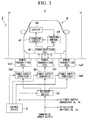
- FIG. 1 is a system structure view showing the mechanism structure of a vehicle electric power supply system A according to an embodiment of the present invention.
- this vehicle electric power supply system A supplies electric power wirelessly to a vehicle M that is positioned within an electric power supply area X.
- a plurality of power-transmitting coils i.e., power-transmitting devices 1a1, 1a2, and 1a3 are provided within the electric power supply area X.
- a power-receiving coil (i.e., a power-receiving device) m1 is provided in the vehicle M.
- the power-receiving coil m1 is provided in a bottom portion of the vehicle M such that the power-receiving coil will face towards the power-transmitting coil 1a1 and the like.
- the power-receiving coil m1 has substantially the same coil diameter as the power-transmitting coil 1a1 and the like, and receives AC power wirelessly by being electromagnetically coupled to the power-transmitting coil 1a1 and the like.
- the vehicle electric power supply system A is a power supply system in which power is supplied wirelessly to the vehicle M as a result of the power-transmitting coil 1a1 and the like being electromagnetically coupled to the power-receiving coil m1 of the vehicle M.
- the supplying of power wirelessly from the power-transmitting coil 1a1 and the like in the vehicle electric power supply system A to the power-receiving coil m1 is performed based on magnetic resonance.
- a resonance capacitor (not shown) that forms part of a resonance circuit is connected to both the power-transmitting coil 1a1 and the like and the power-receiving coil m1.
- the electrostatic capacitance of the resonance capacitor is set such that the resonance frequency of the resonance circuit on the power supply side, which is provided with the power-transmitting coil 1a1 and the like and with the resonance capacitor, be the same as the resonance frequency of the resonance circuit on the power receiving side, which is provided with the power-receiving coil m1 and with the resonance capacitor.
- the vehicle M is provided with a charging circuit m2, a battery m3, and a charging control unit m4.
- the power-receiving coil m1 outputs AC power (i.e. received power) that it has received from the power-transmitting coil 1a1 to the charging circuit m2.
- the charging circuit m2 is a power conversion circuit (i.e., a converter) that, based on charging control signals that the charging circuit m2 receives from the charging control unit m4, converts the received power into DC power that it then supplies to the battery m3. Namely, based on the charging control signals, the charging circuit m2 charges the battery m3 by supplying charging current to the battery m3 in accordance with the charged state of the battery m3.
- the battery m3 is the source of drive power for the vehicle M.
- the battery m3 is a rechargeable battery that is capable of storing sufficient power and, for example, is a lithium-ion rechargeable battery or a nickel-hydrogen rechargeable battery or the like.
- the battery m3 is charged by the DC current supplied from the charging circuit m2, and also supplies (i.e., discharges) traveling drive power to a drive power converter (not shown).
- the charging control unit m4 is a control device that controls the power conversion operations of the charging circuit m2 and controls the charging of the battery m3.
- the charging control unit m4 When the charging control unit m4 detects, on the basis, for example, of changes in the voltage between the terminals of the power receiving coil m1, that the power-receiving coil m1 has received AC power from the power-supply coil 1a1 and the like, the charging control unit m4 causes the charging circuit m2 to operate so as to cause the battery m3 to be charged with DC power.
- the power-transmitting coils 1a1, 1a2, and 1a3 are set in positions that are mutually different from each other within the electric power supply area X, which is a predetermined area that is established on the road surface along which the vehicle M travels. More specifically, the power-transmitting coils 1a1, 1a2, and 1a3 are placed apart from each other in the vehicle transverse direction of the vehicle M. The power-transmitting coil 1a1 is placed in the center of the road surface, while the power-transmitting coils 1a2 and 1a3 are placed on either side of the power-transmitting coil 1a1 and at a distance therefrom. The power-transmitting coils 1a1, 1a2, and 1a3 are embedded in the road adjacent to the road surface. Note that the number and placement of the power-transmitting coils described above are merely examples thereof, and the present invention is not limited to these examples.
- a power supply converter 3a is a device that, based on control signals that the power supply converter 3a receives from a control device 4 (i.e., position detecting device, control device), supplies AC power to the power-transmitting coil 1a1 and the like for the power-transmitting coils to use when they supply power. More specifically, the power supply converter 3a supplies power supply AC power via a selector switch 2a to any one of the power-transmitting coils 1a1, 1a2, and 1a3.
- the power supply converter 3a converts 50 Hz or 60 Hz commercial power into AC power of a frequency that is suitable for supplying power to the vehicle M (for example, between several hundred Hz and several MHz), and then outputs this power to the respective power-transmitting coils 1a1 and the like.
- the selector switch 2a is a device that, based on control signals that the selector switch 2a receives from the control device 4, switches the circuit that is electrically connected to the power supply converter 3a.
- the selector switch 2a is designed such that it can be electrically connected to any one of the power-transmitting coils 1a1, 1a2, and 1a3. By providing the selector switch 2a, it is not necessary to provide a dedicated power supply converter 3a for each one of the power-transmitting coils 1a1, 1a2, and 1a3. As a consequence of this, it is possible to increase the functionality and the efficiency of the structural components and control system of the vehicle electric power supply system A.
- the control device 4 detects the position of the power-receiving coil m1 within the electric power supply area X and, based on the results of these detections, selects from among the plurality of power-transmitting coils 1a1, 1a2, and 1a3 the power-transmitting coil 1a1 that is located in a position that corresponds to the power-receiving coil m1. The control device 4 then causes power to be supplied wirelessly from the selected power-transmitting coil 1a1.
- control device 4 when the control device 4 detects a position signal for the power-receiving coil m1, the control device 4 switches the selector switch 2a such that the power-transmitting coil 1a1 that is located in the optimum position to supply power wirelessly is selected, and then causes AC power from the power supply converter 3 a to be supplied to the selected power-transmitting coil 1a1.
- This control device 4 corresponds to the position detecting device and control device of the vehicle electric power supply system A.
- the control device 4 uses the power-transmitting coil 1a1 and the like and the power-receiving coil m1 as a position detecting device. More specifically, by diverting both the power-transmitting coil 1a1 and the like and the power-receiving coil m1 for the purpose of performing signal transmissions, wireless communication between the control device 4 and the charging control unit m4 is made possible via the power-transmitting coil 1a1 and the like and the power-receiving coil m1.
- the control device 4 and the charging control unit m4 function as an antenna for wireless communication
- the control device 4 and the charging control unit m4 function as communication devices that employ this antenna.
- This wireless communication can also be used to determine the stopped state of the vehicle M within a stopping area, or to verify before a power supply commences whether or not it is necessary for power to actually be supplied, or to transmit and receive transaction fee information relating to the supplying of power.
- the control device 4 may detect the position of the power-receiving coil m1 within the electric power supply area X based on the amount of charged power per unit time that is stored in the battery m3. For example, in order to seek the position of the power-receiving coil m1, the control device 4 switches the selector switch 2a at a regular predetermined interval so as to supply power sequentially to the power-transmitting coils 1a1, 1a2, and 1a3.
- the charging control unit m4 calculates the amount of charged power per unit time that has been stored in the battery m3 within each of the aforementioned regular predetermined intervals by monitoring the level of the power charge in the battery m3, and then transmits information about the power-transmitting coil having the greatest charging efficiency to the control device 4.
- the control device 4 is able to detect the position of the power-receiving coil m1 from the above-described information (namely, the information about the power-transmitting coil having the greatest power supplying efficiency)
- the control device 4 Based on the results of the detection of the position of the power-receiving coil m1, the control device 4 selects from among the plurality of power-transmitting coils 1a1, 1a2, and 1a3 the power-transmitting coil 1a1 that is located in a position that corresponds to the power-receiving coil m1, and causes power to be supplied wirelessly from this selected power-transmitting coil 1a1.
- control device 4 when the control device 4 acquires via wireless communication with the charging control unit m4 information relating to the position of the power-receiving coil m1 that is installed in the vehicle M, the control device 4 associates the position information for the power-receiving coil m1 with the placement information for the power-transmitting coil 1a1 and the like that has been stored in it in advance, and then selects the power-transmitting coil (i.e., the power-transmitting coil 1a1) that is located closest to the power-receiving coil m1.
- the control device 4 associates the position information for the power-receiving coil m1 with the placement information for the power-transmitting coil 1a1 and the like that has been stored in it in advance, and then selects the power-transmitting coil (i.e., the power-transmitting coil 1a1) that is located closest to the power-receiving coil m1.
- control device 4 when the control device 4 has acquired information relating to the position of the power-receiving coil m1 based on the amount of charged power per unit time that has been stored in the battery m3, then the control device 4 simply selects the power-transmitting coil (i.e., the power-transmitting coil 1a1) that has the greatest power supply efficiency.
- FIG. 2 is a typical diagram showing an example of the layout of the vehicle electric power supply system A of an embodiment of the present invention.
- FIG. 2 shows a case in which the electric power supply area X of this vehicle electric power supply system A is established, for example, in a vehicle stopping bay on a road.
- This electric power supply area X is set to a size that enables a plurality of vehicles M to be able to stop therein (for example, to a size that enables three passenger vehicles to stop therein), and such that any type of vehicle M that travels along the road is able to stop therein.
- the position of the power-receiving coil m1 in the foremost vehicle M and the positions of the power-receiving coils m1 in the vehicles M behind that vehicle are mutually different from each other.
- power-transmitting coils 1a1, 1a2, and 1a3 In addition to the power-transmitting coils 1a1, 1a2, and 1a3, power-transmitting coils 1b1, 1b2, and 1b3 and power-transmitting coils 1c1, 1c2, and 1c3 are also provided in the electric power supply area X. Note that the number and placement of these power-transmitting coils are merely examples thereof, and the present invention is not limited to these examples. For example, in the case of an electric power supply area X that is formed in a road stopping bay, it is also possible for a plurality of power-transmitting coils to be arranged at predetermined spacings in a matrix layout.
- a selector switch 2b and a power supply converter 3b that correspond to the power-transmitting coils 1b1, 1b2, and 1b3, and a selector switch 2c and a power supply converter 3c that correspond to the power-transmitting coils 1c1, 1c2, and 1 c3 are each provided in the electric power supply area X, and these are electrically connected to the control device 4.
- the control device 4 When the control device 4 has detected the positions of the plurality of power-receiving coils m1 within the electric power supply area X using the above-described position detecting device, then based on the results of this position detection, the control device 4 selects from among the plurality of power-transmitting coil 1a1 and the like the respective power-transmitting coils (namely, the power-transmitting coil 1a1, the power-transmitting coil 1b3, and the power-transmitting coil 1c2 in FIG. 2 ) that are located in positions that correspond to each of the plurality of power-receiving coils m1, and then causes power to be supplied wirelessly from the selected power-transmitting coils. As a result of this, power can be wirelessly supplied simultaneously to the plurality of vehicles M that are positioned within the electric power supply area X.
- the electric power supply area X is set within a vehicle stopping bay on a road. Accordingly, because the position where a vehicle M stops within the electric power supply area X depends on the driving action of the driver, these stopping positions are not consistently the same. Moreover, because any type of vehicle M that is traveling along the road is able to stop in the electric power supply area X, the positions of the power-receiving coils m1 in the vehicles M are different in each vehicle M.
- the AC power that is transmitted wirelessly from the power-transmitting coil 1a1 and the like to the power-receiving coil m1 is at its maximum when the power-receiving coil m1 is directly above and facing directly towards the power-transmitting coil 1a1 and the like, namely, when the power-receiving coil m1 and the power-transmitting coil 1a1 and the like are at their closest to each other.
- the power-receiving coil m1 cannot be expected to be situated so as to face directly towards a predetermined power-transmitting coil 1a1 and the like.
- the relative positions between a power-receiving coil m1 and a predetermined power-transmitting coil 1a1 or the like will not always be the same because of the inconsistent stopping positions of the vehicle M. Because of this, in the vehicle electric power supply system A, the plurality of power-transmitting coils 1a1 and the like are installed in mutually different positions within the electric power supply area X.
- the control device 4 constantly monitors whether or not a vehicle M is within the electric power supply area X by attempting to communicate wirelessly with the charging control unit m4 via the power-receiving coil m1 in the vehicle M using the power-transmitting coil 1a1 and the like as an antenna. For example, if there is no communication connection with the charging control unit m4, the control device 4 determines that no vehicle M has stopped within the electric power supply area X. In contrast, if there is a communication connection with the charging control unit m4, the control device 4 determines that a vehicle M has stopped within the electric power supply area X.
- the control device 4 When the control device 4 has determined that a vehicle M has stopped within the electric power supply area X, the control device 4 detects the position of the power-receiving coil m1 of the vehicle M. More specifically, information relating to the position of the power-receiving coil m1 that is installed in the vehicle M is transmitted and received by means of wireless communication between the control device 4 and the charging control unit m4 via the power-transmitting coil 1a1 and the like and the power-receiving coil m1, so that the position of the power-receiving coil m1 within the electric power supply area X is detected.
- the selector switch 2a and the like is switched at regular predetermined intervals such that power is supplied sequentially to the power-transmitting coils 1a1, 1a2, and 1a3, so that the position of the power-receiving coil m1 within the electric power supply area X is detected based on the amount of charged power per unit time that is actually stored in the battery m3.
- the position of the power-receiving coil m1 within the electric power supply area X is also possible to detect the position of the power-receiving coil m1 within the electric power supply area X using both of these methods.
- information relating to the position of the power-receiving coil m1 that is installed in the vehicle M is transmitted and received firstly by wireless communication, and approximate position information for the power-receiving coil m1 (i.e., information such as the fact that the power receiving coil m1 is located on the right side of the vehicle body) is exchanged.
- the position of the power-receiving coil m1 can be detected both accurately and in a short time by comparing the power-transmitting coils 1b1 and 1b2 that correspond to this position of the power receiving coil m1 with the amount of charged power per unit time that is stored in the battery m3. Namely, compared to the retrieval time when the position of the power-receiving coil m1 is accurately detected by sequentially supplying power to the power-transmitting coils 1b1, 1b2, and 1b3 right from the start, the retrieval time can be shortened by initially narrowing a retrieval range down to a retrieval range that is estimated based on approximate information for the power-receiving coil m1.
- the control device 4 selects from among the plurality of power-transmitting coils 1a1 and the like the power-transmitting coil 1a1 or the like that is located at a position that corresponds to the power-receiving coil m1, and then causes power to be supplied wirelessly from the selected power-transmitting coil 1a1 and the like. For example, if the control device 4 has detected that the power-receiving coil m1 of the foremost vehicle M shown in FIG.
- control device 4 selects this power-transmitting coil 1a1 and, by then switching the selector switch2a, the control device 4 causes power to be supplied from the power supply converter 3a to the power-transmitting coil 1a1.
- the power-receiving coil m1 of the vehicle M is electromagnetically coupled to the power-transmitting coil 1a1.
- the AC power that is supplied from each power supply converter 3a to the power-transmitting coil 1a1 is wirelessly transmitted from the power-transmitting coil 1a1 to the power-receiving coil m1 of the vehicle M.
- magnetic resonance is used. Because of this, the transmission efficiency of the AC power that is wirelessly transmitted from the power-transmitting coil 1a1 and the like to the power-receiving coil m1 is high.
- the control device 4 continues the wireless power supply to the vehicle M via the power-transmitting coil 1a1.
- the control device 4 determines that the vehicle M has moved out of the electric power supply area X and causes the supplying of power to the power-transmitting coil 1a1 to cease. Thereafter, the control device 4 returns to its initial standby state, and monitors whether or not a vehicle M stops within the electric power supply area X.
- the present embodiment it is possible to supply power wirelessly for a predetermined time to a vehicle M that has stopped within a stopping bay on a road where an electric power supply area X has been established by utilizing the fact that the vehicle M is stopped. Accordingly, according to the present embodiment, it is possible to supply power to the vehicle M at a particular location partway through the journey of the vehicle M. Namely, it is possible to both encourage the public acceptance of a vehicle M which uses electric power as a travel power source and improve the convenience of the vehicle M.
- the vehicle electric power supply system A that supplies power wirelessly to a vehicle M that is positioned within the electric power supply area X has a power-receiving coil m1 that is provided in the vehicle M, a plurality of power-transmitting coils 1a1 and the like that are provided at mutually different positions within the electric power supply area X, and a control device 4 that is equipped with a position detecting device that detects the position of the power-receiving coil m1 within the power supply area X, and with a control unit that, based on detection results from this position detecting device, selects from among the plurality of power-transmitting coils 1a1 and the like the power-transmitting coil 1a1 or the like that is located in a position that corresponds to the power-receiving coil m1, and then causes power to be supplied wirelessly from the selected power-transmitting coil 1a1.
- a plurality of electric power supplying devices are provided within an electric power supply area, and the position of a power-receiving device provided in a vehicle within the electric power supply area is detected.
- a ... Vehicle electric power supply system M ... Vehicle, m1 ... Power-receiving coil (Power-receiving device), X ... Electric power supply area, 1a1, 1a2, 1a3, 1b1, 1b2, 1b3, 1c1, 1c2, 1c3 ... Power-transmitting coils (Power-transmitting devices), 4 ... Control device (Position detecting device, Control device)
Landscapes
- Engineering & Computer Science (AREA)
- Power Engineering (AREA)
- Transportation (AREA)
- Mechanical Engineering (AREA)
- Computer Networks & Wireless Communication (AREA)
- Charge And Discharge Circuits For Batteries Or The Like (AREA)
- Electric Propulsion And Braking For Vehicles (AREA)
- Current-Collector Devices For Electrically Propelled Vehicles (AREA)
Abstract
Description
- The present invention relates to a vehicle electric power supply system. Priority is claimed on Japanese Patent Application No.
2011-203318, filed September 16, 2011 - It is sometimes difficult for vehicles such as hybrid vehicles and electric vehicles to travel long distances because of problems such as the performance of the mounted batteries and the like. Because of this, in recent years, in addition to supplying electric power to such batteries at users' homes and the like, it has been proposed that electric power supply areas be provided in a variety of locations along routes traveled by vehicles such as, for example, road stops, gas stations, hill slopes, and intersections and the like. For example, in Patent document 1 a vehicle electric power supply system is disclosed that supplies power wirelessly to a vehicle by utilizing traffic signals.
- [Patent document 1] Japanese Patent Application First Publication No.
2010-193657 - When electric power is being supplied wirelessly, the positional relationship between the power-receiving device provided in the vehicle and the power-transmitting device provided within the electric power supply area affects the efficiency of the electric power supply. For example, in locations where the position of the vehicle is more or less fixed, such as the parking space of a private home, there is no problem with the electric power supply efficiency. However, as in the aforementioned conventional technology, when electric power is supplied wirelessly while a vehicle is actually traveling, then it is easy for the position of the vehicle within the electric power supply area to be arbitrarily decided depending on the will of the driver. Because of this, positional mismatching between the power-receiving device and the power-transmitting device increases and this causes the electric power supply efficiency to deteriorate. Moreover, in some cases, the position where the power-receiving device is installed in the vehicle may differ depending on the type of vehicle, i.e., depending on whether the vehicle is a passenger vehicle or a truck or the like. Because of this, positional mismatching between the power-receiving device and the power-transmitting device increases and cases such as this also cause the electric power supply efficiency to deteriorate.
- The present invention was conceived in view of the above-described problems and it is an object thereof to provide a vehicle electric power supply system that is able to suppress any deterioration in the electric power supply efficiency.
- The present invention employs the following structure as a means of solving the above-described problems. A first aspect of the present invention is a vehicle electric power supply system that supplies electric power wirelessly to a vehicle that is positioned within an electric power supply area. This vehicle electric power supply system has a power-receiving device that is provided in the vehicle; a plurality of power-transmitting devices that are provided at mutually different positions within the electric power supply area; a position detecting device that detects the position of the power-receiving device within the electric power supply area; and a control device that, based on detection results from the position detecting device, selects from among the plurality of power-transmitting devices the power-transmitting device that is located in a position that corresponds to the power-receiving device, and then causes power to be supplied wirelessly from the selected power-transmitting device.
- A second aspect of the present invention is the vehicle electric power supply system according to the above-described first aspect in which, based on the detection results from the position detecting device, the control device selects from among the plurality of power-transmitting devices the power-transmitting device that is located in the closest position to the power-receiving device, and then causes power to be supplied wirelessly from the selected power-transmitting device.
- A third aspect of the present invention is the vehicle electric power supply system according to the above-described first or second aspects in which, when the position detecting device has detected the positions of a plurality of the power-receiving devices within the electric power supply area, then based on the detection results from the position detecting device, the control device selects from among the plurality of power-transmitting devices the respective power-transmitting devices that are placed in positions that correspond to each one of the plurality of power-receiving devices, and causes power to be supplied wirelessly from the selected power-transmitting devices.
- A fourth aspect of the present invention is the vehicle electric power supply system according to any one of the above-described first through third aspects in which the power-transmitting devices are provided with power-transmitting coils, and the power-receiving devices are provided with power-receiving coils, and the power-transmitting devices transmit power wirelessly by causing their power-transmitting coils to be electromagnetically coupled with the power-receiving coils.
- A fifth aspect of the present invention is the vehicle electric power supply system according to the above-described fourth aspect in which the power-transmitting coils and the power-receiving coils are used as the position detecting device.
- According to the present invention, a plurality of power-transmitting devices are provided within an electric power supply area, and the position of a power-receiving device provided in the vehicle within the electric power supply area is detected. By doing this, it is possible to select from the plurality of power-transmitting devices the power- transmitting device that is located in the optimum position to supply electric power wirelessly, and to supply electric power using the selected power-transmitting device. As a result, it is possible to suppress any deterioration in the electric power supply efficiency.
-
- [
FIG. 1] FIG. 1 is a system structure view showing the mechanism structure of a vehicle electric power supply system according to an embodiment of the present invention. - [
FIG. 2] FIG. 2 is a typical view showing an example of the layout of a vehicle electric power supply system according to an embodiment of the present invention. - [
FIG. 3] FIG. 3 is a system structure view showing the mechanism structure of a vehicle electric power supply system according to another embodiment of the present invention. - Hereinafter, embodiments of the present invention will be described in detail with reference made to the drawings.
-
FIG. 1 is a system structure view showing the mechanism structure of a vehicle electric power supply system A according to an embodiment of the present invention. As is shown inFIG. 1 , this vehicle electric power supply system A supplies electric power wirelessly to a vehicle M that is positioned within an electric power supply area X. A plurality of power-transmitting coils (i.e., power-transmitting devices) 1a1, 1a2, and 1a3 are provided within the electric power supply area X. A power-receiving coil (i.e., a power-receiving device) m1 is provided in the vehicle M. - The power-receiving coil m1 is provided in a bottom portion of the vehicle M such that the power-receiving coil will face towards the power-transmitting coil 1a1 and the like. The power-receiving coil m1 has substantially the same coil diameter as the power-transmitting coil 1a1 and the like, and receives AC power wirelessly by being electromagnetically coupled to the power-transmitting coil 1a1 and the like. In other words, the vehicle electric power supply system A is a power supply system in which power is supplied wirelessly to the vehicle M as a result of the power-transmitting coil 1a1 and the like being electromagnetically coupled to the power-receiving coil m1 of the vehicle M.
- The supplying of power wirelessly from the power-transmitting coil 1a1 and the like in the vehicle electric power supply system A to the power-receiving coil m1 is performed based on magnetic resonance. Namely, a resonance capacitor (not shown) that forms part of a resonance circuit is connected to both the power-transmitting coil 1a1 and the like and the power-receiving coil m1. For example, the electrostatic capacitance of the resonance capacitor is set such that the resonance frequency of the resonance circuit on the power supply side, which is provided with the power-transmitting coil 1a1 and the like and with the resonance capacitor, be the same as the resonance frequency of the resonance circuit on the power receiving side, which is provided with the power-receiving coil m1 and with the resonance capacitor.
- In addition to the power-receiving coil m1, the vehicle M is provided with a charging circuit m2, a battery m3, and a charging control unit m4. The power-receiving coil m1 outputs AC power (i.e. received power) that it has received from the power-transmitting coil 1a1 to the charging circuit m2. The charging circuit m2 is a power conversion circuit (i.e., a converter) that, based on charging control signals that the charging circuit m2 receives from the charging control unit m4, converts the received power into DC power that it then supplies to the battery m3. Namely, based on the charging control signals, the charging circuit m2 charges the battery m3 by supplying charging current to the battery m3 in accordance with the charged state of the battery m3.
- The battery m3 is the source of drive power for the vehicle M. The battery m3 is a rechargeable battery that is capable of storing sufficient power and, for example, is a lithium-ion rechargeable battery or a nickel-hydrogen rechargeable battery or the like. The battery m3 is charged by the DC current supplied from the charging circuit m2, and also supplies (i.e., discharges) traveling drive power to a drive power converter (not shown). The charging control unit m4 is a control device that controls the power conversion operations of the charging circuit m2 and controls the charging of the battery m3. When the charging control unit m4 detects, on the basis, for example, of changes in the voltage between the terminals of the power receiving coil m1, that the power-receiving coil m1 has received AC power from the power-supply coil 1a1 and the like, the charging control unit m4 causes the charging circuit m2 to operate so as to cause the battery m3 to be charged with DC power.
- The power-transmitting coils 1a1, 1a2, and 1a3 are set in positions that are mutually different from each other within the electric power supply area X, which is a predetermined area that is established on the road surface along which the vehicle M travels. More specifically, the power-transmitting coils 1a1, 1a2, and 1a3 are placed apart from each other in the vehicle transverse direction of the vehicle M. The power-transmitting coil 1a1 is placed in the center of the road surface, while the power-transmitting coils 1a2 and 1a3 are placed on either side of the power-transmitting coil 1a1 and at a distance therefrom. The power-transmitting coils 1a1, 1a2, and 1a3 are embedded in the road adjacent to the road surface. Note that the number and placement of the power-transmitting coils described above are merely examples thereof, and the present invention is not limited to these examples.
- A
power supply converter 3a is a device that, based on control signals that thepower supply converter 3a receives from a control device 4 (i.e., position detecting device, control device), supplies AC power to the power-transmitting coil 1a1 and the like for the power-transmitting coils to use when they supply power. More specifically, thepower supply converter 3a supplies power supply AC power via aselector switch 2a to any one of the power-transmitting coils 1a1, 1a2, and 1a3. Thepower supply converter 3a converts 50 Hz or 60 Hz commercial power into AC power of a frequency that is suitable for supplying power to the vehicle M (for example, between several hundred Hz and several MHz), and then outputs this power to the respective power-transmitting coils 1a1 and the like. - The
selector switch 2a is a device that, based on control signals that theselector switch 2a receives from thecontrol device 4, switches the circuit that is electrically connected to thepower supply converter 3a. Theselector switch 2a is designed such that it can be electrically connected to any one of the power-transmitting coils 1a1, 1a2, and 1a3. By providing theselector switch 2a, it is not necessary to provide a dedicatedpower supply converter 3a for each one of the power-transmitting coils 1a1, 1a2, and 1a3. As a consequence of this, it is possible to increase the functionality and the efficiency of the structural components and control system of the vehicle electric power supply system A. - The
control device 4 detects the position of the power-receiving coil m1 within the electric power supply area X and, based on the results of these detections, selects from among the plurality of power-transmitting coils 1a1, 1a2, and 1a3 the power-transmitting coil 1a1 that is located in a position that corresponds to the power-receiving coil m1. Thecontrol device 4 then causes power to be supplied wirelessly from the selected power-transmitting coil 1a1. Namely, when thecontrol device 4 detects a position signal for the power-receiving coil m1, thecontrol device 4 switches theselector switch 2a such that the power-transmitting coil 1a1 that is located in the optimum position to supply power wirelessly is selected, and then causes AC power from thepower supply converter 3 a to be supplied to the selected power-transmitting coil 1a1. Thiscontrol device 4 corresponds to the position detecting device and control device of the vehicle electric power supply system A. - The
control device 4 uses the power-transmitting coil 1a1 and the like and the power-receiving coil m1 as a position detecting device. More specifically, by diverting both the power-transmitting coil 1a1 and the like and the power-receiving coil m1 for the purpose of performing signal transmissions, wireless communication between thecontrol device 4 and the charging control unit m4 is made possible via the power-transmitting coil 1a1 and the like and the power-receiving coil m1. Via this wireless communication, information relating to the position of the power-receiving coil m1 that is installed in the vehicle M is transmitted and received between thecontrol device 4 and the charging control unit m4, and the position of the power-receiving coil m1 within the electric power supply area X is detected. In this case, the power-transmitting coil 1a1 and the like and the power-receiving coil m1 function as an antenna for wireless communication, and thecontrol device 4 and the charging control unit m4 function as communication devices that employ this antenna. This wireless communication can also be used to determine the stopped state of the vehicle M within a stopping area, or to verify before a power supply commences whether or not it is necessary for power to actually be supplied, or to transmit and receive transaction fee information relating to the supplying of power. - The
control device 4 may detect the position of the power-receiving coil m1 within the electric power supply area X based on the amount of charged power per unit time that is stored in the battery m3. For example, in order to seek the position of the power-receiving coil m1, thecontrol device 4 switches theselector switch 2a at a regular predetermined interval so as to supply power sequentially to the power-transmitting coils 1a1, 1a2, and 1a3. The charging control unit m4 calculates the amount of charged power per unit time that has been stored in the battery m3 within each of the aforementioned regular predetermined intervals by monitoring the level of the power charge in the battery m3, and then transmits information about the power-transmitting coil having the greatest charging efficiency to thecontrol device 4. In the case of wireless power supply, the smaller the positional mismatching with the power-receiving coil m1, the greater the power supplying efficiency of the power-transmitting coil. Because of this, thecontrol device 4 is able to detect the position of the power-receiving coil m1 from the above-described information (namely, the information about the power-transmitting coil having the greatest power supplying efficiency) - Based on the results of the detection of the position of the power-receiving coil m1, the
control device 4 selects from among the plurality of power-transmitting coils 1a1, 1a2, and 1a3 the power-transmitting coil 1a1 that is located in a position that corresponds to the power-receiving coil m1, and causes power to be supplied wirelessly from this selected power-transmitting coil 1a1. More specifically, when thecontrol device 4 acquires via wireless communication with the charging control unit m4 information relating to the position of the power-receiving coil m1 that is installed in the vehicle M, thecontrol device 4 associates the position information for the power-receiving coil m1 with the placement information for the power-transmitting coil 1a1 and the like that has been stored in it in advance, and then selects the power-transmitting coil (i.e., the power-transmitting coil 1a1) that is located closest to the power-receiving coil m1. Moreover, when thecontrol device 4 has acquired information relating to the position of the power-receiving coil m1 based on the amount of charged power per unit time that has been stored in the battery m3, then thecontrol device 4 simply selects the power-transmitting coil (i.e., the power-transmitting coil 1a1) that has the greatest power supply efficiency. -
FIG. 2 is a typical diagram showing an example of the layout of the vehicle electric power supply system A of an embodiment of the present invention.FIG. 2 shows a case in which the electric power supply area X of this vehicle electric power supply system A is established, for example, in a vehicle stopping bay on a road. This electric power supply area X is set to a size that enables a plurality of vehicles M to be able to stop therein (for example, to a size that enables three passenger vehicles to stop therein), and such that any type of vehicle M that travels along the road is able to stop therein. For example, as is shown inFIG. 2 , the position of the power-receiving coil m1 in the foremost vehicle M and the positions of the power-receiving coils m1 in the vehicles M behind that vehicle are mutually different from each other. - In addition to the power-transmitting coils 1a1, 1a2, and 1a3, power-transmitting coils 1b1, 1b2, and 1b3 and power-transmitting coils 1c1, 1c2, and 1c3 are also provided in the electric power supply area X. Note that the number and placement of these power-transmitting coils are merely examples thereof, and the present invention is not limited to these examples. For example, in the case of an electric power supply area X that is formed in a road stopping bay, it is also possible for a plurality of power-transmitting coils to be arranged at predetermined spacings in a matrix layout. Moreover, a
selector switch 2b and apower supply converter 3b that correspond to the power-transmitting coils 1b1, 1b2, and 1b3, and aselector switch 2c and apower supply converter 3c that correspond to the power-transmitting coils 1c1, 1c2, and 1 c3 are each provided in the electric power supply area X, and these are electrically connected to thecontrol device 4. - When the
control device 4 has detected the positions of the plurality of power-receiving coils m1 within the electric power supply area X using the above-described position detecting device, then based on the results of this position detection, thecontrol device 4 selects from among the plurality of power-transmitting coil 1a1 and the like the respective power-transmitting coils (namely, the power-transmitting coil 1a1, the power-transmitting coil 1b3, and the power-transmitting coil 1c2 inFIG. 2 ) that are located in positions that correspond to each of the plurality of power-receiving coils m1, and then causes power to be supplied wirelessly from the selected power-transmitting coils. As a result of this, power can be wirelessly supplied simultaneously to the plurality of vehicles M that are positioned within the electric power supply area X. - An operating sequence of the vehicle electric power supply system A having the above-described structure will be described below. In the vehicle electric power supply system A, the electric power supply area X is set within a vehicle stopping bay on a road. Accordingly, because the position where a vehicle M stops within the electric power supply area X depends on the driving action of the driver, these stopping positions are not consistently the same. Moreover, because any type of vehicle M that is traveling along the road is able to stop in the electric power supply area X, the positions of the power-receiving coils m1 in the vehicles M are different in each vehicle M.
- The AC power that is transmitted wirelessly from the power-transmitting coil 1a1 and the like to the power-receiving coil m1 is at its maximum when the power-receiving coil m1 is directly above and facing directly towards the power-transmitting coil 1a1 and the like, namely, when the power-receiving coil m1 and the power-transmitting coil 1a1 and the like are at their closest to each other. However, because of the circumstances described above, the power-receiving coil m1 cannot be expected to be situated so as to face directly towards a predetermined power-transmitting coil 1a1 and the like. In other words, the relative positions between a power-receiving coil m1 and a predetermined power-transmitting coil 1a1 or the like will not always be the same because of the inconsistent stopping positions of the vehicle M. Because of this, in the vehicle electric power supply system A, the plurality of power-transmitting coils 1a1 and the like are installed in mutually different positions within the electric power supply area X.
- The
control device 4 constantly monitors whether or not a vehicle M is within the electric power supply area X by attempting to communicate wirelessly with the charging control unit m4 via the power-receiving coil m1 in the vehicle M using the power-transmitting coil 1a1 and the like as an antenna. For example, if there is no communication connection with the charging control unit m4, thecontrol device 4 determines that no vehicle M has stopped within the electric power supply area X. In contrast, if there is a communication connection with the charging control unit m4, thecontrol device 4 determines that a vehicle M has stopped within the electric power supply area X. - When the
control device 4 has determined that a vehicle M has stopped within the electric power supply area X, thecontrol device 4 detects the position of the power-receiving coil m1 of the vehicle M. More specifically, information relating to the position of the power-receiving coil m1 that is installed in the vehicle M is transmitted and received by means of wireless communication between thecontrol device 4 and the charging control unit m4 via the power-transmitting coil 1a1 and the like and the power-receiving coil m1, so that the position of the power-receiving coil m1 within the electric power supply area X is detected. Alternatively, theselector switch 2a and the like is switched at regular predetermined intervals such that power is supplied sequentially to the power-transmitting coils 1a1, 1a2, and 1a3, so that the position of the power-receiving coil m1 within the electric power supply area X is detected based on the amount of charged power per unit time that is actually stored in the battery m3. - Alternatively, it is also possible to detect the position of the power-receiving coil m1 within the electric power supply area X using both of these methods. For example, in the case of the second vehicle M shown in
FIG. 2 , information relating to the position of the power-receiving coil m1 that is installed in the vehicle M is transmitted and received firstly by wireless communication, and approximate position information for the power-receiving coil m1 (i.e., information such as the fact that the power receiving coil m1 is located on the right side of the vehicle body) is exchanged. Next, the position of the power-receiving coil m1 can be detected both accurately and in a short time by comparing the power-transmitting coils 1b1 and 1b2 that correspond to this position of the power receiving coil m1 with the amount of charged power per unit time that is stored in the battery m3. Namely, compared to the retrieval time when the position of the power-receiving coil m1 is accurately detected by sequentially supplying power to the power-transmitting coils 1b1, 1b2, and 1b3 right from the start, the retrieval time can be shortened by initially narrowing a retrieval range down to a retrieval range that is estimated based on approximate information for the power-receiving coil m1. - After the position of the power-receiving coil m1 within the electric power supply area X has been detected, based on the results of this detection, the
control device 4 selects from among the plurality of power-transmitting coils 1a1 and the like the power-transmitting coil 1a1 or the like that is located at a position that corresponds to the power-receiving coil m1, and then causes power to be supplied wirelessly from the selected power-transmitting coil 1a1 and the like. For example, if thecontrol device 4 has detected that the power-receiving coil m1 of the foremost vehicle M shown inFIG. 2 is positioned above or nearly above the power-transmitting coil 1a1, thecontrol device 4 selects this power-transmitting coil 1a1 and, by then switching the selector switch2a, thecontrol device 4 causes power to be supplied from thepower supply converter 3a to the power-transmitting coil 1a1. - The power-receiving coil m1 of the vehicle M is electromagnetically coupled to the power-transmitting coil 1a1. As a result of this, the AC power that is supplied from each
power supply converter 3a to the power-transmitting coil 1a1 is wirelessly transmitted from the power-transmitting coil 1a1 to the power-receiving coil m1 of the vehicle M. In the vehicle electric power supply system A, magnetic resonance is used. Because of this, the transmission efficiency of the AC power that is wirelessly transmitted from the power-transmitting coil 1a1 and the like to the power-receiving coil m1 is high. - During the period in which the
control device 4 is connected for communication with the charging control unit m4, thecontrol device 4 continues the wireless power supply to the vehicle M via the power-transmitting coil 1a1. When the connection for communication between thecontrol device 4 and the chargingcontrol unit m 4 is broken off, thecontrol device 4 determines that the vehicle M has moved out of the electric power supply area X and causes the supplying of power to the power-transmitting coil 1a1 to cease. Thereafter, thecontrol device 4 returns to its initial standby state, and monitors whether or not a vehicle M stops within the electric power supply area X. - According to the above-described present embodiment, it is possible to supply power wirelessly for a predetermined time to a vehicle M that has stopped within a stopping bay on a road where an electric power supply area X has been established by utilizing the fact that the vehicle M is stopped. Accordingly, according to the present embodiment, it is possible to supply power to the vehicle M at a particular location partway through the journey of the vehicle M. Namely, it is possible to both encourage the public acceptance of a vehicle M which uses electric power as a travel power source and improve the convenience of the vehicle M.
- Moreover, according to the above-described present embodiment, the vehicle electric power supply system A that supplies power wirelessly to a vehicle M that is positioned within the electric power supply area X has a power-receiving coil m1 that is provided in the vehicle M, a plurality of power-transmitting coils 1a1 and the like that are provided at mutually different positions within the electric power supply area X, and a
control device 4 that is equipped with a position detecting device that detects the position of the power-receiving coil m1 within the power supply area X, and with a control unit that, based on detection results from this position detecting device, selects from among the plurality of power-transmitting coils 1a1 and the like the power-transmitting coil 1a1 or the like that is located in a position that corresponds to the power-receiving coil m1, and then causes power to be supplied wirelessly from the selected power-transmitting coil 1a1. As a consequence, it is possible to select from among the plurality of power-transmitting coils 1a1 and the like the power-transmitting coil 1a1 or the like that is located in the optimum position for supplying power wirelessly, and to then cause this power-transmitting coil 1a1 or the like to supply power. Accordingly, in the present embodiment, it is possible to achieve a vehicle electric power supply system A that is able to limit any reduction in the power supply efficiency even when a vehicle M is supplied with power wirelessly partway through its journey. - Note that the present invention is not limited to the above-described respective embodiments and, for example, the following variant examples may also be considered.
- (1) In the present embodiment, as is shown in
FIG. 2 , the power-transmitting coils 1a1 and the like, 1b1 and the like, and 1c1 and the like that are located within the power supply area X are embedded in the road at a predetermined distance from each other. However, the present invention is not limited to this. For example, the stopping positions of the vehicles M change depending on the respective sizes (i.e., vehicle lengths) of the foremost vehicle M and the vehicles M to the rear of that vehicle. Because of this, it is also possible for the power-transmitting coils 1a1 and the like of the rearward vehicles M to be embedded in the road surface, for example, at the same distance from each other as the length of the vehicle M having the shortest vehicle length. Furthermore, it is also possible to provide the selector switches 2a and the like and thepower supply converters 3a and the like at the same distances from each other respectively as the length of that shortest vehicle M, and to supply power wirelessly at intervals of this vehicle length. If the power-transmitting coils 1a1 and the like, 1b1 and the like, and 1c1 and the like are embedded at these comparatively short intervals, then even if a plurality of vehicles M having mutually different sizes (i.e., vehicle lengths) stop within the power supply area X, it is still possible for power to be supplied to each of these vehicles M. Note that the number of power-transmitting coils 1a1 and the like within the power supply area X is appropriately set in accordance with the location and environment and the like where the power supply area X is established. - (2) In the present embodiment, the power-transmitting coils 1a1 and the like are embedded in the road surface and the power-receiving coils m1 are provided in a base portion of the vehicles M, and the power-transmitting coils 1a1 and the like and the power-receiving coils m1 are placed opposite each other in a vertical direction. However, the present invention is not limited to this. For example, it is also possible for the power-receiving coil m1 to be provided in a side portion (i.e., in an entrance door) of the vehicle M, and for the power-transmitting coil 1a1 and the like to be provided on the shoulder of the road such that its center axis is horizontal and is also orthogonal to the axis of the traffic lane, and such that it faces the side portion (i.e., the entrance door) of the vehicle M. Moreover, it is also possible for the power-receiving coil m1 to be provided in the roof portion of the vehicle M and for the power-transmitting coil 1a1 and the like to be provided above the road so as to face the roof portion of the vehicle M.
- (3) In the present embodiment, as is shown in
FIG. 1 , thepower supply converter 3a supplies the AC power for the power supply to any one of the power-transmitting coils 1a1, 1a2, and 1a3 via theselector switch 2a. However, the present invention is not limited to this. For example, as is shown inFIG. 3 , it is also possible for independent power supply converters 3a1, 3a2, and 3a3 to be directly connected to the respective power-transmitting coils 1a1, 1a2, and 1a3, and for the 50 Hz or 60 Hz commercial power that is supplied to each of these power supply converters to be switched by theselector switch 2a. - (4) In the present embodiment, the power-transmitting coils 1a1 and the like and the power-receiving coils m1 are used as the position detecting device. However, the present invention is not limited to this. For example, instead of this, it is also possible for the vehicle electric power supply system A (i.e., the on-ground facility) and the vehicle M to be furnished with their own separate communication functions. For example, the use of known optical beacons or wireless communication instruments that employ radio waves and the like for the separate communication functions may also be considered. However, because it is only necessary for communication between the vehicle electric power supply system A (i.e., the on-ground facility) and the vehicle M, in other words, for communication over a comparatively short distance to be possible, it is also possible to employ individually designed communication systems for the separate communication functions. Moreover, it is also possible to design a system in which the stopping position and stopped state (i.e., attitude) of the vehicle M are detected by measuring the latitude and longitude of the vehicle M via GPS, or by embedding strain gauges in the road and then measuring the load thereon, or by measuring distance using a 3-D laser radar, and in which the position of the power-receiving coil m1 is then detected based on the results from such detections.
- (5) In the present embodiment, the position of the power-receiving coil m1 within the electric power supply area X is detected based on wireless communication between the
control device 4 and the charging control unit m4 via the power-transmitting coils 1a1 and the like and the power-receiving coil m1, or based on the amount of charged power per unit time that has accumulated in the battery m3, however, the present invention is not limited to this. For example, it is also possible to mount the power-receiving coil m1 in a predetermined position in the vehicle M (for example, in the position of the driver's seat in the front-rear direction, and in the position of the center of the vehicle in the left right direction), and to install 3-D laser radar or a stereo camera in a position that enables it to photograph the entire electric power supply area X (for example, in a position where it looks down diagonally from above over the electric power supply area X). By doing this, it is possible to detect the position of the vehicle from the photographed images by means of three-dimensional shape matching, and to thereby indirectly determine the position of the power-receiving coil m1. - (6) In the present embodiment, the electric power supply area X is established in a vehicle stopping bay on a road. However, the present invention is not limited to this. In addition to a road stopping bay, the various locations where the electric power supply area X can be established include, for example, areas in front of traffic signals that are located on roads (i.e., public roads), areas in front of railway level crossings, carparks in shopping centers, drive-through lanes in stores and the like, and stopping areas in gas stations and the like. Moreover, the present invention is not limited to public roads and private roads and the like, and the electric power supply area X may also be established on private land such as home carparks and the like.
- (7) In the present embodiment, power is supplied wirelessly to a vehicle M (i.e., to a stopped vehicle) that is positioned within the electric power supply area X without any preconditions being set. However, the present invention is not limited to this. For example, it is also possible to divert the power-transmitting coils 1a1 and the like and the power-receiving coils m1 for the purpose of performing signal transmissions so as to make wireless communication between the
control device 4 and the charging control unit m4 possible, or to use this wireless communication to verify the necessity of supplying power before the supplying of power commences, or to transmit and receive transaction fee information relating to the supplying of power. In this case, the power-transmitting coils 1a1 and the like and the power-receiving coils m1 function as an antenna for this wireless communication, and thecontrol device 4 and the charging control unit m4 function as communication devices that utilize this antenna. Moreover, it is not necessary to divert the power-transmitting coils 1a1 and the like and the power-receiving coils m1 for the purpose of performing signal transmissions, but it is possible to perform wireless communication using separately provided individual communication devices. - (8) In the present embodiment, a case is described in which the power that is supplied to the vehicle M is used to charge the battery m3. However, the present invention is not limited to this. For example, it is also possible for the power that is supplied to the vehicle M to be used to drive illumination devices or air-conditioning devices inside the vehicle M.
- According to the present invention, a plurality of electric power supplying devices are provided within an electric power supply area, and the position of a power-receiving device provided in a vehicle within the electric power supply area is detected. By doing this, it is possible to select from the plurality of power- transmitting devices the power- transmitting device that is located in the optimum position to supply electric power wirelessly, and to supply electric power using the selected power-transmitting device. As a result, it is possible to suppress any deterioration in the electric power supply efficiency.
- A ... Vehicle electric power supply system, M ... Vehicle, m1 ... Power-receiving coil (Power-receiving device), X ... Electric power supply area, 1a1, 1a2, 1a3, 1b1, 1b2, 1b3, 1c1, 1c2, 1c3 ... Power-transmitting coils (Power-transmitting devices), 4 ... Control device (Position detecting device, Control device)
Claims (12)
- A vehicle electric power supply system that supplies electric power wirelessly to a vehicle that is positioned within an electric power supply area, comprising:a power-receiving device that is provided in the vehicle;a plurality of power-transmitting devices that are provided at mutually different positions within the electric power supply area;a position detecting device that detects the position of the power-receiving device within the electric power supply area; anda control device that, based on detection results from the position detecting device, selects from among the plurality of power-transmitting devices the power-transmitting device that is located in a position that corresponds to the power-receiving device, and then causes power to be supplied wirelessly from the selected power-transmitting device.
- The vehicle electric power supply system according to claim 1, wherein, based on the detection results from the position detecting device, the control device selects from among the plurality of power-transmitting devices the power-transmitting device that is located in the closest position to the power-receiving device, and then causes power to be supplied wirelessly from the selected power-transmitting device.
- The vehicle electric power supply system according to claim 1, wherein, when the position detecting device has detected the positions of a plurality of the power-receiving devices within the electric power supply area,
then based on the detection results from the position detecting device, the control device selects from among the plurality of power-transmitting devices the respective power-transmitting devices that are placed in positions that correspond to each one of the plurality of power-receiving devices, and causes power to be supplied wirelessly from the selected power-transmitting devices. - The vehicle electric power supply system according to claim 2, wherein, when the position detecting device has detected the positions of a plurality of the power-receiving devices within the electric power supply area,
then based on the detection results from the position detecting device, the control device selects from among the plurality of power-transmitting devices the respective power-transmitting devices that are placed in positions that correspond to each one of the plurality of power-receiving devices, and causes power to be supplied wirelessly from the selected power-transmitting devices. - The vehicle electric power supply system according to claim 1, wherein the power-transmitting devices are provided with power-transmitting coils, and the power-receiving devices are provided with power-receiving coils, and
the power-transmitting devices transmit power wirelessly by causing their power-transmitting coils to be electromagnetically coupled with the power-receiving coils. - The vehicle electric power supply system according to claim 2, wherein the power-transmitting devices are provided with power-transmitting coils, and the power-receiving devices are provided with power-receiving coils, and
the power-transmitting devices transmit power wirelessly by causing their power-transmitting coils to be electromagnetically coupled with the power-receiving coils. - The vehicle electric power supply system according to claim 3, wherein the power-transmitting devices are provided with power-transmitting coils, and the power-receiving devices are provided with power-receiving coils, and
the power-transmitting devices transmit power wirelessly by causing their power-transmitting coils to be electromagnetically coupled with the power-receiving coils. - The vehicle electric power supply system according to claim 4, wherein the power-transmitting devices are provided with power-transmitting coils, and the power-receiving devices are provided with power-receiving coils, and
the power-transmitting devices transmit power wirelessly by causing their power-transmitting coils to be electromagnetically coupled with the power-receiving coils. - The vehicle electric power supply system according to claim 5, wherein the power-transmitting coils and the power-receiving coils are used as the position detecting device.
- The vehicle electric power supply system according to claim 6, wherein the power-transmitting coils and the power-receiving coils are used as the position detecting device.
- The vehicle electric power supply system according to claim 7, wherein the power-transmitting coils and the power-receiving coils are used as the position detecting device.
- The vehicle electric power supply system according to claim 8, wherein the power-transmitting coils and the power-receiving coils are used as the position detecting device.
Applications Claiming Priority (2)
| Application Number | Priority Date | Filing Date | Title |
|---|---|---|---|
| JP2011203318A JP5803475B2 (en) | 2011-09-16 | 2011-09-16 | Mobile vehicle power supply system |
| PCT/JP2012/073455 WO2013039143A1 (en) | 2011-09-16 | 2012-09-13 | Moving-vehicle electric power feeding system |
Publications (3)
| Publication Number | Publication Date |
|---|---|
| EP2757657A1 true EP2757657A1 (en) | 2014-07-23 |
| EP2757657A4 EP2757657A4 (en) | 2016-03-23 |
| EP2757657B1 EP2757657B1 (en) | 2021-02-24 |
Family
ID=47883362
Family Applications (1)
| Application Number | Title | Priority Date | Filing Date |
|---|---|---|---|
| EP12831164.4A Active EP2757657B1 (en) | 2011-09-16 | 2012-09-13 | Moving-vehicle electric power feeding system |
Country Status (5)
| Country | Link |
|---|---|
| US (2) | US9027723B2 (en) |
| EP (1) | EP2757657B1 (en) |
| JP (1) | JP5803475B2 (en) |
| CN (1) | CN103782489B (en) |
| WO (1) | WO2013039143A1 (en) |
Cited By (4)
| Publication number | Priority date | Publication date | Assignee | Title |
|---|---|---|---|---|
| WO2018024318A1 (en) * | 2016-08-02 | 2018-02-08 | Bayerische Motoren Werke Aktiengesellschaft | A method for providing an inductive-charging device into an existing driving-road, a respective inductive-charging device, a respective inductive-charging system and a respective automobile |
| EP3077247B1 (en) * | 2013-12-06 | 2018-06-20 | Bombardier Primove GmbH | Inductive power transfer for transferring electric energy to a vehicle |
| US10468897B2 (en) | 2016-10-14 | 2019-11-05 | International Business Machines Corporation | Wireless electric power sharing between vehicles |
| US20220348097A1 (en) * | 2021-04-30 | 2022-11-03 | Nd Industries, Inc. | Automated electric vehicle charging station |
Families Citing this family (43)
| Publication number | Priority date | Publication date | Assignee | Title |
|---|---|---|---|---|
| GB2485616A (en) * | 2010-11-22 | 2012-05-23 | Bombardier Transp Gmbh | Route for transferring electric energy to vehicles |
| JP5803475B2 (en) * | 2011-09-16 | 2015-11-04 | 株式会社Ihi | Mobile vehicle power supply system |
| GB2496433A (en) * | 2011-11-10 | 2013-05-15 | Bombardier Transp Gmbh | Inductively transferring energy to an electric vehicle |
| JP5716725B2 (en) * | 2012-11-21 | 2015-05-13 | トヨタ自動車株式会社 | Power transmission device and power transmission system |
| JP6124119B2 (en) * | 2013-03-29 | 2017-05-10 | パナソニックIpマネジメント株式会社 | Power feeding device and power receiving device |
| JP2014207758A (en) * | 2013-04-11 | 2014-10-30 | 富士通株式会社 | Server device, processing method thereof, information system, and processing method thereof |
| US9520748B2 (en) * | 2013-04-17 | 2016-12-13 | El Wha Llc | Systems and methods for providing wireless power to a power-receiving device, and related power-receiving devices |
| WO2014184864A1 (en) * | 2013-05-14 | 2014-11-20 | 株式会社Ihi | Contactless power transmission device and moving vehicle |
| US9187006B2 (en) * | 2013-09-05 | 2015-11-17 | Volkswagen Ag | Vehicle positioning for wireless charging systems |
| JP5979125B2 (en) * | 2013-12-11 | 2016-08-24 | トヨタ自動車株式会社 | Contactless power transmission equipment |
| CN104716749A (en) * | 2013-12-12 | 2015-06-17 | 深圳大学 | Distributed grid wireless power supply system and load end matched with same |
| DE102013227129B4 (en) * | 2013-12-23 | 2016-01-14 | Continental Automotive Gmbh | Method for detecting a relative position, method for wireless charging of a vehicle, orientation signal receiver and inductive charging device |
| JP6381209B2 (en) * | 2013-12-26 | 2018-08-29 | キヤノン株式会社 | Power transmission device, control method, and program |
| GB2521676B (en) * | 2013-12-31 | 2016-08-03 | Electric Road Ltd | System and method for powering an electric vehicle on a road |
| US9772401B2 (en) * | 2014-03-17 | 2017-09-26 | Qualcomm Incorporated | Systems, methods, and apparatus for radar-based detection of objects in a predetermined space |
| JP6057477B2 (en) * | 2014-10-15 | 2017-01-11 | 学校法人加計学園 岡山理科大学 | Non-contact power feeding device |
| KR101729159B1 (en) * | 2014-12-19 | 2017-04-25 | 한국 전기안전공사 | Vehicle guidance system using power charging voltage potential |
| JP6060195B2 (en) * | 2015-03-06 | 2017-01-11 | 本田技研工業株式会社 | Vehicle parking control device |
| US10116145B2 (en) * | 2015-10-16 | 2018-10-30 | uBeam Inc. | Performance adjustment for wireless power transfer devices |
| US10632852B2 (en) | 2015-11-13 | 2020-04-28 | Nio Usa, Inc. | Electric vehicle optical charging system and method of use |
| US20170136887A1 (en) * | 2015-11-13 | 2017-05-18 | NextEv USA, Inc. | Electric vehicle aerial vehicle charging system and method of use |
| US10532663B2 (en) | 2015-11-13 | 2020-01-14 | Nio Usa, Inc. | Electric vehicle overhead charging system and method of use |
| US10029551B2 (en) * | 2015-11-16 | 2018-07-24 | Kubota Corporation | Electric work vehicle, battery pack for electric work vehicle and contactless charging system |
| US20170182903A1 (en) * | 2015-12-26 | 2017-06-29 | Intel Corporation | Technologies for wireless charging of electric vehicles |
| EP3435519B1 (en) * | 2016-03-25 | 2021-02-17 | Fuji Corporation | Wireless power supply device |
| KR20240113985A (en) * | 2017-01-23 | 2024-07-23 | 나이키 이노베이트 씨.브이. | Wireless charging system with multi-coil scanning |
| JP6766690B2 (en) * | 2017-02-28 | 2020-10-14 | 株式会社Ihi | Ground side power supply device |
| US10675982B2 (en) | 2017-03-27 | 2020-06-09 | General Electric Company | System and method for inductive charging with improved efficiency |
| US10850634B2 (en) * | 2017-10-20 | 2020-12-01 | Toyota Motor Engineering & Manufacturing North America, Inc. | Multi-turn configurable grid charging coil |
| CN107757407A (en) * | 2017-10-30 | 2018-03-06 | 中车株洲电力机车有限公司 | A kind of intelligent charging method, system, equipment and computer-readable recording medium |
| JP7230422B2 (en) | 2018-10-19 | 2023-03-01 | トヨタ自動車株式会社 | DRIVING ASSIST DEVICE, DRIVING CONTROL SYSTEM FOR VEHICLE, DRIVING CONTROL METHOD, AND DRIVING CONTROL PROGRAM |
| US10903697B2 (en) * | 2019-03-19 | 2021-01-26 | Witricity Corporation | Methods and systems for multi-phase coil control |
| WO2022036244A1 (en) * | 2020-08-13 | 2022-02-17 | Clean Train Propulsion | Dynamic wireless power transfer system controlling multiple transmitter coils |
| JP7380525B2 (en) * | 2020-11-05 | 2023-11-15 | トヨタ自動車株式会社 | Travel control device, travel control program, and travel control system |
| JP7673457B2 (en) * | 2021-03-26 | 2025-05-09 | 株式会社Ihi | Power supply system for electric vehicle and power supply method for electric vehicle using power supply system |
| JP7596893B2 (en) * | 2021-03-30 | 2024-12-10 | 株式会社Ihi | Power supply equipment for electric vehicle, electric vehicle, and power supply method for electric vehicle |
| US11845347B2 (en) * | 2021-05-12 | 2023-12-19 | David Alan Copeland | Precision charging control of an untethered vehicle with a modular vehicle charging roadway |
| JPWO2023048166A1 (en) * | 2021-09-24 | 2023-03-30 | ||
| WO2023063200A1 (en) * | 2021-10-12 | 2023-04-20 | 本田技研工業株式会社 | Parking/stopping zone, replacement device, and autonomous traveling vehicle |
| US20230140116A1 (en) * | 2021-11-03 | 2023-05-04 | Rosen Aviation, Llc | Wireless charging system |
| DE102022132613A1 (en) * | 2022-12-08 | 2024-06-13 | Audi Aktiengesellschaft | Motor vehicle with a direct current electrical system |
| US12221003B1 (en) * | 2022-12-22 | 2025-02-11 | Integrated Roadways, Llc | Wireless charging system for a road |
| CN118801550B (en) * | 2024-09-14 | 2025-05-16 | 珠海格力电器股份有限公司 | Power supply method and clothes treatment equipment |
Family Cites Families (40)
| Publication number | Priority date | Publication date | Assignee | Title |
|---|---|---|---|---|
| US5573090A (en) * | 1994-05-05 | 1996-11-12 | H. R. Ross Industries, Inc. | Raodway-powered electric vehicle system having onboard power metering and communication channel features |
| US6421600B1 (en) * | 1994-05-05 | 2002-07-16 | H. R. Ross Industries, Inc. | Roadway-powered electric vehicle system having automatic guidance and demand-based dispatch features |
| US5669470A (en) * | 1994-05-05 | 1997-09-23 | H. R. Ross Industries, Inc. | Roadway-powered electric vehicle system |
| US6651566B2 (en) * | 2002-03-13 | 2003-11-25 | Ford Motor Company | Transportation system |
| JP4710314B2 (en) * | 2004-12-06 | 2011-06-29 | 日産自動車株式会社 | Road-to-vehicle power supply system |
| JP2006288034A (en) * | 2005-03-31 | 2006-10-19 | Matsushita Electric Ind Co Ltd | Power transmission / reception device |
| JP2008088889A (en) | 2006-10-02 | 2008-04-17 | Honda Motor Co Ltd | Bearing structure of control shaft in engine with variable stroke characteristics |
| WO2008051611A2 (en) * | 2006-10-25 | 2008-05-02 | Farkas Laszio | High power wireless resonant energy transfer system transfers energy across an airgap |
| JP4772744B2 (en) * | 2007-05-17 | 2011-09-14 | 昭和飛行機工業株式会社 | Signal transmission coil communication device for non-contact power feeding device |
| JP4453741B2 (en) * | 2007-10-25 | 2010-04-21 | トヨタ自動車株式会社 | Electric vehicle and vehicle power supply device |
| GB2461578A (en) * | 2008-07-04 | 2010-01-06 | Bombardier Transp Gmbh | Transferring electric energy to a vehicle |
| US8466654B2 (en) * | 2008-07-08 | 2013-06-18 | Qualcomm Incorporated | Wireless high power transfer under regulatory constraints |
| GB2463693A (en) * | 2008-09-19 | 2010-03-24 | Bombardier Transp Gmbh | A system for transferring electric energy to a vehicle |
| GB2463692A (en) * | 2008-09-19 | 2010-03-24 | Bombardier Transp Gmbh | An arrangement for providing a vehicle with electric energy |
| CN101764434B (en) * | 2008-12-22 | 2014-05-14 | 爱信艾达株式会社 | Power reception guidance device |
| JP2010183812A (en) * | 2009-02-09 | 2010-08-19 | Toyota Industries Corp | Resonance type non-contact charging system |
| JP5359353B2 (en) | 2009-02-19 | 2013-12-04 | トヨタ自動車株式会社 | Mobile vehicle power supply system |
| KR100944113B1 (en) * | 2009-02-27 | 2010-02-24 | 한국과학기술원 | Power supply system and method for electric vehicles |
| JP4911262B2 (en) * | 2009-03-12 | 2012-04-04 | トヨタ自動車株式会社 | Electric vehicle |
| JP5173901B2 (en) * | 2009-03-13 | 2013-04-03 | 三菱電機株式会社 | Contactless power supply / reception device |
| KR101040662B1 (en) * | 2009-04-06 | 2011-06-13 | 한국과학기술원 | Ultra slim power supply and collector device for electric vehicle |
| JP2010246348A (en) * | 2009-04-09 | 2010-10-28 | Fujitsu Ten Ltd | Power receiving device and power transmitting device |
| JP2010268661A (en) * | 2009-05-18 | 2010-11-25 | Toyota Motor Corp | Contactless power supply system |
| DE102009033239C5 (en) * | 2009-07-14 | 2023-05-17 | Conductix-Wampfler Gmbh | Device for the inductive transmission of electrical energy |
| KR20110041307A (en) * | 2009-10-15 | 2011-04-21 | 한국과학기술원 | Method and device for segmented power supplying for electric vehicle |
| US20110184842A1 (en) * | 2010-01-28 | 2011-07-28 | Roger D Melen | Energy transfer systems and methods for mobile vehicles |
| JP2011160505A (en) * | 2010-01-29 | 2011-08-18 | Sony Corp | Wireless charging apparatus and wireless charging system |
| JP5498201B2 (en) * | 2010-02-26 | 2014-05-21 | 本田技研工業株式会社 | Information control device for electric vehicle, electric vehicle, and charging time guide method |
| US8292052B2 (en) * | 2010-06-24 | 2012-10-23 | General Electric Company | Power transfer system and method |
| WO2012009492A2 (en) * | 2010-07-15 | 2012-01-19 | Blue Wheel Technologies, Inc. | Systems and methods for powering a vehicle, and generating and distributing energy in a roadway |
| GB2485616A (en) * | 2010-11-22 | 2012-05-23 | Bombardier Transp Gmbh | Route for transferring electric energy to vehicles |
| KR101102918B1 (en) * | 2011-02-14 | 2012-01-10 | 자동차부품연구원 | Contactless power transceiver and electric power supply system for electric drive car |
| JP5720367B2 (en) * | 2011-03-30 | 2015-05-20 | 株式会社Ihi | Parking facilities |
| US9637014B2 (en) * | 2011-06-28 | 2017-05-02 | Wireless Ev Charge, Llc | Alignment, verification, and optimization of high power wireless charging systems |
| GB2492824A (en) * | 2011-07-13 | 2013-01-16 | Bombardier Transp Gmbh | Route or roadway providing inductive power transfer to a vehicle, in particular a road vehicle |
| GB2492825A (en) * | 2011-07-13 | 2013-01-16 | Bombardier Transp Gmbh | Protection for conductor arrangement for producing an inductive electromagnetic field for power transfer in a roadway |
| JP5803475B2 (en) * | 2011-09-16 | 2015-11-04 | 株式会社Ihi | Mobile vehicle power supply system |
| JP6024106B2 (en) * | 2011-12-27 | 2016-11-09 | 株式会社Ihi | Transfer device and mobile vehicle |
| JP5716725B2 (en) * | 2012-11-21 | 2015-05-13 | トヨタ自動車株式会社 | Power transmission device and power transmission system |
| DE102013103157A1 (en) * | 2013-03-27 | 2014-10-02 | Dr. Ing. H.C. F. Porsche Aktiengesellschaft | Contactless charging of an electrical energy store of a motor vehicle |
-
2011
- 2011-09-16 JP JP2011203318A patent/JP5803475B2/en active Active
-
2012
- 2012-09-13 WO PCT/JP2012/073455 patent/WO2013039143A1/en not_active Ceased
- 2012-09-13 CN CN201280044590.7A patent/CN103782489B/en active Active
- 2012-09-13 EP EP12831164.4A patent/EP2757657B1/en active Active
-
2014
- 2014-02-26 US US14/190,654 patent/US9027723B2/en active Active
-
2015
- 2015-04-10 US US14/684,069 patent/US9260029B2/en active Active
Cited By (9)
| Publication number | Priority date | Publication date | Assignee | Title |
|---|---|---|---|---|
| EP3077247B1 (en) * | 2013-12-06 | 2018-06-20 | Bombardier Primove GmbH | Inductive power transfer for transferring electric energy to a vehicle |
| EP3398804A3 (en) * | 2013-12-06 | 2019-04-03 | Bombardier Primove GmbH | Inductive power transfer for transferring electric energy to a vehicle |
| US10351006B2 (en) | 2013-12-06 | 2019-07-16 | Bombardier Primove Gmbh | Inductive power transfer for transferring electric energy to a vehicle |
| WO2018024318A1 (en) * | 2016-08-02 | 2018-02-08 | Bayerische Motoren Werke Aktiengesellschaft | A method for providing an inductive-charging device into an existing driving-road, a respective inductive-charging device, a respective inductive-charging system and a respective automobile |
| US10468897B2 (en) | 2016-10-14 | 2019-11-05 | International Business Machines Corporation | Wireless electric power sharing between vehicles |
| US10581260B2 (en) | 2016-10-14 | 2020-03-03 | Internatonal Business Machines Corporation | Wireless electric power sharing between vehicles |
| US11177700B2 (en) | 2016-10-14 | 2021-11-16 | International Business Machines Corporation | Wireless electric power sharing between vehicles |
| US20220348097A1 (en) * | 2021-04-30 | 2022-11-03 | Nd Industries, Inc. | Automated electric vehicle charging station |
| US12227098B2 (en) * | 2021-04-30 | 2025-02-18 | H.B. Fuller Company | Automated electric vehicle charging station |
Also Published As
| Publication number | Publication date |
|---|---|
| CN103782489B (en) | 2016-09-28 |
| WO2013039143A1 (en) | 2013-03-21 |
| US20150210178A1 (en) | 2015-07-30 |
| EP2757657B1 (en) | 2021-02-24 |
| CN103782489A (en) | 2014-05-07 |
| US9260029B2 (en) | 2016-02-16 |
| JP2013066291A (en) | 2013-04-11 |
| US9027723B2 (en) | 2015-05-12 |
| JP5803475B2 (en) | 2015-11-04 |
| US20140174870A1 (en) | 2014-06-26 |
| EP2757657A4 (en) | 2016-03-23 |
Similar Documents
| Publication | Publication Date | Title |
|---|---|---|
| US9027723B2 (en) | Vehicle electric power supply system | |
| KR102406107B1 (en) | Wireless charging system for electric vehicle with adjustable flux angle | |
| JP5741309B2 (en) | Charging system | |
| US9333866B2 (en) | Charging device and charging method with float-mounted charging unit | |
| JP4868093B2 (en) | Vehicle parking assist device and electric vehicle including the same | |
| JP5408343B2 (en) | Vehicle parking assist device and electric vehicle including the same | |
| US9463706B2 (en) | Infrared triangulation method for locating vehicles for hands-free electric vehicle charging | |
| JP5359093B2 (en) | Mobile charging device and mobile charging method | |
| US20150336464A1 (en) | Ultrasonic location for electric vehicle charging system | |
| JP7609002B2 (en) | Navigation device and driving control device | |
| WO2018140050A1 (en) | Drone to vehicle charge | |
| KR20150080508A (en) | Alignment system for wireless electrical power transfer | |
| CN104859469A (en) | Vehicle charging system | |
| US20150057932A1 (en) | Vehicle guidance apparatus and vehicle guidance method | |
| US20120146578A1 (en) | Section of roadway | |
| WO2013039130A1 (en) | Moving vehicle and method for supplying power to moving vehicle | |
| JP2023003180A (en) | vehicle | |
| JP2013009479A (en) | Power supply device, power receiving device, mobile, power charging system, and power supply method | |
| GB2606882A (en) | Power feeding device, power feeding system, and power feeding method for electric vehicle | |
| JP2008109839A (en) | Contactless power transmission system for moving objects | |
| JP2023016198A (en) | Vehicle control device and vehicle control system | |
| JP7688009B2 (en) | Abnormality diagnosis method | |
| JP2023001637A (en) | setting system | |
| JP2025008221A (en) | Wireless charging system |
Legal Events
| Date | Code | Title | Description |
|---|---|---|---|
| PUAI | Public reference made under article 153(3) epc to a published international application that has entered the european phase |
Free format text: ORIGINAL CODE: 0009012 |
|
| 17P | Request for examination filed |
Effective date: 20140320 |
|
| AK | Designated contracting states |
Kind code of ref document: A1 Designated state(s): AL AT BE BG CH CY CZ DE DK EE ES FI FR GB GR HR HU IE IS IT LI LT LU LV MC MK MT NL NO PL PT RO RS SE SI SK SM TR |
|
| DAX | Request for extension of the european patent (deleted) | ||
| RA4 | Supplementary search report drawn up and despatched (corrected) |
Effective date: 20160224 |
|
| STAA | Information on the status of an ep patent application or granted ep patent |
Free format text: STATUS: EXAMINATION IS IN PROGRESS |
|
| 17Q | First examination report despatched |
Effective date: 20181213 |
|
| REG | Reference to a national code |
Ref country code: DE Ref legal event code: R079 Ref document number: 602012074540 Country of ref document: DE Free format text: PREVIOUS MAIN CLASS: H02J0017000000 Ipc: B60L0053300000 |
|
| GRAP | Despatch of communication of intention to grant a patent |
Free format text: ORIGINAL CODE: EPIDOSNIGR1 |
|
| STAA | Information on the status of an ep patent application or granted ep patent |
Free format text: STATUS: GRANT OF PATENT IS INTENDED |
|
| RIC1 | Information provided on ipc code assigned before grant |
Ipc: B60L 53/30 20190101AFI20201001BHEP |
|
| INTG | Intention to grant announced |
Effective date: 20201021 |
|
| GRAS | Grant fee paid |
Free format text: ORIGINAL CODE: EPIDOSNIGR3 |
|
| GRAA | (expected) grant |
Free format text: ORIGINAL CODE: 0009210 |
|
| STAA | Information on the status of an ep patent application or granted ep patent |
Free format text: STATUS: THE PATENT HAS BEEN GRANTED |
|
| AK | Designated contracting states |
Kind code of ref document: B1 Designated state(s): AL AT BE BG CH CY CZ DE DK EE ES FI FR GB GR HR HU IE IS IT LI LT LU LV MC MK MT NL NO PL PT RO RS SE SI SK SM TR |
|
| REG | Reference to a national code |
Ref country code: GB Ref legal event code: FG4D |
|
| REG | Reference to a national code |
Ref country code: CH Ref legal event code: EP |
|
| REG | Reference to a national code |
Ref country code: AT Ref legal event code: REF Ref document number: 1364024 Country of ref document: AT Kind code of ref document: T Effective date: 20210315 |
|
| REG | Reference to a national code |
Ref country code: IE Ref legal event code: FG4D |
|
| REG | Reference to a national code |
Ref country code: DE Ref legal event code: R096 Ref document number: 602012074540 Country of ref document: DE |
|
| REG | Reference to a national code |
Ref country code: LT Ref legal event code: MG9D |
|
| REG | Reference to a national code |
Ref country code: NL Ref legal event code: MP Effective date: 20210224 |
|
| PG25 | Lapsed in a contracting state [announced via postgrant information from national office to epo] |
Ref country code: LT Free format text: LAPSE BECAUSE OF FAILURE TO SUBMIT A TRANSLATION OF THE DESCRIPTION OR TO PAY THE FEE WITHIN THE PRESCRIBED TIME-LIMIT Effective date: 20210224 Ref country code: PT Free format text: LAPSE BECAUSE OF FAILURE TO SUBMIT A TRANSLATION OF THE DESCRIPTION OR TO PAY THE FEE WITHIN THE PRESCRIBED TIME-LIMIT Effective date: 20210624 Ref country code: FI Free format text: LAPSE BECAUSE OF FAILURE TO SUBMIT A TRANSLATION OF THE DESCRIPTION OR TO PAY THE FEE WITHIN THE PRESCRIBED TIME-LIMIT Effective date: 20210224 Ref country code: HR Free format text: LAPSE BECAUSE OF FAILURE TO SUBMIT A TRANSLATION OF THE DESCRIPTION OR TO PAY THE FEE WITHIN THE PRESCRIBED TIME-LIMIT Effective date: 20210224 Ref country code: GR Free format text: LAPSE BECAUSE OF FAILURE TO SUBMIT A TRANSLATION OF THE DESCRIPTION OR TO PAY THE FEE WITHIN THE PRESCRIBED TIME-LIMIT Effective date: 20210525 Ref country code: BG Free format text: LAPSE BECAUSE OF FAILURE TO SUBMIT A TRANSLATION OF THE DESCRIPTION OR TO PAY THE FEE WITHIN THE PRESCRIBED TIME-LIMIT Effective date: 20210524 Ref country code: NO Free format text: LAPSE BECAUSE OF FAILURE TO SUBMIT A TRANSLATION OF THE DESCRIPTION OR TO PAY THE FEE WITHIN THE PRESCRIBED TIME-LIMIT Effective date: 20210524 |
|
| REG | Reference to a national code |
Ref country code: AT Ref legal event code: MK05 Ref document number: 1364024 Country of ref document: AT Kind code of ref document: T Effective date: 20210224 |
|
| PG25 | Lapsed in a contracting state [announced via postgrant information from national office to epo] |
Ref country code: LV Free format text: LAPSE BECAUSE OF FAILURE TO SUBMIT A TRANSLATION OF THE DESCRIPTION OR TO PAY THE FEE WITHIN THE PRESCRIBED TIME-LIMIT Effective date: 20210224 Ref country code: NL Free format text: LAPSE BECAUSE OF FAILURE TO SUBMIT A TRANSLATION OF THE DESCRIPTION OR TO PAY THE FEE WITHIN THE PRESCRIBED TIME-LIMIT Effective date: 20210224 Ref country code: RS Free format text: LAPSE BECAUSE OF FAILURE TO SUBMIT A TRANSLATION OF THE DESCRIPTION OR TO PAY THE FEE WITHIN THE PRESCRIBED TIME-LIMIT Effective date: 20210224 Ref country code: PL Free format text: LAPSE BECAUSE OF FAILURE TO SUBMIT A TRANSLATION OF THE DESCRIPTION OR TO PAY THE FEE WITHIN THE PRESCRIBED TIME-LIMIT Effective date: 20210224 Ref country code: SE Free format text: LAPSE BECAUSE OF FAILURE TO SUBMIT A TRANSLATION OF THE DESCRIPTION OR TO PAY THE FEE WITHIN THE PRESCRIBED TIME-LIMIT Effective date: 20210224 |
|
| PG25 | Lapsed in a contracting state [announced via postgrant information from national office to epo] |
Ref country code: IS Free format text: LAPSE BECAUSE OF FAILURE TO SUBMIT A TRANSLATION OF THE DESCRIPTION OR TO PAY THE FEE WITHIN THE PRESCRIBED TIME-LIMIT Effective date: 20210624 |
|
| PG25 | Lapsed in a contracting state [announced via postgrant information from national office to epo] |
Ref country code: AT Free format text: LAPSE BECAUSE OF FAILURE TO SUBMIT A TRANSLATION OF THE DESCRIPTION OR TO PAY THE FEE WITHIN THE PRESCRIBED TIME-LIMIT Effective date: 20210224 Ref country code: SM Free format text: LAPSE BECAUSE OF FAILURE TO SUBMIT A TRANSLATION OF THE DESCRIPTION OR TO PAY THE FEE WITHIN THE PRESCRIBED TIME-LIMIT Effective date: 20210224 Ref country code: CZ Free format text: LAPSE BECAUSE OF FAILURE TO SUBMIT A TRANSLATION OF THE DESCRIPTION OR TO PAY THE FEE WITHIN THE PRESCRIBED TIME-LIMIT Effective date: 20210224 Ref country code: EE Free format text: LAPSE BECAUSE OF FAILURE TO SUBMIT A TRANSLATION OF THE DESCRIPTION OR TO PAY THE FEE WITHIN THE PRESCRIBED TIME-LIMIT Effective date: 20210224 |
|
| REG | Reference to a national code |
Ref country code: DE Ref legal event code: R097 Ref document number: 602012074540 Country of ref document: DE |
|
| PG25 | Lapsed in a contracting state [announced via postgrant information from national office to epo] |
Ref country code: RO Free format text: LAPSE BECAUSE OF FAILURE TO SUBMIT A TRANSLATION OF THE DESCRIPTION OR TO PAY THE FEE WITHIN THE PRESCRIBED TIME-LIMIT Effective date: 20210224 Ref country code: DK Free format text: LAPSE BECAUSE OF FAILURE TO SUBMIT A TRANSLATION OF THE DESCRIPTION OR TO PAY THE FEE WITHIN THE PRESCRIBED TIME-LIMIT Effective date: 20210224 Ref country code: ES Free format text: LAPSE BECAUSE OF FAILURE TO SUBMIT A TRANSLATION OF THE DESCRIPTION OR TO PAY THE FEE WITHIN THE PRESCRIBED TIME-LIMIT Effective date: 20210224 Ref country code: SK Free format text: LAPSE BECAUSE OF FAILURE TO SUBMIT A TRANSLATION OF THE DESCRIPTION OR TO PAY THE FEE WITHIN THE PRESCRIBED TIME-LIMIT Effective date: 20210224 |
|
| PLBE | No opposition filed within time limit |
Free format text: ORIGINAL CODE: 0009261 |
|
| STAA | Information on the status of an ep patent application or granted ep patent |
Free format text: STATUS: NO OPPOSITION FILED WITHIN TIME LIMIT |
|
| PG25 | Lapsed in a contracting state [announced via postgrant information from national office to epo] |
Ref country code: AL Free format text: LAPSE BECAUSE OF FAILURE TO SUBMIT A TRANSLATION OF THE DESCRIPTION OR TO PAY THE FEE WITHIN THE PRESCRIBED TIME-LIMIT Effective date: 20210224 |
|
| 26N | No opposition filed |
Effective date: 20211125 |
|
| PG25 | Lapsed in a contracting state [announced via postgrant information from national office to epo] |
Ref country code: SI Free format text: LAPSE BECAUSE OF FAILURE TO SUBMIT A TRANSLATION OF THE DESCRIPTION OR TO PAY THE FEE WITHIN THE PRESCRIBED TIME-LIMIT Effective date: 20210224 |
|
| REG | Reference to a national code |
Ref country code: DE Ref legal event code: R119 Ref document number: 602012074540 Country of ref document: DE |
|
| PG25 | Lapsed in a contracting state [announced via postgrant information from national office to epo] |
Ref country code: IT Free format text: LAPSE BECAUSE OF FAILURE TO SUBMIT A TRANSLATION OF THE DESCRIPTION OR TO PAY THE FEE WITHIN THE PRESCRIBED TIME-LIMIT Effective date: 20210224 |
|
| REG | Reference to a national code |
Ref country code: CH Ref legal event code: PL |
|
| REG | Reference to a national code |
Ref country code: BE Ref legal event code: MM Effective date: 20210930 |
|
| PG25 | Lapsed in a contracting state [announced via postgrant information from national office to epo] |
Ref country code: IS Free format text: LAPSE BECAUSE OF FAILURE TO SUBMIT A TRANSLATION OF THE DESCRIPTION OR TO PAY THE FEE WITHIN THE PRESCRIBED TIME-LIMIT Effective date: 20210624 Ref country code: MC Free format text: LAPSE BECAUSE OF FAILURE TO SUBMIT A TRANSLATION OF THE DESCRIPTION OR TO PAY THE FEE WITHIN THE PRESCRIBED TIME-LIMIT Effective date: 20210224 |
|
| PG25 | Lapsed in a contracting state [announced via postgrant information from national office to epo] |
Ref country code: LU Free format text: LAPSE BECAUSE OF NON-PAYMENT OF DUE FEES Effective date: 20210913 Ref country code: IE Free format text: LAPSE BECAUSE OF NON-PAYMENT OF DUE FEES Effective date: 20210913 Ref country code: FR Free format text: LAPSE BECAUSE OF NON-PAYMENT OF DUE FEES Effective date: 20210930 Ref country code: DE Free format text: LAPSE BECAUSE OF NON-PAYMENT OF DUE FEES Effective date: 20220401 Ref country code: BE Free format text: LAPSE BECAUSE OF NON-PAYMENT OF DUE FEES Effective date: 20210930 |
|
| PG25 | Lapsed in a contracting state [announced via postgrant information from national office to epo] |
Ref country code: LI Free format text: LAPSE BECAUSE OF NON-PAYMENT OF DUE FEES Effective date: 20210930 Ref country code: CH Free format text: LAPSE BECAUSE OF NON-PAYMENT OF DUE FEES Effective date: 20210930 |
|
| PG25 | Lapsed in a contracting state [announced via postgrant information from national office to epo] |
Ref country code: HU Free format text: LAPSE BECAUSE OF FAILURE TO SUBMIT A TRANSLATION OF THE DESCRIPTION OR TO PAY THE FEE WITHIN THE PRESCRIBED TIME-LIMIT; INVALID AB INITIO Effective date: 20120913 Ref country code: CY Free format text: LAPSE BECAUSE OF FAILURE TO SUBMIT A TRANSLATION OF THE DESCRIPTION OR TO PAY THE FEE WITHIN THE PRESCRIBED TIME-LIMIT Effective date: 20210224 |
|
| PG25 | Lapsed in a contracting state [announced via postgrant information from national office to epo] |
Ref country code: MK Free format text: LAPSE BECAUSE OF FAILURE TO SUBMIT A TRANSLATION OF THE DESCRIPTION OR TO PAY THE FEE WITHIN THE PRESCRIBED TIME-LIMIT Effective date: 20210224 |
|
| PG25 | Lapsed in a contracting state [announced via postgrant information from national office to epo] |
Ref country code: MT Free format text: LAPSE BECAUSE OF FAILURE TO SUBMIT A TRANSLATION OF THE DESCRIPTION OR TO PAY THE FEE WITHIN THE PRESCRIBED TIME-LIMIT Effective date: 20210224 |
|
| PGFP | Annual fee paid to national office [announced via postgrant information from national office to epo] |
Ref country code: GB Payment date: 20250822 Year of fee payment: 14 |
|
| PG25 | Lapsed in a contracting state [announced via postgrant information from national office to epo] |
Ref country code: TR Free format text: LAPSE BECAUSE OF FAILURE TO SUBMIT A TRANSLATION OF THE DESCRIPTION OR TO PAY THE FEE WITHIN THE PRESCRIBED TIME-LIMIT Effective date: 20210224 |