EP2757613A1 - Rechargeable battery pack - Google Patents
Rechargeable battery pack Download PDFInfo
- Publication number
- EP2757613A1 EP2757613A1 EP13183848.4A EP13183848A EP2757613A1 EP 2757613 A1 EP2757613 A1 EP 2757613A1 EP 13183848 A EP13183848 A EP 13183848A EP 2757613 A1 EP2757613 A1 EP 2757613A1
- Authority
- EP
- European Patent Office
- Prior art keywords
- connection
- rechargeable battery
- battery pack
- protective circuit
- circuit board
- Prior art date
- Legal status (The legal status is an assumption and is not a legal conclusion. Google has not performed a legal analysis and makes no representation as to the accuracy of the status listed.)
- Granted
Links
Images






Classifications
-
- H—ELECTRICITY
- H01—ELECTRIC ELEMENTS
- H01M—PROCESSES OR MEANS, e.g. BATTERIES, FOR THE DIRECT CONVERSION OF CHEMICAL ENERGY INTO ELECTRICAL ENERGY
- H01M50/00—Constructional details or processes of manufacture of the non-active parts of electrochemical cells other than fuel cells, e.g. hybrid cells
- H01M50/50—Current conducting connections for cells or batteries
-
- H—ELECTRICITY
- H01—ELECTRIC ELEMENTS
- H01M—PROCESSES OR MEANS, e.g. BATTERIES, FOR THE DIRECT CONVERSION OF CHEMICAL ENERGY INTO ELECTRICAL ENERGY
- H01M10/00—Secondary cells; Manufacture thereof
- H01M10/42—Methods or arrangements for servicing or maintenance of secondary cells or secondary half-cells
- H01M10/425—Structural combination with electronic components, e.g. electronic circuits integrated to the outside of the casing
-
- H—ELECTRICITY
- H01—ELECTRIC ELEMENTS
- H01M—PROCESSES OR MEANS, e.g. BATTERIES, FOR THE DIRECT CONVERSION OF CHEMICAL ENERGY INTO ELECTRICAL ENERGY
- H01M50/00—Constructional details or processes of manufacture of the non-active parts of electrochemical cells other than fuel cells, e.g. hybrid cells
- H01M50/20—Mountings; Secondary casings or frames; Racks, modules or packs; Suspension devices; Shock absorbers; Transport or carrying devices; Holders
- H01M50/204—Racks, modules or packs for multiple batteries or multiple cells
- H01M50/207—Racks, modules or packs for multiple batteries or multiple cells characterised by their shape
- H01M50/213—Racks, modules or packs for multiple batteries or multiple cells characterised by their shape adapted for cells having curved cross-section, e.g. round or elliptic
-
- H—ELECTRICITY
- H01—ELECTRIC ELEMENTS
- H01M—PROCESSES OR MEANS, e.g. BATTERIES, FOR THE DIRECT CONVERSION OF CHEMICAL ENERGY INTO ELECTRICAL ENERGY
- H01M50/00—Constructional details or processes of manufacture of the non-active parts of electrochemical cells other than fuel cells, e.g. hybrid cells
- H01M50/50—Current conducting connections for cells or batteries
- H01M50/502—Interconnectors for connecting terminals of adjacent batteries; Interconnectors for connecting cells outside a battery casing
- H01M50/503—Interconnectors for connecting terminals of adjacent batteries; Interconnectors for connecting cells outside a battery casing characterised by the shape of the interconnectors
-
- H—ELECTRICITY
- H01—ELECTRIC ELEMENTS
- H01M—PROCESSES OR MEANS, e.g. BATTERIES, FOR THE DIRECT CONVERSION OF CHEMICAL ENERGY INTO ELECTRICAL ENERGY
- H01M50/00—Constructional details or processes of manufacture of the non-active parts of electrochemical cells other than fuel cells, e.g. hybrid cells
- H01M50/50—Current conducting connections for cells or batteries
- H01M50/531—Electrode connections inside a battery casing
-
- H—ELECTRICITY
- H01—ELECTRIC ELEMENTS
- H01M—PROCESSES OR MEANS, e.g. BATTERIES, FOR THE DIRECT CONVERSION OF CHEMICAL ENERGY INTO ELECTRICAL ENERGY
- H01M50/00—Constructional details or processes of manufacture of the non-active parts of electrochemical cells other than fuel cells, e.g. hybrid cells
- H01M50/50—Current conducting connections for cells or batteries
- H01M50/572—Means for preventing undesired use or discharge
-
- H—ELECTRICITY
- H05—ELECTRIC TECHNIQUES NOT OTHERWISE PROVIDED FOR
- H05K—PRINTED CIRCUITS; CASINGS OR CONSTRUCTIONAL DETAILS OF ELECTRIC APPARATUS; MANUFACTURE OF ASSEMBLAGES OF ELECTRICAL COMPONENTS
- H05K3/00—Apparatus or processes for manufacturing printed circuits
- H05K3/30—Assembling printed circuits with electric components, e.g. with resistors
- H05K3/32—Assembling printed circuits with electric components, e.g. with resistors electrically connecting electric components or wires to printed circuits
- H05K3/34—Assembling printed circuits with electric components, e.g. with resistors electrically connecting electric components or wires to printed circuits by soldering
- H05K3/341—Surface mounted components
- H05K3/3421—Leaded components
- H05K3/3426—Leaded components characterised by the leads
-
- H—ELECTRICITY
- H05—ELECTRIC TECHNIQUES NOT OTHERWISE PROVIDED FOR
- H05K—PRINTED CIRCUITS; CASINGS OR CONSTRUCTIONAL DETAILS OF ELECTRIC APPARATUS; MANUFACTURE OF ASSEMBLAGES OF ELECTRICAL COMPONENTS
- H05K3/00—Apparatus or processes for manufacturing printed circuits
- H05K3/40—Forming printed elements for providing electric connections to or between printed circuits
- H05K3/4007—Surface contacts, e.g. bumps
- H05K3/4015—Surface contacts, e.g. bumps using auxiliary conductive elements, e.g. pieces of metal foil, metallic spheres
-
- H—ELECTRICITY
- H05—ELECTRIC TECHNIQUES NOT OTHERWISE PROVIDED FOR
- H05K—PRINTED CIRCUITS; CASINGS OR CONSTRUCTIONAL DETAILS OF ELECTRIC APPARATUS; MANUFACTURE OF ASSEMBLAGES OF ELECTRICAL COMPONENTS
- H05K2201/00—Indexing scheme relating to printed circuits covered by H05K1/00
- H05K2201/03—Conductive materials
- H05K2201/0332—Structure of the conductor
- H05K2201/0388—Other aspects of conductors
- H05K2201/0394—Conductor crossing over a hole in the substrate or a gap between two separate substrate parts
-
- H—ELECTRICITY
- H05—ELECTRIC TECHNIQUES NOT OTHERWISE PROVIDED FOR
- H05K—PRINTED CIRCUITS; CASINGS OR CONSTRUCTIONAL DETAILS OF ELECTRIC APPARATUS; MANUFACTURE OF ASSEMBLAGES OF ELECTRICAL COMPONENTS
- H05K2201/00—Indexing scheme relating to printed circuits covered by H05K1/00
- H05K2201/10—Details of components or other objects attached to or integrated in a printed circuit board
- H05K2201/10007—Types of components
- H05K2201/10037—Printed or non-printed battery
-
- H—ELECTRICITY
- H05—ELECTRIC TECHNIQUES NOT OTHERWISE PROVIDED FOR
- H05K—PRINTED CIRCUITS; CASINGS OR CONSTRUCTIONAL DETAILS OF ELECTRIC APPARATUS; MANUFACTURE OF ASSEMBLAGES OF ELECTRICAL COMPONENTS
- H05K2201/00—Indexing scheme relating to printed circuits covered by H05K1/00
- H05K2201/10—Details of components or other objects attached to or integrated in a printed circuit board
- H05K2201/10227—Other objects, e.g. metallic pieces
- H05K2201/1031—Surface mounted metallic connector elements
-
- H—ELECTRICITY
- H05—ELECTRIC TECHNIQUES NOT OTHERWISE PROVIDED FOR
- H05K—PRINTED CIRCUITS; CASINGS OR CONSTRUCTIONAL DETAILS OF ELECTRIC APPARATUS; MANUFACTURE OF ASSEMBLAGES OF ELECTRICAL COMPONENTS
- H05K2201/00—Indexing scheme relating to printed circuits covered by H05K1/00
- H05K2201/10—Details of components or other objects attached to or integrated in a printed circuit board
- H05K2201/10431—Details of mounted components
- H05K2201/10439—Position of a single component
- H05K2201/10462—Flat component oriented parallel to the PCB surface
-
- H—ELECTRICITY
- H05—ELECTRIC TECHNIQUES NOT OTHERWISE PROVIDED FOR
- H05K—PRINTED CIRCUITS; CASINGS OR CONSTRUCTIONAL DETAILS OF ELECTRIC APPARATUS; MANUFACTURE OF ASSEMBLAGES OF ELECTRICAL COMPONENTS
- H05K2201/00—Indexing scheme relating to printed circuits covered by H05K1/00
- H05K2201/10—Details of components or other objects attached to or integrated in a printed circuit board
- H05K2201/10431—Details of mounted components
- H05K2201/10507—Involving several components
- H05K2201/10515—Stacked components
-
- H—ELECTRICITY
- H05—ELECTRIC TECHNIQUES NOT OTHERWISE PROVIDED FOR
- H05K—PRINTED CIRCUITS; CASINGS OR CONSTRUCTIONAL DETAILS OF ELECTRIC APPARATUS; MANUFACTURE OF ASSEMBLAGES OF ELECTRICAL COMPONENTS
- H05K2201/00—Indexing scheme relating to printed circuits covered by H05K1/00
- H05K2201/10—Details of components or other objects attached to or integrated in a printed circuit board
- H05K2201/10431—Details of mounted components
- H05K2201/10507—Involving several components
- H05K2201/1053—Mounted components directly electrically connected to each other, i.e. not via the PCB
-
- H—ELECTRICITY
- H05—ELECTRIC TECHNIQUES NOT OTHERWISE PROVIDED FOR
- H05K—PRINTED CIRCUITS; CASINGS OR CONSTRUCTIONAL DETAILS OF ELECTRIC APPARATUS; MANUFACTURE OF ASSEMBLAGES OF ELECTRICAL COMPONENTS
- H05K2201/00—Indexing scheme relating to printed circuits covered by H05K1/00
- H05K2201/10—Details of components or other objects attached to or integrated in a printed circuit board
- H05K2201/10613—Details of electrical connections of non-printed components, e.g. special leads
- H05K2201/10742—Details of leads
- H05K2201/10886—Other details
- H05K2201/10916—Terminals having auxiliary metallic piece, e.g. for soldering
-
- H—ELECTRICITY
- H05—ELECTRIC TECHNIQUES NOT OTHERWISE PROVIDED FOR
- H05K—PRINTED CIRCUITS; CASINGS OR CONSTRUCTIONAL DETAILS OF ELECTRIC APPARATUS; MANUFACTURE OF ASSEMBLAGES OF ELECTRICAL COMPONENTS
- H05K2201/00—Indexing scheme relating to printed circuits covered by H05K1/00
- H05K2201/10—Details of components or other objects attached to or integrated in a printed circuit board
- H05K2201/10613—Details of electrical connections of non-printed components, e.g. special leads
- H05K2201/10742—Details of leads
- H05K2201/10886—Other details
- H05K2201/10946—Leads attached onto leadless component after manufacturing the component
-
- Y—GENERAL TAGGING OF NEW TECHNOLOGICAL DEVELOPMENTS; GENERAL TAGGING OF CROSS-SECTIONAL TECHNOLOGIES SPANNING OVER SEVERAL SECTIONS OF THE IPC; TECHNICAL SUBJECTS COVERED BY FORMER USPC CROSS-REFERENCE ART COLLECTIONS [XRACs] AND DIGESTS
- Y02—TECHNOLOGIES OR APPLICATIONS FOR MITIGATION OR ADAPTATION AGAINST CLIMATE CHANGE
- Y02E—REDUCTION OF GREENHOUSE GAS [GHG] EMISSIONS, RELATED TO ENERGY GENERATION, TRANSMISSION OR DISTRIBUTION
- Y02E60/00—Enabling technologies; Technologies with a potential or indirect contribution to GHG emissions mitigation
- Y02E60/10—Energy storage using batteries
-
- Y—GENERAL TAGGING OF NEW TECHNOLOGICAL DEVELOPMENTS; GENERAL TAGGING OF CROSS-SECTIONAL TECHNOLOGIES SPANNING OVER SEVERAL SECTIONS OF THE IPC; TECHNICAL SUBJECTS COVERED BY FORMER USPC CROSS-REFERENCE ART COLLECTIONS [XRACs] AND DIGESTS
- Y02—TECHNOLOGIES OR APPLICATIONS FOR MITIGATION OR ADAPTATION AGAINST CLIMATE CHANGE
- Y02P—CLIMATE CHANGE MITIGATION TECHNOLOGIES IN THE PRODUCTION OR PROCESSING OF GOODS
- Y02P70/00—Climate change mitigation technologies in the production process for final industrial or consumer products
- Y02P70/50—Manufacturing or production processes characterised by the final manufactured product
Definitions
- the described technology relates generally to a rechargeable battery pack. More particularly, the described technology relates generally to a rechargeable battery pack in which the structure of a protective circuit board combined with connection tabs is improved.
- a rechargeable battery is used in the form of a single cell and is used in the form of a pack in which a plurality of cells are electrically connected to each other in accordance with the type of a used device.
- a cylindrical rechargeable battery has larger capacity than that of a square type rechargeable battery or a pouch type rechargeable battery.
- Cylindrical rechargeable batteries may be serially connected, connected in parallel, or connected in a mixed structure to form a rechargeable battery pack in a linear or plate structure.
- the rechargeable battery pack is formed by connecting portion cells to each other by connection tabs to form a cell pack and by electrically connecting the connection tabs of the cell pack to a protective circuit module (PCM).
- the protective circuit module is formed to protect the cell pack against overcharge, over-discharge, over-current, and short.
- the protective circuit module has through-holes.
- the ends of the connection tabs are inserted into the through-holes and are electrically connected to the protective circuit module by soldering.
- the described technology has been made in an effort to provide a rechargeable battery pack having advantages of reducing the volume of a protective circuit module.
- the object of the present invention is to provide a rechargeable battery pack including a protective circuit board and connection tabs capable of reducing the volume of a protective circuit module.
- a rechargeable battery pack includes a plurality of unit cells, connection tabs for electrically connecting the plurality of unit cells to each other, connection plates combined with the connection tabs, and a protective circuit module in which grooves with which the connection plates are combined are formed.
- the rechargeable battery pack of the present invention comprises:
- the rechargeable battery pack of the invention comprises:
- connection plates are preferably formed of conductive material to be electrically connected to the protective circuit board.
- connection tabs of the rechargeably battery pack of the invention comprise a body and a protruding portion extending from one side of the body towards the respective connection plate.
- connection plates of the rechargeable battery pack of the invention may include a connecting portion and a through-hole formed in said connecting portion, wherein a protruding portion of the respective connection tab may be inserted and combined with said through-hole.
- connection tabs (30, 40) is preferably combined with a connection portion of the respective connection plate by soldering.
- the protruding portion of the respective connection tab is inserted into the through-hole of said connection plate such that the tip of the protruding portion is positioned not to extend above the plane of a second surface of the protective circuit board opposite to the first surface.
- the tip of the protruding portion is positioned between the first surface and the second surface of the protective circuit board.
- the rechargeable battery pack of the invention can further comprise a plumbic acid which combines the protruding portion of the connecting tab with the connecting portion of the connection plate, wherein the height H1 of the plumbic acid does not extend above the plane of the second surface of the protective circuit board.
- connection plates may further comprise a plurality of protrusions on the surface opposed to the first surface of the protective circuit board.
- connection plates of the rechargeable battery pack of the invention may further comprise a blocking protrusion extending from one end of the connecting portion, wherein the blocking protrusion engages with a combining groove of the protective circuit board.
- connection plates may comprise at least one groove on the surface opposed to the first surface of the protective circuit board.
- connection plates may further comprise a fixing portion which protrudes from one side surface of the connection portion and is formed to combine with the respective combination groove of the protective circuit board, preferably by a press-fit technology.
- the side surface of the fixing portion is positioned to face the internal side surface of the respective combination groove of the protective circuit board.
- connection plates of the rechargeable battery pack of the invention may further comprise a convex portion which extends from one end of the connecting portion in a direction away from the first surface of the protective circuit board.
- connection plates may further comprise a combination protrusion extending from a bottom surface of the convex portion and being formed so that the end of the combination protrusion is positioned between the first surface and the second surface of the protective circuit board.
- FIG. 1 is a perspective view schematically illustrating a rechargeable battery pack according to a first exemplary embodiment of the present invention.
- FIG. 2 is an exploded perspective view of the rechargeable battery pack of FIG. 1 .
- a rechargeable battery pack 100 includes a unit cell group 10 including first to fourth unit cells 11, 12, 13, and 14, a protective circuit module 20 electrically connected to the unit cell group 10, a first connection tab 30, a second connection tab 40, a first connection plate 50, and a second connection plate 70.
- the first unit cell 11 and the second unit cell 12 may be serially connected
- the third unit cell 13 and the fourth unit cell 14 may be serially connected
- the serially connected first and second unit cells 11 and 12 and the serially connected third and fourth unit cells 13 and 14 may be connected in parallel.
- first connection tab 30 is combined with positive terminals 12a and 14a of the second and fourth unit cells 12 and 14 and the second connection tab 40 is combined with negative terminals 11b and 13b of the first and third unit cells 11 and 13 so that the first and second unit cells 11 and 12 and the third and fourth unit cells 13 and 14 may be connected in parallel.
- the unit cell group 10 is not limited to including the four first to fourth unit cells 11, 12, 13, and 14 but may include at least two or five unit cells so that the unit cells may be serially connected and/or connected in parallel.
- the first to fourth unit cells 11, 12, 13, and 14 according to the present exemplary embodiment are described to be cylindrical.
- the present invention is not limited to the above but the unit cells of the present invention may be of prismatic type or pouch type.
- Protective circuit elements may be mounted in the protective circuit module 20 according to the present exemplary embodiment so that the first to fourth unit cells 11, 12, 13, and 14 may protect the rechargeable battery pack 100 against overcharge, over-discharge, over-current, and short that may be generated in the rechargeable battery pack 100.
- the protective circuit module 20 may include a protective circuit board 21.
- a first combination groove 22 and a second combination groove 23 are formed so that the first connection plate 50 and the second connection plate 70 may be combined with the first combination groove 22 and the second combination groove 23, respectively.
- first and second connection plates 50 and 70 may be formed of a conductive material to be electrically connected to the protective circuit board 21.
- first connection tab may include a first body 31 and a first protruding portion 32 extended from one side of the first body 31 and the second connection tab 40 may include a second body 41 and a second protruding portion 42 extended from one side of the second body 41.
- first connection plate 50 may include a first connecting portion 51 and a first through-hole 52 formed to penetrate the first connecting portion 51 and the second connection plate 70 may include a second connecting portion 71 and a second through-hole 72 formed to penetrate the second connecting portion 71.
- the first and second bodies 31 and 41 of the first and second connection tabs 30 and 40 may be combined with the negative electrodes 11b and 13b of the first and third unit cells 11 and 13.
- first and second protruding portions 32 and 42 of the first and second connection tabs 30 and 40 may be inserted into and combined with the first and second through-holes 52 and 72 formed in the first and second connection plates 50 and 70.
- the unit cell group 10 and the protective circuit module 20 may be electrically connected through the first and second connection tabs 30 and 40.
- first and second protruding portions 32 and 42 of the first and second connection tabs 30 and 40 may be combined with the first connecting portions 51 and 71 of the first and second connection plates 50 and 70 by soldering.
- FIG. 3 is a partial cross-sectional view of the rechargeable battery pack taken along the line III-III in FIG. 1 .
- the first protruding portion 32 of the first connection tab 30 may be inserted into the first through-hole 52 formed in the first connecting portion 51 of the first connection plate 50.
- connection tab 40 and the second connection plate 70 have the same structure and combination relationship as those of the first connection tab 30 and the first connection plate 50, hereinafter, detailed description of the second connection tab 40 and the second connection plate 70 will be omitted.
- the first connecting portion 51 of the first connection plate 50 may be combined with a first surface 21a of the protective circuit board 21 and the first protruding portion 32 is preferably inserted into the first through-hole 52 so that an end or tip 321 thereof is positioned on the same plane as a second surface 21b of the protective circuit board 21 or, in other words, is positioned not to extend above the plane of the second surface 21b of the protective circuit board 21.
- first protruding portion 32 of the first connection tab 30 and the first connecting portion 51 of the first connection plate 50 may be combined by soldering.
- a plumbic acid 60 that combines the first protruding portion 32 with the first connecting portion 51 may be formed.
- the plumbic acid 60 may be formed between the second surface 21b of the protective circuit board 21 and the first connecting portion 51.
- the height H1 of the plumbic acid 60 according to the present exemplary embodiment may be identical to or smaller than a thickness t1 between the first surface 21a and the second surface 21b of the protective circuit board 21.
- the unit cell group 10 and the protective circuit module 20 are connected by soldering, it is possible to prevent the volume of the rechargeable battery pack from being increased by the plumbic acid 60 formed on the protective circuit board 21.
- FIG. 4 is a perspective view of a connection plate according to an exemplary variation of the first exemplary embodiment of the present invention.
- the rechargeable battery pack according to the present exemplary embodiment has the same structure as that of the rechargeable battery pack 100 according to the first exemplary embodiment of the present invention excluding a first connection plate 510 and a second connection plate (not shown), hereinafter, detailed description of the same structure will be omitted.
- the first connection plate 510 may include a first connecting portion 511 and a first through-hole 512 formed to penetrate the first connecting portion 511.
- connection plate 510 and the second connection plate (not shown) have the same structure, hereinafter, detailed description of the second connection plate (not shown) will be omitted.
- a plurality of protrusions 513 may be formed in the first connecting portion 511 of the first connection plate 510 according to the present exemplary embodiment.
- a plumbic acid (not shown) may be stably formed between the first connecting portion 511 and the first protruding portion 32.
- FIG. 5 is a partial perspective view of a rechargeable battery pack according to a second exemplary embodiment of the present invention.
- FIG. 6 is a cross-sectional view taken along the line VI-VI in FIG. 5 .
- a rechargeable battery pack according to the present exemplary embodiment has the same structure as that of the rechargeable battery pack 100 according to the first exemplary embodiment of the present invention excluding a first connection plate 520 and a second connection plate (not shown), hereinafter, detailed description of the same structure will be omitted.
- the first connection plate 520 may include a first connecting portion 521, a first through-hole 522, and a first blocking protrusion 523.
- the second connection plate (not shown) has the same structure as that of the first connection plate 520, hereinafter, detailed description of the second connection plate (not shown) will be omitted.
- the first blocking protrusion 523 of the first connection plate 520 may be extended from one end of the first connecting portion 521.
- the first blocking protrusion 523 may be extended from one end of the first connecting portion 521 to approximately run parallel with the direction of the thickness t1 of the protective circuit board 21.
- a plumbic acid 620 may be formed between the first blocking protrusion 523 and the protective circuit board 21.
- the present exemplary embodiment when the first connecting portion 521 and the first protruding portion 32 are connected by soldering, it is possible to prevent lead molten to form the plumbic acid 620 from flowing down the outside of the first connecting portion 521 due to the first blocking protrusion 523 formed at one end of the first connecting portion 521.
- not only the first blocking protrusion 523 is formed in the first connection plate 520.
- a plurality of protrusions may be formed around the first through-hole 522.
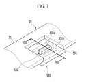
- FIG. 7 is a partial perspective view of a rechargeable battery pack according to a third exemplary embodiment of the present invention.
- FIG. 8 is a cross-sectional view taken along the line VIII-VIII in FIG. 7 .
- a rechargeable battery pack according to the present exemplary embodiment has the same structure as that of the rechargeable battery pack 100 according to a first exemplary embodiment of the present invention excluding a first connection plate 530 and a second connection plate (not shown), hereinafter, detailed description of the same structure will be omitted.
- a first connection plate 530 may include a first connecting portion 531 in which first and second grooves 531a and 531b are formed and a first through-hole 532.
- a second connection plate (not shown) has the same structure as that of the first connection plate 530, hereinafter, detailed description of the second connection plate (not shown) will be omitted.
- the first and second grooves 531a and 531b of the first connecting portion 531 may be formed at both sides of the first through-hole 532 at uniform intervals.
- a plumbic acid 630 may be formed between the first and second grooves 531a and 531b to connect the first connecting portion 531 and the first protruding portion 32 of the first connection tab 30.
- the present exemplary embodiment when the first connecting portion 531 and the first protruding portion 32 are connected by soldering, it is possible to prevent lead molten to form the plumbic acid 630 from flowing down the outside of the first connecting portion 531 due to the first and second grooves 531a and 531b formed in the first connecting portion 531.
- first and second grooves 531a and 531b are formed in the first connection plate 530 according to the present exemplary embodiment.
- a blocking protrusion (not shown) may be formed at the end of the first connecting portion 531 and a plurality of protrusions (not shown) may be formed around the first through-hole 532 formed in the first connecting portion 531.
- FIG. 9 is a partial perspective view of a rechargeable battery pack according to a fourth exemplary embodiment of the present invention.
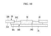
- FIG. 10 is a cross-sectional view taken along the line X-X in FIG. 9 .
- a rechargeable battery pack according to the present exemplary embodiment has the same structure as that of the rechargeable battery pack 100 according to the first exemplary embodiment of the present invention excluding a first connection plate 540 and a second connection plate (not shown), hereinafter, detailed description of the same structure will be omitted.
- the first connection plate 540 may include a first connecting portion 541, a first through-hole 542 and a first fixing portion 543.
- the second connection plate according to the present exemplary embodiment has the same structure as that of the first connecting plate 540, hereinafter, detailed description of the second connection plate (not shown) will be omitted.
- the first fixing portion 543 of the first connection plate 540 may protrude from one side surface of the first connecting portion 541 to be combined with the first combination groove 22 of the protective circuit board 21 by a press-fit technology.
- the side surface of the first fixing portion 543 may be provided to be positioned to face the internal side surface of the first combination groove 22.
- first protruding portion 32 of the first connection tab 30 may be fixed to the first through-hole 542 formed to penetrate the first connecting portion 541 and the first fixing portion 543.
- the first connection plate 540 may be stably combined with the protective circuit board.
- first fixing portion 543 is formed in the first connection plate 540 according to the present exemplary embodiment.
- first and second grooves may be formed, a blocking protrusion (not shown) may be formed at the end of the first connecting portion 541, and a plurality of protrusions (not shown) may be formed around the first through-hole 542.
- FIG. 11 is a partial cross-sectional view of a rechargeable battery pack according to a fifth exemplary embodiment of the present invention.
- a rechargeable battery pack according to the present exemplary embodiment has the same structure as that of the rechargeable battery pack 100 according to the first exemplary embodiment of the present invention excluding a first connection plate 550 and a second connection plate (not shown), hereinafter, detailed description of the same structure will be omitted.
- the first connection plate 550 may include a first connecting portion 551, a first through-hole 552, and a first convex portion 553.
- the second connection plate (not shown) has the same structure as that of the first connection plate 550, hereinafter, detailed description of the second connection plate (not shown) will be omitted.
- the first convex portion 553 may be extended from one end of the first connecting portion 551 in a direction away from the first surface 21a of the protective circuit board 21.
- the first convex portion 553 according to the present exemplary embodiment is formed in a space between the first surface 21a and the unit cell group 10 and the first through-hole 552 is formed in the first convex portion 553 so that the first protruding portion 32 of the first connection tab 30 may be inserted into the first through-hole 552.
- the height H2 of a plumbic acid 650 formed between the first convex portion 553 according to the present exemplary embodiment and the first connection tab 30 may be approximately identical to the thickness t1 of the protective circuit board 21 and the depth D1 of the first convex portion 553.
- the first connection plate 550 may be stably combined with the protective circuit board 21.
- first convex portion 553 is formed in the first connection plate 550 according to the present exemplary embodiment.
- first and second grooves may be formed in the first convex portion 553, a blocking protrusion (not shown) may be formed at the end of the first convex portion 553, and a plurality of protrusions (not shown) may be formed around the first through-hole 552.
- FIG. 12 is a partial cross-sectional view of a rechargeable battery pack according to a sixth exemplary embodiment of the present invention.
- a rechargeable battery pack according to the present exemplary embodiment has the same structure as that of the rechargeable battery pack 100 according to the first exemplary embodiment of the present invention excluding a first connection plate 560 and a second connection plate (not shown), hereinafter, detailed description of the same structure will be omitted.
- the first connection plate 560 may include a first connecting portion 561, a first through-hole 562, a first convex portion 563, and a first combination protrusion 564.
- the second connection plate (not shown) has the same structure as the first connection plate 560, hereinafter, detailed description of the second connection plate (not shown) will be omitted.
- first connection plate 560 has the same structure as the first connection plate 550 according to the fifth exemplary embodiment of the present invention excluding the first combination protrusion 564, hereinafter, detailed description of the same structure will be omitted.
- the first combination protrusion 564 of the first connection plate 560 may be extended from the bottom surface of the first convex portion 563.
- the first combination protrusion 564 may be formed so that the end thereof is positioned between the first surface 21a and the second surface 21b of the protective circuit board 21 from the bottom surface of the first convex portion 563.
- the thickness t2 of the first combination protrusion 564 may be identical to the depth D2 of the first convex portion 563.
- first combination protrusion 564 may include a pair of combination protrusions separated from the first convex portion 563 at uniform intervals.
- first combination protrusion 564 may be fixed to the first combination groove 22 by the press-fit technology or by welding.
- the first connection plate 560 may be stably fixed to the protective circuit board 21.
- first convex portion 563 and the first combination protrusion 564 are formed in the first connection plate 560 according to the present exemplary embodiment.
- first and second grooves may be formed in the first convex portion 553, a blocking protrusion (not shown) may be formed at the end of the first convex portion 553, and a plurality of protrusions (not shown) may be formed around the first through-hole 552.
Landscapes
- Engineering & Computer Science (AREA)
- Chemical & Material Sciences (AREA)
- Chemical Kinetics & Catalysis (AREA)
- Electrochemistry (AREA)
- General Chemical & Material Sciences (AREA)
- Microelectronics & Electronic Packaging (AREA)
- Manufacturing & Machinery (AREA)
- Battery Mounting, Suspending (AREA)
- Connection Of Batteries Or Terminals (AREA)
Abstract

Description
- The described technology relates generally to a rechargeable battery pack. More particularly, the described technology relates generally to a rechargeable battery pack in which the structure of a protective circuit board combined with connection tabs is improved.
- With the technical development of and the increasing demand for mobile devices, demand for rechargeable batteries as energy sources is increasing. A rechargeable battery is used in the form of a single cell and is used in the form of a pack in which a plurality of cells are electrically connected to each other in accordance with the type of a used device.
- In general, a cylindrical rechargeable battery has larger capacity than that of a square type rechargeable battery or a pouch type rechargeable battery. Cylindrical rechargeable batteries may be serially connected, connected in parallel, or connected in a mixed structure to form a rechargeable battery pack in a linear or plate structure.
- The rechargeable battery pack is formed by connecting portion cells to each other by connection tabs to form a cell pack and by electrically connecting the connection tabs of the cell pack to a protective circuit module (PCM). The protective circuit module is formed to protect the cell pack against overcharge, over-discharge, over-current, and short.
- For example, the protective circuit module has through-holes. The ends of the connection tabs are inserted into the through-holes and are electrically connected to the protective circuit module by soldering.
- Therefore, since plumbic acid is formed in a soldering region around the through-holes of the protective circuit module with which the ends of the connection tabs are combined, the volume of the soldering region increases in comparison with the remaining parts of the protective circuit module.
- As a result, since the volume of the protective circuit module is increased by the plumbic acid, it is not possible to design the rechargeable battery pack to be thin.
- The above information disclosed in this Background section is only for enhancement of understanding of the background of the described technology and therefore it may contain information that does not form the prior art that is already known in this country to a person of ordinary skill in the art.
- The described technology has been made in an effort to provide a rechargeable battery pack having advantages of reducing the volume of a protective circuit module.
- Therefore, in order to solve the conventional problem, the object of the present invention is to provide a rechargeable battery pack including a protective circuit board and connection tabs capable of reducing the volume of a protective circuit module.
- A rechargeable battery pack according to an exemplary embodiment includes a plurality of unit cells, connection tabs for electrically connecting the plurality of unit cells to each other, connection plates combined with the connection tabs, and a protective circuit module in which grooves with which the connection plates are combined are formed.
- According to an exemplary embodiment, it is possible to prevent plumbic acid from being formed on the protective circuit board to reduce the volume of the rechargeable battery pack.
- The rechargeable battery pack of the present invention comprises:
- a plurality of unit cells;
- connection tabs for electrically connecting the plurality of unit cells to each other;
- a protective circuit board in which combination grooves are formed;and
- connection plates combined with the connection tabs and disposed on a first surface of the protective circuit board to face with the combination grooves,
- wherein the first surface of the protective circuit board faces with the connection tabs.The combination of connection plates and a protective circuit board with combination grooves proposed with the present invention ensures the formation of a space, deepening or depression which allows to electrically connect the connection tabs and the protective circuit board by soldering without the need to increase the volume of the rechargeable battery pack of the invention by the plumbic acid formed on the protective circuit board.
- Preferably, the rechargeable battery pack of the invention comprises:
- a plurality of unit cells;
- a first and a second connection tab for electrically connecting the plurality of unit cells to each other;
- a first and a second connection plate combined with the first and second connection tabs respectively; and
- a protective circuit board in which a first combination groove and a second combination groove are faced with the first connection plate and the second connection plate, respectively.
- In the rechargeable battery pack of the invention, the connection plates are preferably formed of conductive material to be electrically connected to the protective circuit board.
- Preferably, the connection tabs of the rechargeably battery pack of the invention comprise a body and a protruding portion extending from one side of the body towards the respective connection plate.
- The connection plates of the rechargeable battery pack of the invention may include a connecting portion and a through-hole formed in said connecting portion, wherein a protruding portion of the respective connection tab may be inserted and combined with said through-hole.
- In the rechargeable battery pack of the invention, the protruding portion of the connection tabs (30, 40) is preferably combined with a connection portion of the respective connection plate by soldering.
- Preferably, the protruding portion of the respective connection tab is inserted into the through-hole of said connection plate such that the tip of the protruding portion is positioned not to extend above the plane of a second surface of the protective circuit board opposite to the first surface. Preferably, the tip of the protruding portion is positioned between the first surface and the second surface of the protective circuit board.
- The rechargeable battery pack of the invention can further comprise a plumbic acid which combines the protruding portion of the connecting tab with the connecting portion of the connection plate, wherein the height H1 of the plumbic acid does not extend above the plane of the second surface of the protective circuit board.
- In the rechargeable battery pack of the invention, the connection plates may further comprise a plurality of protrusions on the surface opposed to the first surface of the protective circuit board.
- The connection plates of the rechargeable battery pack of the invention may further comprise a blocking protrusion extending from one end of the connecting portion, wherein the blocking protrusion engages with a combining groove of the protective circuit board.
- Further, the connection plates may comprise at least one groove on the surface opposed to the first surface of the protective circuit board.
- In the rechargeable battery pack of the invention, the connection plates may further comprise a fixing portion which protrudes from one side surface of the connection portion and is formed to combine with the respective combination groove of the protective circuit board, preferably by a press-fit technology. In a preferred embodiment, the side surface of the fixing portion is positioned to face the internal side surface of the respective combination groove of the protective circuit board.
- The connection plates of the rechargeable battery pack of the invention may further comprise a convex portion which extends from one end of the connecting portion in a direction away from the first surface of the protective circuit board. In a preferred embodiment, the connection plates may further comprise a combination protrusion extending from a bottom surface of the convex portion and being formed so that the end of the combination protrusion is positioned between the first surface and the second surface of the protective circuit board.
-
-
FIG. 1 is a perspective view schematically illustrating a rechargeable battery pack according to a first exemplary embodiment of the present invention. -
FIG. 2 is an exploded perspective view of the rechargeable battery pack ofFIG. 1 . -
FIG. 3 is a partial cross-sectional view of the rechargeable battery pack taken along the line III-III inFIG. 1 . -
FIG. 4 is a perspective view of a connection plate according to an exemplary variation of the first exemplary embodiment of the present invention. -
FIG. 5 is a partial perspective view of a rechargeable battery pack according to a second exemplary embodiment of the present invention. -
FIG. 6 is a cross-sectional view taken along the line VI-VI inFIG. 5 . -
FIG. 7 is a partial perspective view of a rechargeable battery pack according to a third exemplary embodiment of the present invention. -
FIG. 8 is a cross-sectional view taken along the line VIII-VIII inFIG. 7 . -
FIG. 9 is a partial perspective view of a rechargeable battery pack according to a fourth exemplary embodiment of the present invention. -
FIG. 10 is a cross-sectional view taken along the line X-X inFIG. 9 . -
FIG. 11 is a partial cross-sectional view of a rechargeable battery pack according to a fifth exemplary embodiment of the present invention. -
FIG. 12 is a partial cross-sectional view of a rechargeable battery pack according to a sixth exemplary embodiment of the present invention. - Hereinafter, exemplary embodiments of the present invention will be described in detail with reference to the accompanying drawings so that a person of ordinary skill in the art may easily perform the present invention. As those skilled in the art would realize, the described embodiments may be modified in various different ways, all without departing from the spirit or scope of the present invention.
- The drawings and description are to be regarded as illustrative in nature and not restrictive. Like reference numerals designate like elements throughout the specification.
-
FIG. 1 is a perspective view schematically illustrating a rechargeable battery pack according to a first exemplary embodiment of the present invention.FIG. 2 is an exploded perspective view of the rechargeable battery pack ofFIG. 1 . - Referring to
FIGs. 1 and2 , a rechargeable battery pack 100 according to the present exemplary embodiment includes aunit cell group 10 including first tofourth unit cells protective circuit module 20 electrically connected to theunit cell group 10, afirst connection tab 30, asecond connection tab 40, afirst connection plate 50, and asecond connection plate 70. - In the
unit cell group 10 according to the present exemplary embodiment, thefirst unit cell 11 and thesecond unit cell 12 may be serially connected, thethird unit cell 13 and thefourth unit cell 14 may be serially connected, and the serially connected first andsecond unit cells fourth unit cells - More concretely, the
first connection tab 30 is combined withpositive terminals fourth unit cells second connection tab 40 is combined withnegative terminals third unit cells second unit cells fourth unit cells - The
unit cell group 10 according to the present exemplary embodiment is not limited to including the four first tofourth unit cells - The first to
fourth unit cells - Protective circuit elements (not shown) may be mounted in the
protective circuit module 20 according to the present exemplary embodiment so that the first tofourth unit cells - More concretely, the
protective circuit module 20 according to the present exemplary embodiment may include aprotective circuit board 21. - Here, in the
protective circuit board 21 according to the present exemplary embodiment, afirst combination groove 22 and asecond combination groove 23 are formed so that thefirst connection plate 50 and thesecond connection plate 70 may be combined with thefirst combination groove 22 and thesecond combination groove 23, respectively. - Here, the first and
second connection plates protective circuit board 21. - In addition, the first connection tab according to the present exemplary embodiment may include a
first body 31 and a first protrudingportion 32 extended from one side of thefirst body 31 and thesecond connection tab 40 may include asecond body 41 and a second protrudingportion 42 extended from one side of thesecond body 41. - In addition, the
first connection plate 50 according to the present exemplary embodiment may include a first connectingportion 51 and a first through-hole 52 formed to penetrate the first connectingportion 51 and thesecond connection plate 70 may include a second connectingportion 71 and a second through-hole 72 formed to penetrate the second connectingportion 71. - According to the present exemplary embodiment, the first and
second bodies second connection tabs negative electrodes third unit cells - In addition, the first and second protruding
portions second connection tabs holes second connection plates - Therefore, according to the present exemplary embodiment, the
unit cell group 10 and theprotective circuit module 20 may be electrically connected through the first andsecond connection tabs - At this time, the first and second protruding
portions second connection tabs portions second connection plates -
FIG. 3 is a partial cross-sectional view of the rechargeable battery pack taken along the line III-III inFIG. 1 . - Referring to
FIG. 3 , the first protrudingportion 32 of thefirst connection tab 30 according to the present exemplary embodiment may be inserted into the first through-hole 52 formed in the first connectingportion 51 of thefirst connection plate 50. - Since the
second connection tab 40 and thesecond connection plate 70 according to the present exemplary embodiment have the same structure and combination relationship as those of thefirst connection tab 30 and thefirst connection plate 50, hereinafter, detailed description of thesecond connection tab 40 and thesecond connection plate 70 will be omitted. - Here, the first connecting
portion 51 of thefirst connection plate 50 may be combined with afirst surface 21a of theprotective circuit board 21 and the first protrudingportion 32 is preferably inserted into the first through-hole 52 so that an end or tip 321 thereof is positioned on the same plane as asecond surface 21b of theprotective circuit board 21 or, in other words, is positioned not to extend above the plane of thesecond surface 21b of theprotective circuit board 21. - In addition, the first protruding
portion 32 of thefirst connection tab 30 and the first connectingportion 51 of thefirst connection plate 50 may be combined by soldering. - Therefore, according to the present exemplary embodiment, a
plumbic acid 60 that combines the first protrudingportion 32 with the first connectingportion 51 may be formed. - Here, since the
end 321 of the first protrudingportion 32 is positioned on the same plane as thesecond surface 21b of theprotective circuit board 21 or below, theplumbic acid 60 according to the present exemplary embodiment may be formed between thesecond surface 21b of theprotective circuit board 21 and the first connectingportion 51. - For example, the height H1 of the
plumbic acid 60 according to the present exemplary embodiment may be identical to or smaller than a thickness t1 between thefirst surface 21a and thesecond surface 21b of theprotective circuit board 21. - Therefore, according to the present exemplary embodiment, when the
unit cell group 10 and theprotective circuit module 20 are connected by soldering, it is possible to prevent the volume of the rechargeable battery pack from being increased by theplumbic acid 60 formed on theprotective circuit board 21. -
FIG. 4 is a perspective view of a connection plate according to an exemplary variation of the first exemplary embodiment of the present invention. - Since the rechargeable battery pack according to the present exemplary embodiment has the same structure as that of the rechargeable battery pack 100 according to the first exemplary embodiment of the present invention excluding a
first connection plate 510 and a second connection plate (not shown), hereinafter, detailed description of the same structure will be omitted. - The
first connection plate 510 according to the present exemplary embodiment may include a first connectingportion 511 and a first through-hole 512 formed to penetrate the first connectingportion 511. - Here, since the
first connection plate 510 and the second connection plate (not shown) according to the present exemplary embodiment have the same structure, hereinafter, detailed description of the second connection plate (not shown) will be omitted. - A plurality of
protrusions 513 may be formed in the first connectingportion 511 of thefirst connection plate 510 according to the present exemplary embodiment. - Therefore, according to the present exemplary embodiment, since the surface area of the first connecting
portion 511 of thefirst connection plate 510 is increased by the plurality ofprotrusions 513, a plumbic acid (not shown) may be stably formed between the first connectingportion 511 and the first protrudingportion 32. -
FIG. 5 is a partial perspective view of a rechargeable battery pack according to a second exemplary embodiment of the present invention.FIG. 6 is a cross-sectional view taken along the line VI-VI inFIG. 5 . - Since a rechargeable battery pack according to the present exemplary embodiment has the same structure as that of the rechargeable battery pack 100 according to the first exemplary embodiment of the present invention excluding a
first connection plate 520 and a second connection plate (not shown), hereinafter, detailed description of the same structure will be omitted. - Referring to
FIGs. 5 and6 , thefirst connection plate 520 according to the present exemplary embodiment may include a first connectingportion 521, a first through-hole 522, and afirst blocking protrusion 523. - Here, since the second connection plate (not shown) according to the present exemplary embodiment has the same structure as that of the
first connection plate 520, hereinafter, detailed description of the second connection plate (not shown) will be omitted. - The
first blocking protrusion 523 of thefirst connection plate 520 according to the present exemplary embodiment may be extended from one end of the first connectingportion 521. - For example, the
first blocking protrusion 523 according to the present exemplary embodiment may be extended from one end of the first connectingportion 521 to approximately run parallel with the direction of the thickness t1 of theprotective circuit board 21. - Therefore, a
plumbic acid 620 according to the present exemplary embodiment may be formed between thefirst blocking protrusion 523 and theprotective circuit board 21. - That is, according to the present exemplary embodiment, when the first connecting
portion 521 and the first protrudingportion 32 are connected by soldering, it is possible to prevent lead molten to form theplumbic acid 620 from flowing down the outside of the first connectingportion 521 due to thefirst blocking protrusion 523 formed at one end of the first connectingportion 521. - According to the present exemplary embodiment, not only the
first blocking protrusion 523 is formed in thefirst connection plate 520. - Therefore, together with the
first blocking protrusion 523 formed at the end of the first connectingportion 521, a plurality of protrusions (not shown) may be formed around the first through-hole 522. -
FIG. 7 is a partial perspective view of a rechargeable battery pack according to a third exemplary embodiment of the present invention.FIG. 8 is a cross-sectional view taken along the line VIII-VIII inFIG. 7 . - Since a rechargeable battery pack according to the present exemplary embodiment has the same structure as that of the rechargeable battery pack 100 according to a first exemplary embodiment of the present invention excluding a
first connection plate 530 and a second connection plate (not shown), hereinafter, detailed description of the same structure will be omitted. - Referring to
FIGs. 7 and8 , afirst connection plate 530 according to the present exemplary embodiment may include a first connectingportion 531 in which first andsecond grooves hole 532. - Here, since a second connection plate (not shown) according to the present exemplary embodiment has the same structure as that of the
first connection plate 530, hereinafter, detailed description of the second connection plate (not shown) will be omitted. - The first and
second grooves portion 531 according to the present exemplary embodiment may be formed at both sides of the first through-hole 532 at uniform intervals. - In addition, a
plumbic acid 630 according to the present exemplary embodiment may be formed between the first andsecond grooves portion 531 and the first protrudingportion 32 of thefirst connection tab 30. - Therefore, according to the present exemplary embodiment, when the first connecting
portion 531 and the first protrudingportion 32 are connected by soldering, it is possible to prevent lead molten to form theplumbic acid 630 from flowing down the outside of the first connectingportion 531 due to the first andsecond grooves portion 531. - Not only the first and
second grooves first connection plate 530 according to the present exemplary embodiment. - Therefore, in the
first connection plate 530, together with the first andsecond grooves portion 531 and a plurality of protrusions (not shown) may be formed around the first through-hole 532 formed in the first connectingportion 531. -
FIG. 9 is a partial perspective view of a rechargeable battery pack according to a fourth exemplary embodiment of the present invention.FIG. 10 is a cross-sectional view taken along the line X-X inFIG. 9 . - Since a rechargeable battery pack according to the present exemplary embodiment has the same structure as that of the rechargeable battery pack 100 according to the first exemplary embodiment of the present invention excluding a
first connection plate 540 and a second connection plate (not shown), hereinafter, detailed description of the same structure will be omitted. - Referring to
FIGs. 9 and10 , thefirst connection plate 540 according to the present exemplary embodiment may include a first connectingportion 541, a first through-hole 542 and afirst fixing portion 543. - Here, since the second connection plate according to the present exemplary embodiment has the same structure as that of the first connecting
plate 540, hereinafter, detailed description of the second connection plate (not shown) will be omitted. - The
first fixing portion 543 of thefirst connection plate 540 according to the present exemplary embodiment may protrude from one side surface of the first connectingportion 541 to be combined with thefirst combination groove 22 of theprotective circuit board 21 by a press-fit technology. - More concretely, the side surface of the
first fixing portion 543 according to the present exemplary embodiment may be provided to be positioned to face the internal side surface of thefirst combination groove 22. - In addition, the first protruding
portion 32 of thefirst connection tab 30 may be fixed to the first through-hole 542 formed to penetrate the first connectingportion 541 and thefirst fixing portion 543. - Therefore, according to the present exemplary embodiment, since the first connecting
portion 541 is combined with thefirst surface 21a of theprotective circuit board 21 by welding and thefirst fixing portion 543 is fixed to thefirst combination groove 22 by the press-fit technology, thefirst connection plate 540 may be stably combined with the protective circuit board. - Not only the
first fixing portion 543 is formed in thefirst connection plate 540 according to the present exemplary embodiment. - Therefore, in the
first connection plate 540, together with thefirst fixing portion 543, first and second grooves (not shown) may be formed, a blocking protrusion (not shown) may be formed at the end of the first connectingportion 541, and a plurality of protrusions (not shown) may be formed around the first through-hole 542. -
FIG. 11 is a partial cross-sectional view of a rechargeable battery pack according to a fifth exemplary embodiment of the present invention. - Since a rechargeable battery pack according to the present exemplary embodiment has the same structure as that of the rechargeable battery pack 100 according to the first exemplary embodiment of the present invention excluding a
first connection plate 550 and a second connection plate (not shown), hereinafter, detailed description of the same structure will be omitted. - Referring to
FIG. 11 , thefirst connection plate 550 according to the present exemplary embodiment may include a first connectingportion 551, a first through-hole 552, and a firstconvex portion 553. - Here, since the second connection plate (not shown) according to the present exemplary embodiment has the same structure as that of the
first connection plate 550, hereinafter, detailed description of the second connection plate (not shown) will be omitted. - The first
convex portion 553 according to the present exemplary embodiment may be extended from one end of the first connectingportion 551 in a direction away from thefirst surface 21a of theprotective circuit board 21. - More concretely, the first
convex portion 553 according to the present exemplary embodiment is formed in a space between thefirst surface 21a and theunit cell group 10 and the first through-hole 552 is formed in the firstconvex portion 553 so that the first protrudingportion 32 of thefirst connection tab 30 may be inserted into the first through-hole 552. - Therefore, the height H2 of a
plumbic acid 650 formed between the firstconvex portion 553 according to the present exemplary embodiment and thefirst connection tab 30 may be approximately identical to the thickness t1 of theprotective circuit board 21 and the depth D1 of the firstconvex portion 553. - As a result, according to the present exemplary embodiment, since the height H2 of the
plumbic acid 650 increases by the depth D1 of the firstconvex portion 553, thefirst connection plate 550 may be stably combined with theprotective circuit board 21. - Not only the first
convex portion 553 is formed in thefirst connection plate 550 according to the present exemplary embodiment. - Therefore, according to the present exemplary embodiment, together with the first
convex portion 553 formed in thefirst connection plate 550, first and second grooves (not shown) may be formed in the firstconvex portion 553, a blocking protrusion (not shown) may be formed at the end of the firstconvex portion 553, and a plurality of protrusions (not shown) may be formed around the first through-hole 552. -
FIG. 12 is a partial cross-sectional view of a rechargeable battery pack according to a sixth exemplary embodiment of the present invention. - Since a rechargeable battery pack according to the present exemplary embodiment has the same structure as that of the rechargeable battery pack 100 according to the first exemplary embodiment of the present invention excluding a
first connection plate 560 and a second connection plate (not shown), hereinafter, detailed description of the same structure will be omitted. - Referring to
FIG. 12 , thefirst connection plate 560 according to the present exemplary embodiment may include a first connectingportion 561, a first through-hole 562, a firstconvex portion 563, and afirst combination protrusion 564. - Here, since the second connection plate (not shown) according to the present exemplary embodiment has the same structure as the
first connection plate 560, hereinafter, detailed description of the second connection plate (not shown) will be omitted. - In addition, since the
first connection plate 560 according to the present exemplary embodiment has the same structure as thefirst connection plate 550 according to the fifth exemplary embodiment of the present invention excluding thefirst combination protrusion 564, hereinafter, detailed description of the same structure will be omitted. - The
first combination protrusion 564 of thefirst connection plate 560 according to the present exemplary embodiment may be extended from the bottom surface of the firstconvex portion 563. - More concretely, the
first combination protrusion 564 according to the present exemplary embodiment may be formed so that the end thereof is positioned between thefirst surface 21a and thesecond surface 21b of theprotective circuit board 21 from the bottom surface of the firstconvex portion 563. - Therefore, the thickness t2 of the
first combination protrusion 564 according to the present exemplary embodiment may be identical to the depth D2 of the firstconvex portion 563. - In addition, the
first combination protrusion 564 according to the present exemplary embodiment may include a pair of combination protrusions separated from the firstconvex portion 563 at uniform intervals. - In addition, the
first combination protrusion 564 according to the present exemplary embodiment may be fixed to thefirst combination groove 22 by the press-fit technology or by welding. - As a result, according to the present exemplary embodiment, since the
first connection portion 561 is combined with thefirst surface 21a of theprotective circuit board 21 and thefirst combination protrusion 564 is combined with thefirst combination groove 22, thefirst connection plate 560 may be stably fixed to theprotective circuit board 21. - Not only the first
convex portion 563 and thefirst combination protrusion 564 are formed in thefirst connection plate 560 according to the present exemplary embodiment. - Therefore, according to the present exemplary embodiment, together with the first
convex portion 563 formed in thefirst connection plate 560, first and second grooves (not shown) may be formed in the firstconvex portion 553, a blocking protrusion (not shown) may be formed at the end of the firstconvex portion 553, and a plurality of protrusions (not shown) may be formed around the first through-hole 552.
Claims (15)
- Rechargeable battery pack, comprising
a plurality of unit cells (11, 12, 13, 14);
connection tabs (30, 40) for electrically connecting the plurality of unit cells (11, 12, 13, 14) to each other;
a protective circuit board (21) in which combination grooves (22, 23) are formed,
and
connection plates (50, 70) combined with the connection tabs (30, 40) and disposed on a first surface (21a) of the protective circuit board (21) to face with the combination grooves (22, 23),
wherein the first surface (21a) of the protective circuit board (21) faces with the connection tabs (30, 40). - Rechargeable battery pack of claim 1, comprising
a plurality of unit cells (11, 12, 13, 14);
a first (30) and a second (40) connection tab for electrically connecting the plurality of unit cells (11, 12, 13, 14) to each other;
a first (50) and a second (70) connection plate combined with the first (30) and second (40) connection tabs respectively; and
a protective circuit board (21) in which a first combination groove (22) and a second combination groove (23) are faced with the first connection plate (50) and the second connection plate (70), respectively. - Rechargeable battery pack of one of the preceding claims, wherein the connection plates (50, 70) are formed of conductive material to be electrically connected to the protective circuit board (21).
- Rechargeable battery pack of one of the preceding claims, wherein each connection tab (30, 40) comprises a body (31, 41) and a protruding portion (32, 42) extending from one side of the body (31, 41) towards the respective connection plate (50, 70).
- Rechargeable battery pack of one of the preceding claims, wherein each connection plate (50, 70) includes a connecting portion (51, 71) and a through-hole (52, 72) formed in said connecting portion (51, 71), and wherein a protruding portion (32, 42) of the respective connection tab (30, 40) is inserted and combined with said through-hole (52, 72).
- Rechargeable battery pack of one of claims 4 or 5, wherein the protruding portion (32, 42) of each connection tab (30, 40) is combined with a connection portion (51, 71) of a respective connection plate (50, 70) by soldering.
- Rechargeable battery pack of one of claims 4 to 6, wherein the protruding portion (32, 42) of the respective connection tab (30, 40) is inserted into the through-hole (52, 72) of said connection plate (50, 70) such that the tip (321) of the protruding portion (32, 42) is positioned not to extend above the plane of a second surface (21b) of the protective circuit board (21) opposite to the first surface (21a).
- Rechargeable battery pack of claim 7, further comprising a plumbic acid (60) which combines the protruding portion (32, 42) of the connecting tab (30, 40) with the connecting portion (51, 71) of the connection plate (50, 70), wherein the height H1 of the plumbic acid (60) does not extend above the plane of the second surface (21b) of the protective circuit board (21).
- Rechargeable battery pack of one of the preceding claims, wherein the connection plates further comprise a plurality of protrusions (513) on the surface opposed to the first surface (21a) of the protective circuit board (21).
- Rechargeable battery pack of one of claims 5 to 9, wherein the connection plates comprise a blocking protrusion (522) extending from one end of the connecting portion, wherein the blocking protrusion (522) engages with a combining groove of the protective circuit board (21).
- Rechargeable battery pack of one of the preceding claims, wherein the connection plates comprise at least one groove (531a, 531b) on the surface opposed to the first surface (21a) of the protective circuit board (21).
- Rechargeable battery pack of one claims 5 to 11, wherein the connection plates further comprise a fixing portion (543) which protrudes from one side surface of the connection portion and is formed to combine with the respective combination groove of the protective circuit board (21) by a press-fit technology.
- Rechargeable battery pack of claim 12, wherein the side surface of the fixing portion (543) is positioned to face the internal side surface of the respective combination groove of the protective circuit board (21).
- Rechargeable battery pack of one of claims 5 to 13, wherein the connection plates further comprise a convex portion (553, 563) which extends from one end of the connecting portion in a direction away from the first surface of the protective circuit board (21).
- Rechargeable battery pack of claim 14, wherein the connection plates further comprise a combination protrusion (564) extending from a bottom surface of the convex portion (553, 563) and being formed so that the end of the combination protrusion (564) is positioned between the first surface (21a) and the second surface (21b) of the protective circuit board (21).
Applications Claiming Priority (2)
| Application Number | Priority Date | Filing Date | Title |
|---|---|---|---|
| US201361755318P | 2013-01-22 | 2013-01-22 | |
| US14/019,486 US20140205864A1 (en) | 2013-01-22 | 2013-09-05 | Rechargeable battery pack |
Publications (2)
| Publication Number | Publication Date |
|---|---|
| EP2757613A1 true EP2757613A1 (en) | 2014-07-23 |
| EP2757613B1 EP2757613B1 (en) | 2015-11-18 |
Family
ID=49161999
Family Applications (1)
| Application Number | Title | Priority Date | Filing Date |
|---|---|---|---|
| EP13183848.4A Not-in-force EP2757613B1 (en) | 2013-01-22 | 2013-09-11 | Rechargeable battery pack |
Country Status (5)
| Country | Link |
|---|---|
| US (1) | US20140205864A1 (en) |
| EP (1) | EP2757613B1 (en) |
| JP (1) | JP2014143180A (en) |
| KR (1) | KR101537001B1 (en) |
| CN (1) | CN103943900A (en) |
Cited By (1)
| Publication number | Priority date | Publication date | Assignee | Title |
|---|---|---|---|---|
| CN110651380A (en) * | 2017-05-18 | 2020-01-03 | 日本光电工业株式会社 | Battery holder and electronic device |
Families Citing this family (4)
| Publication number | Priority date | Publication date | Assignee | Title |
|---|---|---|---|---|
| KR200481954Y1 (en) * | 2014-12-19 | 2016-12-01 | 세방전지(주) | Screw bushing for car battery |
| KR102167430B1 (en) * | 2016-10-24 | 2020-10-20 | 주식회사 엘지화학 | Battery pack |
| KR102249488B1 (en) * | 2018-03-12 | 2021-05-06 | 주식회사 엘지화학 | An energy storage device with a hook structure and an energy storage system comprising the same |
| KR102813678B1 (en) * | 2022-09-19 | 2025-05-29 | 주식회사 경신전선 | Fixing module of circuit-board and terminal |
Citations (4)
| Publication number | Priority date | Publication date | Assignee | Title |
|---|---|---|---|---|
| JPH0887992A (en) * | 1994-09-16 | 1996-04-02 | Philips Japan Ltd | Battery mounting clip |
| US20060032667A1 (en) * | 2003-01-23 | 2006-02-16 | Sony Corporation | Lead terminal and power supply device |
| EP2187465A1 (en) * | 2008-11-17 | 2010-05-19 | Kabushi Kaisha Toshiba | Secondary battery pack |
| EP2337116A2 (en) * | 2008-10-14 | 2011-06-22 | LG Chem, Ltd. | Electrode terminal connection member for producing a core pack |
Family Cites Families (9)
| Publication number | Priority date | Publication date | Assignee | Title |
|---|---|---|---|---|
| JP4027141B2 (en) * | 2002-04-08 | 2007-12-26 | 三洋ジーエスソフトエナジー株式会社 | battery |
| JP2006346731A (en) * | 2005-06-20 | 2006-12-28 | Nec Tokin Corp | Substrate and tool for preventing solder scattering |
| KR100686800B1 (en) * | 2005-07-26 | 2007-02-26 | 삼성에스디아이 주식회사 | Secondary battery |
| KR100965683B1 (en) * | 2008-03-31 | 2010-06-24 | 삼성에스디아이 주식회사 | Battery pack |
| US20100055560A1 (en) * | 2008-08-29 | 2010-03-04 | Youngcheol Jang | Secondary battery |
| KR101147236B1 (en) * | 2010-08-31 | 2012-05-18 | 삼성에스디아이 주식회사 | Rechargeable battery pack |
| KR101209981B1 (en) * | 2010-11-19 | 2012-12-07 | 삼성에스디아이 주식회사 | Printed circuit board and battery pack using the same |
| WO2013076911A1 (en) * | 2011-11-25 | 2013-05-30 | パナソニック株式会社 | Cell pack |
| US8586217B2 (en) * | 2011-12-22 | 2013-11-19 | Samsung Sdi Co., Ltd. | Protective circuit module |
-
2013
- 2013-09-05 US US14/019,486 patent/US20140205864A1/en not_active Abandoned
- 2013-09-11 EP EP13183848.4A patent/EP2757613B1/en not_active Not-in-force
- 2013-10-23 KR KR1020130126556A patent/KR101537001B1/en not_active Expired - Fee Related
- 2013-12-03 JP JP2013250133A patent/JP2014143180A/en active Pending
-
2014
- 2014-01-17 CN CN201410022572.XA patent/CN103943900A/en active Pending
Patent Citations (4)
| Publication number | Priority date | Publication date | Assignee | Title |
|---|---|---|---|---|
| JPH0887992A (en) * | 1994-09-16 | 1996-04-02 | Philips Japan Ltd | Battery mounting clip |
| US20060032667A1 (en) * | 2003-01-23 | 2006-02-16 | Sony Corporation | Lead terminal and power supply device |
| EP2337116A2 (en) * | 2008-10-14 | 2011-06-22 | LG Chem, Ltd. | Electrode terminal connection member for producing a core pack |
| EP2187465A1 (en) * | 2008-11-17 | 2010-05-19 | Kabushi Kaisha Toshiba | Secondary battery pack |
Cited By (1)
| Publication number | Priority date | Publication date | Assignee | Title |
|---|---|---|---|---|
| CN110651380A (en) * | 2017-05-18 | 2020-01-03 | 日本光电工业株式会社 | Battery holder and electronic device |
Also Published As
| Publication number | Publication date |
|---|---|
| CN103943900A (en) | 2014-07-23 |
| KR20140094425A (en) | 2014-07-30 |
| EP2757613B1 (en) | 2015-11-18 |
| US20140205864A1 (en) | 2014-07-24 |
| JP2014143180A (en) | 2014-08-07 |
| KR101537001B1 (en) | 2015-07-15 |
Similar Documents
| Publication | Publication Date | Title |
|---|---|---|
| US11843128B2 (en) | Cell module | |
| KR102444124B1 (en) | Battery module and battery pack comprising same | |
| KR100880389B1 (en) | Manufacturing Method of Secondary Battery Module | |
| US10547037B2 (en) | Battery module, and battery pack and vehicle comprising the same | |
| CN111033794B (en) | Battery module | |
| US11456500B2 (en) | Battery module, battery pack including battery module, and vehicle including battery pack | |
| EP3736883A1 (en) | Battery module including secondary battery and bus bar | |
| KR102317503B1 (en) | Battery Pack | |
| US20100203363A1 (en) | Connector assembly and battery pack having the same | |
| US20140199573A1 (en) | Battery pack | |
| KR101984314B1 (en) | Secondary battery | |
| EP3540814A1 (en) | End plate, housing, and battery module | |
| EP2757613B1 (en) | Rechargeable battery pack | |
| KR101897822B1 (en) | Battery pack | |
| US10270080B2 (en) | Battery pack | |
| KR102577098B1 (en) | Bettery module | |
| KR20220085598A (en) | Battery module | |
| KR102097083B1 (en) | Battery pack case and battery pack including the battery pack case, car | |
| CN105990601B (en) | Battery | |
| KR102598670B1 (en) | Battery module | |
| KR102756464B1 (en) | Battery module | |
| KR102073191B1 (en) | Battery pack | |
| US20150228960A1 (en) | Battery pack | |
| KR101039517B1 (en) | Battery cell connection member | |
| CN110622340A (en) | Battery module and method for manufacturing battery module |
Legal Events
| Date | Code | Title | Description |
|---|---|---|---|
| PUAI | Public reference made under article 153(3) epc to a published international application that has entered the european phase |
Free format text: ORIGINAL CODE: 0009012 |
|
| 17P | Request for examination filed |
Effective date: 20130911 |
|
| AK | Designated contracting states |
Kind code of ref document: A1 Designated state(s): AL AT BE BG CH CY CZ DE DK EE ES FI FR GB GR HR HU IE IS IT LI LT LU LV MC MK MT NL NO PL PT RO RS SE SI SK SM TR |
|
| AX | Request for extension of the european patent |
Extension state: BA ME |
|
| R17P | Request for examination filed (corrected) |
Effective date: 20150108 |
|
| RBV | Designated contracting states (corrected) |
Designated state(s): AL AT BE BG CH CY CZ DE DK EE ES FI FR GB GR HR HU IE IS IT LI LT LU LV MC MK MT NL NO PL PT RO RS SE SI SK SM TR |
|
| GRAP | Despatch of communication of intention to grant a patent |
Free format text: ORIGINAL CODE: EPIDOSNIGR1 |
|
| RIC1 | Information provided on ipc code assigned before grant |
Ipc: H01M 2/10 20060101ALN20150605BHEP Ipc: H01M 2/34 20060101ALI20150605BHEP Ipc: H05K 3/34 20060101ALI20150605BHEP Ipc: H01M 10/42 20060101ALI20150605BHEP Ipc: H05K 3/40 20060101ALI20150605BHEP Ipc: H01M 2/20 20060101AFI20150605BHEP Ipc: H05K 1/00 20060101ALI20150605BHEP |
|
| INTG | Intention to grant announced |
Effective date: 20150623 |
|
| GRAS | Grant fee paid |
Free format text: ORIGINAL CODE: EPIDOSNIGR3 |
|
| GRAA | (expected) grant |
Free format text: ORIGINAL CODE: 0009210 |
|
| AK | Designated contracting states |
Kind code of ref document: B1 Designated state(s): AL AT BE BG CH CY CZ DE DK EE ES FI FR GB GR HR HU IE IS IT LI LT LU LV MC MK MT NL NO PL PT RO RS SE SI SK SM TR |
|
| REG | Reference to a national code |
Ref country code: GB Ref legal event code: FG4D |
|
| REG | Reference to a national code |
Ref country code: CH Ref legal event code: EP |
|
| REG | Reference to a national code |
Ref country code: AT Ref legal event code: REF Ref document number: 761947 Country of ref document: AT Kind code of ref document: T Effective date: 20151215 |
|
| REG | Reference to a national code |
Ref country code: IE Ref legal event code: FG4D |
|
| REG | Reference to a national code |
Ref country code: DE Ref legal event code: R096 Ref document number: 602013003854 Country of ref document: DE |
|
| REG | Reference to a national code |
Ref country code: NL Ref legal event code: MP Effective date: 20160218 |
|
| REG | Reference to a national code |
Ref country code: LT Ref legal event code: MG4D |
|
| REG | Reference to a national code |
Ref country code: AT Ref legal event code: MK05 Ref document number: 761947 Country of ref document: AT Kind code of ref document: T Effective date: 20151118 |
|
| PG25 | Lapsed in a contracting state [announced via postgrant information from national office to epo] |
Ref country code: NO Free format text: LAPSE BECAUSE OF FAILURE TO SUBMIT A TRANSLATION OF THE DESCRIPTION OR TO PAY THE FEE WITHIN THE PRESCRIBED TIME-LIMIT Effective date: 20160218 Ref country code: HR Free format text: LAPSE BECAUSE OF FAILURE TO SUBMIT A TRANSLATION OF THE DESCRIPTION OR TO PAY THE FEE WITHIN THE PRESCRIBED TIME-LIMIT Effective date: 20151118 Ref country code: NL Free format text: LAPSE BECAUSE OF FAILURE TO SUBMIT A TRANSLATION OF THE DESCRIPTION OR TO PAY THE FEE WITHIN THE PRESCRIBED TIME-LIMIT Effective date: 20151118 Ref country code: ES Free format text: LAPSE BECAUSE OF FAILURE TO SUBMIT A TRANSLATION OF THE DESCRIPTION OR TO PAY THE FEE WITHIN THE PRESCRIBED TIME-LIMIT Effective date: 20151118 Ref country code: IT Free format text: LAPSE BECAUSE OF FAILURE TO SUBMIT A TRANSLATION OF THE DESCRIPTION OR TO PAY THE FEE WITHIN THE PRESCRIBED TIME-LIMIT Effective date: 20151118 Ref country code: LT Free format text: LAPSE BECAUSE OF FAILURE TO SUBMIT A TRANSLATION OF THE DESCRIPTION OR TO PAY THE FEE WITHIN THE PRESCRIBED TIME-LIMIT Effective date: 20151118 Ref country code: IS Free format text: LAPSE BECAUSE OF FAILURE TO SUBMIT A TRANSLATION OF THE DESCRIPTION OR TO PAY THE FEE WITHIN THE PRESCRIBED TIME-LIMIT Effective date: 20160318 |
|
| PG25 | Lapsed in a contracting state [announced via postgrant information from national office to epo] |
Ref country code: RS Free format text: LAPSE BECAUSE OF FAILURE TO SUBMIT A TRANSLATION OF THE DESCRIPTION OR TO PAY THE FEE WITHIN THE PRESCRIBED TIME-LIMIT Effective date: 20151118 Ref country code: SE Free format text: LAPSE BECAUSE OF FAILURE TO SUBMIT A TRANSLATION OF THE DESCRIPTION OR TO PAY THE FEE WITHIN THE PRESCRIBED TIME-LIMIT Effective date: 20151118 Ref country code: PT Free format text: LAPSE BECAUSE OF FAILURE TO SUBMIT A TRANSLATION OF THE DESCRIPTION OR TO PAY THE FEE WITHIN THE PRESCRIBED TIME-LIMIT Effective date: 20160318 Ref country code: GR Free format text: LAPSE BECAUSE OF FAILURE TO SUBMIT A TRANSLATION OF THE DESCRIPTION OR TO PAY THE FEE WITHIN THE PRESCRIBED TIME-LIMIT Effective date: 20160219 Ref country code: AT Free format text: LAPSE BECAUSE OF FAILURE TO SUBMIT A TRANSLATION OF THE DESCRIPTION OR TO PAY THE FEE WITHIN THE PRESCRIBED TIME-LIMIT Effective date: 20151118 Ref country code: LV Free format text: LAPSE BECAUSE OF FAILURE TO SUBMIT A TRANSLATION OF THE DESCRIPTION OR TO PAY THE FEE WITHIN THE PRESCRIBED TIME-LIMIT Effective date: 20151118 Ref country code: FI Free format text: LAPSE BECAUSE OF FAILURE TO SUBMIT A TRANSLATION OF THE DESCRIPTION OR TO PAY THE FEE WITHIN THE PRESCRIBED TIME-LIMIT Effective date: 20151118 Ref country code: PL Free format text: LAPSE BECAUSE OF FAILURE TO SUBMIT A TRANSLATION OF THE DESCRIPTION OR TO PAY THE FEE WITHIN THE PRESCRIBED TIME-LIMIT Effective date: 20151118 |
|
| PG25 | Lapsed in a contracting state [announced via postgrant information from national office to epo] |
Ref country code: CZ Free format text: LAPSE BECAUSE OF FAILURE TO SUBMIT A TRANSLATION OF THE DESCRIPTION OR TO PAY THE FEE WITHIN THE PRESCRIBED TIME-LIMIT Effective date: 20151118 |
|
| REG | Reference to a national code |
Ref country code: DE Ref legal event code: R097 Ref document number: 602013003854 Country of ref document: DE |
|
| PG25 | Lapsed in a contracting state [announced via postgrant information from national office to epo] |
Ref country code: SK Free format text: LAPSE BECAUSE OF FAILURE TO SUBMIT A TRANSLATION OF THE DESCRIPTION OR TO PAY THE FEE WITHIN THE PRESCRIBED TIME-LIMIT Effective date: 20151118 Ref country code: RO Free format text: LAPSE BECAUSE OF FAILURE TO SUBMIT A TRANSLATION OF THE DESCRIPTION OR TO PAY THE FEE WITHIN THE PRESCRIBED TIME-LIMIT Effective date: 20151118 Ref country code: EE Free format text: LAPSE BECAUSE OF FAILURE TO SUBMIT A TRANSLATION OF THE DESCRIPTION OR TO PAY THE FEE WITHIN THE PRESCRIBED TIME-LIMIT Effective date: 20151118 Ref country code: DK Free format text: LAPSE BECAUSE OF FAILURE TO SUBMIT A TRANSLATION OF THE DESCRIPTION OR TO PAY THE FEE WITHIN THE PRESCRIBED TIME-LIMIT Effective date: 20151118 Ref country code: SM Free format text: LAPSE BECAUSE OF FAILURE TO SUBMIT A TRANSLATION OF THE DESCRIPTION OR TO PAY THE FEE WITHIN THE PRESCRIBED TIME-LIMIT Effective date: 20151118 |
|
| PLBE | No opposition filed within time limit |
Free format text: ORIGINAL CODE: 0009261 |
|
| STAA | Information on the status of an ep patent application or granted ep patent |
Free format text: STATUS: NO OPPOSITION FILED WITHIN TIME LIMIT |
|
| 26N | No opposition filed |
Effective date: 20160819 |
|
| PG25 | Lapsed in a contracting state [announced via postgrant information from national office to epo] |
Ref country code: SI Free format text: LAPSE BECAUSE OF FAILURE TO SUBMIT A TRANSLATION OF THE DESCRIPTION OR TO PAY THE FEE WITHIN THE PRESCRIBED TIME-LIMIT Effective date: 20151118 |
|
| PG25 | Lapsed in a contracting state [announced via postgrant information from national office to epo] |
Ref country code: BE Free format text: LAPSE BECAUSE OF FAILURE TO SUBMIT A TRANSLATION OF THE DESCRIPTION OR TO PAY THE FEE WITHIN THE PRESCRIBED TIME-LIMIT Effective date: 20151118 |
|
| REG | Reference to a national code |
Ref country code: DE Ref legal event code: R119 Ref document number: 602013003854 Country of ref document: DE |
|
| PG25 | Lapsed in a contracting state [announced via postgrant information from national office to epo] |
Ref country code: MC Free format text: LAPSE BECAUSE OF FAILURE TO SUBMIT A TRANSLATION OF THE DESCRIPTION OR TO PAY THE FEE WITHIN THE PRESCRIBED TIME-LIMIT Effective date: 20151118 |
|
| REG | Reference to a national code |
Ref country code: CH Ref legal event code: PL |
|
| REG | Reference to a national code |
Ref country code: IE Ref legal event code: MM4A |
|
| REG | Reference to a national code |
Ref country code: FR Ref legal event code: ST Effective date: 20170531 |
|
| PG25 | Lapsed in a contracting state [announced via postgrant information from national office to epo] |
Ref country code: DE Free format text: LAPSE BECAUSE OF NON-PAYMENT OF DUE FEES Effective date: 20170401 Ref country code: IE Free format text: LAPSE BECAUSE OF NON-PAYMENT OF DUE FEES Effective date: 20160911 Ref country code: CH Free format text: LAPSE BECAUSE OF NON-PAYMENT OF DUE FEES Effective date: 20160930 Ref country code: LI Free format text: LAPSE BECAUSE OF NON-PAYMENT OF DUE FEES Effective date: 20160930 Ref country code: FR Free format text: LAPSE BECAUSE OF NON-PAYMENT OF DUE FEES Effective date: 20160930 |
|
| PG25 | Lapsed in a contracting state [announced via postgrant information from national office to epo] |
Ref country code: LU Free format text: LAPSE BECAUSE OF NON-PAYMENT OF DUE FEES Effective date: 20160911 |
|
| GBPC | Gb: european patent ceased through non-payment of renewal fee |
Effective date: 20170911 |
|
| PG25 | Lapsed in a contracting state [announced via postgrant information from national office to epo] |
Ref country code: HU Free format text: LAPSE BECAUSE OF FAILURE TO SUBMIT A TRANSLATION OF THE DESCRIPTION OR TO PAY THE FEE WITHIN THE PRESCRIBED TIME-LIMIT; INVALID AB INITIO Effective date: 20130911 |
|
| PG25 | Lapsed in a contracting state [announced via postgrant information from national office to epo] |
Ref country code: MT Free format text: LAPSE BECAUSE OF NON-PAYMENT OF DUE FEES Effective date: 20160930 Ref country code: CY Free format text: LAPSE BECAUSE OF FAILURE TO SUBMIT A TRANSLATION OF THE DESCRIPTION OR TO PAY THE FEE WITHIN THE PRESCRIBED TIME-LIMIT Effective date: 20151118 Ref country code: MK Free format text: LAPSE BECAUSE OF FAILURE TO SUBMIT A TRANSLATION OF THE DESCRIPTION OR TO PAY THE FEE WITHIN THE PRESCRIBED TIME-LIMIT Effective date: 20151118 |
|
| PG25 | Lapsed in a contracting state [announced via postgrant information from national office to epo] |
Ref country code: GB Free format text: LAPSE BECAUSE OF NON-PAYMENT OF DUE FEES Effective date: 20170911 Ref country code: BG Free format text: LAPSE BECAUSE OF FAILURE TO SUBMIT A TRANSLATION OF THE DESCRIPTION OR TO PAY THE FEE WITHIN THE PRESCRIBED TIME-LIMIT Effective date: 20151118 |
|
| PG25 | Lapsed in a contracting state [announced via postgrant information from national office to epo] |
Ref country code: TR Free format text: LAPSE BECAUSE OF FAILURE TO SUBMIT A TRANSLATION OF THE DESCRIPTION OR TO PAY THE FEE WITHIN THE PRESCRIBED TIME-LIMIT Effective date: 20151118 Ref country code: AL Free format text: LAPSE BECAUSE OF FAILURE TO SUBMIT A TRANSLATION OF THE DESCRIPTION OR TO PAY THE FEE WITHIN THE PRESCRIBED TIME-LIMIT Effective date: 20151118 |