EP2757611A1 - Battery module - Google Patents
Battery module Download PDFInfo
- Publication number
- EP2757611A1 EP2757611A1 EP14151046.1A EP14151046A EP2757611A1 EP 2757611 A1 EP2757611 A1 EP 2757611A1 EP 14151046 A EP14151046 A EP 14151046A EP 2757611 A1 EP2757611 A1 EP 2757611A1
- Authority
- EP
- European Patent Office
- Prior art keywords
- terminal
- portions
- contact
- connection member
- facing
- Prior art date
- Legal status (The legal status is an assumption and is not a legal conclusion. Google has not performed a legal analysis and makes no representation as to the accuracy of the status listed.)
- Granted
Links
Images



Classifications
-
- H—ELECTRICITY
- H01—ELECTRIC ELEMENTS
- H01M—PROCESSES OR MEANS, e.g. BATTERIES, FOR THE DIRECT CONVERSION OF CHEMICAL ENERGY INTO ELECTRICAL ENERGY
- H01M50/00—Constructional details or processes of manufacture of the non-active parts of electrochemical cells other than fuel cells, e.g. hybrid cells
- H01M50/50—Current conducting connections for cells or batteries
-
- H—ELECTRICITY
- H01—ELECTRIC ELEMENTS
- H01M—PROCESSES OR MEANS, e.g. BATTERIES, FOR THE DIRECT CONVERSION OF CHEMICAL ENERGY INTO ELECTRICAL ENERGY
- H01M50/00—Constructional details or processes of manufacture of the non-active parts of electrochemical cells other than fuel cells, e.g. hybrid cells
- H01M50/20—Mountings; Secondary casings or frames; Racks, modules or packs; Suspension devices; Shock absorbers; Transport or carrying devices; Holders
- H01M50/204—Racks, modules or packs for multiple batteries or multiple cells
- H01M50/207—Racks, modules or packs for multiple batteries or multiple cells characterised by their shape
- H01M50/209—Racks, modules or packs for multiple batteries or multiple cells characterised by their shape adapted for prismatic or rectangular cells
-
- H—ELECTRICITY
- H01—ELECTRIC ELEMENTS
- H01M—PROCESSES OR MEANS, e.g. BATTERIES, FOR THE DIRECT CONVERSION OF CHEMICAL ENERGY INTO ELECTRICAL ENERGY
- H01M50/00—Constructional details or processes of manufacture of the non-active parts of electrochemical cells other than fuel cells, e.g. hybrid cells
- H01M50/50—Current conducting connections for cells or batteries
- H01M50/502—Interconnectors for connecting terminals of adjacent batteries; Interconnectors for connecting cells outside a battery casing
- H01M50/503—Interconnectors for connecting terminals of adjacent batteries; Interconnectors for connecting cells outside a battery casing characterised by the shape of the interconnectors
-
- H—ELECTRICITY
- H01—ELECTRIC ELEMENTS
- H01M—PROCESSES OR MEANS, e.g. BATTERIES, FOR THE DIRECT CONVERSION OF CHEMICAL ENERGY INTO ELECTRICAL ENERGY
- H01M50/00—Constructional details or processes of manufacture of the non-active parts of electrochemical cells other than fuel cells, e.g. hybrid cells
- H01M50/50—Current conducting connections for cells or batteries
- H01M50/531—Electrode connections inside a battery casing
-
- H—ELECTRICITY
- H01—ELECTRIC ELEMENTS
- H01M—PROCESSES OR MEANS, e.g. BATTERIES, FOR THE DIRECT CONVERSION OF CHEMICAL ENERGY INTO ELECTRICAL ENERGY
- H01M50/00—Constructional details or processes of manufacture of the non-active parts of electrochemical cells other than fuel cells, e.g. hybrid cells
- H01M50/50—Current conducting connections for cells or batteries
- H01M50/543—Terminals
- H01M50/547—Terminals characterised by the disposition of the terminals on the cells
- H01M50/55—Terminals characterised by the disposition of the terminals on the cells on the same side of the cell
-
- H—ELECTRICITY
- H01—ELECTRIC ELEMENTS
- H01M—PROCESSES OR MEANS, e.g. BATTERIES, FOR THE DIRECT CONVERSION OF CHEMICAL ENERGY INTO ELECTRICAL ENERGY
- H01M50/00—Constructional details or processes of manufacture of the non-active parts of electrochemical cells other than fuel cells, e.g. hybrid cells
- H01M50/50—Current conducting connections for cells or batteries
- H01M50/543—Terminals
- H01M50/552—Terminals characterised by their shape
- H01M50/553—Terminals adapted for prismatic, pouch or rectangular cells
-
- H—ELECTRICITY
- H01—ELECTRIC ELEMENTS
- H01M—PROCESSES OR MEANS, e.g. BATTERIES, FOR THE DIRECT CONVERSION OF CHEMICAL ENERGY INTO ELECTRICAL ENERGY
- H01M50/00—Constructional details or processes of manufacture of the non-active parts of electrochemical cells other than fuel cells, e.g. hybrid cells
- H01M50/50—Current conducting connections for cells or batteries
- H01M50/543—Terminals
- H01M50/564—Terminals characterised by their manufacturing process
- H01M50/566—Terminals characterised by their manufacturing process by welding, soldering or brazing
-
- H—ELECTRICITY
- H01—ELECTRIC ELEMENTS
- H01M—PROCESSES OR MEANS, e.g. BATTERIES, FOR THE DIRECT CONVERSION OF CHEMICAL ENERGY INTO ELECTRICAL ENERGY
- H01M2220/00—Batteries for particular applications
- H01M2220/20—Batteries in motive systems, e.g. vehicle, ship, plane
-
- Y—GENERAL TAGGING OF NEW TECHNOLOGICAL DEVELOPMENTS; GENERAL TAGGING OF CROSS-SECTIONAL TECHNOLOGIES SPANNING OVER SEVERAL SECTIONS OF THE IPC; TECHNICAL SUBJECTS COVERED BY FORMER USPC CROSS-REFERENCE ART COLLECTIONS [XRACs] AND DIGESTS
- Y02—TECHNOLOGIES OR APPLICATIONS FOR MITIGATION OR ADAPTATION AGAINST CLIMATE CHANGE
- Y02E—REDUCTION OF GREENHOUSE GAS [GHG] EMISSIONS, RELATED TO ENERGY GENERATION, TRANSMISSION OR DISTRIBUTION
- Y02E60/00—Enabling technologies; Technologies with a potential or indirect contribution to GHG emissions mitigation
- Y02E60/10—Energy storage using batteries
Definitions
- the present invention relates to a battery module, and more particularly, to a battery module capable of enhancing insulation property and safety.
- the high-power battery module is configured as a large-capacity battery module manufactured by connecting a plurality of battery cells in series so as to be used for driving devices, e.g., motors of electric vehicles and the like, which require high power.
- a battery module is configured with a plurality of battery cells, and the battery cell provides energy to an external electronic device through an electrochemical reaction.
- the plurality of battery cells is fixed by a housing so as to be used as one power source.
- the battery cells are electrically connected to one another by bus-bars or the like, and various studies have been conducted to stably and efficiently maintain high current flowing between the battery cells.
- Embodiments provide a battery module having a new terminal connection member.
- Embodiments also provide a battery module capable of improving efficiency and safety of current flow.
- FIG. 1 is a perspective view of a battery module according to an embodiment of the present invention.
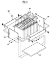
- FIG. 2 is an exploded perspective view of the battery module of FIG. 1 .
- the battery module 100 includes a plurality of battery cells 10 aligned in a first direction and each having terminal portions 11 and 12 on a first surface 14 thereof; a terminal connection member 150 connecting terminal portions 11 and 12 of first and second battery cells 10 adjacent to each other; and a housing 110, 120, 130 and 140 accommodating the plurality of battery cells 10 therein.
- the terminal connection member 150 includes a pair of contact portions 151 provided in parallel while being spaced apart from each other, and a support portion 152 connecting the contact portions 151 to each other.
- the pair of contact portions 151 may contact the terminal portions 11 and 12 of the first and second battery cells 10, respectively.
- the battery cell 10 may include a battery case having the first surface 14, and an electrode assembly and an electrolyte, accommodated in the battery case.
- the electrode assembly and the electrolyte generate energy through an electrochemical reaction therebetween.
- the first surface 14 of the battery cell 10 is provided with the terminal portions 11 and 12 electrically connected to the electrode assembly, and a vent 13 that is a passage along which gas generated inside the battery cell 10 is exhausted.
- the terminal portions 11 and 12 may be positive and negative electrode terminals 11 and 12 having different polarities from each other.
- the terminal portions 11 and 12 of the adjacent battery cells 10 may be electrically connected in series or parallel by the terminal connection member 150.
- a gasket 15 made of an electrical insulation material may be provided on the first surface 14 of the battery cell 10.
- the terminal portions 11 and 12 are protruded to the outside of the gasket 15.
- the terminal portions 11 and 12 of the adjacent battery cells 10 may be connected by the terminal connection member 150 on the gasket 15.
- the plurality of battery cells 10 may be aligned in the first direction so that wide surfaces of the battery cells 10 face each other.
- the aligned battery cells 10 may be fixed by the housing 110, 120, 130 and 140.
- the housing 110, 120, 130 and 140 may include a pair of end plates 110 and 120 facing the wide surfaces of the battery cells 10, and side and bottom plates 130 and 140 connecting the pair of end plates 110 and 120 to each other.
- the side plate 130 may support side surfaces of the battery cells 10, and the bottom plate 140 may support bottom surfaces of the battery cells 10.
- the pair of end plates 110 and 120, the side plate 130 and the bottom plate 140 may be connected by members such as bolts 20.
- FIG. 3 is a plan view of a terminal connection member according to an embodiment of the present invention.
- FIG. 4A is an enlarged view of portion A of FIG. 1 .
- FIG. 4B is an exploded perspective view of FIG. 4A .
- the terminal connection member 150 may include a pair of contact portions 151 and a support portion 152 connecting the pair of contact portions 151 to each other.
- the pair of contact portions 151 are spaced apart from each other at a predetermined interval, and the terminal portions 11 and 12 of first and second battery cells 10a and 10b that are adjacent battery cells 10 may contact the contact portions 151, respectively.
- the support portion 152 may maintain the spacing distance between the pair of contact portions 151 and adjust the interval between the pair of contact portions 151.
- the pair of contact portions 151 and the support portion 152 may be connected perpendicular to each other.
- the terminal connection member 150 may further include round portions 153, and the round portions 153 may be provided at one and the other ends of the support portion 152, respectively.
- the contact portion 151 may be connected to the round portion 153 at an end of the round portion 153.
- the round portion 153 is formed in a U-shape to connect between the support portion 151 and the contact portion 151.
- a first end 153a of the round portion 153 formed in the U-shape may be connected in parallel to the support portion 152, and a second end 153b of the round portion 153 may be connected perpendicular to the contact portion 151.
- the second end 153b of the round portion 153 and the contact portion 151 may be connected perpendicular to each other at a corner of the terminal portion 11 or 12.
- the U-shaped section (round portion 153) includes a first leg 153c connected to the support portion 152, a second leg 153d connected to the respective contact portion 151, and a joining portion 153e connected between the first leg 153c and the second leg 153d.
- the terminal portions 11 and 12 may be made of aluminum, copper, etc., and the terminal connection member 150 may be made of aluminum. Since the battery cell 10 according to this embodiment generates high current, the terminal portions 11 and 12 and the terminal connection member 150 may be provided with a predetermined strength so that the high current stably flows therethrough. That is, the terminal connection member 150 is entirely provided with a firm structure so as to have a predetermined strength, but may partially have flexibility provided by the round portion 153. For example, the round portion 153 is provided to facilitate the bending of the terminal connection member 150, and may have elasticity to facilitate the reciprocating movement of the pair of contact portions 151 connected to the support portion 152. Thus, the adhesion between the terminal portions 11 and 12 and the terminal connection member 150 can be improved while providing assembling tolerance to facilitate the connection between the terminal portions 11 and 12 and the terminal connection member 150.
- the terminal portions 11 and 12 of the first and second battery cells 10a and 10b may be electrically connected to each other by the terminal connection member 150.
- the terminal portion 11 of the first battery cell 10a may include a first facing portion 11a
- the terminal portion of the second battery cell 10b may include a second facing portion 12a facing the first facing portion 11a.
- the first and second battery cells 10a and 10b are aligned so that the first and second facing portions 11a and 12a face each other, and the first and second facing portions 11 a and 12a may be spaced apart from each other at a predetermined interval.
- the pair of contact portions 151 are pressed inward to be forcibly inserted between the first and second facing portions 11a and 12a.
- the pair of contact portions 151 may contact the first and second facing portions 11 a and 12a, respectively.
- the terminal connection member 150 may be bent by the round portions 153 while having the predetermined strength.
- the pair of contact portions 151 are bent by an external force so as to be easily inserted between the first and second facing portions 11a and 12a. After the external force is removed, the pair of contact portions 151 is restored to contact the respective first and second facing portions 11 a and 12a.
- At least one portion of each of the terminal portions 11 and 12 according to this embodiment may be formed as a hexahedron in which the first and second facing portions 11a and 12a have a quadrangular shape.
- the section of the contact portion 151 may be provided to correspond to the first or second facing portion 11a or 12a contacting the contact portion 151.
- the first and second facing portions 11 a and 12a and the contact portions 151 contact each other through their wide surfaces, and thus current can efficiently flow between the first and second battery cells 10a and 10b.
- FIG. 5 is a plan view of FIG. 4A .
- the terminal portions 11 and 12 of the first and second battery cells 10a and 10b and the terminal connection member 150 may be connected while being adhered closely to each other without being spaced apart.
- the terminal connection member 150 includes overlapping portions S respectively overlapped with the terminal portions 11 and 12 at the round portions 153, and the width of the overlapping portion S may be 0.2 to 0.6mm.
- the terminal connection member 150 and the terminal portions 11 and 12 can be physically firmly fixed by the fixing force of the housing, fixing the aligned battery cells 10 by pressing inward the aligned battery cells 10, and the restoring force between the contact portions 151 of the terminal connection member 150, forcibly inserted between the first and second facing portions.
- a separate process may be added to improve adhesion between the terminal connection member 150 and the terminal portions 11 and 12.
- the terminal connection member 150 and the terminal portions 11 and 12 are welded to each other by a laser beam L.
- the laser beam L is provided in parallel with the surfaces of the contact portions 151 and the terminal portions 11 and 12, which face each other, so as to connect the terminal connection member 150 and the terminal portions 11 and 12.
- the terminal portions 11 and 12 may include a positive electrode terminal 11 made of aluminum and a negative electrode terminal 12 made of copper, and the terminal connection member 150 may include a bus-bar made of aluminum.
- the positive electrode terminal 11 and the terminal connection member 150 are made of the same metal, so as to be easily adhered closely to each other.
- the laser beam L is provided adjacent to the negative electrode terminal 12, and accordingly, the interface of the terminal connection member 150 contacting the negative electrode terminal 12 is melted so that the terminal connection member 150 can be adhered closely to the negative electrode terminal 12.
- the terminal connection member 150 and the terminal portions 11 and 12 can be connected using relatively low power without forming the terminal connection portion 150 with clad metal (because the laser beam L is not provided in a direction perpendicular to the direction in which the terminal portions 11 and 12 and the terminal connection member 150 contact each other).
- the width of the overlapping portion S may be 0.2 to 0.6mm.
- the overlapping portion S is provided perpendicular to the direction in which the laser beam L is provided, and thus it is possible to prevent the transmission of the laser beam L. Accordingly, it is possible to prevent the battery cell 10, e.g., the electrode assembly and the electrolyte from being damaged by the laser beam L and heat generated by the laser beam L.
- the laser beam L is provided in the form of a beam to a target material by amplified laser and locally heats the target material with a high energy density for a short period of time, so that it is possible to minimize the thermal deformation and cooling time of the target material and to effectively perform welding even in a narrow area.
- the width of the overlapping portion S is less than 0.2mm, a portion of the laser beam L is transmitted through the overlapping portion S, and therefore, the battery cell 10 may be damaged.
- the width of the overlapping portion S exceeds 0.6mm, the size of the terminal connection member 150 is unnecessarily enlarged, and therefore, a short circuit between adjacent terminal connection members 150 may occur.
- the width of the overlapping portion S is preferably 0.2 to 0.6mm.
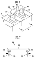
- FIG. 6 is a perspective view schematically showing a terminal connection member and a terminal portion according to another embodiment of the present invention.
- the terminal connection member 260 may connect the terminal portions 11 and 12 respectively provided to the first surfaces 14 of the first and second battery cells 10a and 10b.
- the terminal connection member 250 may include a pair of contact portions 251 provided in parallel with each other, a support portion 252 provided approximately perpendicular to the contact portions 251, and a round portion 253 provided to be easily bent between the contact portion 251 and the support portion 252.
- the pair of contact portions 251 may be provided to come in surface contact with the terminal portions 11 and 12, respectively. That is, the terminal portion 11 of the first battery cell 10a and the terminal portion 12 of the second battery cell 10b face each other while being spaced apart from each other at a predetermined interval.
- the terminal connection member 250 may be inserted into the interval between the terminal portions 11 and 12 in a direction perpendicular to the first surface 14. In this case, the round portions 253 adjacent to the contact portions 251 contact upper surfaces of the terminal portions 11 and 12, respectively, so as to guide the distance at which the contact portions 251 are inserted between the terminal portions 11 and 12.
- the terminal connection member 250 is inserted between the terminal portions 11 and 12 above the terminal portions 11 and 12. Thus, the terminal connection member 250 can be easily inserted between the terminal portions 11 and 12 even when the size of the battery cells 10 is small.
- FIGS. 7 to 9 Contents of these embodiments, except the following contents, are similar to those of the embodiment described with reference to FIGS. 1 to 6 , and therefore, their detailed descriptions will be omitted.
- FIG. 7 is a perspective view of a terminal connection member according to still another embodiment of the present invention.
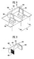
- FIG. 8 is a perspective view schematically showing a terminal connection member and a terminal portion according to still another embodiment of the present invention.
- the battery module may include a plurality of battery cells 10 and a terminal connection member 350 electrically connecting the battery cells 10 to each other.
- the battery cells 10 include adjacent first and second battery cells 10a and 10b, and terminal portions 11 and 12 respectively provided to the first and second battery cells 10a and 10b may be coupled to the terminal connection member 350.
- the terminal portions 11 and 12 of the first and second battery cells 10a and 10b face each other.
- the terminal portions 11 and 12 may be formed in the shape of a hexahedron, so that the quadrangular sections of the terminal portions 11 and 12 face each other.
- the terminal connection member 350 may include a pair of contact portions 351 provided in parallel with each other, and a support portion 352 maintaining the spacing distance between the pair of contact portions 351.
- the terminal connection member 350 may further include round portions 353. In this case, the round portions 353 are provided at one and the other ends of the support portion 352, respectively, and the contact portion 351 may be connected to an end of the round portion 353.
- the support portion 352 and the contact portion 351 are provided perpendicular to each other, and the contact portion 351 may have a stepped portion 355 recessed inwardly.
- the stepped portions 355 are respectively provided to the surfaces of the pair of contact portions 351, which face each other. Therefore, the stepped portions 355 respectively provided to the pair of contact portions 351 may also face each other.
- the terminal portions 11 and 12 of the first and second battery cells 10a and 10b may be electrically connected by the terminal connection member 350.
- the terminal portions 11 and 12 may be inserted between the pair of contact portions 351.
- the stepped portions 355 may be provided to have shapes corresponding to the terminal portions 11 and 12, respectively. Therefore, after the terminal portions 11 and 12 are mounted in the respective stepped portion 355, each of the terminal portions 11 and 12 may be provided to form the approximately same plane as peripheral portions of the stepped portion 355. Accordingly, the stepped portion 355 guides the position at which the terminal portion 11 or 12 is provided, and thus the terminal connection member 350 can be easily coupled to the first and second battery cells 10a and 10b.
- the terminal connection member 350 may electrically connect the first and second battery cells 10a and 10b and simultaneously fix the positions of the first and second battery cells 10a and 10b.
- the terminal portions 11 and 12 of the first and second battery cells 10a and 10b may be forcibly inserted between the pair of contact portions 351 of the terminal connection member 350, which have a predetermined strength.
- the first and second battery cells 10a and 10b are physically fixed to each other by the terminal connection member 350, and are not easily moved by an external impact, thereby efficiently performing the assembling of the battery module. Accordingly, the terminal connection member 350 can maintain the alignment of the battery cells 10 even when the housing fixing the battery cells 10 is omitted.
- FIG. 9 is a perspective view of a terminal connection member according to still another embodiment of the present invention.
- the terminal connection member 450 may be coupled to terminal portions of adjacent battery cells so that the battery cells are electrically connected to each other.
- the terminal connection member 450 may have a fastening portion 455 provided to a surface contacting the terminal portion.
- the terminal connection member 450 may include a pair of contact portions 451 directly contacting the respective terminal portions of the battery cells, a support portion 452 maintaining the spacing distance between the pair of contact portions 451, and round portions 453 facilitating the reciprocating movement of the pair of contact portions 451.
- the pair of contact portions 415 may be provided to face each other, and the fastening portion 455 may be provided to any one surface of each of the pair of contact portions 451.
- the fastening portion 455 may include surface roughness.
- the terminal connection member 450 may be inserted between the terminal portions of the adjacent battery cells.
- the terminal connection member 450 and the terminal portion are implemented as an electrical conductor, and may be made of metal or the like, which has a smooth surface.
- the fastening portion 455 increases the frictional force between the terminal connection member 450 and the terminal portion of the battery cell, so that it is possible to improve the coupling between the terminal connection member 450 and the fastening portion 455.
Landscapes
- Chemical & Material Sciences (AREA)
- Chemical Kinetics & Catalysis (AREA)
- Electrochemistry (AREA)
- General Chemical & Material Sciences (AREA)
- Engineering & Computer Science (AREA)
- Manufacturing & Machinery (AREA)
- Battery Mounting, Suspending (AREA)
- Connection Of Batteries Or Terminals (AREA)
Abstract
Description
- The present invention relates to a battery module, and more particularly, to a battery module capable of enhancing insulation property and safety.
- A high-power battery module using a non-aqueous electrolyte with high energy density has recently been developed. The high-power battery module is configured as a large-capacity battery module manufactured by connecting a plurality of battery cells in series so as to be used for driving devices, e.g., motors of electric vehicles and the like, which require high power.
- Typically, a battery module is configured with a plurality of battery cells, and the battery cell provides energy to an external electronic device through an electrochemical reaction. The plurality of battery cells is fixed by a housing so as to be used as one power source. In this case, the battery cells are electrically connected to one another by bus-bars or the like, and various studies have been conducted to stably and efficiently maintain high current flowing between the battery cells.
- Embodiments provide a battery module having a new terminal connection member.
- Embodiments also provide a battery module capable of improving efficiency and safety of current flow.
- According to the present invention, there is provided a battery module as defined in claim 1.
- Further embodiments of the invention could be learned from the dependent claims and following description.
- The accompanying drawings, together with the specification, illustrate exemplary embodiments of the present invention, and, together with the description, serve to explain the principles of the present invention.
-
FIG. 1 is a perspective view of a battery module according to an embodiment of the present invention. -
FIG. 2 is an exploded perspective view of the battery module ofFIG. 1 . -
FIG. 3 is a plan view of a terminal connection member according to an embodiment of the present invention. -
FIG. 4A is an enlarged view of portion A ofFIG. 1 . -
FIG. 4B is an exploded perspective view ofFIG. 4A . -
FIG. 5 is a plan view ofFIG. 4A . -
FIG. 6 is a perspective view schematically showing a terminal connection member and a terminal portion according to another embodiment of the present invention. -
FIG. 7 is a perspective view of a terminal connection member according to still another embodiment of the present invention. -
FIG. 8 is a perspective view schematically showing a terminal connection member and a terminal portion according to still another embodiment of the present invention. -
FIG. 9 is a perspective view of a terminal connection member according to still another embodiment of the present invention. - In the following detailed description, only certain exemplary embodiments of the present invention have been shown and described, simply by way of illustration. When an element is referred to as being "on" another element, it can be directly on the another element or be indirectly on the another element with one or more intervening elements interposed therebetween. Also, when an element is referred to as being "connected to" another element, it can be directly connected to the another element or be indirectly connected to the another element with one or more intervening elements interposed therebetween. Hereinafter, like reference numerals refer to like elements. In the drawings, the thickness or size of layers are exaggerated for clarity and not necessarily drawn to scale.
-
FIG. 1 is a perspective view of a battery module according to an embodiment of the present invention.FIG. 2 is an exploded perspective view of the battery module ofFIG. 1 . - The
battery module 100 according to this embodiment includes a plurality ofbattery cells 10 aligned in a first direction and each havingterminal portions first surface 14 thereof; aterminal connection member 150 connectingterminal portions second battery cells 10 adjacent to each other; and ahousing battery cells 10 therein. Theterminal connection member 150 includes a pair ofcontact portions 151 provided in parallel while being spaced apart from each other, and asupport portion 152 connecting thecontact portions 151 to each other. The pair ofcontact portions 151 may contact theterminal portions second battery cells 10, respectively. - The
battery cell 10 may include a battery case having thefirst surface 14, and an electrode assembly and an electrolyte, accommodated in the battery case. The electrode assembly and the electrolyte generate energy through an electrochemical reaction therebetween. Thefirst surface 14 of thebattery cell 10 is provided with theterminal portions vent 13 that is a passage along which gas generated inside thebattery cell 10 is exhausted. For example, theterminal portions negative electrode terminals terminal portions adjacent battery cells 10 may be electrically connected in series or parallel by theterminal connection member 150. Agasket 15 made of an electrical insulation material may be provided on thefirst surface 14 of thebattery cell 10. Theterminal portions gasket 15. Theterminal portions adjacent battery cells 10 may be connected by theterminal connection member 150 on thegasket 15. - The plurality of
battery cells 10 may be aligned in the first direction so that wide surfaces of thebattery cells 10 face each other. The alignedbattery cells 10 may be fixed by thehousing housing end plates battery cells 10, and side andbottom plates end plates side plate 130 may support side surfaces of thebattery cells 10, and thebottom plate 140 may support bottom surfaces of thebattery cells 10. The pair ofend plates side plate 130 and thebottom plate 140 may be connected by members such asbolts 20. -
FIG. 3 is a plan view of a terminal connection member according to an embodiment of the present invention.FIG. 4A is an enlarged view of portion A ofFIG. 1 .FIG. 4B is an exploded perspective view ofFIG. 4A . - Referring to
FIGS. 3, 4A and4B , theterminal connection member 150 according to this embodiment may include a pair ofcontact portions 151 and asupport portion 152 connecting the pair ofcontact portions 151 to each other. In this case, the pair ofcontact portions 151 are spaced apart from each other at a predetermined interval, and theterminal portions second battery cells adjacent battery cells 10 may contact thecontact portions 151, respectively. Thesupport portion 152 may maintain the spacing distance between the pair ofcontact portions 151 and adjust the interval between the pair ofcontact portions 151. For example, the pair ofcontact portions 151 and thesupport portion 152 may be connected perpendicular to each other. - The
terminal connection member 150 may further includeround portions 153, and theround portions 153 may be provided at one and the other ends of thesupport portion 152, respectively. Thecontact portion 151 may be connected to theround portion 153 at an end of theround portion 153. For example, theround portion 153 is formed in a U-shape to connect between thesupport portion 151 and thecontact portion 151. Afirst end 153a of theround portion 153 formed in the U-shape may be connected in parallel to thesupport portion 152, and asecond end 153b of theround portion 153 may be connected perpendicular to thecontact portion 151. Thesecond end 153b of theround portion 153 and thecontact portion 151 may be connected perpendicular to each other at a corner of theterminal portion first leg 153c connected to thesupport portion 152, asecond leg 153d connected to therespective contact portion 151, and a joiningportion 153e connected between thefirst leg 153c and thesecond leg 153d. - The
terminal portions terminal connection member 150 may be made of aluminum. Since thebattery cell 10 according to this embodiment generates high current, theterminal portions terminal connection member 150 may be provided with a predetermined strength so that the high current stably flows therethrough. That is, theterminal connection member 150 is entirely provided with a firm structure so as to have a predetermined strength, but may partially have flexibility provided by theround portion 153. For example, theround portion 153 is provided to facilitate the bending of theterminal connection member 150, and may have elasticity to facilitate the reciprocating movement of the pair ofcontact portions 151 connected to thesupport portion 152. Thus, the adhesion between theterminal portions terminal connection member 150 can be improved while providing assembling tolerance to facilitate the connection between theterminal portions terminal connection member 150. - When one of the
adjacent battery cells 10 is referred to as afirst battery cell 10a and the other of theadjacent battery cells 10 is referred to as asecond battery cell 10b, theterminal portions second battery cells terminal connection member 150. Theterminal portion 11 of thefirst battery cell 10a may include a first facingportion 11a, and the terminal portion of thesecond battery cell 10b may include a second facingportion 12a facing the first facingportion 11a. The first andsecond battery cells second facing portions portions terminal connection member 150, the pair ofcontact portions 151 are pressed inward to be forcibly inserted between the first andsecond facing portions contact portions 151 may contact the first and second facingportions - As described above, the
terminal connection member 150 may be bent by theround portions 153 while having the predetermined strength. The pair ofcontact portions 151 are bent by an external force so as to be easily inserted between the first andsecond facing portions contact portions 151 is restored to contact the respective first and second facingportions terminal portions second facing portions contact portion 151 may be provided to correspond to the first or second facingportion contact portion 151. The first and second facingportions contact portions 151 contact each other through their wide surfaces, and thus current can efficiently flow between the first andsecond battery cells -
FIG. 5 is a plan view ofFIG. 4A . - Referring to
FIG. 5 , theterminal portions second battery cells terminal connection member 150 may be connected while being adhered closely to each other without being spaced apart. In this case, theterminal connection member 150 includes overlapping portions S respectively overlapped with theterminal portions round portions 153, and the width of the overlapping portion S may be 0.2 to 0.6mm. Theterminal connection member 150 and theterminal portions battery cells 10 by pressing inward the alignedbattery cells 10, and the restoring force between thecontact portions 151 of theterminal connection member 150, forcibly inserted between the first and second facing portions. - A separate process may be added to improve adhesion between the
terminal connection member 150 and theterminal portions terminal connection member 150 and theterminal portions contact portions 151 and theterminal portions terminal connection member 150 and theterminal portions - For example, the
terminal portions positive electrode terminal 11 made of aluminum and anegative electrode terminal 12 made of copper, and theterminal connection member 150 may include a bus-bar made of aluminum. Thepositive electrode terminal 11 and theterminal connection member 150 are made of the same metal, so as to be easily adhered closely to each other. In case of thenegative electrode terminal 12 and theterminal connection member 150, the laser beam L is provided adjacent to thenegative electrode terminal 12, and accordingly, the interface of theterminal connection member 150 contacting thenegative electrode terminal 12 is melted so that theterminal connection member 150 can be adhered closely to thenegative electrode terminal 12. Thus, even when the positive andnegative electrode terminals terminal connection member 150 and theterminal portions terminal connection portion 150 with clad metal (because the laser beam L is not provided in a direction perpendicular to the direction in which theterminal portions terminal connection member 150 contact each other). - In the
terminal connection member 150, the width of the overlapping portion S may be 0.2 to 0.6mm. The overlapping portion S is provided perpendicular to the direction in which the laser beam L is provided, and thus it is possible to prevent the transmission of the laser beam L. Accordingly, it is possible to prevent thebattery cell 10, e.g., the electrode assembly and the electrolyte from being damaged by the laser beam L and heat generated by the laser beam L. The laser beam L is provided in the form of a beam to a target material by amplified laser and locally heats the target material with a high energy density for a short period of time, so that it is possible to minimize the thermal deformation and cooling time of the target material and to effectively perform welding even in a narrow area. In a case where the width of the overlapping portion S is less than 0.2mm, a portion of the laser beam L is transmitted through the overlapping portion S, and therefore, thebattery cell 10 may be damaged. In a case where the width of the overlapping portion S exceeds 0.6mm, the size of theterminal connection member 150 is unnecessarily enlarged, and therefore, a short circuit between adjacentterminal connection members 150 may occur. Thus, the width of the overlapping portion S is preferably 0.2 to 0.6mm. -
FIG. 6 is a perspective view schematically showing a terminal connection member and a terminal portion according to another embodiment of the present invention. - Referring to
FIG. 6 , in the battery module according to this embodiment, the terminal connection member 260 may connect theterminal portions first surfaces 14 of the first andsecond battery cells terminal connection member 250 may include a pair ofcontact portions 251 provided in parallel with each other, asupport portion 252 provided approximately perpendicular to thecontact portions 251, and around portion 253 provided to be easily bent between thecontact portion 251 and thesupport portion 252. - In the
terminal connection member 250, the pair ofcontact portions 251 may be provided to come in surface contact with theterminal portions terminal portion 11 of thefirst battery cell 10a and theterminal portion 12 of thesecond battery cell 10b face each other while being spaced apart from each other at a predetermined interval. Theterminal connection member 250 may be inserted into the interval between theterminal portions first surface 14. In this case, theround portions 253 adjacent to thecontact portions 251 contact upper surfaces of theterminal portions contact portions 251 are inserted between theterminal portions terminal connection member 250 is inserted between theterminal portions terminal portions terminal connection member 250 can be easily inserted between theterminal portions battery cells 10 is small. - Hereinafter, other embodiments of the present invention will be described with reference to
FIGS. 7 to 9 . Contents of these embodiments, except the following contents, are similar to those of the embodiment described with reference toFIGS. 1 to 6 , and therefore, their detailed descriptions will be omitted. -
FIG. 7 is a perspective view of a terminal connection member according to still another embodiment of the present invention.FIG. 8 is a perspective view schematically showing a terminal connection member and a terminal portion according to still another embodiment of the present invention. - Referring to
FIGS. 7 and8 , the battery module according to this embodiment may include a plurality ofbattery cells 10 and aterminal connection member 350 electrically connecting thebattery cells 10 to each other. Thebattery cells 10 include adjacent first andsecond battery cells terminal portions second battery cells terminal connection member 350. - The
terminal portions second battery cells terminal portions terminal portions terminal connection member 350 may include a pair ofcontact portions 351 provided in parallel with each other, and asupport portion 352 maintaining the spacing distance between the pair ofcontact portions 351. Theterminal connection member 350 may further includeround portions 353. In this case, theround portions 353 are provided at one and the other ends of thesupport portion 352, respectively, and thecontact portion 351 may be connected to an end of theround portion 353. - The
support portion 352 and thecontact portion 351 are provided perpendicular to each other, and thecontact portion 351 may have a steppedportion 355 recessed inwardly. The steppedportions 355 are respectively provided to the surfaces of the pair ofcontact portions 351, which face each other. Therefore, the steppedportions 355 respectively provided to the pair ofcontact portions 351 may also face each other. - The
terminal portions second battery cells terminal connection member 350. Theterminal portions contact portions 351. In this case, the steppedportions 355 may be provided to have shapes corresponding to theterminal portions terminal portions portion 355, each of theterminal portions portion 355. Accordingly, the steppedportion 355 guides the position at which theterminal portion terminal connection member 350 can be easily coupled to the first andsecond battery cells - The
terminal connection member 350 according to this embodiment may electrically connect the first andsecond battery cells second battery cells terminal portions second battery cells contact portions 351 of theterminal connection member 350, which have a predetermined strength. Thus, the first andsecond battery cells terminal connection member 350, and are not easily moved by an external impact, thereby efficiently performing the assembling of the battery module. Accordingly, theterminal connection member 350 can maintain the alignment of thebattery cells 10 even when the housing fixing thebattery cells 10 is omitted. -
FIG. 9 is a perspective view of a terminal connection member according to still another embodiment of the present invention. - The
terminal connection member 450 according to this embodiment may be coupled to terminal portions of adjacent battery cells so that the battery cells are electrically connected to each other. Theterminal connection member 450 may have afastening portion 455 provided to a surface contacting the terminal portion. Theterminal connection member 450 may include a pair ofcontact portions 451 directly contacting the respective terminal portions of the battery cells, asupport portion 452 maintaining the spacing distance between the pair ofcontact portions 451, andround portions 453 facilitating the reciprocating movement of the pair ofcontact portions 451. In this case, the pair of contact portions 415 may be provided to face each other, and thefastening portion 455 may be provided to any one surface of each of the pair ofcontact portions 451. For example, thefastening portion 455 may include surface roughness. - The
terminal connection member 450 may be inserted between the terminal portions of the adjacent battery cells. Theterminal connection member 450 and the terminal portion are implemented as an electrical conductor, and may be made of metal or the like, which has a smooth surface. Thefastening portion 455 increases the frictional force between theterminal connection member 450 and the terminal portion of the battery cell, so that it is possible to improve the coupling between theterminal connection member 450 and thefastening portion 455.
Claims (15)
- A battery module, comprising:a first battery cell (10a), the first battery cell having a first terminal portion (11);a second battery cell (10b), the second battery cell having a second terminal portion (12); anda terminal connection member (150, 250, 350, 450) connecting the first andsecond terminal portions (11, 12) together, the terminal connection member (150, 250, 350, 450) including:a first contact portion (151, 251, 351, 451), the first contact portion (151, 251, 351, 451) having a first facing portion contacting the first terminal portion (11);a second contact portion (151, 251, 351, 451), the second contact portion (151, 251, 351, 451) having a second facing portion contacting the second terminal portion (12), the second facing portion being spaced apart from the first facing portion in a first direction, an outermost portion of the first contact portion (151, 251, 351, 451) being spaced apart in the first direction from an outermost portion of the second contact portion (151, 251, 351, 451) by a first distance;anda support portion (152, 252, 352, 452), the support portion (152, 252, 352, 452) extending in the first direction between the first contact portion (151, 251, 351, 451) and the second contact portion (151, 251, 351, 451) and electrically and physically connecting the first and second contact portions (151, 251, 351, 451), the support portion (152, 252, 352, 452) having an overall length in the first direction that is greater than the first distance.
- The battery module of claim 1, wherein the support portion (152, 252, 352, 452) includes respective U-shaped sections (153, 253, 353, 453) connecting the support portion (152, 252, 352, 452) to the first and second contact portions (151, 251, 351, 451), each U-shaped section (153, 253, 353, 453) including a first leg (153c) connected to the support portion (152, 252, 352, 452), a second leg (153d) connected to the respective contact portion (151, 251, 351, 451), and a joining portion (153e) connected between the first leg (153c) and the second leg (153d).
- The battery module of claim 2, wherein each U-shaped section (153, 253, 353, 453) is in the shape of a continuous curve or a trilateral member.
- The battery module of claim 2, wherein the contact portions (151, 251, 351, 451) are connected to a side of the respective U-shaped sections (153, 253, 353, 453) of the support portion (152, 352, 352, 452).
- The battery module of one of the preceding claims, wherein the first facing portion and the second facing portion of the contact portions (351) face towards one another, the first and second facing portions contacting the respective terminal portions (11, 12) with the respective terminal portions (11, 12) interposed between the first facing portion and the second facing portion.
- The battery module of one of claims 1 through 4, wherein the first facing portion and the second facing portion of the contact portions (151, 252, 451) face away from one another, the first and second facing portions contacting the respective terminal portions (11, 12) with the first and second facing portions interposed between the respective terminal portions (11, 12).
- The battery module of one of the preceding claims, wherein the first and second facing portions of the contact portions (451) are roughened.
- The battery module of one of the preceding claims, wherein the terminal connection member (150, 250, 350, 450) is elastically deformable in the first direction, the terminal connection member (150, 250, 350, 450) being configured to press the first and second facing portions against the first and second terminal portions (11, 12), respectively.
- The battery module of one of the preceding claims, wherein the first and second facing portions are welded to the first and second terminal portions (11, 12), respectively.
- The battery module of one of the preceding claims, wherein the terminal portions (11, 12) project away from the battery cells and the terminal connection member (250) is installed from an end of the terminal portions (11, 12), such that the terminal portions (11, 12) are interposed between the support portion (252) and a case of the battery cells (10).
- The battery module of one of claims 1 through 9, wherein the terminal portions (11, 12) project away from the battery cells (10a, 10b) and have first and second side surfaces extending in parallel to the first direction, the terminal connection member (150, 350, 450) is installed from a side of the terminal portions (11, 12), such that the support portion (152, 352, 452) overlaps the first or second side surfaces of the terminal portions (11, 12).
- The battery module of claim 11, wherein:the first battery cell (10a) includes a third terminal portion (12), the third terminal portion (12) being spaced apart from the first terminal portion (11) in a second direction orthogonal to the first direction,the second battery cell (10b) includes a fourth terminal portion (11) spaced apart from the second terminal portion (12) in the second direction, andthe support portion (152, 352, 452) is between the first terminal portion (11) andthe third terminal portion (12), and between the second terminal portion (12) and the fourth terminal portion (11).
- The battery module of one of the preceding claims, wherein the terminal portion (11) is made of aluminum, the second terminal portion (12) is made of copper and the terminal connection member (150, 250, 350, 450) is made of aluminum.
- The battery module of one of the preceding claims, wherein the support portion (152, 252, 352, 452) has an overall length in the first direction that is 0.2 to 0.6 mm greater than the first distance.
- The battery module of one of the preceding claims, wherein the battery module (100) further includes a housing (110, 120, 130, 140) accommodating the plurality of battery cells (10) therein.
Applications Claiming Priority (2)
| Application Number | Priority Date | Filing Date | Title |
|---|---|---|---|
| US201361754019P | 2013-01-18 | 2013-01-18 | |
| US14/105,680 US9799872B2 (en) | 2013-01-18 | 2013-12-13 | Battery module |
Publications (2)
| Publication Number | Publication Date |
|---|---|
| EP2757611A1 true EP2757611A1 (en) | 2014-07-23 |
| EP2757611B1 EP2757611B1 (en) | 2016-03-30 |
Family
ID=49917626
Family Applications (1)
| Application Number | Title | Priority Date | Filing Date |
|---|---|---|---|
| EP14151046.1A Active EP2757611B1 (en) | 2013-01-18 | 2014-01-14 | Battery module |
Country Status (6)
| Country | Link |
|---|---|
| US (1) | US9799872B2 (en) |
| EP (1) | EP2757611B1 (en) |
| JP (1) | JP6411742B2 (en) |
| KR (1) | KR102198006B1 (en) |
| CN (1) | CN103943808B (en) |
| ES (1) | ES2572392T3 (en) |
Cited By (5)
| Publication number | Priority date | Publication date | Assignee | Title |
|---|---|---|---|---|
| EP3113248A1 (en) * | 2015-06-30 | 2017-01-04 | Kabushiki Kaisha Toshiba | Bus bar and battery module |
| US9972811B2 (en) | 2015-08-11 | 2018-05-15 | Kabushiki Kaisha Toshiba | Battery module |
| US9979003B2 (en) | 2015-05-21 | 2018-05-22 | Kabushiki Kaisha Toshiba | Bus bar including two conductive concave portions and battery module |
| EP3985789A4 (en) * | 2019-08-02 | 2023-01-18 | LG Energy Solution, Ltd. | BUS BAR HAVING A SURFACE PATTERN AND BATTERY MODULE COMPRISING THE SAME |
| EP4546551A1 (en) * | 2023-10-24 | 2025-04-30 | Bayerische Motoren Werke Aktiengesellschaft | Thermal conduction efficient terminal design |
Families Citing this family (27)
| Publication number | Priority date | Publication date | Assignee | Title |
|---|---|---|---|---|
| JP6724298B2 (en) * | 2014-07-31 | 2020-07-15 | 株式会社Gsユアサ | Power supply module |
| US10396405B2 (en) * | 2014-11-10 | 2019-08-27 | Te Connectivity Corporation | Bus bar for a battery connector system |
| JP6156410B2 (en) * | 2015-02-25 | 2017-07-05 | トヨタ自動車株式会社 | Rankine cycle system |
| KR102341402B1 (en) * | 2015-05-15 | 2021-12-20 | 삼성에스디아이 주식회사 | Battery module |
| JP1546964S (en) * | 2015-10-28 | 2016-04-04 | ||
| ES2779993T3 (en) * | 2016-06-03 | 2020-08-21 | E-Seven Systems Tech Management Ltd | Battery with battery sections and contact section element |
| KR102235650B1 (en) * | 2016-06-17 | 2021-04-01 | 에스케이이노베이션 주식회사 | Secondary battery module, and secondary battery pack including the same |
| JP6699464B2 (en) | 2016-09-05 | 2020-05-27 | 株式会社オートネットワーク技術研究所 | Connection module |
| JP2018049823A (en) * | 2016-09-14 | 2018-03-29 | 旭化成株式会社 | Power storage module having vibration-proof connection structure |
| KR102115482B1 (en) * | 2016-09-29 | 2020-05-26 | 주식회사 엘지화학 | Battery pack |
| KR102067714B1 (en) * | 2016-11-17 | 2020-01-17 | 주식회사 엘지화학 | Battery module and battery pack including the same |
| JP2018113153A (en) * | 2017-01-11 | 2018-07-19 | トヨタ自動車株式会社 | Battery pack |
| JP6688465B2 (en) * | 2017-03-13 | 2020-04-28 | トヨタ自動車株式会社 | Battery pack |
| KR102316490B1 (en) * | 2017-03-22 | 2021-10-22 | 주식회사 엘지화학 | Bus-bar Assembly with Improved Reliability of Current Breaking Together with Compact Structure and Battery Module Comprising the Same |
| KR102766756B1 (en) * | 2017-04-20 | 2025-02-14 | 에이일이삼 시스템즈 엘엘씨 | Configure the battery tab |
| KR102242249B1 (en) * | 2018-02-12 | 2021-04-20 | 주식회사 엘지화학 | Current interrupt device and battery module including the same |
| JP7041842B2 (en) * | 2018-03-26 | 2022-03-25 | トヨタ自動車株式会社 | Assembled battery and manufacturing method of assembled battery |
| KR102258177B1 (en) * | 2018-09-20 | 2021-05-28 | 주식회사 엘지에너지솔루션 | Battery module, battery pack comprising the battery module and vehicle comprising the battery pack |
| JP2022013957A (en) * | 2018-10-29 | 2022-01-19 | 三洋電機株式会社 | Bus bar and battery module |
| FR3111238B1 (en) * | 2020-06-04 | 2022-07-29 | Accumulateurs Fixes | CONNECTING MECHANISM FOR CONNECTING TWO ACCUMULATORS |
| CN115769452B (en) * | 2020-07-27 | 2025-08-15 | 株式会社村田制作所 | Power supply system and connection structure of connection terminal and bus bar |
| KR102935639B1 (en) * | 2020-10-06 | 2026-03-05 | 주식회사 엘지에너지솔루션 | Battery module and battery pack including the same and vehicle including the same |
| CN115347327A (en) * | 2021-05-14 | 2022-11-15 | 中创新航科技股份有限公司 | Battery pack and battery pack grouping method |
| US12021366B2 (en) * | 2022-07-18 | 2024-06-25 | Bentek Corporation | Neutral busbar stand assembly and method |
| WO2024081145A1 (en) * | 2022-10-12 | 2024-04-18 | Enphase Energy, Inc. | Chassis configured for use with prismatic battery cells |
| CN116759756A (en) * | 2023-06-15 | 2023-09-15 | 蜂巢能源科技股份有限公司 | Battery module, battery module assembly method and power battery pack |
| DE102024207324B4 (en) * | 2024-08-01 | 2026-03-12 | Volkswagen Aktiengesellschaft | Method for manufacturing a battery system and motor vehicle with battery system |
Citations (3)
| Publication number | Priority date | Publication date | Assignee | Title |
|---|---|---|---|---|
| US20090159311A1 (en) * | 2007-12-25 | 2009-06-25 | Weixin Zheng | Battery system for a vehicle with severable connections |
| US20100151312A1 (en) * | 2008-12-11 | 2010-06-17 | Samsung Sdi Co., Ltd. | Battery module |
| EP2538469A2 (en) * | 2011-06-23 | 2012-12-26 | Samsung SDI Co., Ltd. | Battery pack |
Family Cites Families (8)
| Publication number | Priority date | Publication date | Assignee | Title |
|---|---|---|---|---|
| JP5137354B2 (en) * | 2006-07-31 | 2013-02-06 | 三洋電機株式会社 | Power supply |
| JP5252836B2 (en) * | 2007-05-29 | 2013-07-31 | 三洋電機株式会社 | Pack battery |
| JP4935802B2 (en) * | 2008-12-10 | 2012-05-23 | パナソニック株式会社 | Battery module and assembled battery module using the same |
| KR101050318B1 (en) | 2009-04-16 | 2011-07-19 | 에스비리모티브 주식회사 | Secondary battery module |
| KR20110055255A (en) | 2009-11-19 | 2011-05-25 | 에스비리모티브 주식회사 | Bus bar and battery module with same |
| DE102010033437A1 (en) * | 2010-08-04 | 2012-02-09 | Johnson Controls Hybrid And Recycling Gmbh | Electrical connection arrangement and electrical connection element and accumulator arrangement therefor |
| KR101275816B1 (en) * | 2010-12-31 | 2013-06-18 | 삼성에스디아이 주식회사 | Battery module |
| JP5447542B2 (en) * | 2012-01-24 | 2014-03-19 | 株式会社オートネットワーク技術研究所 | Connection structure of battery output terminal and terminal bracket |
-
2013
- 2013-12-13 US US14/105,680 patent/US9799872B2/en active Active
-
2014
- 2014-01-14 EP EP14151046.1A patent/EP2757611B1/en active Active
- 2014-01-14 ES ES14151046T patent/ES2572392T3/en active Active
- 2014-01-14 KR KR1020140004350A patent/KR102198006B1/en active Active
- 2014-01-16 CN CN201410019533.4A patent/CN103943808B/en active Active
- 2014-01-17 JP JP2014006729A patent/JP6411742B2/en active Active
Patent Citations (3)
| Publication number | Priority date | Publication date | Assignee | Title |
|---|---|---|---|---|
| US20090159311A1 (en) * | 2007-12-25 | 2009-06-25 | Weixin Zheng | Battery system for a vehicle with severable connections |
| US20100151312A1 (en) * | 2008-12-11 | 2010-06-17 | Samsung Sdi Co., Ltd. | Battery module |
| EP2538469A2 (en) * | 2011-06-23 | 2012-12-26 | Samsung SDI Co., Ltd. | Battery pack |
Cited By (7)
| Publication number | Priority date | Publication date | Assignee | Title |
|---|---|---|---|---|
| US9979003B2 (en) | 2015-05-21 | 2018-05-22 | Kabushiki Kaisha Toshiba | Bus bar including two conductive concave portions and battery module |
| EP3113248A1 (en) * | 2015-06-30 | 2017-01-04 | Kabushiki Kaisha Toshiba | Bus bar and battery module |
| US10199625B2 (en) | 2015-06-30 | 2019-02-05 | Kabushiki Kaisha Toshiba | Bus bar including thick portion connected to thin portion by bend portions and battery module including the same |
| US9972811B2 (en) | 2015-08-11 | 2018-05-15 | Kabushiki Kaisha Toshiba | Battery module |
| EP3985789A4 (en) * | 2019-08-02 | 2023-01-18 | LG Energy Solution, Ltd. | BUS BAR HAVING A SURFACE PATTERN AND BATTERY MODULE COMPRISING THE SAME |
| US12567654B2 (en) | 2019-08-02 | 2026-03-03 | Lg Energy Solution, Ltd. | Bus bar having surface pattern and battery module comprising same |
| EP4546551A1 (en) * | 2023-10-24 | 2025-04-30 | Bayerische Motoren Werke Aktiengesellschaft | Thermal conduction efficient terminal design |
Also Published As
| Publication number | Publication date |
|---|---|
| KR20140093619A (en) | 2014-07-28 |
| US20140205889A1 (en) | 2014-07-24 |
| ES2572392T3 (en) | 2016-05-31 |
| JP2014138000A (en) | 2014-07-28 |
| KR102198006B1 (en) | 2021-01-04 |
| CN103943808A (en) | 2014-07-23 |
| CN103943808B (en) | 2017-12-29 |
| EP2757611B1 (en) | 2016-03-30 |
| US9799872B2 (en) | 2017-10-24 |
| JP6411742B2 (en) | 2018-10-24 |
Similar Documents
| Publication | Publication Date | Title |
|---|---|---|
| EP2757611B1 (en) | Battery module | |
| CN101395490B (en) | Voltage detection component and battery module using the voltage detection component | |
| US10115954B2 (en) | Battery module | |
| EP2819210B1 (en) | Battery module | |
| CN104737328B (en) | Supply unit and possess the electric vehicle of supply unit and the manufacture method of electrical storage device, supply unit | |
| US8329324B2 (en) | Voltage sensing member and battery module employed with the same | |
| US8859130B2 (en) | Battery cover for a high voltage automotive battery | |
| KR101943655B1 (en) | Electric storage device | |
| EP3255703B1 (en) | Battery pack | |
| EP2808927A1 (en) | Battery module | |
| CN112889180A (en) | Battery module | |
| JP2009529218A (en) | Battery module | |
| EP1991880A1 (en) | Voltage sensing member and battery module employed with the same | |
| US9627674B2 (en) | Battery module | |
| JP2013206844A (en) | Electrode connection structure in laminate cell battery | |
| US12113241B2 (en) | Battery module | |
| KR101661869B1 (en) | Electrical storage module | |
| CN114051673B (en) | Power storage group | |
| KR101699865B1 (en) | Battery Module Having Direct Connecting Type Volage Sensing Part | |
| CN104919618B (en) | Battery Modules and Packs | |
| JP2015015237A (en) | Battery pack | |
| US20150221924A1 (en) | Battery module | |
| JP5558878B2 (en) | Assembled battery, resistance welding method, and assembled battery manufacturing method | |
| JP2013026191A (en) | Power supply unit | |
| US10069178B2 (en) | Battery cell having connecting protrusion for voltage sensing and battery module comprising the same |
Legal Events
| Date | Code | Title | Description |
|---|---|---|---|
| PUAI | Public reference made under article 153(3) epc to a published international application that has entered the european phase |
Free format text: ORIGINAL CODE: 0009012 |
|
| 17P | Request for examination filed |
Effective date: 20140114 |
|
| AK | Designated contracting states |
Kind code of ref document: A1 Designated state(s): AL AT BE BG CH CY CZ DE DK EE ES FI FR GB GR HR HU IE IS IT LI LT LU LV MC MK MT NL NO PL PT RO RS SE SI SK SM TR |
|
| AX | Request for extension of the european patent |
Extension state: BA ME |
|
| R17P | Request for examination filed (corrected) |
Effective date: 20150120 |
|
| RBV | Designated contracting states (corrected) |
Designated state(s): AL AT BE BG CH CY CZ DE DK EE ES FI FR GB GR HR HU IE IS IT LI LT LU LV MC MK MT NL NO PL PT RO RS SE SI SK SM TR |
|
| GRAP | Despatch of communication of intention to grant a patent |
Free format text: ORIGINAL CODE: EPIDOSNIGR1 |
|
| RIC1 | Information provided on ipc code assigned before grant |
Ipc: H01M 2/10 20060101AFI20150821BHEP Ipc: H01M 2/20 20060101ALI20150821BHEP Ipc: H01M 2/30 20060101ALI20150821BHEP |
|
| INTG | Intention to grant announced |
Effective date: 20150930 |
|
| GRAS | Grant fee paid |
Free format text: ORIGINAL CODE: EPIDOSNIGR3 |
|
| GRAA | (expected) grant |
Free format text: ORIGINAL CODE: 0009210 |
|
| AK | Designated contracting states |
Kind code of ref document: B1 Designated state(s): AL AT BE BG CH CY CZ DE DK EE ES FI FR GB GR HR HU IE IS IT LI LT LU LV MC MK MT NL NO PL PT RO RS SE SI SK SM TR |
|
| REG | Reference to a national code |
Ref country code: GB Ref legal event code: FG4D |
|
| REG | Reference to a national code |
Ref country code: CH Ref legal event code: EP |
|
| REG | Reference to a national code |
Ref country code: AT Ref legal event code: REF Ref document number: 786245 Country of ref document: AT Kind code of ref document: T Effective date: 20160415 |
|
| REG | Reference to a national code |
Ref country code: IE Ref legal event code: FG4D |
|
| REG | Reference to a national code |
Ref country code: DE Ref legal event code: R096 Ref document number: 602014001233 Country of ref document: DE |
|
| REG | Reference to a national code |
Ref country code: ES Ref legal event code: FG2A Ref document number: 2572392 Country of ref document: ES Kind code of ref document: T3 Effective date: 20160531 |
|
| REG | Reference to a national code |
Ref country code: LT Ref legal event code: MG4D |
|
| PG25 | Lapsed in a contracting state [announced via postgrant information from national office to epo] |
Ref country code: NO Free format text: LAPSE BECAUSE OF FAILURE TO SUBMIT A TRANSLATION OF THE DESCRIPTION OR TO PAY THE FEE WITHIN THE PRESCRIBED TIME-LIMIT Effective date: 20160630 Ref country code: HR Free format text: LAPSE BECAUSE OF FAILURE TO SUBMIT A TRANSLATION OF THE DESCRIPTION OR TO PAY THE FEE WITHIN THE PRESCRIBED TIME-LIMIT Effective date: 20160330 Ref country code: GR Free format text: LAPSE BECAUSE OF FAILURE TO SUBMIT A TRANSLATION OF THE DESCRIPTION OR TO PAY THE FEE WITHIN THE PRESCRIBED TIME-LIMIT Effective date: 20160701 Ref country code: FI Free format text: LAPSE BECAUSE OF FAILURE TO SUBMIT A TRANSLATION OF THE DESCRIPTION OR TO PAY THE FEE WITHIN THE PRESCRIBED TIME-LIMIT Effective date: 20160330 |
|
| REG | Reference to a national code |
Ref country code: NL Ref legal event code: MP Effective date: 20160330 |
|
| REG | Reference to a national code |
Ref country code: AT Ref legal event code: MK05 Ref document number: 786245 Country of ref document: AT Kind code of ref document: T Effective date: 20160330 |
|
| PG25 | Lapsed in a contracting state [announced via postgrant information from national office to epo] |
Ref country code: LV Free format text: LAPSE BECAUSE OF FAILURE TO SUBMIT A TRANSLATION OF THE DESCRIPTION OR TO PAY THE FEE WITHIN THE PRESCRIBED TIME-LIMIT Effective date: 20160330 Ref country code: RS Free format text: LAPSE BECAUSE OF FAILURE TO SUBMIT A TRANSLATION OF THE DESCRIPTION OR TO PAY THE FEE WITHIN THE PRESCRIBED TIME-LIMIT Effective date: 20160330 Ref country code: SE Free format text: LAPSE BECAUSE OF FAILURE TO SUBMIT A TRANSLATION OF THE DESCRIPTION OR TO PAY THE FEE WITHIN THE PRESCRIBED TIME-LIMIT Effective date: 20160330 Ref country code: LT Free format text: LAPSE BECAUSE OF FAILURE TO SUBMIT A TRANSLATION OF THE DESCRIPTION OR TO PAY THE FEE WITHIN THE PRESCRIBED TIME-LIMIT Effective date: 20160330 |
|
| PG25 | Lapsed in a contracting state [announced via postgrant information from national office to epo] |
Ref country code: NL Free format text: LAPSE BECAUSE OF FAILURE TO SUBMIT A TRANSLATION OF THE DESCRIPTION OR TO PAY THE FEE WITHIN THE PRESCRIBED TIME-LIMIT Effective date: 20160330 |
|
| PG25 | Lapsed in a contracting state [announced via postgrant information from national office to epo] |
Ref country code: IS Free format text: LAPSE BECAUSE OF FAILURE TO SUBMIT A TRANSLATION OF THE DESCRIPTION OR TO PAY THE FEE WITHIN THE PRESCRIBED TIME-LIMIT Effective date: 20160730 Ref country code: PL Free format text: LAPSE BECAUSE OF FAILURE TO SUBMIT A TRANSLATION OF THE DESCRIPTION OR TO PAY THE FEE WITHIN THE PRESCRIBED TIME-LIMIT Effective date: 20160330 Ref country code: EE Free format text: LAPSE BECAUSE OF FAILURE TO SUBMIT A TRANSLATION OF THE DESCRIPTION OR TO PAY THE FEE WITHIN THE PRESCRIBED TIME-LIMIT Effective date: 20160330 |
|
| PG25 | Lapsed in a contracting state [announced via postgrant information from national office to epo] |
Ref country code: SK Free format text: LAPSE BECAUSE OF FAILURE TO SUBMIT A TRANSLATION OF THE DESCRIPTION OR TO PAY THE FEE WITHIN THE PRESCRIBED TIME-LIMIT Effective date: 20160330 Ref country code: PT Free format text: LAPSE BECAUSE OF FAILURE TO SUBMIT A TRANSLATION OF THE DESCRIPTION OR TO PAY THE FEE WITHIN THE PRESCRIBED TIME-LIMIT Effective date: 20160801 Ref country code: AT Free format text: LAPSE BECAUSE OF FAILURE TO SUBMIT A TRANSLATION OF THE DESCRIPTION OR TO PAY THE FEE WITHIN THE PRESCRIBED TIME-LIMIT Effective date: 20160330 Ref country code: SM Free format text: LAPSE BECAUSE OF FAILURE TO SUBMIT A TRANSLATION OF THE DESCRIPTION OR TO PAY THE FEE WITHIN THE PRESCRIBED TIME-LIMIT Effective date: 20160330 Ref country code: CZ Free format text: LAPSE BECAUSE OF FAILURE TO SUBMIT A TRANSLATION OF THE DESCRIPTION OR TO PAY THE FEE WITHIN THE PRESCRIBED TIME-LIMIT Effective date: 20160330 Ref country code: RO Free format text: LAPSE BECAUSE OF FAILURE TO SUBMIT A TRANSLATION OF THE DESCRIPTION OR TO PAY THE FEE WITHIN THE PRESCRIBED TIME-LIMIT Effective date: 20160330 |
|
| REG | Reference to a national code |
Ref country code: FR Ref legal event code: PLFP Year of fee payment: 4 |
|
| PG25 | Lapsed in a contracting state [announced via postgrant information from national office to epo] |
Ref country code: BE Free format text: LAPSE BECAUSE OF FAILURE TO SUBMIT A TRANSLATION OF THE DESCRIPTION OR TO PAY THE FEE WITHIN THE PRESCRIBED TIME-LIMIT Effective date: 20160330 |
|
| REG | Reference to a national code |
Ref country code: DE Ref legal event code: R097 Ref document number: 602014001233 Country of ref document: DE |
|
| PG25 | Lapsed in a contracting state [announced via postgrant information from national office to epo] |
Ref country code: DK Free format text: LAPSE BECAUSE OF FAILURE TO SUBMIT A TRANSLATION OF THE DESCRIPTION OR TO PAY THE FEE WITHIN THE PRESCRIBED TIME-LIMIT Effective date: 20160330 |
|
| PLBE | No opposition filed within time limit |
Free format text: ORIGINAL CODE: 0009261 |
|
| STAA | Information on the status of an ep patent application or granted ep patent |
Free format text: STATUS: NO OPPOSITION FILED WITHIN TIME LIMIT |
|
| 26N | No opposition filed |
Effective date: 20170103 |
|
| PG25 | Lapsed in a contracting state [announced via postgrant information from national office to epo] |
Ref country code: SI Free format text: LAPSE BECAUSE OF FAILURE TO SUBMIT A TRANSLATION OF THE DESCRIPTION OR TO PAY THE FEE WITHIN THE PRESCRIBED TIME-LIMIT Effective date: 20160330 |
|
| REG | Reference to a national code |
Ref country code: CH Ref legal event code: PL |
|
| PG25 | Lapsed in a contracting state [announced via postgrant information from national office to epo] |
Ref country code: MC Free format text: LAPSE BECAUSE OF FAILURE TO SUBMIT A TRANSLATION OF THE DESCRIPTION OR TO PAY THE FEE WITHIN THE PRESCRIBED TIME-LIMIT Effective date: 20160330 |
|
| PG25 | Lapsed in a contracting state [announced via postgrant information from national office to epo] |
Ref country code: CH Free format text: LAPSE BECAUSE OF NON-PAYMENT OF DUE FEES Effective date: 20170131 Ref country code: LI Free format text: LAPSE BECAUSE OF NON-PAYMENT OF DUE FEES Effective date: 20170131 |
|
| REG | Reference to a national code |
Ref country code: IE Ref legal event code: MM4A |
|
| PG25 | Lapsed in a contracting state [announced via postgrant information from national office to epo] |
Ref country code: LU Free format text: LAPSE BECAUSE OF NON-PAYMENT OF DUE FEES Effective date: 20170114 |
|
| REG | Reference to a national code |
Ref country code: FR Ref legal event code: PLFP Year of fee payment: 5 |
|
| PG25 | Lapsed in a contracting state [announced via postgrant information from national office to epo] |
Ref country code: IE Free format text: LAPSE BECAUSE OF NON-PAYMENT OF DUE FEES Effective date: 20170114 |
|
| PG25 | Lapsed in a contracting state [announced via postgrant information from national office to epo] |
Ref country code: MT Free format text: LAPSE BECAUSE OF NON-PAYMENT OF DUE FEES Effective date: 20170114 |
|
| PG25 | Lapsed in a contracting state [announced via postgrant information from national office to epo] |
Ref country code: AL Free format text: LAPSE BECAUSE OF FAILURE TO SUBMIT A TRANSLATION OF THE DESCRIPTION OR TO PAY THE FEE WITHIN THE PRESCRIBED TIME-LIMIT Effective date: 20160330 |
|
| PG25 | Lapsed in a contracting state [announced via postgrant information from national office to epo] |
Ref country code: HU Free format text: LAPSE BECAUSE OF FAILURE TO SUBMIT A TRANSLATION OF THE DESCRIPTION OR TO PAY THE FEE WITHIN THE PRESCRIBED TIME-LIMIT; INVALID AB INITIO Effective date: 20140114 |
|
| PG25 | Lapsed in a contracting state [announced via postgrant information from national office to epo] |
Ref country code: BG Free format text: LAPSE BECAUSE OF FAILURE TO SUBMIT A TRANSLATION OF THE DESCRIPTION OR TO PAY THE FEE WITHIN THE PRESCRIBED TIME-LIMIT Effective date: 20160330 |
|
| PG25 | Lapsed in a contracting state [announced via postgrant information from national office to epo] |
Ref country code: CY Free format text: LAPSE BECAUSE OF NON-PAYMENT OF DUE FEES Effective date: 20160330 |
|
| PG25 | Lapsed in a contracting state [announced via postgrant information from national office to epo] |
Ref country code: MK Free format text: LAPSE BECAUSE OF FAILURE TO SUBMIT A TRANSLATION OF THE DESCRIPTION OR TO PAY THE FEE WITHIN THE PRESCRIBED TIME-LIMIT Effective date: 20160330 |
|
| PG25 | Lapsed in a contracting state [announced via postgrant information from national office to epo] |
Ref country code: TR Free format text: LAPSE BECAUSE OF FAILURE TO SUBMIT A TRANSLATION OF THE DESCRIPTION OR TO PAY THE FEE WITHIN THE PRESCRIBED TIME-LIMIT Effective date: 20160330 |
|
| REG | Reference to a national code |
Ref country code: DE Ref legal event code: R079 Ref document number: 602014001233 Country of ref document: DE Free format text: PREVIOUS MAIN CLASS: H01M0002100000 Ipc: H01M0050200000 |
|
| P01 | Opt-out of the competence of the unified patent court (upc) registered |
Effective date: 20230528 |
|
| PGFP | Annual fee paid to national office [announced via postgrant information from national office to epo] |
Ref country code: FR Payment date: 20251231 Year of fee payment: 13 |
|
| PGFP | Annual fee paid to national office [announced via postgrant information from national office to epo] |
Ref country code: GB Payment date: 20260106 Year of fee payment: 13 |
|
| PGFP | Annual fee paid to national office [announced via postgrant information from national office to epo] |
Ref country code: ES Payment date: 20260209 Year of fee payment: 13 |
|
| PGFP | Annual fee paid to national office [announced via postgrant information from national office to epo] |
Ref country code: DE Payment date: 20251230 Year of fee payment: 13 |
|
| PGFP | Annual fee paid to national office [announced via postgrant information from national office to epo] |
Ref country code: IT Payment date: 20251230 Year of fee payment: 13 |