EP2757584A2 - Integrated thin film evaporation thermal spreader and planar heat pipe heat sink - Google Patents
Integrated thin film evaporation thermal spreader and planar heat pipe heat sink Download PDFInfo
- Publication number
- EP2757584A2 EP2757584A2 EP14152200.3A EP14152200A EP2757584A2 EP 2757584 A2 EP2757584 A2 EP 2757584A2 EP 14152200 A EP14152200 A EP 14152200A EP 2757584 A2 EP2757584 A2 EP 2757584A2
- Authority
- EP
- European Patent Office
- Prior art keywords
- heat
- working fluid
- thin film
- film evaporator
- heat dissipation
- Prior art date
- Legal status (The legal status is an assumption and is not a legal conclusion. Google has not performed a legal analysis and makes no representation as to the accuracy of the status listed.)
- Withdrawn
Links
Images


Classifications
-
- F—MECHANICAL ENGINEERING; LIGHTING; HEATING; WEAPONS; BLASTING
- F28—HEAT EXCHANGE IN GENERAL
- F28D—HEAT-EXCHANGE APPARATUS, NOT PROVIDED FOR IN ANOTHER SUBCLASS, IN WHICH THE HEAT-EXCHANGE MEDIA DO NOT COME INTO DIRECT CONTACT
- F28D15/00—Heat-exchange apparatus with the intermediate heat-transfer medium in closed tubes passing into or through the conduit walls ; Heat-exchange apparatus employing intermediate heat-transfer medium or bodies
- F28D15/02—Heat-exchange apparatus with the intermediate heat-transfer medium in closed tubes passing into or through the conduit walls ; Heat-exchange apparatus employing intermediate heat-transfer medium or bodies in which the medium condenses and evaporates, e.g. heat pipes
-
- F—MECHANICAL ENGINEERING; LIGHTING; HEATING; WEAPONS; BLASTING
- F28—HEAT EXCHANGE IN GENERAL
- F28D—HEAT-EXCHANGE APPARATUS, NOT PROVIDED FOR IN ANOTHER SUBCLASS, IN WHICH THE HEAT-EXCHANGE MEDIA DO NOT COME INTO DIRECT CONTACT
- F28D15/00—Heat-exchange apparatus with the intermediate heat-transfer medium in closed tubes passing into or through the conduit walls ; Heat-exchange apparatus employing intermediate heat-transfer medium or bodies
- F28D15/02—Heat-exchange apparatus with the intermediate heat-transfer medium in closed tubes passing into or through the conduit walls ; Heat-exchange apparatus employing intermediate heat-transfer medium or bodies in which the medium condenses and evaporates, e.g. heat pipes
- F28D15/0233—Heat-exchange apparatus with the intermediate heat-transfer medium in closed tubes passing into or through the conduit walls ; Heat-exchange apparatus employing intermediate heat-transfer medium or bodies in which the medium condenses and evaporates, e.g. heat pipes the conduits having a particular shape, e.g. non-circular cross-section, annular
-
- F—MECHANICAL ENGINEERING; LIGHTING; HEATING; WEAPONS; BLASTING
- F28—HEAT EXCHANGE IN GENERAL
- F28D—HEAT-EXCHANGE APPARATUS, NOT PROVIDED FOR IN ANOTHER SUBCLASS, IN WHICH THE HEAT-EXCHANGE MEDIA DO NOT COME INTO DIRECT CONTACT
- F28D15/00—Heat-exchange apparatus with the intermediate heat-transfer medium in closed tubes passing into or through the conduit walls ; Heat-exchange apparatus employing intermediate heat-transfer medium or bodies
- F28D15/02—Heat-exchange apparatus with the intermediate heat-transfer medium in closed tubes passing into or through the conduit walls ; Heat-exchange apparatus employing intermediate heat-transfer medium or bodies in which the medium condenses and evaporates, e.g. heat pipes
- F28D15/0266—Heat-exchange apparatus with the intermediate heat-transfer medium in closed tubes passing into or through the conduit walls ; Heat-exchange apparatus employing intermediate heat-transfer medium or bodies in which the medium condenses and evaporates, e.g. heat pipes with separate evaporating and condensing chambers connected by at least one conduit; Loop-type heat pipes; with multiple or common evaporating or condensing chambers
-
- F—MECHANICAL ENGINEERING; LIGHTING; HEATING; WEAPONS; BLASTING
- F28—HEAT EXCHANGE IN GENERAL
- F28D—HEAT-EXCHANGE APPARATUS, NOT PROVIDED FOR IN ANOTHER SUBCLASS, IN WHICH THE HEAT-EXCHANGE MEDIA DO NOT COME INTO DIRECT CONTACT
- F28D15/00—Heat-exchange apparatus with the intermediate heat-transfer medium in closed tubes passing into or through the conduit walls ; Heat-exchange apparatus employing intermediate heat-transfer medium or bodies
- F28D15/02—Heat-exchange apparatus with the intermediate heat-transfer medium in closed tubes passing into or through the conduit walls ; Heat-exchange apparatus employing intermediate heat-transfer medium or bodies in which the medium condenses and evaporates, e.g. heat pipes
- F28D15/04—Heat-exchange apparatus with the intermediate heat-transfer medium in closed tubes passing into or through the conduit walls ; Heat-exchange apparatus employing intermediate heat-transfer medium or bodies in which the medium condenses and evaporates, e.g. heat pipes with tubes having a capillary structure
- F28D15/046—Heat-exchange apparatus with the intermediate heat-transfer medium in closed tubes passing into or through the conduit walls ; Heat-exchange apparatus employing intermediate heat-transfer medium or bodies in which the medium condenses and evaporates, e.g. heat pipes with tubes having a capillary structure characterised by the material or the construction of the capillary structure
-
- H—ELECTRICITY
- H10—SEMICONDUCTOR DEVICES; ELECTRIC SOLID-STATE DEVICES NOT OTHERWISE PROVIDED FOR
- H10W—GENERIC PACKAGES, INTERCONNECTIONS, CONNECTORS OR OTHER CONSTRUCTIONAL DETAILS OF DEVICES COVERED BY CLASS H10
- H10W40/00—Arrangements for thermal protection or thermal control
- H10W40/40—Arrangements for thermal protection or thermal control involving heat exchange by flowing fluids
- H10W40/47—Arrangements for thermal protection or thermal control involving heat exchange by flowing fluids by flowing liquids, e.g. forced water cooling
- H10W40/475—Arrangements for thermal protection or thermal control involving heat exchange by flowing fluids by flowing liquids, e.g. forced water cooling using jet impingement
-
- H—ELECTRICITY
- H10—SEMICONDUCTOR DEVICES; ELECTRIC SOLID-STATE DEVICES NOT OTHERWISE PROVIDED FOR
- H10W—GENERIC PACKAGES, INTERCONNECTIONS, CONNECTORS OR OTHER CONSTRUCTIONAL DETAILS OF DEVICES COVERED BY CLASS H10
- H10W40/00—Arrangements for thermal protection or thermal control
- H10W40/70—Fillings or auxiliary members in containers or in encapsulations for thermal protection or control
- H10W40/73—Fillings or auxiliary members in containers or in encapsulations for thermal protection or control for cooling by change of state
Definitions
- the present application relates generally to thermal management. It finds particular application in conjunction with cooling heat-producing bodies, such as integrated circuits, and will be described with particular reference thereto. However, it is to be appreciated that the present application is also amenable to other like applications.
- Thermal management for electronics packaging is an active area of research given the increasing demands for high power density and three-dimensional (3D) integrated circuit (IC) architectures.
- 3D three-dimensional integrated circuit
- FIGURE 1 a typical electronics package for a 3D IC is shown. As can be seen, the electronics package relies upon a passive heat sink for thermal management.
- 3D die stacks have severe problems with hotspots on each of the layers.
- Spreading this heat is a major challenge since the typical combination of solder balls, (relatively) low thermal conductivity filler and copper-filled through silicon vias (TSVs) does not provide a sufficiently conductive thermal path. Further, spreading the heat only partially solves the problem as the heat still needs to be dissipated to the environment.
- thermoelectric thermal bump examples of which are shown in FIGURE 1 .
- thermoelectric thermal bumps suffer from the typical shortcomings of thermoelectric materials: poor efficiency and high cost.
- thin film evaporation uses a phase change process such as boiling, but mitigates some of the well-known shortcomings of boiling. Specifically, thin film evaporation mitigates the amount of superheat required to initiate boiling, the unpredictability of boiling nucleation sites, handling of combined vapor-liquid flow after boiling (in a flow system) and the critical heat flux (CHF) in which the hot surface dries out if the heat flux is too high.
- phase change process such as boiling
- CHF critical heat flux
- the second reason can be clarified using the relationship between heat transferred, thermal resistance and temperature drop, and the definition of the heat transfer coefficient.
- a high thermal resistance means less heat is transferred and there is a large temperature gradient across the material of interest.
- the present application provides new and improved methods and systems which overcome the above-referenced challenges.
- a heat dissipation device to provide thermal spreading and cooling for a heat-producing body.
- a thin film evaporator in thermal communication with the heat-producing body removes heat from the heat-producing body using a working fluid.
- a pumping element at least one of: 1) pumps working fluid to the thin film evaporator; and 2) augments transfer of working fluid to the thin film evaporator.
- a heat dissipation method to provide thermal spreading and cooling for a heat-producing body is provided.
- a thin film evaporator in thermal communication with the heat-producing body, heat from the heat-producing body is removed using a working fluid.
- a heat pipe integrated with the thin film evaporator and extending from the thin film evaporator heat removed by the thin film evaporator is dissipated to the external environment of the heat dissipation device.
- a pumping element at least one of: 1) working fluid is pumped to the thin film evaporator; and 2) transfer of working fluid to the thin film evaporator is augmented.
- a heat dissipation device to provide thermal spreading and cooling for a heat-producing body.
- a sealed housing includes a fluid reservoir of working fluid in liquid phase and a vapor chamber, the heat-producing body thermally coupled to an external surface of the sealed housing.
- a thin film evaporator is within the sealed housing and in thermal communication with an internal surface of the sealed housing adjacent the external surface. The thin film evaporator receives working fluid in liquid phase from the fluid reservoir and vaporizes the received working fluid to working fluid in gaseous phase using heat from the heat-producing device.
- a heat pipe within the sealed housing transfers the working fluid in gaseous phase away from the thin film evaporator, condenses the working fluid in gaseous phase to liquid phase, and returning the condensed working fluid to the fluid reservoir.
- a pumping element at least one of: 1) pumps working fluid to the thin film evaporator; and 2) augments transfer of working fluid to the thin film evaporator.
- This present application combines an actively driven thin film evaporator for spreading heat with an integrated planar heat pipe extended surface for heat sinking.
- the thin film evaporator allows for a high rate of heat removal to remove hot spots, and the integrated planar heat pipe transports heat from the thin film evaporator to an extended surface for dissipation to the environment or sinking to an interposer layer.
- a perspective view of a heat dissipation device 10 of the present application is provided.
- the heat dissipation device 10 provides thermal spreading and cooling to an associated heat-producing body 12, such as an integrated circuit (IC) package (illustrated).
- IC integrated circuit
- the IC package is three-dimensional (3D).
- the heat dissipation device 10 is capable of managing heat fluxes of 10 to 1000 Watts per square centimeter (W/cm2) or more, such as 100 W/cm2.
- the heat dissipation device 10 includes a sealed housing 14, which is constructed of a thermally conductive material.
- the thermally conductive material can, for example, include one or more of copper, copper foil, copper alloys, aluminum, aluminum alloys, polyimides, metals, and the like.
- the sealed housing 14 can be flexible and seals in a working fluid 16 ( FIGURES 3A & B ) for transfer of heat away from the heat-producing device 12, as discussed hereafter.
- the sealed housing 14 when the sealed housing 14 is flexible, the sealed housing 14 can be shaped after manufacture when installing the heat dissipation device 10 for the heat-producing body 12.
- An external surface 18 of an interface portion 20 of the sealed housing 14 thermally contacts the heat-producing body 12.
- the external surface 18 can directly contact the heat-producing body 12.
- the external surface 18 can indirectly contact the heat-producing body 12 by way of a substrate upon which the heat-producing body 12 rests or a thermal interface material intermediate the heat-producing body 12 and the external surface 18.
- the interface portion 20 is formed from copper, copper foil, copper alloys, aluminum, or aluminum alloys, but other materials are contemplated.
- the sealed housing 14 further includes one or more extended portions or fins 22 (two as illustrated).
- the extended portions 22 are used to convey heat into the external environment, typically by convection, or to sink heat to an interposer layer.
- the extended portions 22 are typically formed from a flexible polyimide or metallic substrate to allow the extended portions 22 to be shaped into a desired form factor after manufacture, but other materials are contemplated.
- the heat dissipation device 10 within the sealed housing 14, the heat dissipation device 10 includes a vapor chamber 24 and a fluid reservoir 26.
- the vapor chamber 24 includes an internal surface 28 of the interface portion 20 adjacent the external portion 18 of the interface portion 20. Further, the vapor chamber 24 extends into each of the extended portions 22 of the sealed housing 14, typically to the distal ends 30 of the extended portions 22.
- the fluid reservoir 26 is typically disposed in the interface portion 20 of the sealed housing 14 central to the extended portions 22.
- the fluid reservoir 26 holds working fluid 16 in the liquid phase (i.e., liquid working fluid 32 ), and the vapor chamber 24 holds working fluid 16 in the gaseous phase (i.e., gaseous working fluid 34 shown by the arrows in the vapor chamber 24 ) .
- the working fluid 16 can include, for example, water, Freon, acetone, alcohol, and the like.
- the working fluid 16 is employed to transfer heat away from the heat-producing body 12 through the sealed housing 14 using thin film evaporation, where the extended portions 22 act as heat pipes. In this way, heat fluxes of 10 to 1000 Watts per square centimeter (W/cm2) or more can be managed.
- the heat dissipation device 10 includes a thin film evaporator 36 for evaporating liquid working fluid 32 from the fluid reservoir 26 into gaseous working fluid 34 with heat from the heat-producing body 12.
- the thin film evaporator 36 is actively driven to ensure sufficient transfer of working fluid 16 to cool the heat-producing body 12, as discussed above, but it can also be passive.
- the thin film evaporator 36 can be actively driven when the heat-producing body 12 is producing heat exceeding a predetermined threshold and passively driven when the heat-producing body 12 is producing heat less than the predetermined threshold.
- the thin film evaporator 36 includes an evaporator wick 38 in thermal contact with the internal surface 28 of the interface portion 20 of the sealed housing 14 and within the vapor chamber 24.
- the surface area of the evaporator wick 38 in contact with the internal surface 28 is approximately (i.e., +/- 5%) equal to, or greater than, the surface area of the heat-producing device 12 in contact with the external surface 18.
- the evaporator wick 38 receives liquid working fluid 32 from the fluid reservoir 26 and disperses the liquid working fluid 32 substantially uniformly on the internal surface 28 of the interface portion 20 of the sealed housing 14 to form a thin layer 40 of liquid working fluid 32.
- the evaporator wick 38 is engineered to maximize the extent of capillary wicking and the area of the thin layer 40.
- the heat dissipating device 10 is designed to allow sufficient transfer of heat to the thin layer 40 of liquid working fluid 32 to cool the heat-producing body 12.
- R L/(kA)
- L L/(kA)
- A the heat transfer area
- k the thermal conductivity.
- the greater the heat transfer coefficient R the less transfer of heat.
- the greater the area of the thin layer 40 of liquid working fluid 32 and the thermal conductivity of the material intermediate the heat-producing body 12 and the thin layer 40 of liquid working fluid 32 the greater the heat transfer.
- the less the conduction path length the greater the heat transfer.
- a feed conduit 42 of the sealed housing 14 extends between the fluid reservoir 26 and the evaporator wick 38 to provide liquid working fluid 32 to the evaporator wick 38 from the fluid reservoir 26.
- the evaporator wick 38 draws liquid working fluid 32 from the fluid reservoir 26 by way of the feed conduit 42 using capillary action. This capillary action also serves to disperse the liquid working fluid 32 on the internal surface 28 of the interface portion 20 of the sealed housing 14. The greater the dispersion of liquid working fluid 32, the greater the transfer of heat from the heat-producing body 12. Additional feed channels are also contemplated to improve the transfer of liquid working fluid 32 to the evaporator wick 38.
- One or more synthetic jets 44 within the sealed housing 14 can be employed to improve the transfer of liquid working fluid 32 to gaseous working fluid 34 by removing gaseous working fluid 34 from the vapor chamber 24 and cooling the evaporator wick 38 to allow greater dispersion of the liquid working fluid 32 before evaporation.
- the synthetic jets 44 include a plurality of synthetic jets arranged in a grid or other two-dimensional arrangement to cool, and/or remove gaseous working fluid 34 from, the whole of the evaporator wick 38. Power is provided to the synthetic jets 44 by way of corresponding wires 46 and power sources 48.
- the synthetic jets 44 create a series of vortex rings of gaseous working fluid 34 in the vapor chamber 24 using corresponding orifices 50 and corresponding oscillating actuators 52.
- the axes of the vortex rings are suitably perpendicular to the internal surface 28.
- the oscillating actuators 52 are piezoelectric actuators (illustrated), but other oscillating actuators are contemplated. While any configuration of the synthetic jets 44 is contemplated, the oscillating actuators 52 of the synthetic jets 44 typically oscillate corresponding diaphragms along the axes of the vortex rings.
- the oscillating actuators 52 can be the diaphragms (e.g., piezoelectric diaphragms), as illustrated, or merely oscillate the corresponding diaphragms.
- the orifices 50 typically include corresponding open ends 54 through which the vortex rings enter the vapor chamber 24 from the orifices 50.
- the oscillating actuators 52 can be, for example, positioned within the orifices 50 to push vapor within the orifices 50 out the open ends 54.
- the orifices 50 can further include additional corresponding open ends 56 opposite the open ends 54 through which the vortex rings enter the vapor chamber 24 from the orifices 50.
- the oscillating actuators 52 can then be, for example, positioned at the additional open ends 54 to create the vortex rings using, for example, diaphragms spanning the additional open ends 54.
- the oscillating actuators 52 can also be employed to pump liquid working fluid 32 to the evaporator wick 38 by way of the feed conduit 42 to ensure that sufficient liquid working fluid 32 is provided to the evaporator wick 38 to prevent dry out of the thin layer 40 of liquid working fluid 32.
- the oscillating actuators 52 are out of plane (i.e., oscillate perpendicular to the direction flow of the liquid working fluid 32). In such instances, it's important to ensure that the liquid working fluid 32 can only flow in the direction of the feed conduit 42. Other approaches to pumping the liquid working fluid 32 can also be employed.
- the oscillating actuators 52 can be the diaphragms (illustrated) or merely oscillate the corresponding diaphragms.
- the diaphragms partially define the wall of the fluid reservoir 26 and oscillate in and out of the fluid reservoir 26.
- the oscillations are perpendicular to the thin film evaporator 36 and the flow of liquid working fluid 32.
- the diaphragms pump liquid working fluid 32.
- the diaphragms creates the above described vortex rings.
- the synthetic jets 44 can spray liquid working fluid 32 from the fluid reservoir 26, or some other fluid, on to the evaporator wick 38 substantially uniformly. As illustrated in FIGURE 3B , the synthetic jets 44 receive liquid working fluid 32 from corresponding feed wicks or conduits 58, which control the flow of liquid working fluid 32 from the fluid reservoir 26 to the orifices 50. This can help to disperse the liquid working fluid 32 on the internal surface 28 of the interface portion 20 of the sealed housing 14 to form the thin layer 40 of liquid working fluid 32.
- the thin film evaporator 36 employs the evaporator wick 38 for receiving and dispersing the liquid working fluid 32
- other approaches for receiving and dispersing the liquid working fluid 32 can be employed.
- a wickless approach or an electrohydrodynamics (EHD) polarization pumping in conjunction with an electrically conductive wick can be employed.
- the synthetic jets 44 can spray the liquid working fluid 32, as described above, on to the internal surface 28 to create the thin layer 40 of liquid working fluid 32 without the evaporator wick 38.
- the thin film evaporator 36 can work without the synthetic jets 44, but optionally with the oscillating actuators 52 pumping liquid working fluid 32 as described above.
- the thin film evaporator 36 and/or the synthetic jets 44 need to be designed to transfer and disperse a sufficient amount of liquid working fluid 32 to remove the heat transferred by the heat-producing body 12 to the thin layer 40 of liquid working fluid 32.
- thin film evaporator 36 and the synthetic jets 44 are designed around this equation.
- the gaseous working fluid 34 is transported to the extended portions 22, typically to the distal ends 30 of the extended portions 22, by way of the vapor chamber 24.
- the synthetic jets 44 facilitate transport of the gaseous working 34 fluid to the extended portions 22 by pushing the gaseous working fluid 34 to the extended portions 22.
- the gaseous working fluid 34 dissipates and condenses back into liquid working fluid 32.
- each extended portion 22 Adjacent the vapor chamber 24, each extended portion 22 includes a return wick 60 at least extending from the corresponding distal ends 30 to the fluid reservoir 26 and typically lining the extended portion 22.
- the return wicks 60 capture working fluid 16 as it condenses back to liquid and return it to the fluid reservoir 26, typically using capillary action. In this way, the extended portions 22 can be viewed as planar heat pipes.
- the design of the return wicks 60 is important to the successful operation of the heat dissipation device 10.
- the flow of working fluid 16 through the return wicks 60 must be sufficient to complete the working fluid recirculation loop (shown by the arrows).
- the return wicks 60 are multi-layer wicks with engineered hydrophobic condensation surfaces and a sub-layer of feed channels that return the liquid working fluid 32 to the fluid reservoir 26.
- gaseous working fluid 34 condenses into a ball 62 at the apex 64 of one of the feed channels 66 before flowing into the feed channel for transport back to the fluid reservoir 26.
- examples of the return wicks 60 at different magnifications are provided.
- wickless approach or an electrohydrodynamics (EHD) polarization pumping in conjunction with an electrically conductive wick can be employed.
- EHD electrohydrodynamics
- FIGURE 5 shows a cut away of the heat dissipation device 10 with an emphasis on the extended portions 22. Also, the extended portions 22 are not bent upward as done in the FIGURES 2 , 3A and 3B .
- the heat dissipation device 10 can be shaped as need be after manufacture.
- the heat dissipation device 10 of this embodiment works as described in connection with the embodiment of FIGURE 2 . Hence, elements paralleling those of the discussion of the embodiment of the heat dissipation device 10 of FIGURE 2 are labeled the same.
- the evaporator wick 38 receives liquid working fluid 32 using capillary action and/or the synthetic jets 44 from the fluid reservoir 26. Using this liquid working fluid 32, the evaporator wick 38 creates the thin layer 40 (not shown in FIGURE 5 ) of liquid working fluid 32 on the internal surface 28 (not shown in FIGURE 5 ) of the interface portion 20 of the sealed housing 14. The gaseous working fluid 34 (not shown in FIGURE 5 ) generated by evaporation of the liquid working fluid 32 in the thin layer 40 then travels to the extended portions 22 of the sealed housing 14 by way of the vapor chamber 24. The synthetic jets 44 can be employed to move the gaseous working fluid 34 to the extended portions 22.
- the gaseous working fluid 34 cools and condenses back to liquid working fluid 32.
- This liquid working fluid 32 can collect at corresponding capture reservoirs 68 at the distal ends 30 of the extended portions 22 and/or be collected by the return wicks 60.
- the return wicks 60 return liquid working fluid 32 collected thereby and/or from the capture reservoirs 68 to the fluid reservoir 26, typically using capillary action. In this way, the working fluid 34 follows a fluid recirculation loop, which is shown by the arrows.
- additional or alternative approaches for removing gaseous working fluid from the interface portion can be employed.
- impinging jets can be employed.
- additional or alternative approaches to spreading heat in the extended portions 22 can be employed.
- the extended portions 22 can include pulsating heat pipes (PHPs). Such embodiments employing pulsating heat pipes would be limited by the conduction contact area between the PHPs and the vapor chamber.
- FIGURES 6 and 7 another embodiment of the heat dissipation device 10 employing PHP technology, which is known in the art, is illustrated.
- PHP technology which is known in the art.
- the heat dissipation device 10 can be shaped as need be after manufacture.
- the heat dissipation device 10 of this embodiment works as described in connection with the embodiment of FIGURE 2 .
- elements paralleling those of the discussion of the embodiment of the heat dissipation device 10 of FIGURE 2 are labeled the same.
- Each of the extended portions 22 includes one or more PHPs 80 and a heat exchanger 82.
- the extended portions 22 can share a common PHP.
- the heat exchangers 82 are typically positioned proximate the interface portion 20 at the bases of the corresponding extended portions 22.
- the PHPs 80 typically extend from the distal ends 30 of the corresponding extended portions 22 in to the corresponding heat exchangers 82.
- the heat exchangers 82 receive gaseous working fluid 34 from the vapor chamber 24. Within the heat exchangers 82, the heat from the gaseous working fluid 34 is absorbed by the PHPs 80, which transfer the absorbed heat to the distal ends 30 of the extended portions 22 for dissipation to the external environment. As the heat is absorbed by the PHPs 80, the gaseous working fluid 34 condenses back to liquid working fluid 32 and is returned to the fluid reservoir 26.
- Each of the heat exchangers 82 includes a capture reservoir 84 in which condensed working fluid 32 collects.
- the capture reservoirs 84 are typically positioned under the portions of the PHPs 80 extending into the heat exchangers 82. Further, notwithstanding the orientation of the PHPs 80, those skilled in the art will appreciate that other orientations are amenable.
- “Drop-wise condensation” is generally desired since it gives higher heat fluxes. This is encouraged by coating and/or encapsulating the portions of the PHPs 80 extending into the heat exchangers 82 with hydrophobic material 86.
- hydrophobic material 86 For example, a thin layer of Polytetrafluoroethylene (PTFE), such as that found on a nonstick cooking pan, can coat these portions of the PHPs 80.
- PTFE Polytetrafluoroethylene
- the PHPs 80 are encapsulated in hydrophobic material 86 and cause droplets 88 of liquid working fluid 32 to form and fall into the capture reservoirs 82.
- each of the extended portions 22 includes a return wick 90 extending from the corresponding capture reservoir 84 to the fluid reservoir 26.
- the return wick 90 uses capillary action as described above to transfer the liquid working fluid 32 in the captured.
Landscapes
- Engineering & Computer Science (AREA)
- Life Sciences & Earth Sciences (AREA)
- Sustainable Development (AREA)
- Physics & Mathematics (AREA)
- Thermal Sciences (AREA)
- Mechanical Engineering (AREA)
- General Engineering & Computer Science (AREA)
- Cooling Or The Like Of Electrical Apparatus (AREA)
- Cooling Or The Like Of Semiconductors Or Solid State Devices (AREA)
Abstract
Description
- The present application relates generally to thermal management. It finds particular application in conjunction with cooling heat-producing bodies, such as integrated circuits, and will be described with particular reference thereto. However, it is to be appreciated that the present application is also amenable to other like applications.
- Thermal management for electronics packaging is an active area of research given the increasing demands for high power density and three-dimensional (3D) integrated circuit (IC) architectures. With reference to
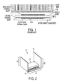
FIGURE 1 , a typical electronics package for a 3D IC is shown. As can be seen, the electronics package relies upon a passive heat sink for thermal management. - Most approaches for electronics gaseous working fluid thermal management are focused on back-side thermal management. An example of such an approach is described in
U.S. Patent Application Publication No. 2005/0280162 to Mok et al. which describes an integrated vapor chamber thermal interposer on the backside of an IC. However, increasingly, 3D architectures (e.g., with heat fluxes approaching 100 watts per square centimeter (W/cm2)) have made this approach insufficient. - 3D die stacks have severe problems with hotspots on each of the layers. Spreading this heat is a major challenge since the typical combination of solder balls, (relatively) low thermal conductivity filler and copper-filled through silicon vias (TSVs) does not provide a sufficiently conductive thermal path. Further, spreading the heat only partially solves the problem as the heat still needs to be dissipated to the environment.
- One proposed solution is described in
U.S. Patent Application Publication No. 2010/0044856 to SRI-JAYANTHA et al. SRI-JAYANTHA et al. modifies the active side or lateral thermal path to improve heat transfer away from the 3D IC using an integrated thermal interposer that utilizes either an additional spreader layer on the backside or a very complex micro channel cooler. This former realization demonstrates fairly modest thermal improvement, while the latter entails considerable complexity in terms of fluidic sealing and pumping. - Another proposed solution is to use thermoelectric thermal bump, examples of which are shown in
FIGURE 1 . However, thermoelectric thermal bumps suffer from the typical shortcomings of thermoelectric materials: poor efficiency and high cost. - Yet another proposed solution is thin film evaporation. It uses a phase change process such as boiling, but mitigates some of the well-known shortcomings of boiling. Specifically, thin film evaporation mitigates the amount of superheat required to initiate boiling, the unpredictability of boiling nucleation sites, handling of combined vapor-liquid flow after boiling (in a flow system) and the critical heat flux (CHF) in which the hot surface dries out if the heat flux is too high.
- The foregoing is described in Ohadi et al., "Ultra - Thin Film Evaporation (UTF) - Application to Emerging Technologies in Cooling of Microelectronics", Microscale Heat Transfer Fundametals and Applications, pages 321-338 (2005):
- Ultra Thin Film (UTF) evaporation is perhaps one of the most effective methods of heat removal from a high heat flux surface for several reasons:
- 1. a small quantity of fluid is required to remove the heat by evaporation at the surface of the thin layer of fluid,
- 2. a very high heat transfer coefficient results from the minimized thermal resistance across the thin liquid layer,
- 3. the surface experiences a very small temperature rise above the saturation temperature of the working fluid, as long as a sufficient quantity of fluid is provided to wet the surface,
- 4. a minimum amount of energy is required to circulate the working fluid due to no pressure drop across the thin film evaporator,
- 5. unlike nucleation boiling where a complex set of parameters determine the stability of the system, UTF is virtually conduction across a very thin film,
- 6. the upper limit on cooling performance would be limited by the homogeneous nucleation temperature and/or kinetics of vapor formation at a free interface, rather than the relatively low CHF.
- The second reason can be clarified using the relationship between heat transferred, thermal resistance and temperature drop, and the definition of the heat transfer coefficient. The heat transfer coefficient R can be defined by Q*R = DT, where Q is heat transferred in watts (W), R is in degrees Celsius per watt (C/W) and DT is temperature drop in degrees Celsius (C). A high thermal resistance means less heat is transferred and there is a large temperature gradient across the material of interest. The thermal resistance and heat transfer coefficient R are related by the relationship R = L/(kA) for conduction, where L is the conduction path length, A is the heat transfer area, and k is the thermal conductivity.
- Additional heat dissipation due to evaporation is what makes thin film evaporation particularly compelling. The amount of heat Q that can be removed at the vapor-liquid interface is Q = m(ΔHv), where m is the mass flow of evaporating liquid and (ΔHv) is the latent heat of vaporization of the refrigerant. Taking a 2 centimeter (cm) X 2 cm die, as typical of integrated circuit packages, and a thermal density of 25 W/cm2, the heat to transfer is 100 W. Using water as a heat transfer fluid, the latent heat is 2260 joules per gram (J/g), so the amount of mass flux is 25/2260 = 0.01 grams per second (g/s) or 10 microliters per second (µL/s) of fluid must be evaporated to dissipate this much heat.
- In view of this, it is clear that large heat transfer area A and small conduction path length L provide a small conduction resistance through the thin film, which increases the amount of heat transferred to the phase change interface. A challenge in thin film evaporator design is feeding the thin film with enough material to match the evaporation rate for high heat fluxes. One solution is to employ electrohydrodynamics (EHD) polarization pumping to draw a thin film of dielectric liquid along a hot surface. However, this solution suffers from orientation dependence and the resulting film is not especially thin. Even so, this solution has been shown to be able to transfer heat fluxes of up to 40 W/cm2.
- It is well-known in the heat pipe community that a significant fraction of heat transfer in the evaporator section of heat pipes occurs in the thin film region where conductive losses are low and evaporation rates are highest. As such, there has been significant work on using wicking structures to maximize the thin film region. A realization of such work combines the application of an actively pumped microchannel cooler with a porous membrane for evaporation. The evaporation rate is augmented with air jet impingement to further improve the heat transfer. This realization demonstrates the ability to dissipate a heat flux of 500 W/cm2. However, this realization requires external infrastructure for pumping and a relatively large thin film. Roughly 85% of the heat transfer is due to the forced convection in the microchannel.
- The present application provides new and improved methods and systems which overcome the above-referenced challenges.
- In accordance with one aspect of the present application, a heat dissipation device to provide thermal spreading and cooling for a heat-producing body is provided. A thin film evaporator in thermal communication with the heat-producing body removes heat from the heat-producing body using a working fluid. A heat pipe integrated with the thin film evaporator, and extending from the thin film evaporator, dissipates heat removed by the thin film evaporator to the external environment of the heat dissipation device. A pumping element at least one of: 1) pumps working fluid to the thin film evaporator; and 2) augments transfer of working fluid to the thin film evaporator.
- In accordance with another aspect of the present application, a heat dissipation method to provide thermal spreading and cooling for a heat-producing body is provided. By a thin film evaporator in thermal communication with the heat-producing body, heat from the heat-producing body is removed using a working fluid. By a heat pipe integrated with the thin film evaporator and extending from the thin film evaporator, heat removed by the thin film evaporator is dissipated to the external environment of the heat dissipation device. By a pumping element, at least one of: 1) working fluid is pumped to the thin film evaporator; and 2) transfer of working fluid to the thin film evaporator is augmented.
- In accordance with another aspect of the present application, a heat dissipation device to provide thermal spreading and cooling for a heat-producing body is provided. A sealed housing includes a fluid reservoir of working fluid in liquid phase and a vapor chamber, the heat-producing body thermally coupled to an external surface of the sealed housing. A thin film evaporator is within the sealed housing and in thermal communication with an internal surface of the sealed housing adjacent the external surface. The thin film evaporator receives working fluid in liquid phase from the fluid reservoir and vaporizes the received working fluid to working fluid in gaseous phase using heat from the heat-producing device. A heat pipe within the sealed housing transfers the working fluid in gaseous phase away from the thin film evaporator, condenses the working fluid in gaseous phase to liquid phase, and returning the condensed working fluid to the fluid reservoir. A pumping element at least one of: 1) pumps working fluid to the thin film evaporator; and 2) augments transfer of working fluid to the thin film evaporator.
-
-
FIGURE 1 illustrates an electronics package relying on passive cooling; -
FIGURE 2 illustrates an embodiment of a heat dissipation device according to aspects of the present application; -
FIGURE 3A illustrates a cross sectional view of the heat dissipation device ofFIGURE 2 ; -
FIGURE 3B illustrates an alternative cross sectional view of the heat dissipation device ofFIGURE 2 ; -
FIGURE 4 illustrates a return wick according to aspects of the present application; and -
FIGURE 5 illustrates another embodiment of a heat dissipation device according to aspects of the present application. -
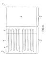
FIGURE 6 illustrates another embodiment of a heat dissipation device using pulsating heat pipe technology according to aspects of the present application. -
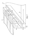
FIGURE 7 illustrates another view of the heat dissipation device according toFIGURE 6 . - This present application combines an actively driven thin film evaporator for spreading heat with an integrated planar heat pipe extended surface for heat sinking. The thin film evaporator allows for a high rate of heat removal to remove hot spots, and the integrated planar heat pipe transports heat from the thin film evaporator to an extended surface for dissipation to the environment or sinking to an interposer layer.
- With reference to
FIGURE 2 , a perspective view of aheat dissipation device 10 of the present application is provided. Theheat dissipation device 10 provides thermal spreading and cooling to an associated heat-producingbody 12, such as an integrated circuit (IC) package (illustrated). Typically, but not necessarily, the IC package is three-dimensional (3D). As will be seen, theheat dissipation device 10 is capable of managing heat fluxes of 10 to 1000 Watts per square centimeter (W/cm2) or more, such as 100 W/cm2. - The
heat dissipation device 10 includes a sealedhousing 14, which is constructed of a thermally conductive material. The thermally conductive material can, for example, include one or more of copper, copper foil, copper alloys, aluminum, aluminum alloys, polyimides, metals, and the like. The sealedhousing 14 can be flexible and seals in a working fluid 16 (FIGURES 3A &B ) for transfer of heat away from the heat-producingdevice 12, as discussed hereafter. Advantageously, when the sealedhousing 14 is flexible, the sealedhousing 14 can be shaped after manufacture when installing theheat dissipation device 10 for the heat-producingbody 12. - An
external surface 18 of aninterface portion 20 of the sealedhousing 14 thermally contacts the heat-producingbody 12. For example, theexternal surface 18 can directly contact the heat-producingbody 12. As another example, theexternal surface 18 can indirectly contact the heat-producingbody 12 by way of a substrate upon which the heat-producingbody 12 rests or a thermal interface material intermediate the heat-producingbody 12 and theexternal surface 18. Typically, theinterface portion 20 is formed from copper, copper foil, copper alloys, aluminum, or aluminum alloys, but other materials are contemplated. - Extending away from the
interface portion 20, the sealedhousing 14 further includes one or more extended portions or fins 22 (two as illustrated). As discussed hereafter, theextended portions 22 are used to convey heat into the external environment, typically by convection, or to sink heat to an interposer layer. Theextended portions 22 are typically formed from a flexible polyimide or metallic substrate to allow theextended portions 22 to be shaped into a desired form factor after manufacture, but other materials are contemplated. - With reference to
FIGURES 3A &3B , within the sealedhousing 14, theheat dissipation device 10 includes avapor chamber 24 and afluid reservoir 26. Thevapor chamber 24 includes aninternal surface 28 of theinterface portion 20 adjacent theexternal portion 18 of theinterface portion 20. Further, thevapor chamber 24 extends into each of theextended portions 22 of the sealedhousing 14, typically to the distal ends 30 of theextended portions 22. Thefluid reservoir 26 is typically disposed in theinterface portion 20 of the sealedhousing 14 central to theextended portions 22. - The
fluid reservoir 26 holds working fluid 16 in the liquid phase (i.e., liquid working fluid 32), and thevapor chamber 24 holds working fluid 16 in the gaseous phase (i.e., gaseous workingfluid 34 shown by the arrows in the vapor chamber 24). The working fluid 16 can include, for example, water, Freon, acetone, alcohol, and the like. As described hereafter, the working fluid 16 is employed to transfer heat away from the heat-producingbody 12 through the sealedhousing 14 using thin film evaporation, where theextended portions 22 act as heat pipes. In this way, heat fluxes of 10 to 1000 Watts per square centimeter (W/cm2) or more can be managed. - The
heat dissipation device 10 includes athin film evaporator 36 for evaporatingliquid working fluid 32 from thefluid reservoir 26 into gaseous workingfluid 34 with heat from the heat-producingbody 12. Typically, thethin film evaporator 36 is actively driven to ensure sufficient transfer of working fluid 16 to cool the heat-producingbody 12, as discussed above, but it can also be passive. For example, thethin film evaporator 36 can be actively driven when the heat-producingbody 12 is producing heat exceeding a predetermined threshold and passively driven when the heat-producingbody 12 is producing heat less than the predetermined threshold. - The
thin film evaporator 36 includes anevaporator wick 38 in thermal contact with theinternal surface 28 of theinterface portion 20 of the sealedhousing 14 and within thevapor chamber 24. Typically, the surface area of theevaporator wick 38 in contact with theinternal surface 28 is approximately (i.e., +/- 5%) equal to, or greater than, the surface area of the heat-producingdevice 12 in contact with theexternal surface 18. Theevaporator wick 38 receivesliquid working fluid 32 from thefluid reservoir 26 and disperses theliquid working fluid 32 substantially uniformly on theinternal surface 28 of theinterface portion 20 of the sealedhousing 14 to form athin layer 40 ofliquid working fluid 32. Suitably, theevaporator wick 38 is engineered to maximize the extent of capillary wicking and the area of thethin layer 40. - The
heat dissipating device 10, particularly the thermal coupling with the heat-producingbody 12, is designed to allow sufficient transfer of heat to thethin layer 40 ofliquid working fluid 32 to cool the heat-producingbody 12. The heat transferred from the heat-producingbody 12 to thethin layer 40 ofliquid working fluid 32 is dictated by the heat transfer coefficient R for conduction, where R = L/(kA), L is the conduction path length, A is the heat transfer area, and k is the thermal conductivity. The greater the heat transfer coefficient R, the less transfer of heat. Hence, the greater the area of thethin layer 40 ofliquid working fluid 32 and the thermal conductivity of the material intermediate the heat-producingbody 12 and thethin layer 40 ofliquid working fluid 32, the greater the heat transfer. Similarly, the less the conduction path length, the greater the heat transfer. - A
feed conduit 42 of the sealedhousing 14 extends between thefluid reservoir 26 and theevaporator wick 38 to provideliquid working fluid 32 to theevaporator wick 38 from thefluid reservoir 26. Theevaporator wick 38 drawsliquid working fluid 32 from thefluid reservoir 26 by way of thefeed conduit 42 using capillary action. This capillary action also serves to disperse theliquid working fluid 32 on theinternal surface 28 of theinterface portion 20 of the sealedhousing 14. The greater the dispersion ofliquid working fluid 32, the greater the transfer of heat from the heat-producingbody 12. Additional feed channels are also contemplated to improve the transfer of liquid workingfluid 32 to theevaporator wick 38. - One or more synthetic jets 44 (two as illustrated) within the sealed
housing 14 can be employed to improve the transfer of liquid workingfluid 32 to gaseous workingfluid 34 by removing gaseous workingfluid 34 from thevapor chamber 24 and cooling theevaporator wick 38 to allow greater dispersion of theliquid working fluid 32 before evaporation. Typically, thesynthetic jets 44 include a plurality of synthetic jets arranged in a grid or other two-dimensional arrangement to cool, and/or remove gaseous workingfluid 34 from, the whole of theevaporator wick 38. Power is provided to thesynthetic jets 44 by way of correspondingwires 46 andpower sources 48. - The
synthetic jets 44 create a series of vortex rings of gaseous workingfluid 34 in thevapor chamber 24 usingcorresponding orifices 50 and corresponding oscillatingactuators 52. The axes of the vortex rings are suitably perpendicular to theinternal surface 28. Suitably, the oscillatingactuators 52 are piezoelectric actuators (illustrated), but other oscillating actuators are contemplated. While any configuration of thesynthetic jets 44 is contemplated, the oscillatingactuators 52 of thesynthetic jets 44 typically oscillate corresponding diaphragms along the axes of the vortex rings. The oscillatingactuators 52 can be the diaphragms (e.g., piezoelectric diaphragms), as illustrated, or merely oscillate the corresponding diaphragms. - The
orifices 50 typically include corresponding open ends 54 through which the vortex rings enter thevapor chamber 24 from theorifices 50. The oscillatingactuators 52 can be, for example, positioned within theorifices 50 to push vapor within theorifices 50 out the open ends 54. Theorifices 50 can further include additional corresponding open ends 56 opposite the open ends 54 through which the vortex rings enter thevapor chamber 24 from theorifices 50. The oscillatingactuators 52 can then be, for example, positioned at the additional open ends 54 to create the vortex rings using, for example, diaphragms spanning the additional open ends 54. - The oscillating
actuators 52 can also be employed to pumpliquid working fluid 32 to theevaporator wick 38 by way of thefeed conduit 42 to ensure that sufficientliquid working fluid 32 is provided to theevaporator wick 38 to prevent dry out of thethin layer 40 ofliquid working fluid 32. Typically, the oscillatingactuators 52 are out of plane (i.e., oscillate perpendicular to the direction flow of the liquid working fluid 32). In such instances, it's important to ensure that theliquid working fluid 32 can only flow in the direction of thefeed conduit 42. Other approaches to pumping theliquid working fluid 32 can also be employed. - One approach to pump
liquid working fluid 32 using the oscillatingactuators 52 is to employ corresponding diaphragms with the oscillatingactuators 52. As noted above, the oscillatingactuators 52 can be the diaphragms (illustrated) or merely oscillate the corresponding diaphragms. In such an approach, the diaphragms partially define the wall of thefluid reservoir 26 and oscillate in and out of thefluid reservoir 26. Typically, the oscillations are perpendicular to thethin film evaporator 36 and the flow of liquid workingfluid 32. As the diaphragms moves in to thefluid reservoir 26, the diaphragms pumpliquid working fluid 32. As the diaphragms move out of thefluid reservoir 26, the diaphragms creates the above described vortex rings. - With specific reference to
FIGURE 3B , in addition to, or as an alternative to, using thefeed conduit 42 to provideliquid working fluid 32 to theevaporator wick 38, thesynthetic jets 44 can sprayliquid working fluid 32 from thefluid reservoir 26, or some other fluid, on to theevaporator wick 38 substantially uniformly. As illustrated inFIGURE 3B , thesynthetic jets 44 receiveliquid working fluid 32 from corresponding feed wicks orconduits 58, which control the flow of liquid workingfluid 32 from thefluid reservoir 26 to theorifices 50. This can help to disperse theliquid working fluid 32 on theinternal surface 28 of theinterface portion 20 of the sealedhousing 14 to form thethin layer 40 ofliquid working fluid 32. - While the
thin film evaporator 36 employs theevaporator wick 38 for receiving and dispersing theliquid working fluid 32, other approaches for receiving and dispersing theliquid working fluid 32 can be employed. For example, a wickless approach or an electrohydrodynamics (EHD) polarization pumping in conjunction with an electrically conductive wick can be employed. As another example, thesynthetic jets 44 can spray theliquid working fluid 32, as described above, on to theinternal surface 28 to create thethin layer 40 ofliquid working fluid 32 without theevaporator wick 38. As another example, thethin film evaporator 36 can work without thesynthetic jets 44, but optionally with the oscillatingactuators 52 pumpingliquid working fluid 32 as described above. - The
thin film evaporator 36 and/or thesynthetic jets 44 need to be designed to transfer and disperse a sufficient amount ofliquid working fluid 32 to remove the heat transferred by the heat-producingbody 12 to thethin layer 40 ofliquid working fluid 32. The amount of heat Q that can be removed at thethin layer 40 ofliquid working fluid 32 is Q = m(ΔHv), where m is the flow of evaporatingliquid work fluid 32 and (ΔHv) is the latent heat of vaporization of the working fluid 16. Hence,thin film evaporator 36 and thesynthetic jets 44 are designed around this equation. - As the
thin layer 40 ofliquid working fluid 32 evaporates, the gaseous workingfluid 34 is transported to theextended portions 22, typically to the distal ends 30 of theextended portions 22, by way of thevapor chamber 24. Thesynthetic jets 44 facilitate transport of the gaseous working 34 fluid to theextended portions 22 by pushing the gaseous workingfluid 34 to theextended portions 22. Within theextended portions 22, the gaseous workingfluid 34 dissipates and condenses back intoliquid working fluid 32. - Adjacent the
vapor chamber 24, eachextended portion 22 includes areturn wick 60 at least extending from the corresponding distal ends 30 to thefluid reservoir 26 and typically lining theextended portion 22. Thereturn wicks 60 capture working fluid 16 as it condenses back to liquid and return it to thefluid reservoir 26, typically using capillary action. In this way, theextended portions 22 can be viewed as planar heat pipes. - The design of the
return wicks 60 is important to the successful operation of theheat dissipation device 10. The flow of working fluid 16 through thereturn wicks 60 must be sufficient to complete the working fluid recirculation loop (shown by the arrows). Thereturn wicks 60 are multi-layer wicks with engineered hydrophobic condensation surfaces and a sub-layer of feed channels that return theliquid working fluid 32 to thefluid reservoir 26. With reference toFIGURE 4 , gaseous workingfluid 34 condenses into aball 62 at the apex 64 of one of thefeed channels 66 before flowing into the feed channel for transport back to thefluid reservoir 26. Further, examples of thereturn wicks 60 at different magnifications (corresponding to images A through D) are provided. - Different approaches to returning the
liquid working fluid 32 to thefluid reservoir 26 can also be employed. For example, a wickless approach or an electrohydrodynamics (EHD) polarization pumping in conjunction with an electrically conductive wick can be employed. - The coupling of a heat pipe to a thin film evaporator, as described above, is to be contrasted with conventional thermal packaging arrangement in which the heat sink is connected to a spreader by way of a thermal interface material (See
FIGURE 1 ). Each of these additional layers introduces thermal resistance and increases the potential for hotspots. On the active side, it is even less straightforward to dissipate heat away. The present application rectifies this problem by coupling extended portions or fins into the thermal path. These extended portions can be viewed as planar heat pipes with a conductive wick lining. - With reference to
FIGURE 5 , another embodiment of theheat dissipation device 10 is illustrated.FIGURE 5 shows a cut away of theheat dissipation device 10 with an emphasis on theextended portions 22. Also, theextended portions 22 are not bent upward as done in theFIGURES 2 ,3A and3B . As noted above, theheat dissipation device 10 can be shaped as need be after manufacture. Theheat dissipation device 10 of this embodiment works as described in connection with the embodiment ofFIGURE 2 . Hence, elements paralleling those of the discussion of the embodiment of theheat dissipation device 10 ofFIGURE 2 are labeled the same. - As illustrated, the
evaporator wick 38 receivesliquid working fluid 32 using capillary action and/or thesynthetic jets 44 from thefluid reservoir 26. Using thisliquid working fluid 32, theevaporator wick 38 creates the thin layer 40 (not shown inFIGURE 5 ) ofliquid working fluid 32 on the internal surface 28 (not shown inFIGURE 5 ) of theinterface portion 20 of the sealedhousing 14. The gaseous working fluid 34 (not shown inFIGURE 5 ) generated by evaporation of theliquid working fluid 32 in thethin layer 40 then travels to theextended portions 22 of the sealedhousing 14 by way of thevapor chamber 24. Thesynthetic jets 44 can be employed to move the gaseous workingfluid 34 to theextended portions 22. - Within the
extended portions 22, the gaseous workingfluid 34 cools and condenses back toliquid working fluid 32. Thisliquid working fluid 32 can collect atcorresponding capture reservoirs 68 at the distal ends 30 of theextended portions 22 and/or be collected by thereturn wicks 60. Thereturn wicks 60 returnliquid working fluid 32 collected thereby and/or from thecapture reservoirs 68 to thefluid reservoir 26, typically using capillary action. In this way, the workingfluid 34 follows a fluid recirculation loop, which is shown by the arrows. - In some embodiments, additional or alternative approaches for removing gaseous working fluid from the interface portion can be employed. For example impinging jets can be employed. Further, in some embodiments, additional or alternative approaches to spreading heat in the
extended portions 22 can be employed. For example, although less efficient than the preferred realization, theextended portions 22 can include pulsating heat pipes (PHPs). Such embodiments employing pulsating heat pipes would be limited by the conduction contact area between the PHPs and the vapor chamber. - With reference to
FIGURES 6 and7 , another embodiment of theheat dissipation device 10 employing PHP technology, which is known in the art, is illustrated. For ease of illustration, only a singleextended portion 22 or fin is described and it's is not bent upward as done in theFIGURES 2 ,3A and3B . However, as noted above, theheat dissipation device 10 can be shaped as need be after manufacture. But for the use of PHP technology, theheat dissipation device 10 of this embodiment works as described in connection with the embodiment ofFIGURE 2 . Hence, elements paralleling those of the discussion of the embodiment of theheat dissipation device 10 ofFIGURE 2 are labeled the same. - Referring to
FIGURE 6 , a top view of theheat dissipation device 10 is illustrated. Of note, all the detail of theinterface portion 20 is not shown. Each of theextended portions 22 includes one or more PHPs 80 and aheat exchanger 82. Alternatively, theextended portions 22 can share a common PHP. Theheat exchangers 82 are typically positioned proximate theinterface portion 20 at the bases of the correspondingextended portions 22. Further, thePHPs 80 typically extend from the distal ends 30 of the correspondingextended portions 22 in to thecorresponding heat exchangers 82. - The
heat exchangers 82 receivegaseous working fluid 34 from thevapor chamber 24. Within theheat exchangers 82, the heat from the gaseous workingfluid 34 is absorbed by thePHPs 80, which transfer the absorbed heat to the distal ends 30 of theextended portions 22 for dissipation to the external environment. As the heat is absorbed by thePHPs 80, the gaseous workingfluid 34 condenses back toliquid working fluid 32 and is returned to thefluid reservoir 26. - With reference to
FIGURE 7 , a partial, perspective view of theheat exchangers 82 is illustrated. Each of theheat exchangers 82 includes acapture reservoir 84 in which condensed workingfluid 32 collects. Thecapture reservoirs 84 are typically positioned under the portions of thePHPs 80 extending into theheat exchangers 82. Further, notwithstanding the orientation of thePHPs 80, those skilled in the art will appreciate that other orientations are amenable. - "Drop-wise condensation" is generally desired since it gives higher heat fluxes. This is encouraged by coating and/or encapsulating the portions of the
PHPs 80 extending into theheat exchangers 82 withhydrophobic material 86. For example, a thin layer of Polytetrafluoroethylene (PTFE), such as that found on a nonstick cooking pan, can coat these portions of thePHPs 80. As illustrated, thePHPs 80 are encapsulated inhydrophobic material 86 and causedroplets 88 ofliquid working fluid 32 to form and fall into thecapture reservoirs 82. - To return the condensed working
fluid 32 to thefluid reservoir 26, each of theextended portions 22 includes areturn wick 90 extending from thecorresponding capture reservoir 84 to thefluid reservoir 26. Thereturn wick 90 uses capillary action as described above to transfer theliquid working fluid 32 in the captured. - It will be understood that features disclosed in association with particular embodiments are intended to be interchangeable with other embodiments unless the context would prevent it.
Claims (15)
- A heat dissipation device to provide thermal spreading and cooling for a heat-producing body, said heat dissipation device comprising:a thin film evaporator in thermal communication with the heat-producing body to remove heat from the heat-producing body using a working fluid;a heat pipe integrated with the thin film evaporator, and extending from the thin film evaporator, to dissipate heat removed by the thin film evaporator to the external environment of the heat dissipation device; anda pumping element to at least one of: 1) pump working fluid to the thin film evaporator; and 2) augment transfer of working fluid to the thin film evaporator.
- The heat dissipation device according to claim 1, wherein the pumping element includes an oscillating actuator at least one of: 1) pumping working fluid to the thin film evaporator; and 2) augmenting transfer of working fluid to the thin film evaporator; and wherein, optionally, the oscillating actuator is a piezoelectric oscillator.
- The heat dissipation device according to claim 1 or claim 2, wherein the pumping element is integrated in a sealed housing with the thin film evaporator and the heat pipe.
- The heat dissipation device according to any of the preceding claims, wherein the pumping element includes a synthetic jet augmenting transfer of working fluid to the thin film evaporator.
- The heat dissipation device according to any of the preceding claims, wherein the heat pipe is at least one of an integrated planar heat pipe or a pulsating heat pipe.
- The heat dissipation device according to any of the preceding claims, wherein the thin film evaporator receives working fluid in liquid phase from a fluid reservoir and transfers the received working fluid in liquid phase to gaseous phase using heat from the heat-producing body, and wherein the heat pipe cools and condenses the working fluid in gaseous phase to working fluid in liquid phase and returns the condensed working fluid in liquid phase to the fluid reservoir.
- The heat dissipation device according to claim 6, wherein the heat pipe returns the condensed working fluid in liquid phase to the fluid reservoir using a return wick.
- The heat dissipation device according to claim 6 or claim 7, wherein the thin film evaporator includes an evaporator wick to create a thin film transferring the received working fluid in liquid phase to the gaseous phase.
- The heat dissipation device according to any of claims 6 to 8, further including:a second heat pipe integrated with the thin film evaporator, and extending from the thin film evaporator, to dissipate heat removed by the thin film evaporator to the external environment of the heat dissipation device, wherein the fluid reservoir is central to the heat pipe and the second heat pipe.
- The heat dissipation device according to any of claims 6 to 9, wherein working fluid in gaseous phase is transferred to the heat pipe using a vapor chamber, the vapor chamber including the thin film evaporator.
- The heat dissipation device according to any of the preceding claims, wherein the heat dissipating device includes:a sealed housing including:a fluid reservoir for working fluid in liquid phase; anda vapor chamber extending from the thin film evaporator to the heat pipe;wherein the thin film evaporator receives working fluid in liquid phase from the fluid reservoir and vaporizes the received working fluid in liquid phase to working fluid in gaseous phase, the working fluid in gaseous phase transferred to the heat pipe by way of the vapor chamber.
- A heat dissipation method to provide thermal spreading and cooling for a heat-producing body, said heat dissipation method comprising:by a thin film evaporator in thermal communication with the heat-producing body, removing heat from the heat-producing body using a working fluid;by a heat pipe integrated with the thin film evaporator and extending from the thin film evaporator, dissipating heat removed by the thin film evaporator to the external environment of the heat dissipation device; andby a pumping element, at least one of: 1) pumping working fluid to the thin film evaporator; and 2) augmenting transfer of working fluid to the thin film evaporator.
- The heat dissipation method according to claim 12, further including:by an oscillating actuator of the pumping element, at least one of: 1) pumping working fluid to the thin film evaporator; and 2) augmenting transfer of working fluid to the thin film evaporator.
- The heat dissipation device according to claim 12 or claim 13, further including:by the thin film evaporator:receiving working fluid in liquid phase from a fluid reservoir; andtransferring the received working fluid in liquid phase to gaseous phase using heat from the heat-producing body; andby the heat pipe:cooling and condensing the working fluid in gaseous phase to working fluid in liquid phase; andreturning the condensed working fluid in liquid phase to the fluid reservoir.
- A heat dissipation device to provide thermal spreading and cooling for a heat-producing body according to any of claims 1 to 11, said heat dissipation device comprising:a sealed housing including a fluid reservoir of working fluid in liquid phase and a vapor chamber, the heat-producing body thermally coupled to an external surface of the sealed housing;wherein the thin film evaporator is positioned within the sealed housing and in thermal communication with an internal surface of the sealed housing adjacent the external surface, the thin film evaporator receiving working fluid in liquid phase from the fluid reservoir and vaporizing the received working fluid to working fluid in gaseous phase using heat from the heat-producing device; and,wherein the heat pipe is positioned within the sealed housing for transferring the working fluid in gaseous phase away from the thin film evaporator, condensing the working fluid in gaseous phase to liquid phase, and returning the condensed working fluid to the fluid reservoir.
Applications Claiming Priority (1)
| Application Number | Priority Date | Filing Date | Title |
|---|---|---|---|
| US13/746,453 US20140202665A1 (en) | 2013-01-22 | 2013-01-22 | Integrated thin film evaporation thermal spreader and planar heat pipe heat sink |
Publications (2)
| Publication Number | Publication Date |
|---|---|
| EP2757584A2 true EP2757584A2 (en) | 2014-07-23 |
| EP2757584A3 EP2757584A3 (en) | 2015-11-04 |
Family
ID=50000804
Family Applications (1)
| Application Number | Title | Priority Date | Filing Date |
|---|---|---|---|
| EP14152200.3A Withdrawn EP2757584A3 (en) | 2013-01-22 | 2014-01-22 | Integrated thin film evaporation thermal spreader and planar heat pipe heat sink |
Country Status (4)
| Country | Link |
|---|---|
| US (1) | US20140202665A1 (en) |
| EP (1) | EP2757584A3 (en) |
| JP (1) | JP2014143417A (en) |
| CN (1) | CN103943576A (en) |
Cited By (3)
| Publication number | Priority date | Publication date | Assignee | Title |
|---|---|---|---|---|
| EP3016139A1 (en) * | 2014-10-28 | 2016-05-04 | Goodrich Corporation | Planar heat cup with confined reservoir for electronic power component |
| EP3963625B1 (en) * | 2019-04-29 | 2025-01-29 | Qualcomm Incorporated | Multi-phase heat dissipating device comprising piezo structures |
| CN119634074A (en) * | 2024-11-22 | 2025-03-18 | 华南理工大学 | A cascade fluid oscillation jet device for chip heat dissipation |
Families Citing this family (13)
| Publication number | Priority date | Publication date | Assignee | Title |
|---|---|---|---|---|
| US10356945B2 (en) * | 2015-01-08 | 2019-07-16 | General Electric Company | System and method for thermal management using vapor chamber |
| US10103311B2 (en) | 2015-07-17 | 2018-10-16 | Marlow Industries, Inc. | Flexible sink for a thermoelectric energy generation system |
| US9750160B2 (en) | 2016-01-20 | 2017-08-29 | Raytheon Company | Multi-level oscillating heat pipe implementation in an electronic circuit card module |
| US10267568B2 (en) * | 2016-05-11 | 2019-04-23 | Toyota Motor Engineering & Manufacturing North America, Inc. | Programmable ultrasonic thermal diodes |
| US10209009B2 (en) | 2016-06-21 | 2019-02-19 | General Electric Company | Heat exchanger including passageways |
| CN106061201A (en) * | 2016-06-23 | 2016-10-26 | 联想(北京)有限公司 | Cooling device and electronic equipment |
| US10453768B2 (en) | 2017-06-13 | 2019-10-22 | Microsoft Technology Licensing, Llc | Thermal management devices and systems without a separate wicking structure and methods of manufacture and use |
| CN109817803A (en) * | 2017-11-20 | 2019-05-28 | 博士门股份有限公司 | Refrigeration chip device with high heat exchange rate |
| US20190191589A1 (en) * | 2017-12-15 | 2019-06-20 | Google Llc | Three-Dimensional Electronic Structure with Integrated Phase-Change Cooling |
| JP6588599B1 (en) * | 2018-05-29 | 2019-10-09 | 古河電気工業株式会社 | Vapor chamber |
| CN113466080B (en) * | 2021-07-09 | 2023-03-21 | 上海紫华薄膜科技有限公司 | Batch evaporation rate testing device |
| US12324128B2 (en) * | 2021-10-28 | 2025-06-03 | Worcester Polytechnic Institute | Gravity independent liquid cooling for electronics |
| US12439556B2 (en) * | 2021-12-20 | 2025-10-07 | Frore Systems Inc. | MEMS-based system for cooling a vapor chamber |
Citations (2)
| Publication number | Priority date | Publication date | Assignee | Title |
|---|---|---|---|---|
| US20050280162A1 (en) | 2004-06-18 | 2005-12-22 | International Business Machines Corporation | Thermal interposer for thermal management of semiconductor devices |
| US20100044856A1 (en) | 2008-08-19 | 2010-02-25 | International Business Machines Corporation | Electronic package with a thermal interposer and method of manufacturing the same |
Family Cites Families (9)
| Publication number | Priority date | Publication date | Assignee | Title |
|---|---|---|---|---|
| US5943211A (en) * | 1997-04-18 | 1999-08-24 | Raytheon Company | Heat spreader system for cooling heat generating components |
| US6410982B1 (en) * | 1999-11-12 | 2002-06-25 | Intel Corporation | Heatpipesink having integrated heat pipe and heat sink |
| US6889756B1 (en) * | 2004-04-06 | 2005-05-10 | Epos Inc. | High efficiency isothermal heat sink |
| US20050284612A1 (en) * | 2004-06-22 | 2005-12-29 | Machiroutu Sridhar V | Piezo pumped heat pipe |
| US7265979B2 (en) * | 2004-06-24 | 2007-09-04 | Intel Corporation | Cooling integrated circuits using a cold plate with two phase thin film evaporation |
| US20060090882A1 (en) * | 2004-10-28 | 2006-05-04 | Ioan Sauciuc | Thin film evaporation heat dissipation device that prevents bubble formation |
| US20070023169A1 (en) * | 2005-07-29 | 2007-02-01 | Innovative Fluidics, Inc. | Synthetic jet ejector for augmentation of pumped liquid loop cooling and enhancement of pool and flow boiling |
| US8069907B2 (en) * | 2007-09-13 | 2011-12-06 | 3M Innovative Properties Company | Flexible heat pipe |
| US7980078B2 (en) * | 2008-03-31 | 2011-07-19 | Mccutchen Co. | Vapor vortex heat sink |
-
2013
- 2013-01-22 US US13/746,453 patent/US20140202665A1/en not_active Abandoned
-
2014
- 2014-01-14 JP JP2014004230A patent/JP2014143417A/en not_active Withdrawn
- 2014-01-16 CN CN201410020047.4A patent/CN103943576A/en active Pending
- 2014-01-22 EP EP14152200.3A patent/EP2757584A3/en not_active Withdrawn
Patent Citations (2)
| Publication number | Priority date | Publication date | Assignee | Title |
|---|---|---|---|---|
| US20050280162A1 (en) | 2004-06-18 | 2005-12-22 | International Business Machines Corporation | Thermal interposer for thermal management of semiconductor devices |
| US20100044856A1 (en) | 2008-08-19 | 2010-02-25 | International Business Machines Corporation | Electronic package with a thermal interposer and method of manufacturing the same |
Non-Patent Citations (1)
| Title |
|---|
| OHADI ET AL.: "Ultra - Thin Film Evaporation (UTF) - Application to Emerging Technologies in Cooling of Microelectronics", MICROSCALE HEAT TRANSFER FUNDAMETALS AND APPLICATIONS, 2005, pages 321 - 338 |
Cited By (4)
| Publication number | Priority date | Publication date | Assignee | Title |
|---|---|---|---|---|
| EP3016139A1 (en) * | 2014-10-28 | 2016-05-04 | Goodrich Corporation | Planar heat cup with confined reservoir for electronic power component |
| US9723753B2 (en) | 2014-10-28 | 2017-08-01 | Hamilton Sundstrand Corporation | Planar heat cup with confined reservoir for electronic power component |
| EP3963625B1 (en) * | 2019-04-29 | 2025-01-29 | Qualcomm Incorporated | Multi-phase heat dissipating device comprising piezo structures |
| CN119634074A (en) * | 2024-11-22 | 2025-03-18 | 华南理工大学 | A cascade fluid oscillation jet device for chip heat dissipation |
Also Published As
| Publication number | Publication date |
|---|---|
| EP2757584A3 (en) | 2015-11-04 |
| JP2014143417A (en) | 2014-08-07 |
| US20140202665A1 (en) | 2014-07-24 |
| CN103943576A (en) | 2014-07-23 |
Similar Documents
| Publication | Publication Date | Title |
|---|---|---|
| US20140202665A1 (en) | Integrated thin film evaporation thermal spreader and planar heat pipe heat sink | |
| US11201102B2 (en) | Module lid with embedded two-phase cooling and insulating layer | |
| US7434308B2 (en) | Cooling of substrate using interposer channels | |
| US6785134B2 (en) | Embedded liquid pump and microchannel cooling system | |
| US7002247B2 (en) | Thermal interposer for thermal management of semiconductor devices | |
| JP3651790B2 (en) | High density chip mounting equipment | |
| EP2313937B1 (en) | Stacked thermoelectric modules | |
| US20080115916A1 (en) | Cooling device for an electronic component | |
| US20070258213A1 (en) | Apparatuses for dissipating heat from semiconductor devices | |
| US20130020053A1 (en) | Low-profile heat-spreading liquid chamber using boiling | |
| KR20040051517A (en) | Heat Transfer Device and Electro Device | |
| WO2014157147A1 (en) | Cooling apparatus | |
| CN110192273A (en) | Method and apparatus for spreading high heat flux in a thermal ground plane | |
| JP2012043954A (en) | Semiconductor device | |
| Hota et al. | Performance investigation on different form factor embedded heat pipe and pulsating heat pipe heat spreaders | |
| US7584622B2 (en) | Localized refrigerator apparatus for a thermal management device | |
| JP5485450B1 (en) | Heat spreader | |
| JP2006242455A (en) | Cooling method and apparatus | |
| JP2008218513A (en) | Cooling system | |
| JP2014120516A (en) | Semiconductor device | |
| Kim et al. | Modeling, design and demonstration of ultra-miniaturized glass PA modules with efficient thermal dissipation | |
| JP5682409B2 (en) | Loop heat pipe and electronic device | |
| Jung et al. | Thermal Management Research–from Power Electronics to Portables | |
| JP2008108781A (en) | Cooling system | |
| Shooshtari et al. | Electronics, Next Generation: Cooling of |
Legal Events
| Date | Code | Title | Description |
|---|---|---|---|
| PUAI | Public reference made under article 153(3) epc to a published international application that has entered the european phase |
Free format text: ORIGINAL CODE: 0009012 |
|
| 17P | Request for examination filed |
Effective date: 20140122 |
|
| AK | Designated contracting states |
Kind code of ref document: A2 Designated state(s): AL AT BE BG CH CY CZ DE DK EE ES FI FR GB GR HR HU IE IS IT LI LT LU LV MC MK MT NL NO PL PT RO RS SE SI SK SM TR |
|
| AX | Request for extension of the european patent |
Extension state: BA ME |
|
| PUAL | Search report despatched |
Free format text: ORIGINAL CODE: 0009013 |
|
| AK | Designated contracting states |
Kind code of ref document: A3 Designated state(s): AL AT BE BG CH CY CZ DE DK EE ES FI FR GB GR HR HU IE IS IT LI LT LU LV MC MK MT NL NO PL PT RO RS SE SI SK SM TR |
|
| AX | Request for extension of the european patent |
Extension state: BA ME |
|
| RIC1 | Information provided on ipc code assigned before grant |
Ipc: H01L 23/427 20060101AFI20151001BHEP Ipc: H01L 23/473 20060101ALI20151001BHEP |
|
| R17P | Request for examination filed (corrected) |
Effective date: 20160504 |
|
| RBV | Designated contracting states (corrected) |
Designated state(s): AL AT BE BG CH CY CZ DE DK EE ES FI FR GB GR HR HU IE IS IT LI LT LU LV MC MK MT NL NO PL PT RO RS SE SI SK SM TR |
|
| STAA | Information on the status of an ep patent application or granted ep patent |
Free format text: STATUS: THE APPLICATION IS DEEMED TO BE WITHDRAWN |
|
| 18D | Application deemed to be withdrawn |
Effective date: 20180801 |