EP2757572A1 - Sample heating holder for electron beam microscopes or analyzers, and sample heating method using the same - Google Patents
Sample heating holder for electron beam microscopes or analyzers, and sample heating method using the same Download PDFInfo
- Publication number
- EP2757572A1 EP2757572A1 EP12831362.4A EP12831362A EP2757572A1 EP 2757572 A1 EP2757572 A1 EP 2757572A1 EP 12831362 A EP12831362 A EP 12831362A EP 2757572 A1 EP2757572 A1 EP 2757572A1
- Authority
- EP
- European Patent Office
- Prior art keywords
- sample
- heating
- holder
- electron beam
- sample heating
- Prior art date
- Legal status (The legal status is an assumption and is not a legal conclusion. Google has not performed a legal analysis and makes no representation as to the accuracy of the status listed.)
- Granted
Links
Images

Classifications
-
- H—ELECTRICITY
- H01—ELECTRIC ELEMENTS
- H01J—ELECTRIC DISCHARGE TUBES OR DISCHARGE LAMPS
- H01J37/00—Discharge tubes with provision for introducing objects or material to be exposed to the discharge, e.g. for the purpose of examination or processing thereof
- H01J37/02—Details
- H01J37/20—Means for supporting or positioning the object or the material; Means for adjusting diaphragms or lenses associated with the support
-
- H—ELECTRICITY
- H01—ELECTRIC ELEMENTS
- H01J—ELECTRIC DISCHARGE TUBES OR DISCHARGE LAMPS
- H01J2237/00—Discharge tubes exposing object to beam, e.g. for analysis treatment, etching, imaging
- H01J2237/02—Details
- H01J2237/022—Avoiding or removing foreign or contaminating particles, debris or deposits on sample or tube
-
- H—ELECTRICITY
- H01—ELECTRIC ELEMENTS
- H01J—ELECTRIC DISCHARGE TUBES OR DISCHARGE LAMPS
- H01J2237/00—Discharge tubes exposing object to beam, e.g. for analysis treatment, etching, imaging
- H01J2237/20—Positioning, supporting, modifying or maintaining the physical state of objects being observed or treated
- H01J2237/2001—Maintaining constant desired temperature
Definitions
- the present invention relates to a sample heating holder for electron beam microscopes or analyzers such as electron microscopes and electron beam microanalyzers, and to a sample heating method using the same.
- Electron beam microscopes or analyzers such as scanning electron microscopes, transmission electron microscopes, electron beam microanalyzers and Auger electron spectrometers are utilized in microstructural evaluation of materials.
- Such instruments have a serious problem in that the contrast of images is changed or the accuracy of the analysis of elements such as carbon is lowered due to the occurrence of carbon contaminations (hereinafter, "contaminants") on the sample surface by the interaction of the incident electron beam with pollutants such as hydrocarbons present on or in the vicinity of the surface of the evaluation samples.
- the pollutants find their way mainly through four routes: samples, sample holders, vacuum evacuation systems, and inner parts of the devices.
- the entry of the pollutants through vacuum evacuation systems can be suppressed to a degree by, for example, purging the sample chamber with nitrogen gas, or the use of liquid nitrogen traps or oil-free vacuum pumps.
- the pollutants Once the pollutants are brought to the inside of the sample chamber, they are attached or adsorbed to surfaces such as sample chamber walls or a sample holder and become resistant to removal even by high vacuum evacuation. Further, a sample, no matter how clean it is, is contaminated when exposed to air by the adsorption of carbon sources such as hydrocarbons to its surface. Inappropriate pretreatments, handling and storage of samples result in an increase in the amounts of pollutants brought by the samples to the sample chamber.
- an effective anti-contaminant measure is to remove as much pollutants as possible from the vicinity of a sample or to immobilize the pollutants before the sample is observed and analyzed by the application of electron beam.
- Liquid nitrogen traps are the most popular method for removing pollutants present on or in the vicinity of the sample surface.
- a cold fin cooled by liquid nitrogen is provided in the vicinity of the sample, and pollutant molecules which have arrived at the fin via gas-phase diffusion and surface diffusion are temporarily trapped. This method cannot remove all the pollutants around the sample, and thus the occurrence of contaminants cannot be prevented perfectly.
- ultrahigh-vacuum evacuation of the sample chamber entails baking operations in which the surrounding of the sample chamber is heated at 100 to 200°C for several hours to several days. This incurs many device restrictions such as that the materials and the analytical spectrometer and electron gun used in the device have to be designed to withstand the baking operations as well as the continuous application of ultrahigh vacuum. Further, because this method does not directly remove pollutants present on the sample surface, the formation of contaminants cannot be suppressed perfectly by this method alone.
- sputtering with ions such as Ar ions is applicable only to devices which permit mounting of a sputtering ion gun.
- this method involves the destruction of the sample surface, its application is limited to cases in which image observation and elementary analysis of the sample surface are not adversely affected by sputtering.
- this method has to be used in combination with ultrahigh vacuum evacuation of the sample chamber in order to perfectly prevent the growth of contaminants because otherwise pollutant molecules are adsorbed again to the sample surface which has been cleaned by sputtering.
- Non Patent Literature 1 and references cited therein propose a technique in which pollutants are removed by applying a low-energy high-frequency reactive gas plasma to a sample and a sample holder. Further, Patent Literatures 1 to 3 propose methods and devices in which an oxygen-containing gas such as air is ionized into a high-frequency plasma producing oxygen radicals, which are applied to the sample surface and its surrounding to oxidize pollutants and convert them into easily removed gases such as H 2 O, CO and CO 2 .
- an oxygen-containing gas such as air is ionized into a high-frequency plasma producing oxygen radicals
- Non Patent Literature 1 and Patent Literatures 1 to 3 cannot perfectly remove pollutants probably because the plasma or the radicals are not sufficiently applied to the sample and its surrounding, thus failing to prevent stably the occurrence of contaminants on the sample surface.
- the present inventors carried out extensive studies in order to achieve the above object and have found the following as a result.
- the present invention has been made based on the above findings.
- the invention provides a sample heating holder for an electron beam microscope or analyzer which includes a positive temperature coefficient (PTC) thermistor as a heating element.
- PTC positive temperature coefficient
- the invention also provides a method for heating a sample in an electron beam microscope or analyzer while excellently suppressing the growth of carbon contaminations and the occurrence of a thermal drift during observation and analysis, the method being characterized in that the sample heating holder is used and heat is generated by passing a direct current through the PTC thermistor. In the method, it is preferable that a plasma or oxygen radicals be applied.
- the inventive sample heating holder By the use of the inventive sample heating holder, it becomes possible to prevent stably the growth of contaminants on the sample surface without destructing the sample surface by treatments such as Ar ion sputtering as well as to suppress the occurrence of a thermal drift in the sample in electron beam devices such as electron microscopes and electron beam microanalyzers which are not in ultrahigh vacuum. Thus, image observation and elementary analysis can be performed with high accuracy.
- heating of a sample is effective for preventing the occurrence of contaminants on the sample surface in a high vacuum environment.
- This anti-contaminant effect is obtained at a heating temperature of about 50°C and becomes marked as the temperature is increased.
- an excessively high temperature causes changes in the microstructure or the quality of the sample.
- the heating temperature be set in accordance with the types of samples.
- the heating temperature is preferably about 100°C when inorganic materials or metallic materials are the subjects.
- the present invention uses a PTC thermistor capable of suppressing temperature changes of itself by itself as the heating element, and thereby suppresses the occurrence of a thermal drift in the sample or the sample holder.
- Thermistors are resistors whose electrical resistance varies significantly with temperature
- PTC thermistors are a type of thermistors which increases the electrical resistance with temperature increase. This type of thermistors operates nonlinearly such that the resistance is increased sharply above the Curie temperature. When an electric current is passed therethrough continuously, the thermistors are self-heated and come to allow less current to flow, thereby maintaining a constant temperature. This is how the thermistors function as constant temperature heating elements. In this manner, the PTC thermistors have a self-temperature-regulating function and allow the temperature to be raised rapidly without the occurrence of hunting at the set temperature. Thus, the PTC thermistors serve as highly effective heating elements for the suppression of the occurrence of a thermal drift.
- a ceramic PTC thermistor including barium titanate with additives is a suitable PTC thermistor because this thermistor exhibits thermistor characteristics as a result of the phase transition of barium titanate from the stable tetragonal form at room temperature to the stable cubic form at 120°C or above, as well as because the set temperature (the Curie temperature) can be adjusted in the range from less than 100°C to about 300°C by controlling the amounts of the additives.
- the thermistor be allowed to generate heat by passing a direct current therethrough. If an alternate current is used, an alternate current magnetic field is generated around the current flow channel including the thermistor to cause the applied electron beam to be oscillated, thus resulting in problems such as distorted or blurred electron microscope images and misplaced analysis positions. Consequently, serious problems are encountered in the recording of electron microscope images or the analysis of ultrafine regions particularly at a high magnification where the accurate application of the electron beam is important. On the other hand, the use of a direct current is free from such problems because only a static magnetic field is produced.
- contaminants can be reduced more stably by using a direct current in combination with the application of plasma or oxygen radicals.
- the use of the PTC thermistor eliminates the need for evacuating the device to an ultrahigh vacuum or performing Ar sputtering, and the sample surface is allowed to remain intact.
- An inventive sample heating holder was provided in which a ceramic PTC thermistor having a Curie temperature of 92°C, a service voltage of 100 V and a stable current of 32 mA was immobilized on an existing aluminum sample holder for a scanning electron microscope through a double-sided copper tape (a copper-containing double-sided tape).
- a comparative PID-controllable sample heating holder was provided in which an insulating-coated nichrome wire heater and a thermocouple were immobilized on the similar aluminum sample holder through the copper tape. The following test was performed using these sample heating holders.
- a commercially available specular polished silicon wafer was cleaned with isopropyl alcohol for 10 minutes and was dried in air.
- This wafer as a sample was immobilized to the heating section of the sample heating holder through the double-sided copper tape, and the holder was set onto the sample stage of scanning electron microscope SUPRA 55VP manufactured by Carl Zeiss.
- the amounts of contaminants and the amounts of thermal drift at the set temperatures of room temperature (28°C) and 92°C were measured by the methods described below.
- a direct current voltage was applied via a current inlet terminal mounted on the front side of the SUPRA 55VP sample stage.
- a temperature-controlling microprocessor was connected to the comparative sample heating holder so that the temperature could be PID-controlled at 92°C.
- the scanning electron microscope was operated under the conditions in which accelerating voltage: 5 kV, probe current: 0.1 nA, electron beam illumination time: 500 sec, and observation magnification: x100000. To avoid any influence of charge up, the sample in each sample heating holder was grounded to the aluminum holder through a commercially available conductive Cu tape.
- Amounts of contaminants With use of an energy dispersive X-ray spectrometer mounted on the scanning electron microscope, the amount of contaminants was evaluated based on the integral intensity of the K ⁇ line of carbon (C) on the sample surface (the peak intensity including the background, referred to simply as "integral C intensity) that was integrated during the electron beam illumination time.
- Amounts of thermal drift The amount of thermal drift was evaluated based on the distance of movement of the observation field of view during the electron beam illumination time.
- the amounts of thermal drift (the distances of movement of the field of view) in both cases were as small as 10 nm at room temperature. However, a marked difference was observed between the holders when the temperature was raised to 92°C.
- the inventive sample heating holder had as small a drift as 90 nm, the level permitting tracking of the position of image observation or elementary analysis.
- the drift in the comparative sample heating holder was more than 1000 nm which would make tracking of the position of image observation or elementary analysis infeasible.
- the use of the inventive sample heating holder allows the temperature to be automatically controlled to the target temperature only with the need for a connection to a power source (without a specific temperature-controlling circuit). Accordingly, the sample can be heated in such a manner that the occurrence of contaminants on the sample surface can be prevented and the occurrence of a thermal drift can be suppressed. Thus, image observation and elementary analysis can be performed with high accuracy.
- Sample heating holders Integral C intensities (cps) View field movement distance (nm) 28°C 92°C 28°C 92°C Inventive Example 520 9 10 90 Comparative Example 511 12 10 1350
- pure iron a commercially available plate-shaped standard sample: 99.9% purity
- the amount of contaminants (the integral C intensity) on the sample surface was measured for various durations of electron beam illumination time while performing heating, while performing heating plus the application of oxygen radicals, or while the sample remained untreated without heating.
- the heating was carried out under the similar conditions as in EXAMPLE 1, and the oxygen radicals were applied with a commercial high-frequency plasma generator.
- a commercially available ultralow carbon steel sheet was etched with Nital, then cleaned with alcohol and dried in air.
- This steel sheet as a sample was immobilized to the heating section of the sample heating holder through the double-sided copper tape, and the holder was set onto the sample stage of scanning electron microscope SUPRA 55VP manufactured by Carl Zeiss. Image observation was performed with the temperature set at 92°C. Here, the image observation was made while applying a direct current voltage or an alternate current voltage to the sample heating holder via a current inlet terminal mounted on the front side of the SUPRA 55VP sample stage.
- the scanning electron microscope was operated under the conditions in which accelerating voltage: 5 kV, probe current: 0.1 nA, electron beam illumination time: 500 sec, and observation magnification: x10000.
- the sample in the sample heating holder was grounded to the aluminum holder through a commercially available conductive Cu tape.
Landscapes
- Chemical & Material Sciences (AREA)
- Analytical Chemistry (AREA)
- Analysing Materials By The Use Of Radiation (AREA)
- Sampling And Sample Adjustment (AREA)
Description
- The present invention relates to a sample heating holder for electron beam microscopes or analyzers such as electron microscopes and electron beam microanalyzers, and to a sample heating method using the same.
- Electron beam microscopes or analyzers such as scanning electron microscopes, transmission electron microscopes, electron beam microanalyzers and Auger electron spectrometers are utilized in microstructural evaluation of materials. Such instruments have a serious problem in that the contrast of images is changed or the accuracy of the analysis of elements such as carbon is lowered due to the occurrence of carbon contaminations (hereinafter, "contaminants") on the sample surface by the interaction of the incident electron beam with pollutants such as hydrocarbons present on or in the vicinity of the surface of the evaluation samples.
- The pollutants find their way mainly through four routes: samples, sample holders, vacuum evacuation systems, and inner parts of the devices. The entry of the pollutants through vacuum evacuation systems can be suppressed to a degree by, for example, purging the sample chamber with nitrogen gas, or the use of liquid nitrogen traps or oil-free vacuum pumps. Once the pollutants are brought to the inside of the sample chamber, they are attached or adsorbed to surfaces such as sample chamber walls or a sample holder and become resistant to removal even by high vacuum evacuation. Further, a sample, no matter how clean it is, is contaminated when exposed to air by the adsorption of carbon sources such as hydrocarbons to its surface. Inappropriate pretreatments, handling and storage of samples result in an increase in the amounts of pollutants brought by the samples to the sample chamber.
- The molecules of pollutants brought to the inside of a device move about the device via surface diffusion and gas-phase diffusion. Such pollutant molecules which are moving about are finally aggregated to a sample illumination position as if they are drawn to the electron beam, thus forming contaminants. In view of the fact that contaminants are formed in this process, an effective anti-contaminant measure is to remove as much pollutants as possible from the vicinity of a sample or to immobilize the pollutants before the sample is observed and analyzed by the application of electron beam.
- Liquid nitrogen traps are the most popular method for removing pollutants present on or in the vicinity of the sample surface. In this method, a cold fin cooled by liquid nitrogen is provided in the vicinity of the sample, and pollutant molecules which have arrived at the fin via gas-phase diffusion and surface diffusion are temporarily trapped. This method cannot remove all the pollutants around the sample, and thus the occurrence of contaminants cannot be prevented perfectly.
- Other widely known methods are to evacuate the sample chamber to an ultrahigh degree of vacuum, and to sputter the sample surface with ions such as Ar ions. However, ultrahigh-vacuum evacuation of the sample chamber entails baking operations in which the surrounding of the sample chamber is heated at 100 to 200°C for several hours to several days. This incurs many device restrictions such as that the materials and the analytical spectrometer and electron gun used in the device have to be designed to withstand the baking operations as well as the continuous application of ultrahigh vacuum. Further, because this method does not directly remove pollutants present on the sample surface, the formation of contaminants cannot be suppressed perfectly by this method alone. On the other hand, sputtering with ions such as Ar ions is applicable only to devices which permit mounting of a sputtering ion gun. Further, because this method involves the destruction of the sample surface, its application is limited to cases in which image observation and elementary analysis of the sample surface are not adversely affected by sputtering. Furthermore, this method has to be used in combination with ultrahigh vacuum evacuation of the sample chamber in order to perfectly prevent the growth of contaminants because otherwise pollutant molecules are adsorbed again to the sample surface which has been cleaned by sputtering.
- Non Patent Literature 1 and references cited therein propose a technique in which pollutants are removed by applying a low-energy high-frequency reactive gas plasma to a sample and a sample holder. Further, Patent Literatures 1 to 3 propose methods and devices in which an oxygen-containing gas such as air is ionized into a high-frequency plasma producing oxygen radicals, which are applied to the sample surface and its surrounding to oxidize pollutants and convert them into easily removed gases such as H2O, CO and CO2.
- [NPL 1] T. C. Isabell et al: Microsc. Microanal 5, 126 (1999)
-
- [PTL 1]
U.S. Patent No. 6,610,257 - [PTL 2]
U.S. Patent No. 6,105,589 - [PTL 3]
U.S. Patent No. 6,452,315 - However, the techniques described in Non Patent Literature 1 and Patent Literatures 1 to 3 cannot perfectly remove pollutants probably because the plasma or the radicals are not sufficiently applied to the sample and its surrounding, thus failing to prevent stably the occurrence of contaminants on the sample surface.
- It is an object of the invention to provide a sample heating holder for electron beam microscopes or analyzers and a sample heating method using the holder, which can prevent stably the occurrence of contaminants on the sample surface without entailing ultrahigh vacuum evacuation or destructing the sample surface.
- The present inventors carried out extensive studies in order to achieve the above object and have found the following as a result.
- i) Heating of a sample is effective for preventing the occurrence of contaminants on the sample surface in a high vacuum environment. The reason why the occurrence of contaminants is prevented by the heating of a sample is probably because pollutant molecules which have been adsorbed to the sample surface are forcibly detached by the heat and thus cannot reach the electron beam position via surface diffusion and gas-phase diffusion. In this case, however, the use of usual metallic heater wires including nichrome wires and tungsten wires as heating elements results in the occurrence of a thermal drift which is caused by the thermal expansion of the sample or the sample holder due to instable heating temperatures. Thus, it is difficult to stabilize the image observation position or the elementary analysis position for a period of time from several ten seconds to several minutes which is necessary for recording microscopic images or performing elementary analysis.
- ii) In order to suppress the occurrence of a thermal drift, it is effective to use a self-temperature-regulating positive temperature coefficient (PTC) thermistor as a sample heating element.
- iii) In particular, it is preferable that the sample be heated by heat generated by passing a direct current through a PTC thermistor.
- The present invention has been made based on the above findings. The invention provides a sample heating holder for an electron beam microscope or analyzer which includes a positive temperature coefficient (PTC) thermistor as a heating element.
- The invention also provides a method for heating a sample in an electron beam microscope or analyzer while excellently suppressing the growth of carbon contaminations and the occurrence of a thermal drift during observation and analysis, the method being characterized in that the sample heating holder is used and heat is generated by passing a direct current through the PTC thermistor. In the method, it is preferable that a plasma or oxygen radicals be applied.
- By the use of the inventive sample heating holder, it becomes possible to prevent stably the growth of contaminants on the sample surface without destructing the sample surface by treatments such as Ar ion sputtering as well as to suppress the occurrence of a thermal drift in the sample in electron beam devices such as electron microscopes and electron beam microanalyzers which are not in ultrahigh vacuum. Thus, image observation and elementary analysis can be performed with high accuracy.
-
- [
Fig. 1] Fig. 1 is a diagram illustrating changes with time of integral C intensity when (direct current) heating was performed, when (direct current) heating was performed and oxygen radicals were applied, and when heating was not performed, namely, the sample was untreated. - [
Fig. 2] Fig. 2 is a view illustrating a result of image observation with direct current heating. - [
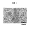
Fig. 3] Fig. 3 is a view illustrating a result of image observation with alternate current heating. - As mentioned above, heating of a sample is effective for preventing the occurrence of contaminants on the sample surface in a high vacuum environment. This anti-contaminant effect is obtained at a heating temperature of about 50°C and becomes marked as the temperature is increased. However, an excessively high temperature causes changes in the microstructure or the quality of the sample. Thus, it is necessary that the heating temperature be set in accordance with the types of samples. For example, the heating temperature is preferably about 100°C when inorganic materials or metallic materials are the subjects. This is because changes or deteriorations of the samples are negligible as long as the heating temperature is about 100°C because the element will be diffused to a distance of only 1% or less relative to the crystal grain size during the period of time from several ten seconds to several minutes which is necessary for image observation or elementary analysis. For example, carbon analysis with respect to a steel material including ferrite grains with an average particle diameter of 10 µm will be discussed. Since the diffusion coefficient of carbon at 100°C is about 2 x 10-14 cm2/s, the diffusion distance will be about 85 nm even after heating for as long as 1 hour. Thus, such heating does not cause a problematic reduction of the accuracy in image observation or elementary analysis in a usual analysis time.
- When a sample is heated with a usual metallic wire heater such as nichrome wire or tungsten wire in a high vacuum environment, the heat that flows from the heater into the sample and the sample holder does not balance with the heat that flows out to surrounding structures via thermal conduction even with feedback/feed forward control based on temperature measurement. As a result, the temperature of the sample or the sample holder hunts up and down, and this phenomenon results in a thermal drift due to thermal expansion. The occurrence of a thermal drift is problematic in that the field of view is moved during observation to make it difficult to ensure the positional accuracy in image observation or elementary analysis. Thus, the present invention uses a PTC thermistor capable of suppressing temperature changes of itself by itself as the heating element, and thereby suppresses the occurrence of a thermal drift in the sample or the sample holder.
- Thermistors are resistors whose electrical resistance varies significantly with temperature, and PTC thermistors are a type of thermistors which increases the electrical resistance with temperature increase. This type of thermistors operates nonlinearly such that the resistance is increased sharply above the Curie temperature. When an electric current is passed therethrough continuously, the thermistors are self-heated and come to allow less current to flow, thereby maintaining a constant temperature. This is how the thermistors function as constant temperature heating elements. In this manner, the PTC thermistors have a self-temperature-regulating function and allow the temperature to be raised rapidly without the occurrence of hunting at the set temperature. Thus, the PTC thermistors serve as highly effective heating elements for the suppression of the occurrence of a thermal drift.
- A ceramic PTC thermistor including barium titanate with additives is a suitable PTC thermistor because this thermistor exhibits thermistor characteristics as a result of the phase transition of barium titanate from the stable tetragonal form at room temperature to the stable cubic form at 120°C or above, as well as because the set temperature (the Curie temperature) can be adjusted in the range from less than 100°C to about 300°C by controlling the amounts of the additives.
- In the use of the PTC thermistor, it is preferable that the thermistor be allowed to generate heat by passing a direct current therethrough. If an alternate current is used, an alternate current magnetic field is generated around the current flow channel including the thermistor to cause the applied electron beam to be oscillated, thus resulting in problems such as distorted or blurred electron microscope images and misplaced analysis positions. Consequently, serious problems are encountered in the recording of electron microscope images or the analysis of ultrafine regions particularly at a high magnification where the accurate application of the electron beam is important. On the other hand, the use of a direct current is free from such problems because only a static magnetic field is produced.
- Further, contaminants can be reduced more stably by using a direct current in combination with the application of plasma or oxygen radicals.
- Even if the temperature of the heating element is constant, disadvantages are caused by heat transfer members such as a sample holder holding the heating element which have a large thermal expansion coefficient because their thermal drift is likely to affect the sample immobilized on such members. Thus, it is desirable that low thermal expansion coefficient alloys such as FeNi36 alloy be used for members which are placed in close contact with the sample directly or indirectly and are thus likely to be brought to an elevated temperature by conductive heating.
- The use of the PTC thermistor eliminates the need for evacuating the device to an ultrahigh vacuum or performing Ar sputtering, and the sample surface is allowed to remain intact.
- An inventive sample heating holder was provided in which a ceramic PTC thermistor having a Curie temperature of 92°C, a service voltage of 100 V and a stable current of 32 mA was immobilized on an existing aluminum sample holder for a scanning electron microscope through a double-sided copper tape (a copper-containing double-sided tape). A comparative PID-controllable sample heating holder was provided in which an insulating-coated nichrome wire heater and a thermocouple were immobilized on the similar aluminum sample holder through the copper tape. The following test was performed using these sample heating holders.
- A commercially available specular polished silicon wafer was cleaned with isopropyl alcohol for 10 minutes and was dried in air. This wafer as a sample was immobilized to the heating section of the sample heating holder through the double-sided copper tape, and the holder was set onto the sample stage of scanning electron microscope SUPRA 55VP manufactured by Carl Zeiss. The amounts of contaminants and the amounts of thermal drift at the set temperatures of room temperature (28°C) and 92°C were measured by the methods described below. To each of the sample heating holders, a direct current voltage was applied via a current inlet terminal mounted on the front side of the SUPRA 55VP sample stage. Here, a temperature-controlling microprocessor was connected to the comparative sample heating holder so that the temperature could be PID-controlled at 92°C. The scanning electron microscope was operated under the conditions in which accelerating voltage: 5 kV, probe current: 0.1 nA, electron beam illumination time: 500 sec, and observation magnification: x100000. To avoid any influence of charge up, the sample in each sample heating holder was grounded to the aluminum holder through a commercially available conductive Cu tape.
- Amounts of contaminants: With use of an energy dispersive X-ray spectrometer mounted on the scanning electron microscope, the amount of contaminants was evaluated based on the integral intensity of the Kα line of carbon (C) on the sample surface (the peak intensity including the background, referred to simply as "integral C intensity) that was integrated during the electron beam illumination time.
- Amounts of thermal drift: The amount of thermal drift was evaluated based on the distance of movement of the observation field of view during the electron beam illumination time.
- The results are described in Table 1.
- In both cases of the inventive sample heating holder and the comparative sample heating holder, the amounts of contaminants (the integral C intensities) were large at room temperature but were decreased to the background level when the temperature was raised to 92°C.
- On the other hand, the amounts of thermal drift (the distances of movement of the field of view) in both cases were as small as 10 nm at room temperature. However, a marked difference was observed between the holders when the temperature was raised to 92°C. The inventive sample heating holder had as small a drift as 90 nm, the level permitting tracking of the position of image observation or elementary analysis. The drift in the comparative sample heating holder was more than 1000 nm which would make tracking of the position of image observation or elementary analysis infeasible.
- From the above, the use of the inventive sample heating holder allows the temperature to be automatically controlled to the target temperature only with the need for a connection to a power source (without a specific temperature-controlling circuit). Accordingly, the sample can be heated in such a manner that the occurrence of contaminants on the sample surface can be prevented and the occurrence of a thermal drift can be suppressed. Thus, image observation and elementary analysis can be performed with high accuracy.
[Table 1] Sample heating holders Integral C intensities (cps) View field movement distance (nm) 28°C 92°C 28°C 92°C Inventive Example 520 9 10 90 Comparative Example 511 12 10 1350 - Instead of the silicon wafer used in EXAMPLE 1, pure iron (a commercially available plate-shaped standard sample: 99.9% purity) as a sample was immobilized to the inventive sample heating holder. The amount of contaminants (the integral C intensity) on the sample surface was measured for various durations of electron beam illumination time while performing heating, while performing heating plus the application of oxygen radicals, or while the sample remained untreated without heating. Here, the heating was carried out under the similar conditions as in EXAMPLE 1, and the oxygen radicals were applied with a commercial high-frequency plasma generator. Changes with time of the amount of contaminants were measured for up to an illumination time of 60 minutes in view of the facts that the surface of pure iron was active and more susceptible to the attachment of contaminants than silicon wafers, and the analysis would be inhibited by contaminants if the electron beam had been applied for a prolonged time. The measurement was performed under the similar conditions as in EXAMPLE 1. A plurality of pure iron samples that had been ultrasonically cleaned with acetone were provided, and each sample was analyzed five times for each duration of time, the obtained amounts of contaminants being averaged.
- The results are described in
Fig. 1 . - It has been shown that when the sample is heated with use of the inventive sample heating holder, the increase in the amount of contaminants is significantly suppressed even after 60 minutes of the application of electron beam as compared to when the sample is untreated without heating. Further, it has been illustrated that the amount of contaminants can be reduced more stably by performing heating in combination with the application of oxygen radicals.
- The following test was performed using an inventive sample heating holder similar to that used in EXAMPLE 1 in which a ceramic PTC thermistor having a Curie temperature of 92°C, a service voltage of 100 V and a stable current of 32 mA was immobilized on an existing aluminum sample holder for a scanning electron microscope through a double-sided copper tape (a copper-containing double-sided tape).
- A commercially available ultralow carbon steel sheet was etched with Nital, then cleaned with alcohol and dried in air. This steel sheet as a sample was immobilized to the heating section of the sample heating holder through the double-sided copper tape, and the holder was set onto the sample stage of scanning electron microscope SUPRA 55VP manufactured by Carl Zeiss. Image observation was performed with the temperature set at 92°C. Here, the image observation was made while applying a direct current voltage or an alternate current voltage to the sample heating holder via a current inlet terminal mounted on the front side of the SUPRA 55VP sample stage. The scanning electron microscope was operated under the conditions in which accelerating voltage: 5 kV, probe current: 0.1 nA, electron beam illumination time: 500 sec, and observation magnification: x10000. To avoid any influence of charge up, the sample in the sample heating holder was grounded to the aluminum holder through a commercially available conductive Cu tape.
- The result of image observation with direct current heating is shown in
Fig. 2 , and the result of image observation with alternate current heating is given inFig. 3 . It has been illustrated that alternate current heating produces a magnetic field which makes the image very unclear due to the appearance of electric noise in the observed image, whilst direct current heating allows for clear image observation without the appearance of electric noise in the observed image and while preventing the increase of contaminants.
Claims (3)
- A sample heating holder for an electron beam microscope or analyzer with excellent performance in the suppression of the growth of carbon contaminations and the occurrence of a thermal drift during observation and analysis, the sample heating holder comprising a positive temperature coefficient (PTC) thermistor as a heating element.
- A method for heating a sample in an electron beam microscope or analyzer while excellently suppressing the growth of carbon contaminations and the occurrence of a thermal drift during observation and analysis, the method being characterized in that the sample heating holder described in claim 1 is used and heat is generated by passing a direct current through the PTC thermistor.
- The method for heating a sample in an electron beam microscope or analyzer while excellently suppressing the growth of carbon contaminations and the occurrence of a thermal drift during observation and analysis according to claim 2, wherein a plasma or oxygen radicals are applied.
Applications Claiming Priority (2)
| Application Number | Priority Date | Filing Date | Title |
|---|---|---|---|
| JP2011200053A JP5935270B2 (en) | 2010-09-16 | 2011-09-14 | Sample heating holder for microscope or analyzer using electron beam, and sample heating method using the same |
| PCT/JP2012/071924 WO2013038910A1 (en) | 2011-09-14 | 2012-08-23 | Sample heating holder for microscope or analysis equipment that uses electron beam, and sample heating method that uses sample heating holder |
Publications (3)
| Publication Number | Publication Date |
|---|---|
| EP2757572A1 true EP2757572A1 (en) | 2014-07-23 |
| EP2757572A4 EP2757572A4 (en) | 2015-05-06 |
| EP2757572B1 EP2757572B1 (en) | 2020-06-03 |
Family
ID=47884032
Family Applications (1)
| Application Number | Title | Priority Date | Filing Date |
|---|---|---|---|
| EP12831362.4A Active EP2757572B1 (en) | 2011-09-14 | 2012-08-23 | Sample heating method using sample heating holder for electron beam microscopes or analyzers |
Country Status (4)
| Country | Link |
|---|---|
| EP (1) | EP2757572B1 (en) |
| KR (1) | KR101647901B1 (en) |
| CN (1) | CN103782363B (en) |
| WO (1) | WO2013038910A1 (en) |
Cited By (1)
| Publication number | Priority date | Publication date | Assignee | Title |
|---|---|---|---|---|
| EP3226278A4 (en) * | 2014-11-28 | 2017-12-27 | JFE Steel Corporation | Quantitative analysis device for trace carbon and quantitative analysis method for trace carbon |
Family Cites Families (20)
| Publication number | Priority date | Publication date | Assignee | Title |
|---|---|---|---|---|
| US3418465A (en) * | 1965-08-17 | 1968-12-24 | Zeiss Jena Veb Carl | Radiation source for reducing specimen contamination in electron microscopes |
| US3996447A (en) * | 1974-11-29 | 1976-12-07 | Texas Instruments Incorporated | PTC resistance heater |
| JPH0274026A (en) * | 1988-09-09 | 1990-03-14 | Jeol Ltd | Electron beam device |
| JPH05128988A (en) * | 1991-10-31 | 1993-05-25 | Hitachi Ltd | Electron beam equipment |
| JPH05215702A (en) * | 1992-02-01 | 1993-08-24 | Nippon Oil & Fats Co Ltd | Water content detector |
| US5296669A (en) * | 1992-05-29 | 1994-03-22 | Hitachi, Ltd. | Specimen heating device for use with an electron microscope |
| JPH0963527A (en) * | 1995-08-18 | 1997-03-07 | Mitsubishi Electric Corp | Contamination reduction device |
| JP2004063463A (en) * | 1996-08-08 | 2004-02-26 | Hitachi Ltd | Operating method of electron microscope and electron microscope |
| JPH11116209A (en) * | 1997-10-21 | 1999-04-27 | Toto Ltd | Corona discharge element |
| US6610257B2 (en) | 1999-01-11 | 2003-08-26 | Ronald A. Vane | Low RF power electrode for plasma generation of oxygen radicals from air |
| US6105589A (en) | 1999-01-11 | 2000-08-22 | Vane; Ronald A. | Oxidative cleaning method and apparatus for electron microscopes using an air plasma as an oxygen radical source |
| JP2000133189A (en) * | 1999-10-25 | 2000-05-12 | Natl Res Inst For Metals | Electron microscope equipment |
| US6452315B1 (en) | 2000-02-08 | 2002-09-17 | Ronald A. Vane | Compact RF plasma device for cleaning electron microscopes and vacuum chambers |
| NL1027025C2 (en) * | 2004-09-13 | 2006-03-14 | Univ Delft Tech | Microreactor for a transmission electron microscope and heating element and method for manufacturing thereof. |
| JP2007149449A (en) * | 2005-11-25 | 2007-06-14 | Horon:Kk | Device and method for preventing charged contamination |
| JP4991144B2 (en) * | 2005-11-30 | 2012-08-01 | 株式会社日立ハイテクノロジーズ | Sample measuring method and charged particle beam apparatus |
| EP2278306A1 (en) * | 2009-07-13 | 2011-01-26 | Fei Company | Method for inspecting a sample |
| JP2011034895A (en) * | 2009-08-05 | 2011-02-17 | Hitachi High-Technologies Corp | Charged particle beam device and sample decontamination mechanism |
| KR20120093834A (en) * | 2009-10-06 | 2012-08-23 | 히다찌긴조꾸가부시끼가이사 | Semiconductor ceramic composition, method for producing same, ptc element and heat generating module |
| CN201829449U (en) * | 2010-09-26 | 2011-05-11 | 攀钢集团钢铁钒钛股份有限公司 | Special scanning electron microscope clamp for inlaying samples |
-
2012
- 2012-08-23 KR KR1020147006903A patent/KR101647901B1/en active Active
- 2012-08-23 WO PCT/JP2012/071924 patent/WO2013038910A1/en not_active Ceased
- 2012-08-23 EP EP12831362.4A patent/EP2757572B1/en active Active
- 2012-08-23 CN CN201280043932.3A patent/CN103782363B/en active Active
Cited By (2)
| Publication number | Priority date | Publication date | Assignee | Title |
|---|---|---|---|---|
| EP3226278A4 (en) * | 2014-11-28 | 2017-12-27 | JFE Steel Corporation | Quantitative analysis device for trace carbon and quantitative analysis method for trace carbon |
| US10151718B2 (en) | 2014-11-28 | 2018-12-11 | Jfe Steel Corporation | Quantitative analysis device for trace carbon and quantitative analysis method for trace carbon |
Also Published As
| Publication number | Publication date |
|---|---|
| KR20140061451A (en) | 2014-05-21 |
| EP2757572B1 (en) | 2020-06-03 |
| KR101647901B1 (en) | 2016-08-11 |
| CN103782363A (en) | 2014-05-07 |
| CN103782363B (en) | 2017-04-05 |
| WO2013038910A1 (en) | 2013-03-21 |
| EP2757572A4 (en) | 2015-05-06 |
Similar Documents
| Publication | Publication Date | Title |
|---|---|---|
| Boxman et al. | Vacuum arc deposition devices | |
| US5895586A (en) | Plasma processing apparatus and plasma processing method in which a part of the processing chamber is formed using a pre-fluorinated material of aluminum | |
| JPH0456420B2 (en) | ||
| US3305473A (en) | Triode sputtering apparatus for depositing uniform coatings | |
| US8742346B1 (en) | Sputter removal of material from microscopy samples with RF generated plasma | |
| US20130269607A1 (en) | Plasma cvd apparatus | |
| DE112014002868B4 (en) | ion etching apparatus and processing method using the ion etching apparatus | |
| KR101438129B1 (en) | Sputtering apparatus | |
| WO2014208307A1 (en) | Ion milling device | |
| KR20210002112A (en) | Metal protective layer with diffusion barrier for electron emitters | |
| EP2757572B1 (en) | Sample heating method using sample heating holder for electron beam microscopes or analyzers | |
| JP5935270B2 (en) | Sample heating holder for microscope or analyzer using electron beam, and sample heating method using the same | |
| Métois et al. | An ultra-high-vacuum transmission and scanning electron microscope for crystal growth experiments | |
| Russo et al. | UHV arc for high quality film deposition | |
| US6967334B2 (en) | Ion source and ion beam device | |
| US20090138995A1 (en) | Atom probe component treatments | |
| Hofmann | Practice of Surface and Interface Analysis with AES and XPS | |
| Grant et al. | Surface science aspects of contamination in TEM sample preparation | |
| Shaik et al. | On the quality of hydrogenated amorphous silicon deposited by sputtering | |
| US20090321248A1 (en) | Low damage sputtering system and method | |
| Paik et al. | The characterization of a magnetron-sputter-type negative-ion source | |
| JP2002359233A (en) | Plasma processing equipment | |
| Golan et al. | Investigation of low-pressure plane plasma discharge | |
| Russo et al. | Arco project status report | |
| Grant et al. | results from these experiments will be discussed. |
Legal Events
| Date | Code | Title | Description |
|---|---|---|---|
| PUAI | Public reference made under article 153(3) epc to a published international application that has entered the european phase |
Free format text: ORIGINAL CODE: 0009012 |
|
| 17P | Request for examination filed |
Effective date: 20140326 |
|
| AK | Designated contracting states |
Kind code of ref document: A1 Designated state(s): AL AT BE BG CH CY CZ DE DK EE ES FI FR GB GR HR HU IE IS IT LI LT LU LV MC MK MT NL NO PL PT RO RS SE SI SK SM TR |
|
| DAX | Request for extension of the european patent (deleted) | ||
| RA4 | Supplementary search report drawn up and despatched (corrected) |
Effective date: 20150409 |
|
| RIC1 | Information provided on ipc code assigned before grant |
Ipc: H01J 37/20 20060101AFI20150401BHEP |
|
| STAA | Information on the status of an ep patent application or granted ep patent |
Free format text: STATUS: EXAMINATION IS IN PROGRESS |
|
| 17Q | First examination report despatched |
Effective date: 20161108 |
|
| GRAP | Despatch of communication of intention to grant a patent |
Free format text: ORIGINAL CODE: EPIDOSNIGR1 |
|
| STAA | Information on the status of an ep patent application or granted ep patent |
Free format text: STATUS: GRANT OF PATENT IS INTENDED |
|
| INTG | Intention to grant announced |
Effective date: 20200220 |
|
| GRAS | Grant fee paid |
Free format text: ORIGINAL CODE: EPIDOSNIGR3 |
|
| GRAA | (expected) grant |
Free format text: ORIGINAL CODE: 0009210 |
|
| STAA | Information on the status of an ep patent application or granted ep patent |
Free format text: STATUS: THE PATENT HAS BEEN GRANTED |
|
| AK | Designated contracting states |
Kind code of ref document: B1 Designated state(s): AL AT BE BG CH CY CZ DE DK EE ES FI FR GB GR HR HU IE IS IT LI LT LU LV MC MK MT NL NO PL PT RO RS SE SI SK SM TR |
|
| REG | Reference to a national code |
Ref country code: GB Ref legal event code: FG4D |
|
| REG | Reference to a national code |
Ref country code: CH Ref legal event code: EP Ref country code: AT Ref legal event code: REF Ref document number: 1277894 Country of ref document: AT Kind code of ref document: T Effective date: 20200615 |
|
| REG | Reference to a national code |
Ref country code: DE Ref legal event code: R096 Ref document number: 602012070527 Country of ref document: DE |
|
| REG | Reference to a national code |
Ref country code: LT Ref legal event code: MG4D |
|
| PG25 | Lapsed in a contracting state [announced via postgrant information from national office to epo] |
Ref country code: SE Free format text: LAPSE BECAUSE OF FAILURE TO SUBMIT A TRANSLATION OF THE DESCRIPTION OR TO PAY THE FEE WITHIN THE PRESCRIBED TIME-LIMIT Effective date: 20200603 Ref country code: NO Free format text: LAPSE BECAUSE OF FAILURE TO SUBMIT A TRANSLATION OF THE DESCRIPTION OR TO PAY THE FEE WITHIN THE PRESCRIBED TIME-LIMIT Effective date: 20200903 Ref country code: FI Free format text: LAPSE BECAUSE OF FAILURE TO SUBMIT A TRANSLATION OF THE DESCRIPTION OR TO PAY THE FEE WITHIN THE PRESCRIBED TIME-LIMIT Effective date: 20200603 Ref country code: GR Free format text: LAPSE BECAUSE OF FAILURE TO SUBMIT A TRANSLATION OF THE DESCRIPTION OR TO PAY THE FEE WITHIN THE PRESCRIBED TIME-LIMIT Effective date: 20200904 Ref country code: LT Free format text: LAPSE BECAUSE OF FAILURE TO SUBMIT A TRANSLATION OF THE DESCRIPTION OR TO PAY THE FEE WITHIN THE PRESCRIBED TIME-LIMIT Effective date: 20200603 |
|
| REG | Reference to a national code |
Ref country code: NL Ref legal event code: MP Effective date: 20200603 |
|
| PG25 | Lapsed in a contracting state [announced via postgrant information from national office to epo] |
Ref country code: LV Free format text: LAPSE BECAUSE OF FAILURE TO SUBMIT A TRANSLATION OF THE DESCRIPTION OR TO PAY THE FEE WITHIN THE PRESCRIBED TIME-LIMIT Effective date: 20200603 Ref country code: HR Free format text: LAPSE BECAUSE OF FAILURE TO SUBMIT A TRANSLATION OF THE DESCRIPTION OR TO PAY THE FEE WITHIN THE PRESCRIBED TIME-LIMIT Effective date: 20200603 Ref country code: RS Free format text: LAPSE BECAUSE OF FAILURE TO SUBMIT A TRANSLATION OF THE DESCRIPTION OR TO PAY THE FEE WITHIN THE PRESCRIBED TIME-LIMIT Effective date: 20200603 Ref country code: BG Free format text: LAPSE BECAUSE OF FAILURE TO SUBMIT A TRANSLATION OF THE DESCRIPTION OR TO PAY THE FEE WITHIN THE PRESCRIBED TIME-LIMIT Effective date: 20200903 |
|
| REG | Reference to a national code |
Ref country code: AT Ref legal event code: MK05 Ref document number: 1277894 Country of ref document: AT Kind code of ref document: T Effective date: 20200603 |
|
| PG25 | Lapsed in a contracting state [announced via postgrant information from national office to epo] |
Ref country code: NL Free format text: LAPSE BECAUSE OF FAILURE TO SUBMIT A TRANSLATION OF THE DESCRIPTION OR TO PAY THE FEE WITHIN THE PRESCRIBED TIME-LIMIT Effective date: 20200603 Ref country code: AL Free format text: LAPSE BECAUSE OF FAILURE TO SUBMIT A TRANSLATION OF THE DESCRIPTION OR TO PAY THE FEE WITHIN THE PRESCRIBED TIME-LIMIT Effective date: 20200603 |
|
| REG | Reference to a national code |
Ref country code: DE Ref legal event code: R082 Ref document number: 602012070527 Country of ref document: DE Representative=s name: HL KEMPNER PATENTANWAELTE, SOLICITORS (ENGLAND, DE Ref country code: DE Ref legal event code: R082 Ref document number: 602012070527 Country of ref document: DE Representative=s name: HL KEMPNER PATENTANWALT, RECHTSANWALT, SOLICIT, DE Ref country code: DE Ref legal event code: R082 Ref document number: 602012070527 Country of ref document: DE Representative=s name: HL KEMPNER PARTG MBB, DE |
|
| PG25 | Lapsed in a contracting state [announced via postgrant information from national office to epo] |
Ref country code: CZ Free format text: LAPSE BECAUSE OF FAILURE TO SUBMIT A TRANSLATION OF THE DESCRIPTION OR TO PAY THE FEE WITHIN THE PRESCRIBED TIME-LIMIT Effective date: 20200603 Ref country code: PT Free format text: LAPSE BECAUSE OF FAILURE TO SUBMIT A TRANSLATION OF THE DESCRIPTION OR TO PAY THE FEE WITHIN THE PRESCRIBED TIME-LIMIT Effective date: 20201006 Ref country code: RO Free format text: LAPSE BECAUSE OF FAILURE TO SUBMIT A TRANSLATION OF THE DESCRIPTION OR TO PAY THE FEE WITHIN THE PRESCRIBED TIME-LIMIT Effective date: 20200603 Ref country code: SM Free format text: LAPSE BECAUSE OF FAILURE TO SUBMIT A TRANSLATION OF THE DESCRIPTION OR TO PAY THE FEE WITHIN THE PRESCRIBED TIME-LIMIT Effective date: 20200603 Ref country code: IT Free format text: LAPSE BECAUSE OF FAILURE TO SUBMIT A TRANSLATION OF THE DESCRIPTION OR TO PAY THE FEE WITHIN THE PRESCRIBED TIME-LIMIT Effective date: 20200603 Ref country code: AT Free format text: LAPSE BECAUSE OF FAILURE TO SUBMIT A TRANSLATION OF THE DESCRIPTION OR TO PAY THE FEE WITHIN THE PRESCRIBED TIME-LIMIT Effective date: 20200603 Ref country code: EE Free format text: LAPSE BECAUSE OF FAILURE TO SUBMIT A TRANSLATION OF THE DESCRIPTION OR TO PAY THE FEE WITHIN THE PRESCRIBED TIME-LIMIT Effective date: 20200603 Ref country code: ES Free format text: LAPSE BECAUSE OF FAILURE TO SUBMIT A TRANSLATION OF THE DESCRIPTION OR TO PAY THE FEE WITHIN THE PRESCRIBED TIME-LIMIT Effective date: 20200603 |
|
| PG25 | Lapsed in a contracting state [announced via postgrant information from national office to epo] |
Ref country code: SK Free format text: LAPSE BECAUSE OF FAILURE TO SUBMIT A TRANSLATION OF THE DESCRIPTION OR TO PAY THE FEE WITHIN THE PRESCRIBED TIME-LIMIT Effective date: 20200603 Ref country code: PL Free format text: LAPSE BECAUSE OF FAILURE TO SUBMIT A TRANSLATION OF THE DESCRIPTION OR TO PAY THE FEE WITHIN THE PRESCRIBED TIME-LIMIT Effective date: 20200603 Ref country code: IS Free format text: LAPSE BECAUSE OF FAILURE TO SUBMIT A TRANSLATION OF THE DESCRIPTION OR TO PAY THE FEE WITHIN THE PRESCRIBED TIME-LIMIT Effective date: 20201003 |
|
| REG | Reference to a national code |
Ref country code: DE Ref legal event code: R097 Ref document number: 602012070527 Country of ref document: DE |
|
| PG25 | Lapsed in a contracting state [announced via postgrant information from national office to epo] |
Ref country code: MC Free format text: LAPSE BECAUSE OF FAILURE TO SUBMIT A TRANSLATION OF THE DESCRIPTION OR TO PAY THE FEE WITHIN THE PRESCRIBED TIME-LIMIT Effective date: 20200603 |
|
| REG | Reference to a national code |
Ref country code: CH Ref legal event code: PL |
|
| PLBE | No opposition filed within time limit |
Free format text: ORIGINAL CODE: 0009261 |
|
| STAA | Information on the status of an ep patent application or granted ep patent |
Free format text: STATUS: NO OPPOSITION FILED WITHIN TIME LIMIT |
|
| PG25 | Lapsed in a contracting state [announced via postgrant information from national office to epo] |
Ref country code: LU Free format text: LAPSE BECAUSE OF NON-PAYMENT OF DUE FEES Effective date: 20200823 Ref country code: DK Free format text: LAPSE BECAUSE OF FAILURE TO SUBMIT A TRANSLATION OF THE DESCRIPTION OR TO PAY THE FEE WITHIN THE PRESCRIBED TIME-LIMIT Effective date: 20200603 Ref country code: CH Free format text: LAPSE BECAUSE OF NON-PAYMENT OF DUE FEES Effective date: 20200831 Ref country code: LI Free format text: LAPSE BECAUSE OF NON-PAYMENT OF DUE FEES Effective date: 20200831 |
|
| 26N | No opposition filed |
Effective date: 20210304 |
|
| GBPC | Gb: european patent ceased through non-payment of renewal fee |
Effective date: 20200903 |
|
| REG | Reference to a national code |
Ref country code: BE Ref legal event code: MM Effective date: 20200831 |
|
| PG25 | Lapsed in a contracting state [announced via postgrant information from national office to epo] |
Ref country code: SI Free format text: LAPSE BECAUSE OF FAILURE TO SUBMIT A TRANSLATION OF THE DESCRIPTION OR TO PAY THE FEE WITHIN THE PRESCRIBED TIME-LIMIT Effective date: 20200603 |
|
| PG25 | Lapsed in a contracting state [announced via postgrant information from national office to epo] |
Ref country code: FR Free format text: LAPSE BECAUSE OF NON-PAYMENT OF DUE FEES Effective date: 20200831 |
|
| PG25 | Lapsed in a contracting state [announced via postgrant information from national office to epo] |
Ref country code: GB Free format text: LAPSE BECAUSE OF NON-PAYMENT OF DUE FEES Effective date: 20200903 Ref country code: IE Free format text: LAPSE BECAUSE OF NON-PAYMENT OF DUE FEES Effective date: 20200823 Ref country code: BE Free format text: LAPSE BECAUSE OF NON-PAYMENT OF DUE FEES Effective date: 20200831 |
|
| PG25 | Lapsed in a contracting state [announced via postgrant information from national office to epo] |
Ref country code: TR Free format text: LAPSE BECAUSE OF FAILURE TO SUBMIT A TRANSLATION OF THE DESCRIPTION OR TO PAY THE FEE WITHIN THE PRESCRIBED TIME-LIMIT Effective date: 20200603 Ref country code: MT Free format text: LAPSE BECAUSE OF FAILURE TO SUBMIT A TRANSLATION OF THE DESCRIPTION OR TO PAY THE FEE WITHIN THE PRESCRIBED TIME-LIMIT Effective date: 20200603 Ref country code: CY Free format text: LAPSE BECAUSE OF FAILURE TO SUBMIT A TRANSLATION OF THE DESCRIPTION OR TO PAY THE FEE WITHIN THE PRESCRIBED TIME-LIMIT Effective date: 20200603 |
|
| PG25 | Lapsed in a contracting state [announced via postgrant information from national office to epo] |
Ref country code: MK Free format text: LAPSE BECAUSE OF FAILURE TO SUBMIT A TRANSLATION OF THE DESCRIPTION OR TO PAY THE FEE WITHIN THE PRESCRIBED TIME-LIMIT Effective date: 20200603 |
|
| PGFP | Annual fee paid to national office [announced via postgrant information from national office to epo] |
Ref country code: DE Payment date: 20250702 Year of fee payment: 14 |