EP2757324A2 - Verfahren zum Messen von Volumenströmen - Google Patents
Verfahren zum Messen von Volumenströmen Download PDFInfo
- Publication number
- EP2757324A2 EP2757324A2 EP14150302.9A EP14150302A EP2757324A2 EP 2757324 A2 EP2757324 A2 EP 2757324A2 EP 14150302 A EP14150302 A EP 14150302A EP 2757324 A2 EP2757324 A2 EP 2757324A2
- Authority
- EP
- European Patent Office
- Prior art keywords
- measuring
- volume flow
- heat sink
- flow
- heating circuit
- Prior art date
- Legal status (The legal status is an assumption and is not a legal conclusion. Google has not performed a legal analysis and makes no representation as to the accuracy of the status listed.)
- Granted
Links
Images
Classifications
-
- F—MECHANICAL ENGINEERING; LIGHTING; HEATING; WEAPONS; BLASTING
- F24—HEATING; RANGES; VENTILATING
- F24D—DOMESTIC- OR SPACE-HEATING SYSTEMS, e.g. CENTRAL HEATING SYSTEMS; DOMESTIC HOT-WATER SUPPLY SYSTEMS; ELEMENTS OR COMPONENTS THEREFOR
- F24D19/00—Details
- F24D19/10—Arrangement or mounting of control or safety devices
- F24D19/1006—Arrangement or mounting of control or safety devices for water heating systems
- F24D19/1009—Arrangement or mounting of control or safety devices for water heating systems for central heating
- F24D19/1015—Arrangement or mounting of control or safety devices for water heating systems for central heating using a valve or valves
- F24D19/1024—Arrangement or mounting of control or safety devices for water heating systems for central heating using a valve or valves a multiple way valve
-
- F—MECHANICAL ENGINEERING; LIGHTING; HEATING; WEAPONS; BLASTING
- F24—HEATING; RANGES; VENTILATING
- F24D—DOMESTIC- OR SPACE-HEATING SYSTEMS, e.g. CENTRAL HEATING SYSTEMS; DOMESTIC HOT-WATER SUPPLY SYSTEMS; ELEMENTS OR COMPONENTS THEREFOR
- F24D19/00—Details
- F24D19/10—Arrangement or mounting of control or safety devices
- F24D19/1006—Arrangement or mounting of control or safety devices for water heating systems
- F24D19/1009—Arrangement or mounting of control or safety devices for water heating systems for central heating
-
- G—PHYSICS
- G01—MEASURING; TESTING
- G01F—MEASURING VOLUME, VOLUME FLOW, MASS FLOW OR LIQUID LEVEL; METERING BY VOLUME
- G01F1/00—Measuring the volume flow or mass flow of fluid or fluent solid material wherein the fluid passes through a meter in a continuous flow
- G01F1/05—Measuring the volume flow or mass flow of fluid or fluent solid material wherein the fluid passes through a meter in a continuous flow by using mechanical effects
- G01F1/20—Measuring the volume flow or mass flow of fluid or fluent solid material wherein the fluid passes through a meter in a continuous flow by using mechanical effects by detection of dynamic effects of the flow
- G01F1/32—Measuring the volume flow or mass flow of fluid or fluent solid material wherein the fluid passes through a meter in a continuous flow by using mechanical effects by detection of dynamic effects of the flow using swirl flowmeters
-
- G—PHYSICS
- G01—MEASURING; TESTING
- G01F—MEASURING VOLUME, VOLUME FLOW, MASS FLOW OR LIQUID LEVEL; METERING BY VOLUME
- G01F5/00—Measuring a proportion of the volume flow
-
- F—MECHANICAL ENGINEERING; LIGHTING; HEATING; WEAPONS; BLASTING
- F24—HEATING; RANGES; VENTILATING
- F24D—DOMESTIC- OR SPACE-HEATING SYSTEMS, e.g. CENTRAL HEATING SYSTEMS; DOMESTIC HOT-WATER SUPPLY SYSTEMS; ELEMENTS OR COMPONENTS THEREFOR
- F24D2220/00—Components of central heating installations excluding heat sources
- F24D2220/04—Sensors
- F24D2220/044—Flow sensors
-
- F—MECHANICAL ENGINEERING; LIGHTING; HEATING; WEAPONS; BLASTING
- F24—HEATING; RANGES; VENTILATING
- F24D—DOMESTIC- OR SPACE-HEATING SYSTEMS, e.g. CENTRAL HEATING SYSTEMS; DOMESTIC HOT-WATER SUPPLY SYSTEMS; ELEMENTS OR COMPONENTS THEREFOR
- F24D2220/00—Components of central heating installations excluding heat sources
- F24D2220/20—Heat consumers
- F24D2220/2081—Floor or wall heating panels
-
- F—MECHANICAL ENGINEERING; LIGHTING; HEATING; WEAPONS; BLASTING
- F24—HEATING; RANGES; VENTILATING
- F24D—DOMESTIC- OR SPACE-HEATING SYSTEMS, e.g. CENTRAL HEATING SYSTEMS; DOMESTIC HOT-WATER SUPPLY SYSTEMS; ELEMENTS OR COMPONENTS THEREFOR
- F24D3/00—Hot-water central heating systems
- F24D3/12—Tube and panel arrangements for ceiling, wall, or underfloor heating
-
- Y—GENERAL TAGGING OF NEW TECHNOLOGICAL DEVELOPMENTS; GENERAL TAGGING OF CROSS-SECTIONAL TECHNOLOGIES SPANNING OVER SEVERAL SECTIONS OF THE IPC; TECHNICAL SUBJECTS COVERED BY FORMER USPC CROSS-REFERENCE ART COLLECTIONS [XRACs] AND DIGESTS
- Y02—TECHNOLOGIES OR APPLICATIONS FOR MITIGATION OR ADAPTATION AGAINST CLIMATE CHANGE
- Y02B—CLIMATE CHANGE MITIGATION TECHNOLOGIES RELATED TO BUILDINGS, e.g. HOUSING, HOUSE APPLIANCES OR RELATED END-USER APPLICATIONS
- Y02B30/00—Energy efficient heating, ventilation or air conditioning [HVAC]
Definitions
- the invention relates to a method for measuring volume flows in heating circuits.
- the generated heat is distributed by means of circulating heating water from the heat source or the heat sources to the heat sinks such as radiators, underfloor heating circuits, etc.
- the flow of locally circulating heating water can be adjusted to the current needs.
- This adaptation to the heat requirement results in low volume flows in the heating system in modern installations.
- Favorable volumetric flow sensors are limited by the underlying principle in the measuring range for small volume flows. This applies, for example, to sensors based on the vortex principle. Below a certain limit, the detection of the volumetric flows is not possible today. Alternatively, sensors with a wide measuring range are available, which can also detect low flow rates. However, these sensors are very expensive.
- Object of this invention is to provide a method with which it is possible to detect low flow rates in the heating circuit with inexpensive sensors can.
- part of the volume flow is conducted parallel to the heat sink over a measuring path.
- the pump head can eg with the in the application DE 102012003502.0 be kept constant.
- a priority switching valve (3-way valve) is moved to a defined mixing position in order to achieve a defined volume flow mixing ratio between the measuring section and the heat sink.
- the now higher volume flow is measured with the existing sensor.
- the priority switching valve is switched again so that the volume flow is conducted exclusively through the heat sink.
- the volume flow is passed once only through the measuring section to determine the flow resistance of the measuring section. This can be done either before each measurement or only once for all measurements or occasionally.
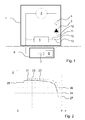
- FIG. 1 shows a heating circuit for carrying out the method according to the invention.
- the primary heat exchanger 2 represents the heat source and is together with a pump 3, the volume flow sensor 4, a measuring section 5 and a priority switching valve 10 are provided in a boiler 1.
- the radiator system is the heat sink 6 and includes a heat exchanger 8 for the discharge of heat and optionally a valve 8, such as a thermostatic valve or a manually operable valve.
- the priority switching valve 10 can be operated so that for measuring the measuring section only the branch 11 is connected to 12, while 13 is shut off, that in normal heating mode only the branch 13 is connected to 12, while 11 is shut off and that for measuring the volume flow the branches 11 and 13 are connected in a defined mixing ratio with 12.
- the measuring section 5 may be a simple connecting pipe, a secondary heat exchanger or a storage.
- FIG. 2 shows the course of the volume flow sensor 4 in FIG. 1 measured volume flow V over the position x of the priority switching valve 10 in FIG. 1 ,
- a value of 1 for x means that the volume flow flows exclusively from branch 13 to branch 12.
- a value of 0 for x means that the volume flow flows exclusively from branch 11 to branch 12. Values between 0 and 1 represent the corresponding mixing ratio.
- the circuit is closed exclusively via the measuring section 5, since the priority switching valve 10 exclusively connects the branches 11 and 12 with each other.
- a volume flow 25 sets through the measuring section.
- the circuit is closed exclusively via the heat sink 6, since the priority switching valve 10 exclusively connects the branches 13 and 12 to each other.
- a first volume flow through the heat sink 26 is established. Since this volume flow is above the threshold value 24, the volume flow through the volume flow sensor 4 can be measured.
- the priority switching valve 10 is operated at a constant pumping head in a position 23 in which a partial flow through the measuring section 5 and the branch 11 and a partial flow through the heat sink 6 and the branch 13 flows. As a result, a higher overall volume flow flows through the branch 12 and the volume flow sensor 4 in total. This is shown in the diagram in FIG. 2 the point of intersection between the vertical line 23 and the second volume flow curve 22.
- the volume flow V ⁇ is measured in position 23. Subsequently, the priority switching valve 10 is operated so that only the branch 13 is connected to the branch 12. The measured volumetric flow is below the threshold value 24 in the lower curve and therefore has to be determined according to the invention in a correction calculation on the basis of the measurement result, while a defined mixing ratio between the branches 13 after 12 and 11 after 12 has been established.
- the method according to the invention is carried out as soon as it is detected that the measured value of the volume flow sensor 4 is below the threshold value 24.
- the method according to the invention is preferably repeated periodically as long as the measured value of the volume flow sensor 4 is below the threshold value 24.
Landscapes
- Engineering & Computer Science (AREA)
- Physics & Mathematics (AREA)
- Thermal Sciences (AREA)
- Chemical & Material Sciences (AREA)
- Combustion & Propulsion (AREA)
- Mechanical Engineering (AREA)
- General Engineering & Computer Science (AREA)
- Fluid Mechanics (AREA)
- General Physics & Mathematics (AREA)
- Steam Or Hot-Water Central Heating Systems (AREA)
- Investigating Or Analyzing Materials Using Thermal Means (AREA)
Abstract
Description
- Die Erfindung betrifft ein Verfahren zum Messen von Volumenströmen in Heizkreisen.
- In zentralheizungsbasierten Wärmeversorgungssystemen wird die erzeugte Wärme mittels zirkulierendem Heizungswasser von der Wärmequelle oder den Wärmequellen zu den Wärmesenken wie Heizkörper, Fußbodenheizkreise etc. verteilt. Durch Stell- und Regeleinrichtungen in den einzelnen Räumen kann dabei der Volumenstrom des lokal zirkulierenden Heizungswassers dem momentanen Bedarf angepasst werden. Diese Anpassung an den Wärmebedarf hat bei modernen Installationen geringe Volumenströme in der Heizungsanlage zur Folge. Günstige Volumenstromsensoren sind durch das zu Grunde liegende Prinzip im Messbereich für kleine Volumenströme eingeschränkt. Dies gilt zum Beispiel für Sensoren, die auf dem Vortex-Prinzip basieren. Unterhalb einer bestimmten Grenze ist die Erfassung der Volumenströme heute nicht möglich. Alternativ stehen Sensoren mit einem breiten Messbereich zur Verfügung, die auch geringe Volumenströme erfassen können. Diese Sensoren sind jedoch sehr teuer.
- Aufgabe dieser Erfindung ist es, ein Verfahren bereitzustellen, mit dem es möglich ist, geringe Volumenströme im Heizkreis auch mit kostengünstigen Sensoren erfassen zu können. Insbesondere ist es Aufgabe der Erfindung, einen Volumenstrom durch den Heizkreis zu messen, der unterhalb des Messbereichs des Sensors liegt.
- Erfindungsgemäß wird, sobald die Unterschreitung des Messbereichs des verwendeten Sensors festgestellt wird, bei konstanter Pumpenförderhöhe ein Teil des Volumenstroms parallel zur Wärmesenke über eine Messstrecke geleitet. Die Pumpenförderhöhe kann z.B. mit dem in der Anmeldung
DE 102012003502.0 beschriebenen Verfahren konstant gehalten werden. Dabei wird ein Vorrangumschaltventil (3-Wege-Ventil) in eine definierte Mischposition verfahren, um ein definiertes Volumenstrom-Mischungsverhältnis zwischen Messstrecke und Wärmesenke zu erreichen. Dabei wird der nun höhere Volumenstrom mit dem vorhandenen Sensor gemessen. Nachdem der Gesamt-Volumenstrom gemessen und der anteilige Volumenstrom durch die Wärmesenke ermittelt wurde, wird das Vorrangumschaltventil wieder so geschaltet, dass der Volumenstrom ausschließlich durch die Wärmesenke geleitet wird. Vor diesem Messvorgang wird der Volumenstrom einmalig ausschließlich durch die Messstrecke geleitet, um den Strömungswiderstand der Messstrecke zu ermitteln. Dies kann entweder vor jedem Messvorgang oder nur einmalig für alle Messvorgänge oder gelegentlich erfolgen. - Die Erfindung wird nun anhand der Figuren detailliert erläutert.
- Es stellen dar:
-
Figur 1 : Einen Heizkreis zum Durchführen des erfindungsgemäßen Verfahrens -
Figur 2 : Darstellung des Verlaufs des gemessenen Volumenstroms über der Stellung des Vorrangumschaltventils -
Figur 1 zeigt einen Heizkreis zur Durchführung des erfindungsgemäßen Verfahrens. Der Primärwärmetauscher 2 stellt die Wärmequelle dar und ist zusammen mit einer Pumpe 3, dem Volumenstromsensor 4, einer Messstrecke 5 und einem Vorrangumschaltventil 10 in einem Heizkessel 1 vorgesehen. Das Radiatorsystem stellt die Wärmesenke 6 dar und umfasst einen Wärmetauscher 8 zur Abgabe der Wärme sowie optional ein Ventil 8, z.B. ein Thermostatventil oder ein manuell betätigbares Ventil. Das Vorrangumschaltventil 10 kann so betrieben werden, dass zum Messen der Messstrecke ausschließlich der Zweig 11 mit 12 verbunden ist, während 13 abgesperrt ist, dass im normalen Heizbetrieb ausschließlich der Zweig 13 mit 12 verbunden ist, während 11 abgesperrt ist und dass zum Messen des Volumenstroms die Zweige 11 und 13 in einem definierten Mischungsverhältnis mit 12 verbunden sind. Die Messstrecke 5 kann ein einfaches Verbindungsrohr, einen sekundären Wärmetauscher oder ein Speicher sein. -
Figur 2 zeigt den Verlauf des vom Volumenstromsensor 4 inFigur 1 gemessenen Volumenstroms V über der Stellung x des Vorrangumschaltventils 10 inFigur 1 . Ein Wert von 1 für x bedeutet, dass der Volumenstrom ausschließlich vom Zweig 13 zum Zweig 12 fließt. Ein Wert von 0 für x bedeutet, dass der Volumenstrom ausschließlich vom Zweig 11 zum Zweig 12 fließt. Werte zwischen 0 und 1 stehen für das entsprechende Mischungsverhältnis. - Dargestellt ist ein erster Volumenstromverlauf 21 und ein zweiter Volumenstromverlauf 22 über dem Wert x. Für den Wert x = 0 ist der Kreislauf ausschließlich über die Messstrecke 5 geschlossen, da das Vorrangumschaltventil 10 ausschließlich die Zweige 11 und 12 miteinander verbindet. Für beide Volumenstromverläufe 21, 22 stellt sich ein Volumenstrom 25 durch die Messstrecke ein. Für den Wert x = 1 ist der Kreislauf ausschließlich über die Wärmesenke 6 geschlossen, da das Vorrangumschaltventil 10 ausschließlich die Zweige 13 und 12 miteinander verbindet. Für den ersten Volumenstromverlauf 21 stellt sich ein erster Volumenstrom durch die Wärmesenke 26 ein. Da dieser Volumenstrom oberhalb des Schwellenwerts 24 liegt, kann der Volumenstrom durch den Volumenstromsensor 4 gemessen werden.
- Für den zweiten Volumenstromverlauf sei angenommen, dass das Ventil 7 in der Wärmesenke 6) stark angedrosselt ist. Dadurch stellt sich ein sehr geringer zweiter Volumenstrom durch die Wärmesenke 27 ein, der unterhalb des Schwellenwertes 24 liegt und nicht von dem Volumenstrom Sensor 4 erfasst werden kann, da er zu gering ist. In dem erfindungsgemäßen Verfahren wird das Vorrangumschaltventil 10 bei konstanter Pumpenförderhöhe in einer Stellung 23 betrieben, in dem ein Teilstrom durch die Messstrecke 5 und dem Zweig 11 und ein Teilstrom durch die Wärmesenke 6 und den Zweig 13 fließt. Dadurch fließt in Summe ein höherer Gesamtvolumenstrom durch den Zweig 12 und den Volumenstrom Sensor 4. Dies ist in dem Diagramm in
Figur 2 der Schnittpunkt zwischen der senkrechten Linie 23 und dem zweiten Volumenstromverlauf 22. Durch Vergleich mit dem unmittelbar zuvor oder in einem bereits werksseitig, installationsseitig oder zu einem anderen früheren Zeitpunkt durchgeführten und gespeicherten Kalibriervorgang in der Ventilstellung x = 0 ermittelten Volumenstroms durch die Messstrecke 25 wird mittels Proportionalitätsfaktor oder Regression der resultierende Volumenstrom 27, der sich tatsächlich für den zweiten Volumenstromverlauf für die Ventilstellung x = 1 einstellt, bestimmt. - Der Volumenstrom V̇ wird in Stellung 23 gemessen. Anschließend wird das Vorrangumschaltventil 10 so betätigt, dass ausschließlich der Zweig 13 mit dem Zweig 12 verbunden ist. Der gemessene Volumenstrom ist in der unteren Kurve unterhalb des Schwellenwerts 24 und muss daher erfindungsgemäß in einer Korrekturrechnung anhand des Messergebnisses, während ein definiertes Mischungsverhältnis zwischen den Zweigen 13 nach 12 und 11 nach 12 eingestellt war, ermittelt werden.
- Das erfindungsgemäße Verfahren wird durchgeführt, sobald erkannt wird, dass der gemessene Wert des Volumenstromsensors 4 unterhalb des Schwellenwerts 24 liegt. Bevorzugt wird das erfindungsgemäße Verfahren periodisch wiederholt, solange der gemessene Wert des Volumenstromsensors 4 unterhalb des Schwellenwerts 24 liegt.
-
- 1
- Heizkessel
- 2
- Primärwärmetauscher
- 3
- Pumpe
- 4
- Volumenstromsensor
- 5
- Messstrecke
- 6
- Wärmesenke
- 7
- Ventil
- 8
- Wärmetauscher
- 10
- Vorrangumschaltventil
- 11
- Zweig
- 12
- Zweig
- 13
- Zweig
- 21
- Erster Volumenstromverlauf
- 22
- Zweiter Volumenstromverlauf
- 23
- Definierte Vorrangumschaltventil-Stellung
- 24
- Schwellenwert
- 25
- Volumenstrom durch die Messstrecke
- 26
- Erster Volumenstrom durch die Wärmesenke
- 27
- Zweiter Volumenstrom durch die Wärmesenke
Claims (7)
- Verfahren zum Messen geringer Volumenströme in einem Heizkreis mit einer Wärmequelle, einer Pumpe, einem Volumenstromsensor und einer Wärmesenke, wobei parallel zur Wärmesenke eine Messstrecke vorgesehen ist und wobei Wärmesenke und Messstrecke mit einem Vorrangumschaltventil mit dem Heizkreis verbindbar sind, gekennzeichnet durch die Schrittea) Betreiben des Heizkreises in einem erweiterten Betrieb bei konstant gehaltener Pumpenförderhöhe, wobei im erweiterten Betrieb das Vorrangumschaltventil in einer definierten Mischposition betrieben wird, in der Teilströme in einem definierten Verhältnis durch Messstrecke und Wärmesenke fließenb) Messen des sich einstellende Volumenstroms mit dem Volumenstromsensor,c) Bestimmen der Volumenstromüberhöhung auf Basis der Messung des Volumenstroms mit dem Volumenstromsensor und eines zuvor im Rahmen einer Kalibrierung bestimmten Volumenstroms in einer Ventilstellung des Vorrangumschaltventils, in der der Volumenstrom ausschließlich durch die Messstrecke fließt,d) Berechnen des resultierenden Volumenstroms im Heizkreis in einer Ventilstellung, in der der Volumenstrom ausschließlich durch die Wärmesenke fließt, aus der in Schritt c) ermittelten Volumenströmüberhöhung über einen Proportionalitätsfaktor oder eine Regressionsrechnung.e) Betreiben des Heizkreises im Normalbetrieb, wobei das Vorrangumschaltventils in einer Stellung betrieben wird, in der der Volumenstrom ausschließlich durch die Wärmesenke fließt.
- Verfahren nach Anspruch 1, wobei die Verfahrensschritte a). bis d) einmalig beim Feststellen einer Unterschreitung des Messbereichs des Sensors durchgeführt werden.
- Verfahren nach Anspruch 1, wobei Verfahrensschritte a) bis d) periodisch und in zeitlichen Abständen beim Feststellen einer Unterschreitung des Messbereichs des Sensors durchgeführt werden.
- Verfahren nach einem der Ansprüche 1 bis 3, wobei der in Schritt c) im Rahmen einer Kalibrierung bestimmte Volumenstrom einmalig bestimmt und gespeichert wird.
- Verfahren nach einem der Ansprüche 1 bis 3, wobei der in Schritt c) im Rahmen einer Kalibrierung bestimmte Volumenstrom wiederholt im Betrieb bestimmt wird.
- Verfahren nach einem der Ansprüche 1 bis 5, wobei die Messtrecke ein Wärmetauscher ist.
- Verfahren nach einem der Ansprüche 1 bis 5, wobei die Messtrecke ein Speicher ist.
Applications Claiming Priority (1)
| Application Number | Priority Date | Filing Date | Title |
|---|---|---|---|
| DE102013000774 | 2013-01-18 |
Publications (3)
| Publication Number | Publication Date |
|---|---|
| EP2757324A2 true EP2757324A2 (de) | 2014-07-23 |
| EP2757324A3 EP2757324A3 (de) | 2016-09-14 |
| EP2757324B1 EP2757324B1 (de) | 2020-05-06 |
Family
ID=51064080
Family Applications (1)
| Application Number | Title | Priority Date | Filing Date |
|---|---|---|---|
| EP14150302.9A Active EP2757324B1 (de) | 2013-01-18 | 2014-01-07 | Verfahren zum Messen von Volumenströmen |
Country Status (2)
| Country | Link |
|---|---|
| EP (1) | EP2757324B1 (de) |
| DE (1) | DE102013005166A1 (de) |
Cited By (1)
| Publication number | Priority date | Publication date | Assignee | Title |
|---|---|---|---|---|
| WO2020035273A1 (de) | 2018-08-15 | 2020-02-20 | Vaillant Gmbh | Messvorrichtung zum messen des volumenstroms von wasser in einem heizkreis |
Families Citing this family (1)
| Publication number | Priority date | Publication date | Assignee | Title |
|---|---|---|---|---|
| SG11201805599XA (en) * | 2016-01-13 | 2018-07-30 | Micro Motion Inc | Multi-phase coriolis measurement device and method |
Citations (1)
| Publication number | Priority date | Publication date | Assignee | Title |
|---|---|---|---|---|
| DE102012003502A1 (de) | 2011-11-18 | 2013-05-23 | Vaillant Gmbh | Verfahren zum Betreiben einer Heizungsanlage |
Family Cites Families (3)
| Publication number | Priority date | Publication date | Assignee | Title |
|---|---|---|---|---|
| JP3773752B2 (ja) * | 2000-05-08 | 2006-05-10 | 東京瓦斯株式会社 | 温水暖房装置の試運転制御方法 |
| DE10046862A1 (de) * | 2000-09-20 | 2002-03-28 | Ksb Ag | Leitungssystem zur thermischen Energieübertragung |
| EP1393004B1 (de) * | 2001-05-03 | 2008-08-27 | Matts Lindgren | Verfahren und anordnung zur steuerung der temperatur des abgehenden stroms von einem wärmetauscher und messung von erzeugter hitze |
-
2013
- 2013-03-26 DE DE201310005166 patent/DE102013005166A1/de not_active Withdrawn
-
2014
- 2014-01-07 EP EP14150302.9A patent/EP2757324B1/de active Active
Patent Citations (1)
| Publication number | Priority date | Publication date | Assignee | Title |
|---|---|---|---|---|
| DE102012003502A1 (de) | 2011-11-18 | 2013-05-23 | Vaillant Gmbh | Verfahren zum Betreiben einer Heizungsanlage |
Cited By (2)
| Publication number | Priority date | Publication date | Assignee | Title |
|---|---|---|---|---|
| WO2020035273A1 (de) | 2018-08-15 | 2020-02-20 | Vaillant Gmbh | Messvorrichtung zum messen des volumenstroms von wasser in einem heizkreis |
| DE102018119815A1 (de) * | 2018-08-15 | 2020-02-20 | Vaillant Gmbh | Messvorrichtung zum Messen des Volumenstroms von Wasser in einem Heizkreis |
Also Published As
| Publication number | Publication date |
|---|---|
| DE102013005166A1 (de) | 2014-07-24 |
| EP2757324B1 (de) | 2020-05-06 |
| EP2757324A3 (de) | 2016-09-14 |
Similar Documents
| Publication | Publication Date | Title |
|---|---|---|
| EP2726792B1 (de) | Verfahren und vorrichtungen zum abgleichen einer gruppe von verbrauchern in einem fluidtransportsystem | |
| EP2936003B1 (de) | Verfahren und vorrichtungen zum abgleichen einer gruppe von verbrauchern in einem fluidtransportsystem | |
| EP2870414B1 (de) | Verfahren zum betrieb eines wärmetauschers sowie hvac-anlage zur durchführung des verfahrens | |
| DE102016112093B4 (de) | Verfahren zur Regelung eines Volumenstroms und Prüfstand zur Simulation eines Flüssigkeitskreislaufs | |
| WO2013034358A1 (de) | Verfahren zum betreiben und/oder überwachen einer hvac-anlage | |
| DE102014016791B4 (de) | Verfahren zur hydraulischen Regelung mehrerer Heizkreisläufe am Verteilerbalken | |
| EP3217157A1 (de) | Heizkostenverteiler und verfahren zur erfassung der durch einen heizkörper abgegebenen wärmemenge | |
| EP2775370A2 (de) | Vorrichtung zum Heizen von Räumen, umfassend zumindest eine zentrale Wärmequelle und umfassend den Räumen zugeordnete Heizkreise | |
| AT513733A1 (de) | Verfahren zum hydraulischen Abgleich eines Heizungssystems | |
| EP3425291A1 (de) | Verfahren zur zuordnung eines heizkreis-temperaturfühlers eines heiz- und/oder kühlsystems zum betreffenden heizkreis oder zur überprüfung der zuordnung eines heizkreis-temperaturfühlers eines heiz- und/oder kühlsystems zum betreffenden heizkreis | |
| DE3529257C2 (de) | Verfahren und Anordnung zur Ermittlung der Wärmeabgabe von Heizflächen einer Heizungsanlage | |
| EP2757324B1 (de) | Verfahren zum Messen von Volumenströmen | |
| DE102014001413A1 (de) | Verfahren zur Bestimmung der Systemkennlinie eines Verteilernetzes | |
| DE10144595B4 (de) | Zentralheizungsanlage | |
| EP1191287A2 (de) | Leitungssystem zur thermischen Energieübertragung | |
| EP2327971B1 (de) | Verfahren zur Analyse der Wärmemengenverteilung in einem Heizsystem und Vorrichtung zur Durchführung des Verfahrens | |
| EP2157417A2 (de) | Verfahren zur Bestimmung der Wärmemengenverteilung in einem Heizsystem für Heizkörper | |
| DE102012112178B4 (de) | Verfahren zur Umwälzung von Trinkwasser | |
| DE102004044106B3 (de) | Heizkostenverteiler | |
| DE102016225408A1 (de) | Fluidvorrichtung und Verfahren zur Überwachung einer Fluidvorrichtung | |
| WO2021008941A1 (de) | Verfahren zur steuerung einer anordnung aus heizungspumpe und drei-wege-mischerventil | |
| EP3217104A1 (de) | Vorrichtung und verfahren zur ermittlung des betriebszustands eines heizkörpers mit einem heizkörperregelventil | |
| EP3367005B1 (de) | Heizsystem | |
| WO2016165904A1 (de) | Vorrichtung und verfahren zur dosierten abgabe von einer flüssigkeit | |
| WO2022042918A1 (de) | Verfahren und anordnung zur durchflussmessung |
Legal Events
| Date | Code | Title | Description |
|---|---|---|---|
| PUAI | Public reference made under article 153(3) epc to a published international application that has entered the european phase |
Free format text: ORIGINAL CODE: 0009012 |
|
| 17P | Request for examination filed |
Effective date: 20140107 |
|
| AK | Designated contracting states |
Kind code of ref document: A2 Designated state(s): AL AT BE BG CH CY CZ DE DK EE ES FI FR GB GR HR HU IE IS IT LI LT LU LV MC MK MT NL NO PL PT RO RS SE SI SK SM TR |
|
| AX | Request for extension of the european patent |
Extension state: BA ME |
|
| PUAL | Search report despatched |
Free format text: ORIGINAL CODE: 0009013 |
|
| AK | Designated contracting states |
Kind code of ref document: A3 Designated state(s): AL AT BE BG CH CY CZ DE DK EE ES FI FR GB GR HR HU IE IS IT LI LT LU LV MC MK MT NL NO PL PT RO RS SE SI SK SM TR |
|
| AX | Request for extension of the european patent |
Extension state: BA ME |
|
| RIC1 | Information provided on ipc code assigned before grant |
Ipc: F24D 19/10 20060101AFI20160808BHEP Ipc: G01F 5/00 20060101ALI20160808BHEP |
|
| STAA | Information on the status of an ep patent application or granted ep patent |
Free format text: STATUS: REQUEST FOR EXAMINATION WAS MADE |
|
| R17P | Request for examination filed (corrected) |
Effective date: 20170313 |
|
| RBV | Designated contracting states (corrected) |
Designated state(s): AL AT BE BG CH CY CZ DE DK EE ES FI FR GB GR HR HU IE IS IT LI LT LU LV MC MK MT NL NO PL PT RO RS SE SI SK SM TR |
|
| GRAP | Despatch of communication of intention to grant a patent |
Free format text: ORIGINAL CODE: EPIDOSNIGR1 |
|
| STAA | Information on the status of an ep patent application or granted ep patent |
Free format text: STATUS: GRANT OF PATENT IS INTENDED |
|
| INTG | Intention to grant announced |
Effective date: 20200205 |
|
| GRAS | Grant fee paid |
Free format text: ORIGINAL CODE: EPIDOSNIGR3 |
|
| GRAA | (expected) grant |
Free format text: ORIGINAL CODE: 0009210 |
|
| STAA | Information on the status of an ep patent application or granted ep patent |
Free format text: STATUS: THE PATENT HAS BEEN GRANTED |
|
| AK | Designated contracting states |
Kind code of ref document: B1 Designated state(s): AL AT BE BG CH CY CZ DE DK EE ES FI FR GB GR HR HU IE IS IT LI LT LU LV MC MK MT NL NO PL PT RO RS SE SI SK SM TR |
|
| REG | Reference to a national code |
Ref country code: GB Ref legal event code: FG4D Free format text: NOT ENGLISH |
|
| REG | Reference to a national code |
Ref country code: AT Ref legal event code: REF Ref document number: 1267390 Country of ref document: AT Kind code of ref document: T Effective date: 20200515 Ref country code: CH Ref legal event code: EP |
|
| REG | Reference to a national code |
Ref country code: IE Ref legal event code: FG4D Free format text: LANGUAGE OF EP DOCUMENT: GERMAN |
|
| REG | Reference to a national code |
Ref country code: DE Ref legal event code: R096 Ref document number: 502014014111 Country of ref document: DE |
|
| REG | Reference to a national code |
Ref country code: NL Ref legal event code: FP |
|
| REG | Reference to a national code |
Ref country code: LT Ref legal event code: MG4D |
|
| PG25 | Lapsed in a contracting state [announced via postgrant information from national office to epo] |
Ref country code: PT Free format text: LAPSE BECAUSE OF FAILURE TO SUBMIT A TRANSLATION OF THE DESCRIPTION OR TO PAY THE FEE WITHIN THE PRESCRIBED TIME-LIMIT Effective date: 20200907 Ref country code: IS Free format text: LAPSE BECAUSE OF FAILURE TO SUBMIT A TRANSLATION OF THE DESCRIPTION OR TO PAY THE FEE WITHIN THE PRESCRIBED TIME-LIMIT Effective date: 20200906 Ref country code: GR Free format text: LAPSE BECAUSE OF FAILURE TO SUBMIT A TRANSLATION OF THE DESCRIPTION OR TO PAY THE FEE WITHIN THE PRESCRIBED TIME-LIMIT Effective date: 20200807 Ref country code: FI Free format text: LAPSE BECAUSE OF FAILURE TO SUBMIT A TRANSLATION OF THE DESCRIPTION OR TO PAY THE FEE WITHIN THE PRESCRIBED TIME-LIMIT Effective date: 20200506 Ref country code: NO Free format text: LAPSE BECAUSE OF FAILURE TO SUBMIT A TRANSLATION OF THE DESCRIPTION OR TO PAY THE FEE WITHIN THE PRESCRIBED TIME-LIMIT Effective date: 20200806 Ref country code: LT Free format text: LAPSE BECAUSE OF FAILURE TO SUBMIT A TRANSLATION OF THE DESCRIPTION OR TO PAY THE FEE WITHIN THE PRESCRIBED TIME-LIMIT Effective date: 20200506 Ref country code: SE Free format text: LAPSE BECAUSE OF FAILURE TO SUBMIT A TRANSLATION OF THE DESCRIPTION OR TO PAY THE FEE WITHIN THE PRESCRIBED TIME-LIMIT Effective date: 20200506 |
|
| PG25 | Lapsed in a contracting state [announced via postgrant information from national office to epo] |
Ref country code: RS Free format text: LAPSE BECAUSE OF FAILURE TO SUBMIT A TRANSLATION OF THE DESCRIPTION OR TO PAY THE FEE WITHIN THE PRESCRIBED TIME-LIMIT Effective date: 20200506 Ref country code: BG Free format text: LAPSE BECAUSE OF FAILURE TO SUBMIT A TRANSLATION OF THE DESCRIPTION OR TO PAY THE FEE WITHIN THE PRESCRIBED TIME-LIMIT Effective date: 20200806 Ref country code: HR Free format text: LAPSE BECAUSE OF FAILURE TO SUBMIT A TRANSLATION OF THE DESCRIPTION OR TO PAY THE FEE WITHIN THE PRESCRIBED TIME-LIMIT Effective date: 20200506 Ref country code: LV Free format text: LAPSE BECAUSE OF FAILURE TO SUBMIT A TRANSLATION OF THE DESCRIPTION OR TO PAY THE FEE WITHIN THE PRESCRIBED TIME-LIMIT Effective date: 20200506 |
|
| PG25 | Lapsed in a contracting state [announced via postgrant information from national office to epo] |
Ref country code: AL Free format text: LAPSE BECAUSE OF FAILURE TO SUBMIT A TRANSLATION OF THE DESCRIPTION OR TO PAY THE FEE WITHIN THE PRESCRIBED TIME-LIMIT Effective date: 20200506 |
|
| PG25 | Lapsed in a contracting state [announced via postgrant information from national office to epo] |
Ref country code: SM Free format text: LAPSE BECAUSE OF FAILURE TO SUBMIT A TRANSLATION OF THE DESCRIPTION OR TO PAY THE FEE WITHIN THE PRESCRIBED TIME-LIMIT Effective date: 20200506 Ref country code: EE Free format text: LAPSE BECAUSE OF FAILURE TO SUBMIT A TRANSLATION OF THE DESCRIPTION OR TO PAY THE FEE WITHIN THE PRESCRIBED TIME-LIMIT Effective date: 20200506 Ref country code: DK Free format text: LAPSE BECAUSE OF FAILURE TO SUBMIT A TRANSLATION OF THE DESCRIPTION OR TO PAY THE FEE WITHIN THE PRESCRIBED TIME-LIMIT Effective date: 20200506 Ref country code: ES Free format text: LAPSE BECAUSE OF FAILURE TO SUBMIT A TRANSLATION OF THE DESCRIPTION OR TO PAY THE FEE WITHIN THE PRESCRIBED TIME-LIMIT Effective date: 20200506 Ref country code: CZ Free format text: LAPSE BECAUSE OF FAILURE TO SUBMIT A TRANSLATION OF THE DESCRIPTION OR TO PAY THE FEE WITHIN THE PRESCRIBED TIME-LIMIT Effective date: 20200506 Ref country code: RO Free format text: LAPSE BECAUSE OF FAILURE TO SUBMIT A TRANSLATION OF THE DESCRIPTION OR TO PAY THE FEE WITHIN THE PRESCRIBED TIME-LIMIT Effective date: 20200506 |
|
| REG | Reference to a national code |
Ref country code: DE Ref legal event code: R097 Ref document number: 502014014111 Country of ref document: DE |
|
| PG25 | Lapsed in a contracting state [announced via postgrant information from national office to epo] |
Ref country code: SK Free format text: LAPSE BECAUSE OF FAILURE TO SUBMIT A TRANSLATION OF THE DESCRIPTION OR TO PAY THE FEE WITHIN THE PRESCRIBED TIME-LIMIT Effective date: 20200506 Ref country code: PL Free format text: LAPSE BECAUSE OF FAILURE TO SUBMIT A TRANSLATION OF THE DESCRIPTION OR TO PAY THE FEE WITHIN THE PRESCRIBED TIME-LIMIT Effective date: 20200506 |
|
| PLBE | No opposition filed within time limit |
Free format text: ORIGINAL CODE: 0009261 |
|
| STAA | Information on the status of an ep patent application or granted ep patent |
Free format text: STATUS: NO OPPOSITION FILED WITHIN TIME LIMIT |
|
| 26N | No opposition filed |
Effective date: 20210209 |
|
| PG25 | Lapsed in a contracting state [announced via postgrant information from national office to epo] |
Ref country code: SI Free format text: LAPSE BECAUSE OF FAILURE TO SUBMIT A TRANSLATION OF THE DESCRIPTION OR TO PAY THE FEE WITHIN THE PRESCRIBED TIME-LIMIT Effective date: 20200506 |
|
| PG25 | Lapsed in a contracting state [announced via postgrant information from national office to epo] |
Ref country code: MC Free format text: LAPSE BECAUSE OF FAILURE TO SUBMIT A TRANSLATION OF THE DESCRIPTION OR TO PAY THE FEE WITHIN THE PRESCRIBED TIME-LIMIT Effective date: 20200506 |
|
| REG | Reference to a national code |
Ref country code: CH Ref legal event code: PL |
|
| PG25 | Lapsed in a contracting state [announced via postgrant information from national office to epo] |
Ref country code: LU Free format text: LAPSE BECAUSE OF NON-PAYMENT OF DUE FEES Effective date: 20210107 |
|
| REG | Reference to a national code |
Ref country code: BE Ref legal event code: MM Effective date: 20210131 |
|
| PG25 | Lapsed in a contracting state [announced via postgrant information from national office to epo] |
Ref country code: CH Free format text: LAPSE BECAUSE OF NON-PAYMENT OF DUE FEES Effective date: 20210131 Ref country code: LI Free format text: LAPSE BECAUSE OF NON-PAYMENT OF DUE FEES Effective date: 20210131 |
|
| PG25 | Lapsed in a contracting state [announced via postgrant information from national office to epo] |
Ref country code: IE Free format text: LAPSE BECAUSE OF NON-PAYMENT OF DUE FEES Effective date: 20210107 |
|
| REG | Reference to a national code |
Ref country code: AT Ref legal event code: MM01 Ref document number: 1267390 Country of ref document: AT Kind code of ref document: T Effective date: 20210107 |
|
| PG25 | Lapsed in a contracting state [announced via postgrant information from national office to epo] |
Ref country code: AT Free format text: LAPSE BECAUSE OF NON-PAYMENT OF DUE FEES Effective date: 20210107 |
|
| PG25 | Lapsed in a contracting state [announced via postgrant information from national office to epo] |
Ref country code: BE Free format text: LAPSE BECAUSE OF NON-PAYMENT OF DUE FEES Effective date: 20210131 |
|
| PG25 | Lapsed in a contracting state [announced via postgrant information from national office to epo] |
Ref country code: HU Free format text: LAPSE BECAUSE OF FAILURE TO SUBMIT A TRANSLATION OF THE DESCRIPTION OR TO PAY THE FEE WITHIN THE PRESCRIBED TIME-LIMIT; INVALID AB INITIO Effective date: 20140107 |
|
| PG25 | Lapsed in a contracting state [announced via postgrant information from national office to epo] |
Ref country code: CY Free format text: LAPSE BECAUSE OF FAILURE TO SUBMIT A TRANSLATION OF THE DESCRIPTION OR TO PAY THE FEE WITHIN THE PRESCRIBED TIME-LIMIT Effective date: 20200506 |
|
| PG25 | Lapsed in a contracting state [announced via postgrant information from national office to epo] |
Ref country code: MK Free format text: LAPSE BECAUSE OF FAILURE TO SUBMIT A TRANSLATION OF THE DESCRIPTION OR TO PAY THE FEE WITHIN THE PRESCRIBED TIME-LIMIT Effective date: 20200506 |
|
| PG25 | Lapsed in a contracting state [announced via postgrant information from national office to epo] |
Ref country code: MT Free format text: LAPSE BECAUSE OF FAILURE TO SUBMIT A TRANSLATION OF THE DESCRIPTION OR TO PAY THE FEE WITHIN THE PRESCRIBED TIME-LIMIT Effective date: 20200506 |
|
| PGFP | Annual fee paid to national office [announced via postgrant information from national office to epo] |
Ref country code: DE Payment date: 20241218 Year of fee payment: 12 |
|
| PGFP | Annual fee paid to national office [announced via postgrant information from national office to epo] |
Ref country code: FR Payment date: 20250125 Year of fee payment: 12 |
|
| PGFP | Annual fee paid to national office [announced via postgrant information from national office to epo] |
Ref country code: IT Payment date: 20250129 Year of fee payment: 12 |
|
| PG25 | Lapsed in a contracting state [announced via postgrant information from national office to epo] |
Ref country code: TR Free format text: LAPSE BECAUSE OF FAILURE TO SUBMIT A TRANSLATION OF THE DESCRIPTION OR TO PAY THE FEE WITHIN THE PRESCRIBED TIME-LIMIT Effective date: 20200506 |
|
| PGFP | Annual fee paid to national office [announced via postgrant information from national office to epo] |
Ref country code: GB Payment date: 20251218 Year of fee payment: 13 |
|
| PGFP | Annual fee paid to national office [announced via postgrant information from national office to epo] |
Ref country code: NL Payment date: 20251218 Year of fee payment: 13 |