EP2757232B1 - Diesel exhaust fluid tank for an off-road vehicle - Google Patents
Diesel exhaust fluid tank for an off-road vehicle Download PDFInfo
- Publication number
- EP2757232B1 EP2757232B1 EP14151547.8A EP14151547A EP2757232B1 EP 2757232 B1 EP2757232 B1 EP 2757232B1 EP 14151547 A EP14151547 A EP 14151547A EP 2757232 B1 EP2757232 B1 EP 2757232B1
- Authority
- EP
- European Patent Office
- Prior art keywords
- diesel exhaust
- exhaust fluid
- fluid tank
- conduit
- channel
- Prior art date
- Legal status (The legal status is an assumption and is not a legal conclusion. Google has not performed a legal analysis and makes no representation as to the accuracy of the status listed.)
- Active
Links
Images





Classifications
-
- F—MECHANICAL ENGINEERING; LIGHTING; HEATING; WEAPONS; BLASTING
- F01—MACHINES OR ENGINES IN GENERAL; ENGINE PLANTS IN GENERAL; STEAM ENGINES
- F01N—GAS-FLOW SILENCERS OR EXHAUST APPARATUS FOR MACHINES OR ENGINES IN GENERAL; GAS-FLOW SILENCERS OR EXHAUST APPARATUS FOR INTERNAL-COMBUSTION ENGINES
- F01N3/00—Exhaust or silencing apparatus having means for purifying, rendering innocuous, or otherwise treating exhaust
- F01N3/08—Exhaust or silencing apparatus having means for purifying, rendering innocuous, or otherwise treating exhaust for rendering innocuous
- F01N3/10—Exhaust or silencing apparatus having means for purifying, rendering innocuous, or otherwise treating exhaust for rendering innocuous by thermal or catalytic conversion of noxious components of exhaust
- F01N3/24—Exhaust or silencing apparatus having means for purifying, rendering innocuous, or otherwise treating exhaust for rendering innocuous by thermal or catalytic conversion of noxious components of exhaust characterised by constructional aspects of converting apparatus
- F01N3/28—Construction of catalytic reactors
- F01N3/2896—Liquid catalyst carrier
-
- F—MECHANICAL ENGINEERING; LIGHTING; HEATING; WEAPONS; BLASTING
- F01—MACHINES OR ENGINES IN GENERAL; ENGINE PLANTS IN GENERAL; STEAM ENGINES
- F01N—GAS-FLOW SILENCERS OR EXHAUST APPARATUS FOR MACHINES OR ENGINES IN GENERAL; GAS-FLOW SILENCERS OR EXHAUST APPARATUS FOR INTERNAL-COMBUSTION ENGINES
- F01N3/00—Exhaust or silencing apparatus having means for purifying, rendering innocuous, or otherwise treating exhaust
- F01N3/08—Exhaust or silencing apparatus having means for purifying, rendering innocuous, or otherwise treating exhaust for rendering innocuous
- F01N3/10—Exhaust or silencing apparatus having means for purifying, rendering innocuous, or otherwise treating exhaust for rendering innocuous by thermal or catalytic conversion of noxious components of exhaust
- F01N3/18—Exhaust or silencing apparatus having means for purifying, rendering innocuous, or otherwise treating exhaust for rendering innocuous by thermal or catalytic conversion of noxious components of exhaust characterised by methods of operation; Control
- F01N3/20—Exhaust or silencing apparatus having means for purifying, rendering innocuous, or otherwise treating exhaust for rendering innocuous by thermal or catalytic conversion of noxious components of exhaust characterised by methods of operation; Control specially adapted for catalytic conversion
- F01N3/206—Adding periodically or continuously substances to exhaust gases for promoting purification, e.g. catalytic material in liquid form, NOx reducing agents
- F01N3/2066—Selective catalytic reduction [SCR]
-
- B—PERFORMING OPERATIONS; TRANSPORTING
- B60—VEHICLES IN GENERAL
- B60K—ARRANGEMENT OR MOUNTING OF PROPULSION UNITS OR OF TRANSMISSIONS IN VEHICLES; ARRANGEMENT OR MOUNTING OF PLURAL DIVERSE PRIME-MOVERS IN VEHICLES; AUXILIARY DRIVES FOR VEHICLES; INSTRUMENTATION OR DASHBOARDS FOR VEHICLES; ARRANGEMENTS IN CONNECTION WITH COOLING, AIR INTAKE, GAS EXHAUST OR FUEL SUPPLY OF PROPULSION UNITS IN VEHICLES
- B60K13/00—Arrangement in connection with combustion air intake or gas exhaust of propulsion units
- B60K13/04—Arrangement in connection with combustion air intake or gas exhaust of propulsion units concerning exhaust
-
- B—PERFORMING OPERATIONS; TRANSPORTING
- B60—VEHICLES IN GENERAL
- B60R—VEHICLES, VEHICLE FITTINGS, OR VEHICLE PARTS, NOT OTHERWISE PROVIDED FOR
- B60R16/00—Electric or fluid circuits specially adapted for vehicles and not otherwise provided for; Arrangement of elements of electric or fluid circuits specially adapted for vehicles and not otherwise provided for
- B60R16/08—Electric or fluid circuits specially adapted for vehicles and not otherwise provided for; Arrangement of elements of electric or fluid circuits specially adapted for vehicles and not otherwise provided for fluid
-
- F—MECHANICAL ENGINEERING; LIGHTING; HEATING; WEAPONS; BLASTING
- F01—MACHINES OR ENGINES IN GENERAL; ENGINE PLANTS IN GENERAL; STEAM ENGINES
- F01N—GAS-FLOW SILENCERS OR EXHAUST APPARATUS FOR MACHINES OR ENGINES IN GENERAL; GAS-FLOW SILENCERS OR EXHAUST APPARATUS FOR INTERNAL-COMBUSTION ENGINES
- F01N13/00—Exhaust or silencing apparatus characterised by constructional features
- F01N13/18—Construction facilitating manufacture, assembly, or disassembly
- F01N13/1861—Construction facilitating manufacture, assembly, or disassembly the assembly using parts formed by casting or moulding
-
- F—MECHANICAL ENGINEERING; LIGHTING; HEATING; WEAPONS; BLASTING
- F01—MACHINES OR ENGINES IN GENERAL; ENGINE PLANTS IN GENERAL; STEAM ENGINES
- F01N—GAS-FLOW SILENCERS OR EXHAUST APPARATUS FOR MACHINES OR ENGINES IN GENERAL; GAS-FLOW SILENCERS OR EXHAUST APPARATUS FOR INTERNAL-COMBUSTION ENGINES
- F01N13/00—Exhaust or silencing apparatus characterised by constructional features
- F01N13/18—Construction facilitating manufacture, assembly, or disassembly
- F01N13/1861—Construction facilitating manufacture, assembly, or disassembly the assembly using parts formed by casting or moulding
- F01N13/1866—Construction facilitating manufacture, assembly, or disassembly the assembly using parts formed by casting or moulding the channels or tubes thereof being made integrally with the housing
-
- B—PERFORMING OPERATIONS; TRANSPORTING
- B60—VEHICLES IN GENERAL
- B60Y—INDEXING SCHEME RELATING TO ASPECTS CROSS-CUTTING VEHICLE TECHNOLOGY
- B60Y2200/00—Type of vehicle
- B60Y2200/20—Off-Road Vehicles
-
- B—PERFORMING OPERATIONS; TRANSPORTING
- B60—VEHICLES IN GENERAL
- B60Y—INDEXING SCHEME RELATING TO ASPECTS CROSS-CUTTING VEHICLE TECHNOLOGY
- B60Y2200/00—Type of vehicle
- B60Y2200/40—Special vehicles
- B60Y2200/41—Construction vehicles, e.g. graders, excavators
-
- F—MECHANICAL ENGINEERING; LIGHTING; HEATING; WEAPONS; BLASTING
- F01—MACHINES OR ENGINES IN GENERAL; ENGINE PLANTS IN GENERAL; STEAM ENGINES
- F01N—GAS-FLOW SILENCERS OR EXHAUST APPARATUS FOR MACHINES OR ENGINES IN GENERAL; GAS-FLOW SILENCERS OR EXHAUST APPARATUS FOR INTERNAL-COMBUSTION ENGINES
- F01N2590/00—Exhaust or silencing apparatus adapted to particular use, e.g. for military applications, airplanes, submarines
- F01N2590/08—Exhaust or silencing apparatus adapted to particular use, e.g. for military applications, airplanes, submarines for heavy duty applications, e.g. trucks, buses, tractors, locomotives
-
- F—MECHANICAL ENGINEERING; LIGHTING; HEATING; WEAPONS; BLASTING
- F01—MACHINES OR ENGINES IN GENERAL; ENGINE PLANTS IN GENERAL; STEAM ENGINES
- F01N—GAS-FLOW SILENCERS OR EXHAUST APPARATUS FOR MACHINES OR ENGINES IN GENERAL; GAS-FLOW SILENCERS OR EXHAUST APPARATUS FOR INTERNAL-COMBUSTION ENGINES
- F01N2610/00—Adding substances to exhaust gases
- F01N2610/02—Adding substances to exhaust gases the substance being ammonia or urea
-
- F—MECHANICAL ENGINEERING; LIGHTING; HEATING; WEAPONS; BLASTING
- F01—MACHINES OR ENGINES IN GENERAL; ENGINE PLANTS IN GENERAL; STEAM ENGINES
- F01N—GAS-FLOW SILENCERS OR EXHAUST APPARATUS FOR MACHINES OR ENGINES IN GENERAL; GAS-FLOW SILENCERS OR EXHAUST APPARATUS FOR INTERNAL-COMBUSTION ENGINES
- F01N2610/00—Adding substances to exhaust gases
- F01N2610/14—Arrangements for the supply of substances, e.g. conduits
- F01N2610/1406—Storage means for substances, e.g. tanks or reservoirs
-
- F—MECHANICAL ENGINEERING; LIGHTING; HEATING; WEAPONS; BLASTING
- F01—MACHINES OR ENGINES IN GENERAL; ENGINE PLANTS IN GENERAL; STEAM ENGINES
- F01N—GAS-FLOW SILENCERS OR EXHAUST APPARATUS FOR MACHINES OR ENGINES IN GENERAL; GAS-FLOW SILENCERS OR EXHAUST APPARATUS FOR INTERNAL-COMBUSTION ENGINES
- F01N2610/00—Adding substances to exhaust gases
- F01N2610/14—Arrangements for the supply of substances, e.g. conduits
- F01N2610/1406—Storage means for substances, e.g. tanks or reservoirs
- F01N2610/1413—Inlet and filling arrangements therefore
-
- Y—GENERAL TAGGING OF NEW TECHNOLOGICAL DEVELOPMENTS; GENERAL TAGGING OF CROSS-SECTIONAL TECHNOLOGIES SPANNING OVER SEVERAL SECTIONS OF THE IPC; TECHNICAL SUBJECTS COVERED BY FORMER USPC CROSS-REFERENCE ART COLLECTIONS [XRACs] AND DIGESTS
- Y02—TECHNOLOGIES OR APPLICATIONS FOR MITIGATION OR ADAPTATION AGAINST CLIMATE CHANGE
- Y02A—TECHNOLOGIES FOR ADAPTATION TO CLIMATE CHANGE
- Y02A50/00—TECHNOLOGIES FOR ADAPTATION TO CLIMATE CHANGE in human health protection, e.g. against extreme weather
- Y02A50/20—Air quality improvement or preservation, e.g. vehicle emission control or emission reduction by using catalytic converters
-
- Y—GENERAL TAGGING OF NEW TECHNOLOGICAL DEVELOPMENTS; GENERAL TAGGING OF CROSS-SECTIONAL TECHNOLOGIES SPANNING OVER SEVERAL SECTIONS OF THE IPC; TECHNICAL SUBJECTS COVERED BY FORMER USPC CROSS-REFERENCE ART COLLECTIONS [XRACs] AND DIGESTS
- Y02—TECHNOLOGIES OR APPLICATIONS FOR MITIGATION OR ADAPTATION AGAINST CLIMATE CHANGE
- Y02T—CLIMATE CHANGE MITIGATION TECHNOLOGIES RELATED TO TRANSPORTATION
- Y02T10/00—Road transport of goods or passengers
- Y02T10/10—Internal combustion engine [ICE] based vehicles
- Y02T10/12—Improving ICE efficiencies
Definitions
- the present disclosure relates generally to off-road vehicles with diesel engines, and more particularly, a diesel exhaust fluid tank for an off-road vehicle.
- Certain off-road vehicles are powered by diesel engines and produce exhaust gas.
- the exhaust gas may include undesirable byproducts, such as nitrogen oxides (NOx), carbon monoxide, and particulate material.
- Traditional exhaust systems may spray a diesel exhaust fluid (DEF) into the flow of exhaust to reduce emissions.
- DEF diesel exhaust fluid
- New government regulations have continually reduced the amount of acceptable concentrations of byproducts dispelled from off-road vehicles, particularly in relation to NOx.
- additional diesel exhaust fluid may be mixed with the exhaust to further reduce emissions. Therefore, the amount of diesel exhaust fluid carried on a diesel off-road vehicle may also be increased.
- certain off-road vehicles may not have sufficient internal space to accommodate larger diesel exhaust fluid tanks. Such a tank is known from JP 2011 132890 .
- a diesel exhaust fluid (DEF) tank for an off-road vehicle includes a first conduit channel molded into an exterior surface of the diesel exhaust fluid tank, at a first depth, in which the first conduit channel is configured to guide a first conduit along the exterior surface of the diesel exhaust fluid tank.
- the diesel exhaust fluid tank further includes a second conduit channel molded into the exterior surface of the diesel exhaust fluid tank at a second depth, different than the first depth, in which the second conduit channel is configured to guide a second conduit, and the first depth and the second depth are selected to create a vertical gap between the first conduit and the second conduit at an intersection of the conduits.
- a diesel exhaust fluid (DEF) tank for an off-road vehicle includes a drain channel molded into an exterior surface of the diesel exhaust fluid tank, in which the drain channel is configured to provide structural support to the diesel exhaust fluid tank and to enable diesel exhaust fluid to flow downwardly through the drain channel.
- the diesel exhaust fluid tank further includes a sloped wall molded into the exterior surface of the diesel exhaust fluid tank, in which the sloped wall is configured to capture and funnel the diesel exhaust fluid into the drain channel.
- a diesel exhaust fluid (DEF) tank for an off-road vehicle includes a retaining bar configured to support the diesel exhaust fluid tank, a channel molded into a side of the diesel exhaust fluid tank, in which the channel is configured to interface with the retaining rod; and a cutout formed within the channel, in which the cutout establishes a gap between the retaining bar and a body of the diesel exhaust fluid tank.
- the diesel exhaust fluid tank further includes a drain channel molded into an exterior surface of the diesel exhaust fluid tank, in which the drain channel is configured to provide structural support to the diesel exhaust fluid tank, and the gap is configured to enable diesel exhaust fluid flow downwardly into the drain channel without contacting the retaining bar.
- Various embodiments of the present disclosure include an exhaust system for a diesel engine of an off-road vehicle.
- the amount of diesel exhaust fluid (DEF) used by the off-road vehicle may increase.
- larger diesel exhaust fluid tanks may be added to existing off-road vehicles.
- the tank size may increase significantly (e.g. from 160L to 230L).
- the structure surrounding the tank may not be able to accommodate the larger tank.
- a diesel exhaust fluid bundle and electrical conduits be routed above and around the tank; however, a larger diesel exhaust fluid tank, may interfere with passage of these conduits.
- diesel exhaust fluid tanks are manufactured from a single piece of polyethylene. Accordingly, with the increase in tank size, the diesel exhaust fluid tank may be more susceptible to deformation during both assembly of the off-road vehicle and while filling the diesel exhaust fluid tank with diesel exhaust fluid. Furthermore, diesel exhaust fluid may interfere with other structures of the off-road vehicle. With less open space around the diesel exhaust fluid tank, it may be more difficult to properly drain leaking fluid.
- a diesel exhaust fluid (DEF) tank for an off-road vehicle including a first conduit channel molded into an exterior surface of the diesel exhaust fluid tank, at a first depth, in which the first conduit channel is configured to guide a first conduit along the exterior surface of the diesel exhaust fluid tank.
- the diesel exhaust fluid tank further includes a second conduit channel molded into the exterior surface of the diesel exhaust fluid tank at a second depth, different than the first depth, in which the second conduit channel is configured to guide a second conduit, and the first depth and the second depth are selected to create a vertical gap between the first conduit and the second conduit at an intersection of the conduits.
- a diesel exhaust fluid (DEF) tank for an off-road vehicle including a drain channel molded into an exterior surface of the diesel exhaust fluid tank, in which the drain channel is configured to provide structural support to the diesel exhaust fluid tank and to enable diesel exhaust fluid to flow downwardly through the drain channel.
- the diesel exhaust fluid tank further includes a sloped wall molded into the exterior surface of the diesel exhaust fluid tank, in which the sloped wall is configured to capture and funnel the diesel exhaust fluid into the drain channel.
- the drain channels serve a dual purpose of providing structural rigidity to the diesel exhaust fluid tank and enabling leaking and/or spilled diesel exhaust fluid to flow toward the ground.
- FIG. 1 is a perspective view of an embodiment of an agricultural work vehicle 10 that employs an exhaust system for a diesel engine.
- the agricultural work vehicle 10 may be a tractor, off-road vehicle, work vehicle, or any other suitable vehicle that may incorporate an exhaust system for a diesel engine.
- the illustrated vehicle 10 has a body 12 that houses an engine, transmission, cooling system, and power train (not separately shown).
- the body 12 also houses a portion of an exhaust system 14.
- the agricultural work vehicle 10 has a cabin 16 where an operator may sit or stand to operate the vehicle 10.
- the vehicle 10 has four front wheels 18 and four rear wheels 20 that rotate to move the vehicle 10.
- the vehicle 10 may have two or six front wheels 18 and rear wheels 20.
- the vehicle 10 may be a two track or a four track vehicle 10.
- the vehicle 10 is maneuvered using a steering wheel 22 that induces the vehicle to bend about a pivot joint 23.
- the wheels 18 are coupled to an axle 24 (e.g., fixed or suspended) that supports the wheels 18, and facilitates wheel rotation.
- the exhaust system 14 may be routed around various systems within the body 12, such as a diesel exhaust fluid tank 26 located behind an access door.
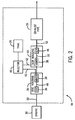
- FIG. 2 is a schematic diagram of an embodiment of an exhaust system 14 that may be used within the off-road work vehicle of FIG. 1 .
- an engine 30 expels exhaust 32 to the exhaust system 14.
- the illustrated embodiment of the exhaust system 14 includes a diesel oxidation catalyst (DOC) assembly having a housing 34 containing a DOC 36 and a mixer 38.
- the exhaust system 14 also includes an injector 40 for injecting diesel exhaust fluid (DEF) 42, a selective catalytic reduction (SCR) housing 44 containing an SCR module 46, and an exhaust pipe 54.
- the mixer 38 may be disposed within the SCR housing 44 instead of, or in addition to, the DOC housing 34.
- Certain embodiments of the exhaust system 14 may additionally include a diesel particulate filter to capture particulate matter, a muffler, or any other element suitable for use in an exhaust system.
- the DOC housing 34 receives exhaust 32, and directs the exhaust 32 into the DOC 36.
- the DOC 36 receives the exhaust and catalyzes the oxidization of carbon monoxide to carbon dioxide by using excess oxygen in the exhaust 32.
- the DOC 36 uses excess oxygen to catalyze the conversion of hydrocarbons to water and carbon dioxide.
- the DOC 36 may use ceramics, metals (e.g., platinum, palladium, etc.), or other suitable catalysts to catalyze the oxidization of the hydrocarbons and carbon monoxide molecules.
- the DOC 36 receives raw exhaust 32 and outputs catalyzed exhaust 48 with reduced concentrations of hydrocarbons and carbon monoxide.
- the DOC housing 34 directs the exhaust 48 to the mixer 38, which is enclosed within the DOC housing 34.
- the mixer 38 also receives the diesel exhaust fluid 42 from the injector 40, in addition to the exhaust 48 from the DOC 36.
- the exhaust system 14 includes a diesel exhaust fluid tank 26 for containing the diesel exhaust fluid 42, and supplying the diesel exhaust fluid to the injector 40.
- the injector 40 may include a diesel exhaust fluid tank 26 containing diesel exhaust fluid 42.
- the diesel exhaust fluid tank 26 containing the diesel exhaust fluid 42 may be remote from the injector 40.
- the mixer 38 may be disposed within the SCR housing 44, a separate housing, or any other housing suitable for containing the mixer 38.
- the injector 40 sprays the diesel exhaust fluid 42 into the exhaust 48 within the mixer 38.
- the diesel exhaust fluid 42 is a solution used to reduce NOx within the exhaust 48.
- the diesel exhaust fluid 42 may be an aqueous urea solution which undergoes thermal decomposition and hydrolysis within the exhaust system 14 to produce ammonia, which the SCR uses to convert the NOx into nitrogen and water.
- the mixer 38 supplies well-mixed exhaust solution 50 to the SCR module 46.
- the SCR module 46 receives the exhaust solution 50 and uses the distributed diesel exhaust fluid 42 to reduce the NOx concentration in the exhaust gas.
- the SCR module 46 sends processed exhaust 52 with a reduced NOx concentration through the exhaust pipe 54 to be released into the atmosphere.
- FIG. 3 is a perspective view of an embodiment of a diesel exhaust fluid tank, showing a diesel exhaust fluid bundle channel 56, electrical conduit channels 58, a supply module recess 60, a channel for a retaining bar 62, drains channels 64, metal inserts 66, and an electrical distribution center recess 68.
- the diesel exhaust fluid tank 26 may be molded from a single piece of polyethylene. However, it should be appreciated that the diesel exhaust fluid tank 26 may be molded from other types of thermoplastics such as polypropylene, polystyrene, polyvinyl chloride, or polytetrafluoroethylene in alternative embodiments.
- features such as, the diesel exhaust fluid bundle channel 56, electrical conduit channels 58, the supply module recess 60, the channel 62 for the retaining bar, the drain channels 64, and the metal inserts 66 may be molded into the diesel exhaust fluid tank 26 during the manufacturing process.
- the diesel exhaust fluid bundle channel 56 is configured to guide a diesel exhaust fluid bundle.
- the electrical conduit channels 58 are configured to guide electrical conduits.
- the depth of the conduit channels is selected to create a vertical gap between the diesel exhaust fluid bundle and the electrical conduit, and between a first electrical conduit and a second electrical conduit at an intersection of the conduits. Accordingly, the possibility of contact between the conduits is substantially reduced or eliminated, thereby reducing wear on the conduits.
- the supply module recess 60 is configured to receive a diesel exhaust fluid supply module.
- the channel 62 is configured to interface with a retaining rod.
- the drain channels 64 are configured to provide structural support to the diesel exhaust fluid tank and to enable diesel exhaust fluid to flow downwardly through the drain channels without contacting the retaining bar.
- the metal inserts 66 may be threaded and configured to interface with a bolt or a cap.
- the electrical distribution center recess 68 is configured to receive an electrical distribution center.
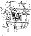
- FIG. 4 is a perspective view of the diesel exhaust fluid tank of FIG. 3 , showing the diesel exhaust fluid bundle 70, a supply module 72, a retaining bar 74, and drain channels 64.
- the diesel exhaust fluid bundle 70 is guided by the diesel exhaust fluid bundle channel 56.
- the diesel exhaust fluid bundle channel 56 includes a curve 76.
- the curve 76 in the diesel exhaust fluid bundle channel 56 may be used to guide the diesel exhaust fluid bundle 70 around other structures, such as an electrical conduit.
- the curve 76 in the diesel exhaust fluid bundle channel 56 may accommodate a maximum desired curvature of the diesel exhaust fluid bundle 70, thereby reducing strain on the diesel exhaust fluid bundle 70.
- the diesel exhaust fluid bundle 70 is secured to the diesel exhaust fluid tank 26 with clamps, such as the illustrated p-clamps 78. It may be observed that a diesel exhaust fluid bundle 70 having a tighter bend may utilize more p-clamps 78. On the other hand, when the bend is more gradual, fewer p-clamps 78 may be used. Thus, a more gradual curve 76 may also reduce the part count. It should be appreciated that the diesel exhaust fluid bundle channel 56 may be formed into any shape suitable for molding polyethylene. In addition, the illustrated diesel exhaust fluid bundle 70 interfaces with both the supply module 72 and the diesel exhaust fluid tank 26.
- the diesel exhaust fluid bundle 70 passes over one of the electrical conduit channels 58.
- an electrical conduit may pass under the diesel exhaust fluid bundle 70 without rubbing and/or chaffing, thereby reducing wear on the conduits.
- the retaining bar 74 is configured to support the diesel exhaust fluid tank 26. It should be appreciated that the retaining bar may be formed from any suitable material, such as stainless steel, that is capable of holding the diesel exhaust fluid tank 26 in place and supporting the weight of the diesel exhaust fluid tank 26 and the diesel exhaust fluid. In the depicted embodiment, the retaining bar 74 extends partially around the diesel exhaust fluid tank 26, and includes mounts for securing the tank to other structures of the off-road vehicle 10. In addition, the retaining bar 74 interfaces with the channel 62 molded into the diesel exhaust fluid tank 26. In the depicted embodiment, the channel 62 partially surrounds the retaining bar 74, thereby enabling the retaining bar to support the diesel exhaust fluid tank 26 in both vertical and horizontal directions.
- the drain channels 64 are configured to enable diesel exhaust fluid to flow downwardly through the drain channels 64.
- the drain channels 64 are substantially vertical and located in areas of the diesel exhaust fluid tank 26 that may receive spilled and/or leaked diesel exhaust fluid (e.g. under the supply module 72 and under the neck filler 81). Once diesel exhaust fluid enters the drain channels 64, gravity pulls the fluid downwardly toward the ground.
- the drain channels 64 are recessed into the diesel exhaust fluid tank 26, as shown, which may reduce the possibility of contact between diesel exhaust fluid and other structures in the vehicle 10.
- the channel 62 crosses the drain channels 64 at multiple locations. The retaining bar is spaced from the base of the channels 64, thereby reducing the possibility of contact between the diesel exhaust fluid and the retaining bar.
- the drain channels 64 are configured to provide additional structural support to the diesel exhaust fluid tank 26.
- the diesel exhaust fluid tank 26 may hold a significant amount of diesel exhaust fluid (e.g. 230L) and may be made out of polyethylene, which is resilient.
- walls 80 of the drain channels 64 support the tank without substantially increasing weight.
- the drain channel walls 80 are substantially perpendicular to the exterior surface of the diesel exhaust fluid tank 26.
- the structural rigidity of the tank may be enhanced.
- the drain channel walls 80 may reduce the horizontal deformation, which may otherwise be induced by the weight of the diesel exhaust fluid.
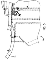
- FIG. 5 is a cross-sectional view of the diesel exhaust fluid tank of FIG. 3 , showing the routing of a diesel exhaust fluid bundle 70.
- the diesel exhaust fluid bundle channel 56 includes a sloped portion 82. Similar to the curve 76 in FIG. 4 , the sloped portion 82 guides the diesel exhaust fluid bundle 70 around other structures such as an electrical conduit. As illustrated, the diesel exhaust fluid bundle channel 56 and the corresponding diesel exhaust fluid bundle 70 may be recessed into an exterior surface of the diesel exhaust fluid tank 26. Again, it may be beneficial to limit the slope of the diesel exhaust fluid bundle channel 56 to reduce strain on the diesel exhaust fluid bundle 70.
- FIG. 6 is a perspective view of the diesel exhaust fluid tank of FIG. 3 , showing the diesel exhaust fluid bundle 70, electrical conduits 84, the supply module 72, an electrical distribution center 86, and the retaining bar 74.
- the supply module 72 is mounted within the supply module recess 60
- the electrical distribution center 86 is mounted within the electrical distribution recess 68.
- the diesel exhaust fluid tank 26 may utilize the supply module recess 60 and the electrical distribution recess 68 reduce the protrusion of the supply module 72 and the electrical distribution center 86 from the diesel exhaust fluid tank 26, which may provide a more efficient use of the limited space within the vehicle 10.
- the size of the diesel exhaust fluid tank 26 may be increased without contacting other structures within the vehicle 10.
- the electrical distribution center 86 is connected to the electrical conduits 84.
- the electrical conduits facilitate communication between the electrical distribution center and other parts of the vehicle 10.
- the supply module 72 includes a filter 88, which may be removable from the supply module 72. In the depicted embodiment, the filter 88 is not blocked by any portion of the tank structure, and may be removed while the supply module 72 is mounted to the diesel exhaust fluid tank 26.
- the diesel exhaust fluid bundle 70 and the electrical conduits 84 cross one another without rubbing and/or chaffing because a vertical gap is formed between them.
- the electrical conduit channels 58 may include any of the features (e.g. the curve 76 and the slope 82) described above in relation to the diesel exhaust fluid bundle channel 56.
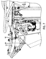
- FIG. 7 is a cross-sectional view of the diesel exhaust fluid tank 26 of FIG. 3 , showing a gap 90 between a diesel exhaust fluid bundle 70 and an electrical conduit 84.
- the diesel exhaust fluid bundle 70 and the electrical conduit 84 may be guided by the diesel exhaust fluid bundle channel 56 and the electrical conduit channels 58 respectively, to avoid other structures in the vehicle, such as the access door shown in FIG. 8 .
- FIG. 8 is a side view of the diesel exhaust fluid tank of FIG. 3 , showing a gap 91 between an access door 92 and the diesel exhaust fluid bundle 70.
- the diesel exhaust fluid bundle channel 56, the electrical conduit channels 58, the supply module recess 60 and the electrical distribution recess 68 are configured to create the gap 91 between respective structure on the tank and other structures in the vehicle 10, such as surrounding electrical components.
- FIG. 9 is a side view of the diesel exhaust fluid tank 26 of FIG. 3 , showing the supply module recess 60, isolation mount recesses 93, sloped walls 94, and a drain channel 64.
- the supply module recess 60 is configured to receive the supply module 72.
- the supply module recess 93 may include one or more isolation mount recesses 93.
- the isolation mount recesses 93 are recessed into the exterior surface of the diesel exhaust fluid tank 26 and are configured to interface with one or more isolation mounts on the supply module.
- three isolation mounts are attached to the back of the supply module 72. These mounts interface with the three isolation mount recesses 93 in the diesel exhaust fluid tank 26.
- the isolation mounts are configured to isolate the supply module 72 from the diesel exhaust fluid tank 26. Accordingly, the isolation mounts may be made out of a resilient substance, such as rubber.
- the drain channel 64 may be located in areas of the tank that may receive spilled and/or leaked diesel exhaust fluid, such as under the supply module 72.
- the drain channel 64 is configured to guide diesel exhaust fluid downwardly through the drain channel 64.
- sloped walls 94 are molded into the exterior surface of the diesel exhaust fluid tank 26, and are configured to capture and funnel the diesel exhaust fluid into the drain channels 64. As illustrated, the sloped walls 94 extend to the drain channel 64 and slope inwardly toward the drain channel 64.
- FIG. 10 is a cross-sectional view of the diesel exhaust fluid tank 26 of FIG. 3 , showing the sloped walls 94 and the isolation mount recesses 93. As shown, the sloped walls 94 are angled upwardly. In addition to being sloped inwardly toward the drain channel 64, the sloped walls 94 may also be angled upwardly to increase the amount of diesel exhaust fluid funneled into the drain channel 64. For example, in the depicted embodiment, the sloped walls 94 may reduce the possibility of the diesel exhaust fluid flowing over the edge 96 of the sloped wall 94 and away from the drain channel 64. The illustrated cross-sectional view also shows the isolation mount recesses 93 recessed into the diesel exhaust fluid tank 26.
- FIG. 11 is a perspective view of the diesel exhaust fluid tank 26 of FIG. 3 , showing a metal insert 66 and a clamp recess 98.
- the metal insert 66 may be molded into the diesel exhaust fluid tank 26.
- the metal insert 66 may be flush or slightly above the surface of the diesel exhaust fluid tank 26.
- the metal insert 66 is threaded and configured to interface with a bolt.
- a p-clamp 78 such as the ones shown in FIG. 4 , may be used to secure a conduit, such as the diesel exhaust fluid bundle 70 to the tank 26.
- the p-clamp 78 fits into the clamp recess 98 and is secured to the tank by a bolt that engages the metal insert 66. Accordingly, the p-clamp secures the diesel exhaust fluid bundle 70 to the tank.
- FIG. 12 is a side view of the diesel exhaust fluid tank 26 of FIG. 3 , showing the neck filler 81, sloped walls 94, and the drain channel 64.
- the neck filler 81 includes a metal insert 66 molded into an exterior surface of the diesel exhaust fluid tank 26.
- the neck filler 81 is configured to enable an operator to fill the diesel exhaust fluid tank 26 with diesel exhaust fluid.
- sloped walls 94 and the drain channel 64 are located under the neck filler 81 to capture, funnel, and guide diesel exhaust fluid downwardly to the ground.
- the neck filler 81 is configured to interface with a cap to substantially seal the diesel exhaust fluid within the tank.
- the drain channels 64 may cross the channel 62 and the retaining bar 74.
- FIG. 13 is a top view of the diesel exhaust fluid tank 26 of FIG. 3 , showing drain channels 64 that reduce the possibility of the diesel exhaust fluid contacting the retaining bar 74.
- the diesel exhaust fluid tank 26 includes a cutout formed within the retaining bar channel 62, in which the cutout establishes a gap 100 between the retaining bar 74 and a body of the diesel exhaust fluid tank 26.
- the gap 100 is configured to enable diesel exhaust fluid flow downwardly into the drain channel without contacting the retaining bar 74.
- FIG. 14 is a perspective view of an alternate embodiment of a diesel exhaust fluid tank 26.
- the alternate embodiment of the diesel exhaust fluid tank 26 includes the diesel exhaust fluid bundle channel 56, the electrical conduit channels 58, the supply module recess 60, the channel 62, the drain channels 64, the metal inserts 66, the electrical distribution center recess 68, isolation mount recesses 93, and sloped walls 94.
- the electrical conduit channels include a sloped portion 102.
- the electrical conduit channels 58 includes a large radius curve 104 that limits bending of the electrical conduit 84 as it interfaces with a fuse, a relay, and/or a switch, which may reduce the strain on the electrical conduit 84.
- diesel exhaust fluid tank 26 has many of the same features as the diesel exhaust fluid tank 26 depicted in FIG. 3 , the shape of the diesel exhaust fluid tank 26 overall and the features may be different. Thus, the diesel exhaust fluid tank 26 described herein may be adapted to fit any suitable off-road vehicle.
Landscapes
- Engineering & Computer Science (AREA)
- Chemical & Material Sciences (AREA)
- Mechanical Engineering (AREA)
- Combustion & Propulsion (AREA)
- Chemical Kinetics & Catalysis (AREA)
- General Engineering & Computer Science (AREA)
- Health & Medical Sciences (AREA)
- Toxicology (AREA)
- Transportation (AREA)
- Exhaust Gas After Treatment (AREA)
Description
- The present disclosure relates generally to off-road vehicles with diesel engines, and more particularly, a diesel exhaust fluid tank for an off-road vehicle.
- Certain off-road vehicles are powered by diesel engines and produce exhaust gas. The exhaust gas may include undesirable byproducts, such as nitrogen oxides (NOx), carbon monoxide, and particulate material. Traditional exhaust systems may spray a diesel exhaust fluid (DEF) into the flow of exhaust to reduce emissions. New government regulations have continually reduced the amount of acceptable concentrations of byproducts dispelled from off-road vehicles, particularly in relation to NOx. Thus, additional diesel exhaust fluid may be mixed with the exhaust to further reduce emissions. Therefore, the amount of diesel exhaust fluid carried on a diesel off-road vehicle may also be increased. Unfortunately, certain off-road vehicles may not have sufficient internal space to accommodate larger diesel exhaust fluid tanks. Such a tank is known from
JP 2011 132890 - Certain embodiments commensurate in scope with the originally claimed invention are summarized below. These embodiments are not intended to limit the scope of the claimed invention, but rather these embodiments are intended only to provide a brief summary of possible forms of the invention. Indeed, the invention may encompass a variety of forms that may be similar to or different from the embodiments set forth below.
- In a first embodiment, a diesel exhaust fluid (DEF) tank for an off-road vehicle includes a first conduit channel molded into an exterior surface of the diesel exhaust fluid tank, at a first depth, in which the first conduit channel is configured to guide a first conduit along the exterior surface of the diesel exhaust fluid tank. The diesel exhaust fluid tank further includes a second conduit channel molded into the exterior surface of the diesel exhaust fluid tank at a second depth, different than the first depth, in which the second conduit channel is configured to guide a second conduit, and the first depth and the second depth are selected to create a vertical gap between the first conduit and the second conduit at an intersection of the conduits.
- In a second embodiment, a diesel exhaust fluid (DEF) tank for an off-road vehicle includes a drain channel molded into an exterior surface of the diesel exhaust fluid tank, in which the drain channel is configured to provide structural support to the diesel exhaust fluid tank and to enable diesel exhaust fluid to flow downwardly through the drain channel. The diesel exhaust fluid tank further includes a sloped wall molded into the exterior surface of the diesel exhaust fluid tank, in which the sloped wall is configured to capture and funnel the diesel exhaust fluid into the drain channel.
- In a third embodiment, a diesel exhaust fluid (DEF) tank for an off-road vehicle includes a retaining bar configured to support the diesel exhaust fluid tank, a channel molded into a side of the diesel exhaust fluid tank, in which the channel is configured to interface with the retaining rod; and a cutout formed within the channel, in which the cutout establishes a gap between the retaining bar and a body of the diesel exhaust fluid tank. The diesel exhaust fluid tank further includes a drain channel molded into an exterior surface of the diesel exhaust fluid tank, in which the drain channel is configured to provide structural support to the diesel exhaust fluid tank, and the gap is configured to enable diesel exhaust fluid flow downwardly into the drain channel without contacting the retaining bar.
- These and other features, aspects, and advantages of the present invention will become better understood when the following detailed description is read with reference to the accompanying drawings in which like characters represent like parts throughout the drawings, wherein:
-
FIG. 1 is a perspective view of an embodiment of an off-road work vehicle that employs an exhaust system. -
FIG. 2 is a schematic diagram of an embodiment of an exhaust system that may be used within the off-road work vehicle ofFIG. 1 . -
FIG. 3 is a perspective view of an embodiment of a diesel exhaust fluid tank, showing a diesel exhaust fluid bundle channel, electrical conduit channels, a supply module recess, a channel for a retaining bar, drain channels, metal inserts, and an electrical distribution center recess. -
FIG. 4 is a perspective view of the diesel exhaust fluid tank ofFIG. 3 , showing a diesel exhaust fluid bundle, a supply module, and a retaining bar. -
FIG. 5 is a cross-sectional view of the diesel exhaust fluid tank ofFIG. 3 , showing the routing of a diesel exhaust fluid bundle. -
FIG. 6 is a perspective view of the diesel exhaust fluid tank ofFIG. 3 , showing a diesel exhaust fluid bundle, electrical conduits, a supply module, an electrical distribution center, and a retaining bar. -
FIG. 7 is a cross-sectional view of the diesel exhaust fluid tank ofFIG. 3 , showing a gap between a diesel exhaust fluid bundle and electrical conduits. -
FIG. 8 is a side view of the diesel exhaust fluid tank ofFIG. 3 , showing a gap between an access door and a diesel exhaust fluid bundle. -
FIG. 9 is a side view of the diesel exhaust fluid tank ofFIG. 3 , showing a supply module recess, isolation mount recesses, sloped walls, and a drain channel. -
FIG. 10 is a cross-sectional view of the diesel exhaust fluid tank ofFIG. 3 , showing the sloped walls. -
FIG. 11 is a perspective view of the diesel exhaust fluid tank ofFIG. 3 , showing a metal insert and a recess for a clamp. -
FIG. 12 is a side view of the diesel exhaust fluid tank ofFIG. 3 , showing a neck filler, sloped walls, and a drain channel. -
FIG. 13 is a top view of the diesel exhaust fluid tank ofFIG. 3 , showing gaps between a retaining bar and a body of the diesel exhaust fluid tank. -
FIG. 14 is a perspective view of an alternate embodiment of a diesel exhaust fluid tank. - One or more specific embodiments of the present disclosure will be described below. In an effort to provide a concise description of these embodiments, all features of an actual implementation may not be described in the specification. It should be appreciated that in the development of any such actual implementation, as in any engineering or design project, numerous implementation-specific decisions must be made to achieve the developers' specific goals, such as compliance with system-related and business-related constraints, which may vary from one implementation to another. Moreover, it should be appreciated that such a development effort might be complex and time consuming, but would nevertheless be a routine undertaking of design, fabrication, and manufacture for those of ordinary skill having the benefit of this disclosure.
- When introducing elements of various embodiments of the present disclosure, the articles "a," "an," "the," and "said" are intended to mean that there are one or more of the elements. The terms "comprising," "including," and "having" are intended to be inclusive and mean that there may be additional elements other than the listed elements. Any examples of operating parameters and/or environmental conditions are not exclusive of other parameters/conditions of the disclosed embodiments.
- Various embodiments of the present disclosure include an exhaust system for a diesel engine of an off-road vehicle. As regulations regarding exhaust continue to become more stringent regarding the concentration of expelled byproducts (e.g., nitrogen oxides), the amount of diesel exhaust fluid (DEF) used by the off-road vehicle may increase. To account for the additional diesel exhaust fluid, larger diesel exhaust fluid tanks may be added to existing off-road vehicles. In certain embodiments, the tank size may increase significantly (e.g. from 160L to 230L). However, the structure surrounding the tank may not be able to accommodate the larger tank. For example, a diesel exhaust fluid bundle and electrical conduits be routed above and around the tank; however, a larger diesel exhaust fluid tank, may interfere with passage of these conduits. In other words, there is less room for the diesel exhaust fluid bundle and the electrical conduits to pass above and around the tank. Thus, rubbing and/or chaffing may occur between the diesel exhaust fluid bundle and the electrical conduits. Other structures may also limit the size of the tank, such as a supply module, an electrical distribution center, and an access door.
- In addition, with a larger diesel exhaust fluid tank, more structural support may be beneficial. Certain diesel exhaust fluid tanks are manufactured from a single piece of polyethylene. Accordingly, with the increase in tank size, the diesel exhaust fluid tank may be more susceptible to deformation during both assembly of the off-road vehicle and while filling the diesel exhaust fluid tank with diesel exhaust fluid. Furthermore, diesel exhaust fluid may interfere with other structures of the off-road vehicle. With less open space around the diesel exhaust fluid tank, it may be more difficult to properly drain leaking fluid.
- Accordingly, one embodiment provides a diesel exhaust fluid (DEF) tank for an off-road vehicle including a first conduit channel molded into an exterior surface of the diesel exhaust fluid tank, at a first depth, in which the first conduit channel is configured to guide a first conduit along the exterior surface of the diesel exhaust fluid tank. The diesel exhaust fluid tank further includes a second conduit channel molded into the exterior surface of the diesel exhaust fluid tank at a second depth, different than the first depth, in which the second conduit channel is configured to guide a second conduit, and the first depth and the second depth are selected to create a vertical gap between the first conduit and the second conduit at an intersection of the conduits.
- Another embodiment provides a diesel exhaust fluid (DEF) tank for an off-road vehicle including a drain channel molded into an exterior surface of the diesel exhaust fluid tank, in which the drain channel is configured to provide structural support to the diesel exhaust fluid tank and to enable diesel exhaust fluid to flow downwardly through the drain channel. The diesel exhaust fluid tank further includes a sloped wall molded into the exterior surface of the diesel exhaust fluid tank, in which the sloped wall is configured to capture and funnel the diesel exhaust fluid into the drain channel. Accordingly, the drain channels serve a dual purpose of providing structural rigidity to the diesel exhaust fluid tank and enabling leaking and/or spilled diesel exhaust fluid to flow toward the ground.
- With the forgoing in mind, it may be useful to describe a diesel exhaust fluid tank incorporating the techniques disclosed herein. Accordingly,
FIG. 1 is a perspective view of an embodiment of anagricultural work vehicle 10 that employs an exhaust system for a diesel engine. In certain embodiments, theagricultural work vehicle 10 may be a tractor, off-road vehicle, work vehicle, or any other suitable vehicle that may incorporate an exhaust system for a diesel engine. The illustratedvehicle 10 has abody 12 that houses an engine, transmission, cooling system, and power train (not separately shown). Thebody 12 also houses a portion of anexhaust system 14. Further, theagricultural work vehicle 10 has acabin 16 where an operator may sit or stand to operate thevehicle 10. Thevehicle 10 has fourfront wheels 18 and fourrear wheels 20 that rotate to move thevehicle 10. Alternatively, thevehicle 10 may have two or sixfront wheels 18 andrear wheels 20. In addition, thevehicle 10 may be a two track or a fourtrack vehicle 10. As will be appreciated, thevehicle 10 is maneuvered using asteering wheel 22 that induces the vehicle to bend about a pivot joint 23. As illustrated, thewheels 18 are coupled to an axle 24 (e.g., fixed or suspended) that supports thewheels 18, and facilitates wheel rotation. As discussed in detail below, theexhaust system 14 may be routed around various systems within thebody 12, such as a dieselexhaust fluid tank 26 located behind an access door. -
FIG. 2 is a schematic diagram of an embodiment of anexhaust system 14 that may be used within the off-road work vehicle ofFIG. 1 . In the illustrated embodiment, anengine 30 expelsexhaust 32 to theexhaust system 14. The illustrated embodiment of theexhaust system 14 includes a diesel oxidation catalyst (DOC) assembly having ahousing 34 containing aDOC 36 and amixer 38. Theexhaust system 14 also includes aninjector 40 for injecting diesel exhaust fluid (DEF) 42, a selective catalytic reduction (SCR)housing 44 containing anSCR module 46, and anexhaust pipe 54. In some embodiments, themixer 38 may be disposed within theSCR housing 44 instead of, or in addition to, theDOC housing 34. Certain embodiments of theexhaust system 14 may additionally include a diesel particulate filter to capture particulate matter, a muffler, or any other element suitable for use in an exhaust system. - The
DOC housing 34 receivesexhaust 32, and directs theexhaust 32 into theDOC 36. TheDOC 36 receives the exhaust and catalyzes the oxidization of carbon monoxide to carbon dioxide by using excess oxygen in theexhaust 32. Similarly, theDOC 36 uses excess oxygen to catalyze the conversion of hydrocarbons to water and carbon dioxide. In certain embodiments, theDOC 36 may use ceramics, metals (e.g., platinum, palladium, etc.), or other suitable catalysts to catalyze the oxidization of the hydrocarbons and carbon monoxide molecules. Thus, theDOC 36 receivesraw exhaust 32 and outputs catalyzedexhaust 48 with reduced concentrations of hydrocarbons and carbon monoxide. TheDOC housing 34 directs theexhaust 48 to themixer 38, which is enclosed within theDOC housing 34. Themixer 38 also receives thediesel exhaust fluid 42 from theinjector 40, in addition to theexhaust 48 from theDOC 36. In certain embodiments, theexhaust system 14 includes a dieselexhaust fluid tank 26 for containing thediesel exhaust fluid 42, and supplying the diesel exhaust fluid to theinjector 40. Alternatively, theinjector 40 may include a dieselexhaust fluid tank 26 containingdiesel exhaust fluid 42. In further embodiments, the dieselexhaust fluid tank 26 containing thediesel exhaust fluid 42 may be remote from theinjector 40. In certain embodiments, themixer 38 may be disposed within theSCR housing 44, a separate housing, or any other housing suitable for containing themixer 38. - The
injector 40 sprays thediesel exhaust fluid 42 into theexhaust 48 within themixer 38. Thediesel exhaust fluid 42 is a solution used to reduce NOx within theexhaust 48. For example, in certain embodiments, thediesel exhaust fluid 42 may be an aqueous urea solution which undergoes thermal decomposition and hydrolysis within theexhaust system 14 to produce ammonia, which the SCR uses to convert the NOx into nitrogen and water. Thus, themixer 38 supplies well-mixedexhaust solution 50 to theSCR module 46. TheSCR module 46 receives theexhaust solution 50 and uses the distributeddiesel exhaust fluid 42 to reduce the NOx concentration in the exhaust gas. Finally, theSCR module 46 sends processedexhaust 52 with a reduced NOx concentration through theexhaust pipe 54 to be released into the atmosphere. -
FIG. 3 is a perspective view of an embodiment of a diesel exhaust fluid tank, showing a diesel exhaustfluid bundle channel 56,electrical conduit channels 58, asupply module recess 60, a channel for a retainingbar 62, drainschannels 64, metal inserts 66, and an electricaldistribution center recess 68. The dieselexhaust fluid tank 26 may be molded from a single piece of polyethylene. However, it should be appreciated that the dieselexhaust fluid tank 26 may be molded from other types of thermoplastics such as polypropylene, polystyrene, polyvinyl chloride, or polytetrafluoroethylene in alternative embodiments. In the illustrated embodiment, features such as, the diesel exhaustfluid bundle channel 56,electrical conduit channels 58, thesupply module recess 60, thechannel 62 for the retaining bar, thedrain channels 64, and the metal inserts 66 may be molded into the dieselexhaust fluid tank 26 during the manufacturing process. - The diesel exhaust
fluid bundle channel 56 is configured to guide a diesel exhaust fluid bundle. Similarly, theelectrical conduit channels 58 are configured to guide electrical conduits. The depth of the conduit channels is selected to create a vertical gap between the diesel exhaust fluid bundle and the electrical conduit, and between a first electrical conduit and a second electrical conduit at an intersection of the conduits. Accordingly, the possibility of contact between the conduits is substantially reduced or eliminated, thereby reducing wear on the conduits. - The
supply module recess 60 is configured to receive a diesel exhaust fluid supply module. Thechannel 62 is configured to interface with a retaining rod. Thedrain channels 64 are configured to provide structural support to the diesel exhaust fluid tank and to enable diesel exhaust fluid to flow downwardly through the drain channels without contacting the retaining bar. The metal inserts 66 may be threaded and configured to interface with a bolt or a cap. The electricaldistribution center recess 68 is configured to receive an electrical distribution center. -
FIG. 4 is a perspective view of the diesel exhaust fluid tank ofFIG. 3 , showing the dieselexhaust fluid bundle 70, asupply module 72, a retainingbar 74, and drainchannels 64. As illustrated, the dieselexhaust fluid bundle 70 is guided by the diesel exhaustfluid bundle channel 56. In the illustrated embodiment, the diesel exhaustfluid bundle channel 56 includes acurve 76. Thus, because the diesel exhaustfluid bundle channel 56 is curved, the dieselexhaust fluid bundle 70 guided by the channel is also curved. Thecurve 76 in the diesel exhaustfluid bundle channel 56 may be used to guide the dieselexhaust fluid bundle 70 around other structures, such as an electrical conduit. Furthermore, thecurve 76 in the diesel exhaustfluid bundle channel 56 may accommodate a maximum desired curvature of the dieselexhaust fluid bundle 70, thereby reducing strain on the dieselexhaust fluid bundle 70. In addition, as illustrated, the dieselexhaust fluid bundle 70 is secured to the dieselexhaust fluid tank 26 with clamps, such as the illustrated p-clamps 78. It may be observed that a dieselexhaust fluid bundle 70 having a tighter bend may utilize more p-clamps 78. On the other hand, when the bend is more gradual, fewer p-clamps 78 may be used. Thus, a moregradual curve 76 may also reduce the part count. It should be appreciated that the diesel exhaustfluid bundle channel 56 may be formed into any shape suitable for molding polyethylene. In addition, the illustrated dieselexhaust fluid bundle 70 interfaces with both thesupply module 72 and the dieselexhaust fluid tank 26. - As can be seen in the depicted embodiment, the diesel
exhaust fluid bundle 70 passes over one of theelectrical conduit channels 58. As will be described in more detail inFIG. 7 , an electrical conduit may pass under the dieselexhaust fluid bundle 70 without rubbing and/or chaffing, thereby reducing wear on the conduits. - The retaining
bar 74 is configured to support the dieselexhaust fluid tank 26. It should be appreciated that the retaining bar may be formed from any suitable material, such as stainless steel, that is capable of holding the dieselexhaust fluid tank 26 in place and supporting the weight of the dieselexhaust fluid tank 26 and the diesel exhaust fluid. In the depicted embodiment, the retainingbar 74 extends partially around the dieselexhaust fluid tank 26, and includes mounts for securing the tank to other structures of the off-road vehicle 10. In addition, the retainingbar 74 interfaces with thechannel 62 molded into the dieselexhaust fluid tank 26. In the depicted embodiment, thechannel 62 partially surrounds the retainingbar 74, thereby enabling the retaining bar to support the dieselexhaust fluid tank 26 in both vertical and horizontal directions. - The
drain channels 64 are configured to enable diesel exhaust fluid to flow downwardly through thedrain channels 64. In the illustrated embodiment, thedrain channels 64 are substantially vertical and located in areas of the dieselexhaust fluid tank 26 that may receive spilled and/or leaked diesel exhaust fluid (e.g. under thesupply module 72 and under the neck filler 81). Once diesel exhaust fluid enters thedrain channels 64, gravity pulls the fluid downwardly toward the ground. Furthermore, thedrain channels 64 are recessed into the dieselexhaust fluid tank 26, as shown, which may reduce the possibility of contact between diesel exhaust fluid and other structures in thevehicle 10. In addition, in the depicted embodiment, thechannel 62 crosses thedrain channels 64 at multiple locations. The retaining bar is spaced from the base of thechannels 64, thereby reducing the possibility of contact between the diesel exhaust fluid and the retaining bar. - In addition, the
drain channels 64 are configured to provide additional structural support to the dieselexhaust fluid tank 26. As described above, the dieselexhaust fluid tank 26 may hold a significant amount of diesel exhaust fluid (e.g. 230L) and may be made out of polyethylene, which is resilient. Accordingly,walls 80 of thedrain channels 64 support the tank without substantially increasing weight. For example, in the depicted embodiment, thedrain channel walls 80 are substantially perpendicular to the exterior surface of the dieselexhaust fluid tank 26. As a result, the structural rigidity of the tank may be enhanced. Working in conjunction with the retainingbar 74, thedrain channel walls 80 may reduce the horizontal deformation, which may otherwise be induced by the weight of the diesel exhaust fluid. -
FIG. 5 is a cross-sectional view of the diesel exhaust fluid tank ofFIG. 3 , showing the routing of a dieselexhaust fluid bundle 70. In the depicted embodiment, the diesel exhaustfluid bundle channel 56 includes a slopedportion 82. Similar to thecurve 76 inFIG. 4 , the slopedportion 82 guides the dieselexhaust fluid bundle 70 around other structures such as an electrical conduit. As illustrated, the diesel exhaustfluid bundle channel 56 and the corresponding dieselexhaust fluid bundle 70 may be recessed into an exterior surface of the dieselexhaust fluid tank 26. Again, it may be beneficial to limit the slope of the diesel exhaustfluid bundle channel 56 to reduce strain on the dieselexhaust fluid bundle 70. -
FIG. 6 is a perspective view of the diesel exhaust fluid tank ofFIG. 3 , showing the dieselexhaust fluid bundle 70,electrical conduits 84, thesupply module 72, anelectrical distribution center 86, and the retainingbar 74. As shown, thesupply module 72 is mounted within thesupply module recess 60, and theelectrical distribution center 86 is mounted within theelectrical distribution recess 68. The dieselexhaust fluid tank 26 may utilize thesupply module recess 60 and theelectrical distribution recess 68 reduce the protrusion of thesupply module 72 and theelectrical distribution center 86 from the dieselexhaust fluid tank 26, which may provide a more efficient use of the limited space within thevehicle 10. Thus, the size of the dieselexhaust fluid tank 26 may be increased without contacting other structures within thevehicle 10. - In the depicted embodiment, the
electrical distribution center 86 is connected to theelectrical conduits 84. The electrical conduits facilitate communication between the electrical distribution center and other parts of thevehicle 10. Furthermore, thesupply module 72 includes afilter 88, which may be removable from thesupply module 72. In the depicted embodiment, thefilter 88 is not blocked by any portion of the tank structure, and may be removed while thesupply module 72 is mounted to the dieselexhaust fluid tank 26. - As described above, the diesel
exhaust fluid bundle 70 and theelectrical conduits 84 cross one another without rubbing and/or chaffing because a vertical gap is formed between them. It should be appreciated that theelectrical conduit channels 58 may include any of the features (e.g. thecurve 76 and the slope 82) described above in relation to the diesel exhaustfluid bundle channel 56. -
FIG. 7 is a cross-sectional view of the dieselexhaust fluid tank 26 ofFIG. 3 , showing agap 90 between a dieselexhaust fluid bundle 70 and anelectrical conduit 84. In addition, the dieselexhaust fluid bundle 70 and theelectrical conduit 84 may be guided by the diesel exhaustfluid bundle channel 56 and theelectrical conduit channels 58 respectively, to avoid other structures in the vehicle, such as the access door shown inFIG. 8 . -
FIG. 8 is a side view of the diesel exhaust fluid tank ofFIG. 3 , showing agap 91 between anaccess door 92 and the dieselexhaust fluid bundle 70. Utilizing the techniques herein, the diesel exhaustfluid bundle channel 56, theelectrical conduit channels 58, thesupply module recess 60 and theelectrical distribution recess 68 are configured to create thegap 91 between respective structure on the tank and other structures in thevehicle 10, such as surrounding electrical components. -
FIG. 9 is a side view of the dieselexhaust fluid tank 26 ofFIG. 3 , showing thesupply module recess 60, isolation mount recesses 93, slopedwalls 94, and adrain channel 64. As described above, thesupply module recess 60 is configured to receive thesupply module 72. As depicted, thesupply module recess 93 may include one or more isolation mount recesses 93. The isolation mount recesses 93 are recessed into the exterior surface of the dieselexhaust fluid tank 26 and are configured to interface with one or more isolation mounts on the supply module. In the illustrated embodiment, three isolation mounts are attached to the back of thesupply module 72. These mounts interface with the three isolation mount recesses 93 in the dieselexhaust fluid tank 26. The isolation mounts are configured to isolate thesupply module 72 from the dieselexhaust fluid tank 26. Accordingly, the isolation mounts may be made out of a resilient substance, such as rubber. - As described above, the
drain channel 64 may be located in areas of the tank that may receive spilled and/or leaked diesel exhaust fluid, such as under thesupply module 72. Thedrain channel 64 is configured to guide diesel exhaust fluid downwardly through thedrain channel 64. To direct fluid into thedrain channel 64, slopedwalls 94 are molded into the exterior surface of the dieselexhaust fluid tank 26, and are configured to capture and funnel the diesel exhaust fluid into thedrain channels 64. As illustrated, the slopedwalls 94 extend to thedrain channel 64 and slope inwardly toward thedrain channel 64. -
FIG. 10 is a cross-sectional view of the dieselexhaust fluid tank 26 ofFIG. 3 , showing the slopedwalls 94 and the isolation mount recesses 93. As shown, the slopedwalls 94 are angled upwardly. In addition to being sloped inwardly toward thedrain channel 64, the slopedwalls 94 may also be angled upwardly to increase the amount of diesel exhaust fluid funneled into thedrain channel 64. For example, in the depicted embodiment, the slopedwalls 94 may reduce the possibility of the diesel exhaust fluid flowing over theedge 96 of the slopedwall 94 and away from thedrain channel 64. The illustrated cross-sectional view also shows the isolation mount recesses 93 recessed into the dieselexhaust fluid tank 26. -
FIG. 11 is a perspective view of the dieselexhaust fluid tank 26 ofFIG. 3 , showing ametal insert 66 and aclamp recess 98. As described above, themetal insert 66 may be molded into the dieselexhaust fluid tank 26. For example, themetal insert 66 may be flush or slightly above the surface of the dieselexhaust fluid tank 26. In the illustrated embodiment, themetal insert 66 is threaded and configured to interface with a bolt. Working in conjunction with theclamp recess 98, a p-clamp 78, such as the ones shown inFIG. 4 , may be used to secure a conduit, such as the dieselexhaust fluid bundle 70 to thetank 26. For example, in the depicted embodiment, the p-clamp 78 fits into theclamp recess 98 and is secured to the tank by a bolt that engages themetal insert 66. Accordingly, the p-clamp secures the dieselexhaust fluid bundle 70 to the tank. -
FIG. 12 is a side view of the dieselexhaust fluid tank 26 ofFIG. 3 , showing theneck filler 81, slopedwalls 94, and thedrain channel 64. In the depicted embodiment, theneck filler 81 includes ametal insert 66 molded into an exterior surface of the dieselexhaust fluid tank 26. Theneck filler 81 is configured to enable an operator to fill the dieselexhaust fluid tank 26 with diesel exhaust fluid. As described above, slopedwalls 94 and thedrain channel 64 are located under theneck filler 81 to capture, funnel, and guide diesel exhaust fluid downwardly to the ground. As will be appreciated, theneck filler 81 is configured to interface with a cap to substantially seal the diesel exhaust fluid within the tank. As previously discussed, thedrain channels 64 may cross thechannel 62 and the retainingbar 74. -
FIG. 13 is a top view of the dieselexhaust fluid tank 26 ofFIG. 3 , showingdrain channels 64 that reduce the possibility of the diesel exhaust fluid contacting the retainingbar 74. In the depicted embodiment, the dieselexhaust fluid tank 26 includes a cutout formed within the retainingbar channel 62, in which the cutout establishes agap 100 between the retainingbar 74 and a body of the dieselexhaust fluid tank 26. Thus, thegap 100 is configured to enable diesel exhaust fluid flow downwardly into the drain channel without contacting the retainingbar 74. -
FIG. 14 is a perspective view of an alternate embodiment of a dieselexhaust fluid tank 26. The alternate embodiment of the dieselexhaust fluid tank 26 includes the diesel exhaustfluid bundle channel 56, theelectrical conduit channels 58, thesupply module recess 60, thechannel 62, thedrain channels 64, the metal inserts 66, the electricaldistribution center recess 68, isolation mount recesses 93, and slopedwalls 94. As mentioned before, the electrical conduit channels include a slopedportion 102. In addition, in this embodiment, theelectrical conduit channels 58 includes alarge radius curve 104 that limits bending of theelectrical conduit 84 as it interfaces with a fuse, a relay, and/or a switch, which may reduce the strain on theelectrical conduit 84. Although the embodiment of the dieselexhaust fluid tank 26 has many of the same features as the dieselexhaust fluid tank 26 depicted inFIG. 3 , the shape of the dieselexhaust fluid tank 26 overall and the features may be different. Thus, the dieselexhaust fluid tank 26 described herein may be adapted to fit any suitable off-road vehicle. - This written description uses examples to disclose the invention, including the best mode, and also to enable any person skilled in the art to practice the invention, including making and using any devices or systems and performing any incorporated methods. The patentable scope of the invention is defined by the claims, and may include other examples that occur to those skilled in the art. Such other examples are intended to be within the scope of the claims if they have structural elements that do not differ from the literal language of the claims, or if they include equivalent structural elements with insubstantial differences from the literal language of the claims.
Claims (14)
- An exhaust system for an off-road vehicle (10) comprising a diesel exhaust fluid (DEF) tank (26), the diesel exhaust fluid tank (26) comprising:- a first conduit channel (56) molded into an exterior surface of the diesel exhaust fluid tank (26), at a first depth, wherein the first conduit channel (56) is configured to guide a first conduit (70) along the exterior surface of the diesel exhaust fluid tank (26); and- a second conduit channel (58) molded into the exterior surface of the diesel exhaust fluid tank (26) at a second depth, different than the first depth, wherein the second conduit channel (58) is configured to guide a second conduit (84), and characterized in that the first depth and the second depth are selected to create a vertical gap between the first conduit (70) and the second conduit (84) at an intersection of the conduits.
- The exhaust system of claim 1, wherein the first conduit (70) is a diesel exhaust fluid bundle (70) configured to extend between a supply module (72) and the diesel exhaust fluid tank (26).
- The exhaust system of claim 2 or 2, wherein the second conduit (84) is an electrical conduit (54) configured to interface with an electrical device (86) coupled to the diesel exhaust fluid tank (26).
- The exhaust system of claim 1 to 3, comprising a metal insert (66) molded into the diesel exhaust fluid tank (26), wherein the metal insert (66) is configured to facilitate coupling of an auxiliary component to the diesel exhaust fluid tank (26).
- The exhaust system of claim 4, comprising a recess (98) molded into the exterior surface of the diesel exhaust fluid tank (26), wherein the recess (98) is configured to accept a clamp (78), the metal insert is threaded and configured to interface with a bolt, the bolt is configured to secure the clamp (78) within the recess (98), and the clamp (78) is configured to secure the first conduit (70) within the first conduit channel (56) or the second conduit (84) within the second conduit channel (58).
- The exhaust system of claim 4, wherein the metal insert (66) comprises a fill neck (81) configured to enable the diesel exhaust fluid tank (26) to be filled with diesel exhaust fluid, and the sloped wall (94) is configured to capture the diesel exhaust fluid from the fill neck (81).
- The exhaust system according to any of the preceding claims, wherein the first conduit channel (56), the second channel (58), or a combination thereof, is sloped relative to the exterior surface of the diesel exhaust fluid tank (26).
- The exhaust system of claim 7, wherein the first conduit channel (56), the second conduit channel (58), or a combination thereof, is sloped to accommodate a maximum desired curvature of the first conduit (56), the second conduit (58), or a combination thereof.
- The exhaust system according to any of the preceding claims, wherein the first depth is selected to create a gap between the first conduit (70) and an access door (92) positioned adjacent to the diesel exhaust fluid tank (26), and the second depth is selected to create a gap between the second conduit (84) and the access door (92).
- The exhaust system of claim 9, comprising an electrical distribution center recess (68) molded into the exterior surface of the diesel exhaust fluid tank (26), wherein the electrical distribution center recess (68) is configured to receive an electrical distribution center (86), and a depth of the electrical distribution center recess (68) is selected to create a gap between the electrical distribution center (86) and the access door (92).
- The exhaust system according to any of the preceding claims further comprising:- a drain channel (64) molded into an exterior surface of the diesel exhaust fluid tank (26), wherein the drain channel (64) is configured to provide structural support to the diesel exhaust fluid tank (26) and to enable diesel exhaust fluid to flow downwardly through the drain channel (64); and- a sloped wall (94) molded into the exterior surface of the diesel exhaust fluid tank (26), wherein the sloped wall (94) is configured to capture and funnel the diesel exhaust fluid into the drain channel (64).
- The exhaust system of claim 11, comprising a diesel exhaust fluid supply module recess (60) molded into the exterior surface of the diesel exhaust fluid tank (26), wherein the diesel exhaust fluid supply module recess (60) is configured to receive a diesel exhaust fluid supply module, and the sloped wall (94) is configured to capture the diesel exhaust fluid from the diesel exhaust fluid supply module.
- The exhaust system of claim 11, wherein the diesel exhaust fluid supply module comprises at least one isolation mount , the supply module recess (60) comprises at least one isolation mount recess (93) molded into the exterior surface of the diesel exhaust fluid tank (26), and the at least one isolation mount recess (93) is configured to accept the at least one isolation mount.
- The exhaust system according to any of the preceding claims further comprising:- a retaining bar (74) configured to support the diesel exhaust fluid tank (26);- a channel (62) molded into a side of the diesel exhaust fluid tank (26), wherein the channel (62) is configured to interface with the retaining rod (74);- a cutout formed within the channel (62), wherein the cutout establishes a gap (100) between the retaining bar (74) and a body of the diesel exhaust fluid tank (26); and- a drain channel (64) molded into an exterior surface of the diesel exhaust fluid tank (26), wherein the drain channel (64) is configured to provide structural support to the diesel exhaust fluid tank (26), and the gap (100) is configured to enable diesel exhaust fluid flow downwardly into the drain channel (64) without contacting the retaining bar (74).
Applications Claiming Priority (1)
| Application Number | Priority Date | Filing Date | Title |
|---|---|---|---|
| US13/744,576 US9638085B2 (en) | 2013-01-18 | 2013-01-18 | Diesel exhaust fluid tank for an off-road vehicle |
Publications (2)
| Publication Number | Publication Date |
|---|---|
| EP2757232A1 EP2757232A1 (en) | 2014-07-23 |
| EP2757232B1 true EP2757232B1 (en) | 2016-07-13 |
Family
ID=49955217
Family Applications (1)
| Application Number | Title | Priority Date | Filing Date |
|---|---|---|---|
| EP14151547.8A Active EP2757232B1 (en) | 2013-01-18 | 2014-01-17 | Diesel exhaust fluid tank for an off-road vehicle |
Country Status (4)
| Country | Link |
|---|---|
| US (2) | US9638085B2 (en) |
| EP (1) | EP2757232B1 (en) |
| AU (1) | AU2014200198B2 (en) |
| CA (1) | CA2834264C (en) |
Families Citing this family (7)
| Publication number | Priority date | Publication date | Assignee | Title |
|---|---|---|---|---|
| WO2016079773A1 (en) * | 2014-11-21 | 2016-05-26 | 株式会社Kcm | Industrial vehicle |
| JP6307019B2 (en) * | 2014-11-28 | 2018-04-04 | 日立建機株式会社 | Construction machinery |
| PL3393881T3 (en) * | 2016-03-31 | 2020-06-29 | Siemens Mobility GmbH | Tank system and vehicle |
| FR3065026B1 (en) * | 2017-04-11 | 2019-04-19 | Peugeot Citroen Automobiles Sa | FLUID TANK HAVING AN EXTERNAL PIPE RETAINED BY A CLAMP |
| IT201800006047A1 (en) * | 2018-06-05 | 2019-12-05 | SUPPORT DEVICE FOR A PIPE OF A VEHICLE | |
| FR3084023B1 (en) * | 2018-07-17 | 2020-07-31 | Psa Automobiles Sa | SPIRAL SLEEVING FOR MAINTAINING A LINE AT A MOTOR VEHICLE TANK |
| US11008915B2 (en) | 2019-03-20 | 2021-05-18 | Caterpillar Inc. | Diesel exhaust fluid tank freeze mitigation |
Family Cites Families (31)
| Publication number | Priority date | Publication date | Assignee | Title |
|---|---|---|---|---|
| US4227239A (en) | 1979-04-12 | 1980-10-07 | Caterpillar Tractor Co. | Wire routing channel |
| US4357293A (en) * | 1979-10-22 | 1982-11-02 | Williamson Jr James H | Method for molding a mounting member in place |
| US4708170A (en) * | 1985-04-26 | 1987-11-24 | Ford Motor Company | Motor vehicle fuel tank with unitary fuel reservoir |
| US5186324A (en) * | 1991-01-24 | 1993-02-16 | Brandon Jr Darrell W | Packaged hydraulic oil tank assembly and attachment kit |
| DE4140961A1 (en) * | 1991-12-12 | 1993-06-17 | Bosch Gmbh Robert | Electrohydraulic unit for electro fuel pump for motor vehicle - has hydraulic line and current lead connected to one head coupled to connector to make hydraulic and electric connection |
| US5606150A (en) | 1995-07-25 | 1997-02-25 | The Whitaker Corporation | Enclosure for spliced cable |
| JPH1071901A (en) | 1996-08-30 | 1998-03-17 | Harness Sogo Gijutsu Kenkyusho:Kk | Vehicle wiring structure |
| CN1080215C (en) | 1997-01-08 | 2002-03-06 | 凯萨德工程公司 | Mat with integral wire harness fastener and channel |
| US6027679A (en) | 1997-08-29 | 2000-02-22 | Lear Automotive Dearborn, Inc. | Method for securing a wire harness to a surface |
| US6049040A (en) | 1997-09-17 | 2000-04-11 | Biles; Scott Douglas | Universal cable guide |
| US6086145A (en) | 1998-07-16 | 2000-07-11 | Textron Automotive Company Inc. | Blow molded headliner |
| US6109310A (en) * | 1998-12-29 | 2000-08-29 | Illinois Tool Works, Inc. | Fuel tank vent system with orifice |
| FR2818816B1 (en) | 2000-12-21 | 2003-10-03 | Valeo Climatisation | DEVICE FOR ENCLOSING AND FIXING A BEAM OF ELECTRICAL CABLES |
| US6394538B1 (en) | 2000-12-29 | 2002-05-28 | Lear Corporation | Retainer for overhead system wiring harness |
| FR2842777B1 (en) | 2002-07-26 | 2005-03-18 | Cera | SOUNDPROOF PANEL COMPRISING INTEGRATED STAPLES |
| KR20060111495A (en) * | 2003-11-07 | 2006-10-27 | 이너지 오토모티브 시스템즈 리서치 (소시에떼 아노님) | Fuel systems for internal combustion engines |
| WO2005103477A1 (en) | 2004-04-26 | 2005-11-03 | Inergy Automotive Systems Research (Societe Anonyme) | Fuel system |
| JP2006192919A (en) * | 2005-01-11 | 2006-07-27 | Fts:Kk | Fuel tank for automobile and manufacturing method thereof |
| US7877863B2 (en) | 2005-06-27 | 2011-02-01 | Remy Technologies, L.L.C. | Apparatus for routing conductors in electro-mechanical machine housings |
| US7695056B2 (en) | 2006-05-05 | 2010-04-13 | Textron Innovations Inc. | Floorboard for light-weight vehicle |
| US7854345B2 (en) * | 2006-05-24 | 2010-12-21 | Cnh America Llc | Vehicular fuel tank arrangement |
| US7753545B2 (en) | 2007-04-04 | 2010-07-13 | Philip Guy Groover | Illuminated plastic fuel tank |
| US20090107565A1 (en) * | 2007-10-29 | 2009-04-30 | Textron Inc. | Fuel Tank |
| JP5129632B2 (en) | 2008-03-27 | 2013-01-30 | 本田技研工業株式会社 | Harness holding structure for saddle-ride type vehicles |
| JP5457721B2 (en) * | 2008-08-29 | 2014-04-02 | 株式会社Fts | Fuel tank opening structure |
| EP2319719A1 (en) * | 2009-11-06 | 2011-05-11 | Inergy Automotive Systems Research (Société Anonyme) | Plastic fuel tank with increased deformation stability |
| JP5545716B2 (en) | 2009-12-24 | 2014-07-09 | いすゞ自動車株式会社 | Reducing agent tank structure |
| JP5372727B2 (en) | 2009-12-24 | 2013-12-18 | いすゞ自動車株式会社 | Reducing agent tank fixing structure |
| KR101835896B1 (en) * | 2010-03-10 | 2018-03-07 | 샐플렉스 폴리머스 리미티드 | Neck assembly |
| US20110271754A1 (en) * | 2010-05-04 | 2011-11-10 | Rochester Gauges, Inc. | Liquid Level Transducer with Heating Unit |
| JP5644596B2 (en) | 2011-03-10 | 2014-12-24 | 住友電装株式会社 | Wire harness wiring structure |
-
2013
- 2013-01-18 US US13/744,576 patent/US9638085B2/en active Active
- 2013-11-27 CA CA2834264A patent/CA2834264C/en active Active
-
2014
- 2014-01-14 AU AU2014200198A patent/AU2014200198B2/en active Active
- 2014-01-17 EP EP14151547.8A patent/EP2757232B1/en active Active
-
2017
- 2017-05-02 US US15/585,041 patent/US10371033B2/en active Active
Also Published As
| Publication number | Publication date |
|---|---|
| AU2014200198B2 (en) | 2017-12-07 |
| CA2834264A1 (en) | 2014-07-18 |
| AU2014200198A1 (en) | 2014-08-07 |
| US9638085B2 (en) | 2017-05-02 |
| US10371033B2 (en) | 2019-08-06 |
| EP2757232A1 (en) | 2014-07-23 |
| US20170234193A1 (en) | 2017-08-17 |
| CA2834264C (en) | 2019-05-21 |
| US20140202142A1 (en) | 2014-07-24 |
Similar Documents
| Publication | Publication Date | Title |
|---|---|---|
| US10371033B2 (en) | Diesel exhaust fluid tank for an off-road vehicle | |
| EP2676723B1 (en) | Exhaust system for an agricultural vehicle | |
| US8056671B2 (en) | Exhaust-gas purification device disposition structure of vehicle | |
| KR102144208B1 (en) | tractor | |
| JP4826612B2 (en) | Vehicle exhaust purification device arrangement structure | |
| US20150202569A1 (en) | Exhaust purifier | |
| KR102183434B1 (en) | tractor | |
| JP4626647B2 (en) | Additive dispersion plate structure in exhaust passage | |
| JP6020814B2 (en) | Vehicle tank structure | |
| JP6066056B2 (en) | Vehicle tank structure | |
| US20210033018A1 (en) | Exhaust gas aftertreatment module support assembly | |
| JP2011011618A (en) | Attachment structure for reducing agent container | |
| KR20190135560A (en) | Work vehicle | |
| EP3235674A1 (en) | Rough terrain crane | |
| JP2009275642A (en) | Exhaust emission control device for engine | |
| EP3372433A1 (en) | Structure of a vehicle with fuel and purifyin exhaust gas fluid inlets having sealing means | |
| EP3184343A1 (en) | Vehicle with fuel filler port and additional fluid filler port | |
| EP2873504A1 (en) | Fluid storage tank assembly for an off-road vehicle and method for its manufacture | |
| JP2016216040A (en) | vehicle | |
| EP3339593B1 (en) | Vehicle body structure | |
| GB2579334A (en) | Insulation assembly for reductant delivery system for exhaust gas aftertreatment system | |
| JP2020059502A (en) | Tractor | |
| JP2018162684A (en) | Protective cover for reducing agent addition device | |
| JP2018162683A (en) | Reducing agent scattering prevention structure of reducing agent feed device |
Legal Events
| Date | Code | Title | Description |
|---|---|---|---|
| PUAI | Public reference made under article 153(3) epc to a published international application that has entered the european phase |
Free format text: ORIGINAL CODE: 0009012 |
|
| 17P | Request for examination filed |
Effective date: 20140117 |
|
| AK | Designated contracting states |
Kind code of ref document: A1 Designated state(s): AL AT BE BG CH CY CZ DE DK EE ES FI FR GB GR HR HU IE IS IT LI LT LU LV MC MK MT NL NO PL PT RO RS SE SI SK SM TR |
|
| AX | Request for extension of the european patent |
Extension state: BA ME |
|
| RIN1 | Information on inventor provided before grant (corrected) |
Inventor name: HERTSGAARD, TIMOTHY Inventor name: BLOMBERG, DAVID Inventor name: HINZ, DANIEL L. Inventor name: KELLER, NATHANIEL J. Inventor name: LARSON, JAY M. Inventor name: TVEITO, DAVID L. Inventor name: NOVACEK, JASON Inventor name: SUSAG, DAVID E. Inventor name: BAUTZ, CHAD A. Inventor name: LARSON, ERIK Inventor name: STOLTMAN, RUSSELL V. Inventor name: BOOTH, DAVID S. Inventor name: RASSET, JOHN T. Inventor name: WIBBELS, PAUL E. |
|
| R17P | Request for examination filed (corrected) |
Effective date: 20150123 |
|
| RBV | Designated contracting states (corrected) |
Designated state(s): AL AT BE BG CH CY CZ DE DK EE ES FI FR GB GR HR HU IE IS IT LI LT LU LV MC MK MT NL NO PL PT RO RS SE SI SK SM TR |
|
| 17Q | First examination report despatched |
Effective date: 20150507 |
|
| GRAP | Despatch of communication of intention to grant a patent |
Free format text: ORIGINAL CODE: EPIDOSNIGR1 |
|
| INTG | Intention to grant announced |
Effective date: 20160205 |
|
| GRAS | Grant fee paid |
Free format text: ORIGINAL CODE: EPIDOSNIGR3 |
|
| GRAA | (expected) grant |
Free format text: ORIGINAL CODE: 0009210 |
|
| AK | Designated contracting states |
Kind code of ref document: B1 Designated state(s): AL AT BE BG CH CY CZ DE DK EE ES FI FR GB GR HR HU IE IS IT LI LT LU LV MC MK MT NL NO PL PT RO RS SE SI SK SM TR |
|
| REG | Reference to a national code |
Ref country code: GB Ref legal event code: FG4D |
|
| REG | Reference to a national code |
Ref country code: AT Ref legal event code: REF Ref document number: 812522 Country of ref document: AT Kind code of ref document: T Effective date: 20160715 Ref country code: CH Ref legal event code: EP |
|
| REG | Reference to a national code |
Ref country code: DE Ref legal event code: R084 Ref document number: 602014002602 Country of ref document: DE |
|
| REG | Reference to a national code |
Ref country code: IE Ref legal event code: FG4D |
|
| REG | Reference to a national code |
Ref country code: DE Ref legal event code: R096 Ref document number: 602014002602 Country of ref document: DE |
|
| REG | Reference to a national code |
Ref country code: LT Ref legal event code: MG4D |
|
| REG | Reference to a national code |
Ref country code: NL Ref legal event code: MP Effective date: 20160713 |
|
| REG | Reference to a national code |
Ref country code: AT Ref legal event code: MK05 Ref document number: 812522 Country of ref document: AT Kind code of ref document: T Effective date: 20160713 |
|
| REG | Reference to a national code |
Ref country code: FR Ref legal event code: PLFP Year of fee payment: 4 |
|
| PG25 | Lapsed in a contracting state [announced via postgrant information from national office to epo] |
Ref country code: NO Free format text: LAPSE BECAUSE OF FAILURE TO SUBMIT A TRANSLATION OF THE DESCRIPTION OR TO PAY THE FEE WITHIN THE PRESCRIBED TIME-LIMIT Effective date: 20161013 Ref country code: FI Free format text: LAPSE BECAUSE OF FAILURE TO SUBMIT A TRANSLATION OF THE DESCRIPTION OR TO PAY THE FEE WITHIN THE PRESCRIBED TIME-LIMIT Effective date: 20160713 Ref country code: LT Free format text: LAPSE BECAUSE OF FAILURE TO SUBMIT A TRANSLATION OF THE DESCRIPTION OR TO PAY THE FEE WITHIN THE PRESCRIBED TIME-LIMIT Effective date: 20160713 Ref country code: IS Free format text: LAPSE BECAUSE OF FAILURE TO SUBMIT A TRANSLATION OF THE DESCRIPTION OR TO PAY THE FEE WITHIN THE PRESCRIBED TIME-LIMIT Effective date: 20161113 Ref country code: HR Free format text: LAPSE BECAUSE OF FAILURE TO SUBMIT A TRANSLATION OF THE DESCRIPTION OR TO PAY THE FEE WITHIN THE PRESCRIBED TIME-LIMIT Effective date: 20160713 Ref country code: NL Free format text: LAPSE BECAUSE OF FAILURE TO SUBMIT A TRANSLATION OF THE DESCRIPTION OR TO PAY THE FEE WITHIN THE PRESCRIBED TIME-LIMIT Effective date: 20160713 Ref country code: RS Free format text: LAPSE BECAUSE OF FAILURE TO SUBMIT A TRANSLATION OF THE DESCRIPTION OR TO PAY THE FEE WITHIN THE PRESCRIBED TIME-LIMIT Effective date: 20160713 |
|
| PG25 | Lapsed in a contracting state [announced via postgrant information from national office to epo] |
Ref country code: SE Free format text: LAPSE BECAUSE OF FAILURE TO SUBMIT A TRANSLATION OF THE DESCRIPTION OR TO PAY THE FEE WITHIN THE PRESCRIBED TIME-LIMIT Effective date: 20160713 Ref country code: PL Free format text: LAPSE BECAUSE OF FAILURE TO SUBMIT A TRANSLATION OF THE DESCRIPTION OR TO PAY THE FEE WITHIN THE PRESCRIBED TIME-LIMIT Effective date: 20160713 Ref country code: BE Free format text: LAPSE BECAUSE OF FAILURE TO SUBMIT A TRANSLATION OF THE DESCRIPTION OR TO PAY THE FEE WITHIN THE PRESCRIBED TIME-LIMIT Effective date: 20160713 Ref country code: GR Free format text: LAPSE BECAUSE OF FAILURE TO SUBMIT A TRANSLATION OF THE DESCRIPTION OR TO PAY THE FEE WITHIN THE PRESCRIBED TIME-LIMIT Effective date: 20161014 Ref country code: LV Free format text: LAPSE BECAUSE OF FAILURE TO SUBMIT A TRANSLATION OF THE DESCRIPTION OR TO PAY THE FEE WITHIN THE PRESCRIBED TIME-LIMIT Effective date: 20160713 Ref country code: PT Free format text: LAPSE BECAUSE OF FAILURE TO SUBMIT A TRANSLATION OF THE DESCRIPTION OR TO PAY THE FEE WITHIN THE PRESCRIBED TIME-LIMIT Effective date: 20161114 Ref country code: ES Free format text: LAPSE BECAUSE OF FAILURE TO SUBMIT A TRANSLATION OF THE DESCRIPTION OR TO PAY THE FEE WITHIN THE PRESCRIBED TIME-LIMIT Effective date: 20160713 Ref country code: AT Free format text: LAPSE BECAUSE OF FAILURE TO SUBMIT A TRANSLATION OF THE DESCRIPTION OR TO PAY THE FEE WITHIN THE PRESCRIBED TIME-LIMIT Effective date: 20160713 |
|
| REG | Reference to a national code |
Ref country code: DE Ref legal event code: R097 Ref document number: 602014002602 Country of ref document: DE |
|
| PG25 | Lapsed in a contracting state [announced via postgrant information from national office to epo] |
Ref country code: RO Free format text: LAPSE BECAUSE OF FAILURE TO SUBMIT A TRANSLATION OF THE DESCRIPTION OR TO PAY THE FEE WITHIN THE PRESCRIBED TIME-LIMIT Effective date: 20160713 Ref country code: EE Free format text: LAPSE BECAUSE OF FAILURE TO SUBMIT A TRANSLATION OF THE DESCRIPTION OR TO PAY THE FEE WITHIN THE PRESCRIBED TIME-LIMIT Effective date: 20160713 |
|
| PLBE | No opposition filed within time limit |
Free format text: ORIGINAL CODE: 0009261 |
|
| STAA | Information on the status of an ep patent application or granted ep patent |
Free format text: STATUS: NO OPPOSITION FILED WITHIN TIME LIMIT |
|
| PG25 | Lapsed in a contracting state [announced via postgrant information from national office to epo] |
Ref country code: SM Free format text: LAPSE BECAUSE OF FAILURE TO SUBMIT A TRANSLATION OF THE DESCRIPTION OR TO PAY THE FEE WITHIN THE PRESCRIBED TIME-LIMIT Effective date: 20160713 Ref country code: CZ Free format text: LAPSE BECAUSE OF FAILURE TO SUBMIT A TRANSLATION OF THE DESCRIPTION OR TO PAY THE FEE WITHIN THE PRESCRIBED TIME-LIMIT Effective date: 20160713 Ref country code: SK Free format text: LAPSE BECAUSE OF FAILURE TO SUBMIT A TRANSLATION OF THE DESCRIPTION OR TO PAY THE FEE WITHIN THE PRESCRIBED TIME-LIMIT Effective date: 20160713 Ref country code: BG Free format text: LAPSE BECAUSE OF FAILURE TO SUBMIT A TRANSLATION OF THE DESCRIPTION OR TO PAY THE FEE WITHIN THE PRESCRIBED TIME-LIMIT Effective date: 20161013 Ref country code: DK Free format text: LAPSE BECAUSE OF FAILURE TO SUBMIT A TRANSLATION OF THE DESCRIPTION OR TO PAY THE FEE WITHIN THE PRESCRIBED TIME-LIMIT Effective date: 20160713 |
|
| 26N | No opposition filed |
Effective date: 20170418 |
|
| PG25 | Lapsed in a contracting state [announced via postgrant information from national office to epo] |
Ref country code: SI Free format text: LAPSE BECAUSE OF FAILURE TO SUBMIT A TRANSLATION OF THE DESCRIPTION OR TO PAY THE FEE WITHIN THE PRESCRIBED TIME-LIMIT Effective date: 20160713 |
|
| REG | Reference to a national code |
Ref country code: CH Ref legal event code: PL |
|
| PG25 | Lapsed in a contracting state [announced via postgrant information from national office to epo] |
Ref country code: MC Free format text: LAPSE BECAUSE OF FAILURE TO SUBMIT A TRANSLATION OF THE DESCRIPTION OR TO PAY THE FEE WITHIN THE PRESCRIBED TIME-LIMIT Effective date: 20160713 |
|
| PG25 | Lapsed in a contracting state [announced via postgrant information from national office to epo] |
Ref country code: LI Free format text: LAPSE BECAUSE OF NON-PAYMENT OF DUE FEES Effective date: 20170131 Ref country code: CH Free format text: LAPSE BECAUSE OF NON-PAYMENT OF DUE FEES Effective date: 20170131 |
|
| REG | Reference to a national code |
Ref country code: IE Ref legal event code: MM4A |
|
| PG25 | Lapsed in a contracting state [announced via postgrant information from national office to epo] |
Ref country code: LU Free format text: LAPSE BECAUSE OF NON-PAYMENT OF DUE FEES Effective date: 20170117 |
|
| REG | Reference to a national code |
Ref country code: FR Ref legal event code: PLFP Year of fee payment: 5 |
|
| PG25 | Lapsed in a contracting state [announced via postgrant information from national office to epo] |
Ref country code: IE Free format text: LAPSE BECAUSE OF NON-PAYMENT OF DUE FEES Effective date: 20170117 |
|
| PG25 | Lapsed in a contracting state [announced via postgrant information from national office to epo] |
Ref country code: MT Free format text: LAPSE BECAUSE OF NON-PAYMENT OF DUE FEES Effective date: 20170117 |
|
| PG25 | Lapsed in a contracting state [announced via postgrant information from national office to epo] |
Ref country code: AL Free format text: LAPSE BECAUSE OF FAILURE TO SUBMIT A TRANSLATION OF THE DESCRIPTION OR TO PAY THE FEE WITHIN THE PRESCRIBED TIME-LIMIT Effective date: 20160713 |
|
| PG25 | Lapsed in a contracting state [announced via postgrant information from national office to epo] |
Ref country code: HU Free format text: LAPSE BECAUSE OF FAILURE TO SUBMIT A TRANSLATION OF THE DESCRIPTION OR TO PAY THE FEE WITHIN THE PRESCRIBED TIME-LIMIT; INVALID AB INITIO Effective date: 20140117 |
|
| PG25 | Lapsed in a contracting state [announced via postgrant information from national office to epo] |
Ref country code: CY Free format text: LAPSE BECAUSE OF NON-PAYMENT OF DUE FEES Effective date: 20160713 |
|
| PG25 | Lapsed in a contracting state [announced via postgrant information from national office to epo] |
Ref country code: MK Free format text: LAPSE BECAUSE OF FAILURE TO SUBMIT A TRANSLATION OF THE DESCRIPTION OR TO PAY THE FEE WITHIN THE PRESCRIBED TIME-LIMIT Effective date: 20160713 |
|
| PG25 | Lapsed in a contracting state [announced via postgrant information from national office to epo] |
Ref country code: TR Free format text: LAPSE BECAUSE OF FAILURE TO SUBMIT A TRANSLATION OF THE DESCRIPTION OR TO PAY THE FEE WITHIN THE PRESCRIBED TIME-LIMIT Effective date: 20160713 |
|
| REG | Reference to a national code |
Ref country code: DE Ref legal event code: R082 Ref document number: 602014002602 Country of ref document: DE Representative=s name: MEISSNER BOLTE PATENTANWAELTE RECHTSANWAELTE P, DE |
|
| PGFP | Annual fee paid to national office [announced via postgrant information from national office to epo] |
Ref country code: GB Payment date: 20260126 Year of fee payment: 13 |
|
| PGFP | Annual fee paid to national office [announced via postgrant information from national office to epo] |
Ref country code: DE Payment date: 20260127 Year of fee payment: 13 |
|
| PGFP | Annual fee paid to national office [announced via postgrant information from national office to epo] |
Ref country code: IT Payment date: 20260123 Year of fee payment: 13 |
|
| PGFP | Annual fee paid to national office [announced via postgrant information from national office to epo] |
Ref country code: FR Payment date: 20260126 Year of fee payment: 13 |