EP2756999A1 - Passenger-side airbag, passenger-side airbag device, and vehicle - Google Patents
Passenger-side airbag, passenger-side airbag device, and vehicle Download PDFInfo
- Publication number
- EP2756999A1 EP2756999A1 EP12832557.8A EP12832557A EP2756999A1 EP 2756999 A1 EP2756999 A1 EP 2756999A1 EP 12832557 A EP12832557 A EP 12832557A EP 2756999 A1 EP2756999 A1 EP 2756999A1
- Authority
- EP
- European Patent Office
- Prior art keywords
- panel
- airbag
- diffuser
- vehicle
- main body
- Prior art date
- Legal status (The legal status is an assumption and is not a legal conclusion. Google has not performed a legal analysis and makes no representation as to the accuracy of the status listed.)
- Granted
Links
- 238000009958 sewing Methods 0.000 claims description 9
- 230000002093 peripheral effect Effects 0.000 claims description 4
- 230000000994 depressogenic effect Effects 0.000 claims description 3
- 238000004519 manufacturing process Methods 0.000 claims description 2
- 230000002452 interceptive effect Effects 0.000 abstract description 23
- 230000007423 decrease Effects 0.000 description 2
- 230000000694 effects Effects 0.000 description 1
- 238000000034 method Methods 0.000 description 1
- 238000003825 pressing Methods 0.000 description 1
Images




Classifications
-
- B—PERFORMING OPERATIONS; TRANSPORTING
- B60—VEHICLES IN GENERAL
- B60R—VEHICLES, VEHICLE FITTINGS, OR VEHICLE PARTS, NOT OTHERWISE PROVIDED FOR
- B60R21/00—Arrangements or fittings on vehicles for protecting or preventing injuries to occupants or pedestrians in case of accidents or other traffic risks
- B60R21/02—Occupant safety arrangements or fittings, e.g. crash pads
- B60R21/16—Inflatable occupant restraints or confinements designed to inflate upon impact or impending impact, e.g. air bags
- B60R21/23—Inflatable members
- B60R21/231—Inflatable members characterised by their shape, construction or spatial configuration
- B60R21/2334—Expansion control features
- B60R21/2346—Soft diffusers
-
- B—PERFORMING OPERATIONS; TRANSPORTING
- B60—VEHICLES IN GENERAL
- B60R—VEHICLES, VEHICLE FITTINGS, OR VEHICLE PARTS, NOT OTHERWISE PROVIDED FOR
- B60R21/00—Arrangements or fittings on vehicles for protecting or preventing injuries to occupants or pedestrians in case of accidents or other traffic risks
- B60R21/02—Occupant safety arrangements or fittings, e.g. crash pads
- B60R21/16—Inflatable occupant restraints or confinements designed to inflate upon impact or impending impact, e.g. air bags
- B60R21/20—Arrangements for storing inflatable members in their non-use or deflated condition; Arrangement or mounting of air bag modules or components
- B60R21/205—Arrangements for storing inflatable members in their non-use or deflated condition; Arrangement or mounting of air bag modules or components in dashboards
-
- B—PERFORMING OPERATIONS; TRANSPORTING
- B60—VEHICLES IN GENERAL
- B60R—VEHICLES, VEHICLE FITTINGS, OR VEHICLE PARTS, NOT OTHERWISE PROVIDED FOR
- B60R21/00—Arrangements or fittings on vehicles for protecting or preventing injuries to occupants or pedestrians in case of accidents or other traffic risks
- B60R21/02—Occupant safety arrangements or fittings, e.g. crash pads
- B60R21/16—Inflatable occupant restraints or confinements designed to inflate upon impact or impending impact, e.g. air bags
- B60R21/23—Inflatable members
- B60R21/239—Inflatable members characterised by their venting means
-
- B—PERFORMING OPERATIONS; TRANSPORTING
- B60—VEHICLES IN GENERAL
- B60R—VEHICLES, VEHICLE FITTINGS, OR VEHICLE PARTS, NOT OTHERWISE PROVIDED FOR
- B60R21/00—Arrangements or fittings on vehicles for protecting or preventing injuries to occupants or pedestrians in case of accidents or other traffic risks
- B60R21/02—Occupant safety arrangements or fittings, e.g. crash pads
- B60R21/16—Inflatable occupant restraints or confinements designed to inflate upon impact or impending impact, e.g. air bags
- B60R21/23—Inflatable members
- B60R21/235—Inflatable members characterised by their material
- B60R2021/23504—Inflatable members characterised by their material characterised by material
- B60R2021/23509—Fabric
-
- B—PERFORMING OPERATIONS; TRANSPORTING
- B60—VEHICLES IN GENERAL
- B60R—VEHICLES, VEHICLE FITTINGS, OR VEHICLE PARTS, NOT OTHERWISE PROVIDED FOR
- B60R21/00—Arrangements or fittings on vehicles for protecting or preventing injuries to occupants or pedestrians in case of accidents or other traffic risks
- B60R21/02—Occupant safety arrangements or fittings, e.g. crash pads
- B60R21/16—Inflatable occupant restraints or confinements designed to inflate upon impact or impending impact, e.g. air bags
- B60R21/23—Inflatable members
- B60R21/235—Inflatable members characterised by their material
- B60R2021/23533—Inflatable members characterised by their material characterised by the manufacturing process
- B60R2021/23538—Sewing
Definitions
- PTLs 1 and 2 Passenger airbags in which a diffuser is installed in an airbag main body to control the flow of gas from an inflator are described in PTLs 1 and 2.
- the flow direction of gas from an inflator is controlled in the left-right direction by a diffuser.
- gas discharge openings provided in a diffuser (referred to as “inner bag” in PTL 2) face not straight toward the rear of the vehicle but obliquely upward and downward or obliquely leftward and rightward so that the airbag inflates softly for a front-seat passenger or a child in front of them.
- “left-right direction” corresponds to the left-right direction of the vehicle body.
- Left and “right” are the left and right from the perspective of a front-seat passenger.
- a passenger airbag of the present invention includes an airbag main body that is provided with vent holes in both side surfaces and that is provided with an inflator opening at a proximal end, and a diffuser that is disposed within the airbag main body and that has gas discharge openings for causing gas from an inflator to flow toward the sides of the airbag main body.
- a central part in the left-right direction of the diffuser in the inflated state is located closer to the proximal end than a left end and a right end.
- the opening area of the gas discharge openings of the diffuser in the fully inflated state be 1.1 to 3.0 times the opening area of the vent holes.
- the diffuser be formed by sewing together a first panel located closer to the rear of the vehicle when mounted in the vehicle and a second panel located closer to the front of the vehicle when mounted in the vehicle, and edges of the first panel and the second panel closer to the front end of the vehicle be sewn together with a main panel forming the airbag main body, on the side of the airbag main body closer to the front end of the vehicle.
- a passenger airbag device of the present invention includes the above passenger airbag of the present invention and an inflator for inflating the passenger airbag.
- a vehicle of the present invention includes such a passenger airbag device.
- the inflator is activated upon a vehicular collision or the like, gas from the inflator flows through the diffuser into the airbag main body, and the airbag main body inflates. This gas flows out through the gas discharge openings of the diffuser toward the sides of the vehicle (the left-right direction), and the airbag first starts to inflate to the left and right.
- the central part in the left-right direction of the diffuser is lower than the left end and the right end of the diffuser, and therefore, when an interfering object exists close to the IP so as to face the central part of the diffuser, the flow of gas toward the interfering object is suppressed by the diffuser, and the input applied to the interfering object is reduced.
- the airbag main body may be folded into a primary folded body that is long in the left-right direction, and may then be folded such that the left-right width is reduced, into a secondary folded body, and the vent holes may be located near the side surfaces of the primary folded body and the secondary folded body.
- this folded passenger airbag is inflated by gas from the inflator, as described above, the airbag main body first inflates in the left-right direction of the vehicle.
- the vent holes are located near the side surfaces of the airbag main body. Therefore, gas from the gas discharge openings of the diffuser quickly flows out through the vent holes.
- the vent holes are located closer to the rear of the vehicle than the gas discharge openings of the diffuser.
- the airbag main body 10 is made by sewing together a center panel 14 as a main panel and left and right side panels 15, 15 as illustrated in Fig. 6 .
- the center panel 14 forms the upper surface, the surface T facing the passenger, and the lower surface of the airbag main body 10 in the inflated state.
- the left and right side panels 15, 15 form the left and right side surfaces of the airbag main body 10.
- a vent hole 11 is provided in each side panel 15.
- the diffuser 20 is made by sewing together a first panel 21 on the rear side of the vehicle and a second panel 22 on the front side with seams 23 and 24 as illustrated in Figs. 1 and 2 .
- the seam 23 sews together the side edges of the panels 21 and 22, and the seam 24 sews together the upper edges of the panels 21 and 22.
- the panels 21 and 22 have a substantially Y shape the upper part of which is slightly protruding to the left and right as illustrated in Fig. 3 .
- the seam 23 sews together the side edges of the panels 21 and 22 below the protruding portions of the upper parts of the panels 21 and 22.
- Gas discharge openings 25, 25 are thereby formed on the left and right of the upper part of the diffuser 20 as illustrated in Fig. 2 .
- the panels 21 and 22 have such a shape that the central part of the upper edge is depressed, and therefore, as illustrated in Fig. 2 , a depression 26 depressed toward the proximal end, that is, downward is formed in the center of the upper part of the diffuser 20 in the fully inflated state.
- the opening area of each gas discharge opening 25 is preferably about 1.1 to 3.0 times, especially about 1.3 to 2.0 times, the opening area of each vent hole 11.
- the opening area of each vent hole 11 is preferably about 12 to 51 cm 2 , especially about 19 to 40 cm 2 .
- the difference in height H between the upper ends of both left and right ends of the diffuser 20 and the lowest part of the depression 26 is preferably about 50 to 160 mm, especially about 70 to 130 mm.
- the first panel 21 of the diffuser 20 is provided with an inflator opening 27 ( Fig. 1 ) that is superimposed on the inflator opening 12 of the airbag main body 10, and the peripheral edges of the openings 21 and 27 are sewn together by a seam 28.
- the passenger airbag device is installed in the upper surface of the IP 32.
- the airbag main body 10 and the diffuser 20 are fastened to a retainer 31 such that the peripheral edges of the inflator openings 12 and 27 are interposed between a bag ring ( Fig. 8 ) 31r and the bottom surface of the retainer 31.
- the vent holes 11 are located on the extension lines of the gas outflow directions through the gas discharge openings 25 of the diffuser 20 when the airbag main body 10 inflates in the left-right direction in the early stage of inflation. Therefore, gas flowing from the diffuser 20 into the airbag main body 10 goes straight ahead and quickly flows through the vent holes 11 to the airbag main body 10 side. Therefore, the inflation pressure of the airbag main body 10 is low. Also by this, the input applied to the interfering object M is reduced.
- the airbag main body 10 When there is no interfering object M, the airbag main body 10 quickly inflates from the state of Figs. 7 and 8 toward the rear of the vehicle, and the vent holes 11 move so as to be located behind the gas discharge openings 25. Therefore, the gas discharge openings 25 and the vent holes 11 come out of alignment with each other, the gas outflow through the vent holes 11 decreases, and the airbag main body 10 quickly inflates to the fully inflated state.
- the vent holes 11 are preferably separated from the gas discharge openings 25 toward the rear of the vehicle by 80 mm or more, which is the distance between the centers of the openings of the vent holes 11 and the gas discharge openings 25.
- a tether for restricting the left-right width of the inflated airbag main body may be provided.
Landscapes
- Engineering & Computer Science (AREA)
- Mechanical Engineering (AREA)
- Air Bags (AREA)
Abstract
Description
- The present invention relates to a passenger airbag installed in an instrument panel (hereinafter abbreviated as IP) in front of a front passenger seat of a vehicle, and more specifically, it relates to a passenger airbag in which a diffuser is installed in an airbag main body. The present invention also relates to a passenger airbag device having this passenger airbag, and to a vehicle having this passenger airbag device.
- Passenger airbags in which a diffuser is installed in an airbag main body to control the flow of gas from an inflator are described in
PTLs 1 and 2. InPTL 1, the flow direction of gas from an inflator is controlled in the left-right direction by a diffuser. In PTL 2, gas discharge openings provided in a diffuser (referred to as "inner bag" in PTL 2) face not straight toward the rear of the vehicle but obliquely upward and downward or obliquely leftward and rightward so that the airbag inflates softly for a front-seat passenger or a child in front of them. In this specification, "left-right direction" corresponds to the left-right direction of the vehicle body. "Left" and "right" are the left and right from the perspective of a front-seat passenger. - In PTL 3, it is described that the inside of an airbag is divided into two upper and lower parts with a tether, and when the airbag interferes with an interfering object during the inflation of the airbag, gas in the upper part is caused to flow to the lower part through both left and right sides of the tether to reduce the impact on the interfering object.
-
- PTL 1: Japanese Unexamined Patent Application Publication No.
11-198750 - PTL 2: Japanese Unexamined Patent Application Publication No.
10-71904 - PTL 3: Japanese Unexamined Patent Application Publication No.
11-5505 - It is an object of the present invention to provide a passenger airbag and a passenger airbag device in which when the passenger airbag starts to inflate with an interfering object close to the IP, gas in the airbag is caused to quickly flow out through vent holes to reduce the impact on the interfering object, and a vehicle equipped with this passenger airbag device.
- A passenger airbag of the present invention includes an airbag main body that is provided with vent holes in both side surfaces and that is provided with an inflator opening at a proximal end, and a diffuser that is disposed within the airbag main body and that has gas discharge openings for causing gas from an inflator to flow toward the sides of the airbag main body. A central part in the left-right direction of the diffuser in the inflated state is located closer to the proximal end than a left end and a right end.
- In an embodiment of the present invention, in the early stage of inflation of the passenger airbag, the vent holes are located in extension directions of gas outflow directions through the gas discharge openings of the diffuser, and in the fully inflated state of the passenger airbag, the vent holes are located closer to the rear of the vehicle than the gas discharge openings.
- It is preferable that the airbag main body be first folded into a primary folded body that is long in the left-right direction when mounted in the vehicle, and then be folded such that the left-right width is reduced, into a secondary folded body, and the vent holes be located near the side surfaces of the primary folded body and the secondary folded body.
- It is preferable that in the fully inflated state of the diffuser, the distance between the left and right gas discharge openings be 230 to 440 mm, and the central part of the diffuser be located closer to the proximal end than the left end and right end by 50 to 160 mm.
- It is preferable that the opening area of the gas discharge openings of the diffuser in the fully inflated state be 1.1 to 3.0 times the opening area of the vent holes.
- It is preferable that the diffuser be formed by sewing together a first panel located closer to the rear of the vehicle when mounted in the vehicle and a second panel located closer to the front of the vehicle when mounted in the vehicle, and edges of the first panel and the second panel closer to the front end of the vehicle be sewn together with a main panel forming the airbag main body, on the side of the airbag main body closer to the front end of the vehicle.
- A passenger airbag device of the present invention includes the above passenger airbag of the present invention and an inflator for inflating the passenger airbag.
- A vehicle of the present invention includes such a passenger airbag device.
- In the passenger airbag, passenger airbag device, and vehicle of the present invention, the inflator is activated upon a vehicular collision or the like, gas from the inflator flows through the diffuser into the airbag main body, and the airbag main body inflates. This gas flows out through the gas discharge openings of the diffuser toward the sides of the vehicle (the left-right direction), and the airbag first starts to inflate to the left and right. In the present invention, the central part in the left-right direction of the diffuser is lower than the left end and the right end of the diffuser, and therefore, when an interfering object exists close to the IP so as to face the central part of the diffuser, the flow of gas toward the interfering object is suppressed by the diffuser, and the input applied to the interfering object is reduced.
- When the distance between the left and right gas discharge openings of the diffuser in the fully inflated state is about 230 to 440 mm, by making the central part of the diffuser lower than the left end and the right end by 50 mm or more, the flow of gas toward the central part is suppressed by the diffuser, and the input applied to the interfering object is reduced.
- When the vent holes are located in extension directions of gas outflow directions through the gas discharge openings of the diffuser in the early stage of inflation, and when the airbag main body interferes with an interfering object in the early stage of inflation, gas from the gas discharge openings quickly flows out through the vent holes, and the input to the interfering object is reduced.
- In the present invention, the airbag main body may be folded into a primary folded body that is long in the left-right direction, and may then be folded such that the left-right width is reduced, into a secondary folded body, and the vent holes may be located near the side surfaces of the primary folded body and the secondary folded body. When this folded passenger airbag is inflated by gas from the inflator, as described above, the airbag main body first inflates in the left-right direction of the vehicle. In the early stage of inflation in which the airbag main body is inflated in the left-right direction as described above, the vent holes are located near the side surfaces of the airbag main body. Therefore, gas from the gas discharge openings of the diffuser quickly flows out through the vent holes.
- By making the opening area of the gas discharge openings of the diffuser in the fully inflated state greater than (for example, 1.1 to 3.0 times) the opening area of the vent holes, the vent holes are easily located on the extension lines of the gas outflow directions through the gas discharge openings during the inflation of the airbag. Therefore, when an interfering object is close, gas from the vent holes quickly flows out.
- In an embodiment of the present invention, in the fully inflated state of the passenger airbag, the vent holes are located closer to the rear of the vehicle than the gas discharge openings of the diffuser. When this airbag inflates without interfering with an interfering object, the gas outflow from the vent holes decreases.
- A passenger airbag in which a diffuser is formed by sewing together a first panel located closer to the rear of the vehicle and a second panel located closer to the front of the vehicle, and edges of the first panel and the second panel closer to the front end of the vehicle are sewn together with a main panel of an airbag main body is easy to manufacture because the number of sewing processes is small. Brief Description of Drawings
-
-
Fig. 1 is a vertical sectional view of a passenger airbag according to an embodiment taken along the front-rear direction of the vehicle. -
Fig. 2 is a perspective view of a diffuser. -
Fig. 3 is a plan view of a panel of the diffuser. -
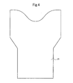
Fig. 4 is a plan view of a panel of the diffuser. -
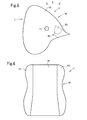
Fig. 5 is a side view of the passenger airbag according to the embodiment. -
Fig. 6 is a front view of the passenger airbag according to the embodiment. -
Fig. 7 is a perspective view of the passenger airbag during inflation as seen from the front of the vehicle. -
Fig. 8 is a vertical sectional view of the passenger airbag during inflation taken along the left-right direction. - An embodiment will be described below with reference to
Figs. 1 to 8 . - As illustrated in
Figs. 1 to 6 , thispassenger airbag 1 has an airbagmain body 10 and adiffuser 20 within the airbagmain body 10.Vent holes 11 are provided in both left and right side surfaces of the airbagmain body 10. Aninflator opening 12 is provided in the bottom surface of the airbagmain body 10 closer to the front end of the vehicle. T denotes a surface facing the passenger. - The airbag
main body 10 is made by sewing together acenter panel 14 as a main panel and left andright side panels Fig. 6 . Thecenter panel 14 forms the upper surface, the surface T facing the passenger, and the lower surface of the airbagmain body 10 in the inflated state. The left andright side panels main body 10. Avent hole 11 is provided in eachside panel 15. - The
diffuser 20 is made by sewing together afirst panel 21 on the rear side of the vehicle and asecond panel 22 on the front side withseams Figs. 1 and2 . Theseam 23 sews together the side edges of thepanels seam 24 sews together the upper edges of thepanels - The
panels Fig. 3 . Theseam 23 sews together the side edges of thepanels panels Gas discharge openings diffuser 20 as illustrated inFig. 2 . - As illustrated in
Fig. 3 , thepanels Fig. 2 , adepression 26 depressed toward the proximal end, that is, downward is formed in the center of the upper part of thediffuser 20 in the fully inflated state. - In the fully inflated state, the opening area of each gas discharge opening 25 is preferably about 1.1 to 3.0 times, especially about 1.3 to 2.0 times, the opening area of each
vent hole 11. The opening area of eachvent hole 11 is preferably about 12 to 51 cm2, especially about 19 to 40 cm2. - In the fully inflated state, the distance W between the left gas discharge opening 25 and the right gas discharge opening 25 is preferably about 230 to 440 mm, especially about 270 to 380 mm.
- In addition, in the fully inflated state, the difference in height H between the upper ends of both left and right ends of the
diffuser 20 and the lowest part of thedepression 26 is preferably about 50 to 160 mm, especially about 70 to 130 mm. - The
first panel 21 of thediffuser 20 is provided with an inflator opening 27 (Fig. 1 ) that is superimposed on theinflator opening 12 of the airbagmain body 10, and the peripheral edges of theopenings seam 28. - The
passenger airbag 1 is made by sewing together thecenter panel 14, theside panels 15, the first andsecond panels Fig. 1 ) of the airbagmain body 10 closer to the front end of the vehicle, and then sewing up the opening F with aseam 29. The first andsecond panels center panel 14 by theseam 29. Since the first andsecond panels center panel 14 in this manner, the man-hours for sewing theairbag 1 can be reduced, and theair bag 1 can be manufactured easily. - The passenger airbag device is installed in the upper surface of the
IP 32. The airbagmain body 10 and thediffuser 20 are fastened to aretainer 31 such that the peripheral edges of theinflator openings Fig. 8 ) 31r and the bottom surface of theretainer 31. - In case of front collision of a vehicle equipped with this passenger airbag device, the
inflator 30 is activated to generate gas, and the gas flows through thediffuser 20 into the airbagmain body 10. Thediffuser 20 inflates, a lid portion 33 (Fig. 7 ) of theIP 32 thereby starts to open, and thediffuser 20 and the airbagmain body 10 start to deploy above theIP 32. In this early stage of deployment, thediffuser 20 is quickly almost fully inflated, and thegas discharge openings 25 are located above theIP 32. When an interfering object M is close to the passenger airbag device of theIP 32 during the inflation of the airbag, the inflated airbagmain body 10 presses this interfering object M. However, since thediffuser 20 is disposed within the airbagmain body 10, and gas from the inflator 30 flows through thegas discharge openings 25 of thediffuser 20 to the left and right, the airbag main body inflates mainly in the left-right direction, and the inflation toward the interfering object M is suppressed. In addition, thediffuser 20 is provided with thedepression 26, and thedepression 26 faces the interfering object M. Therefore, the pressing force (input) applied from thediffuser 20 and the airbagmain body 10 to the interfering object M is reduced. - In addition, in this embodiment, as illustrated in
Figs. 7 and8 , the vent holes 11 are located on the extension lines of the gas outflow directions through thegas discharge openings 25 of thediffuser 20 when the airbagmain body 10 inflates in the left-right direction in the early stage of inflation. Therefore, gas flowing from thediffuser 20 into the airbagmain body 10 goes straight ahead and quickly flows through the vent holes 11 to the airbagmain body 10 side. Therefore, the inflation pressure of the airbagmain body 10 is low. Also by this, the input applied to the interfering object M is reduced. - When there is no interfering object M, the airbag
main body 10 quickly inflates from the state ofFigs. 7 and8 toward the rear of the vehicle, and the vent holes 11 move so as to be located behind thegas discharge openings 25. Therefore, thegas discharge openings 25 and the vent holes 11 come out of alignment with each other, the gas outflow through the vent holes 11 decreases, and the airbagmain body 10 quickly inflates to the fully inflated state. In the fully inflated state ofFig. 1 , the vent holes 11 are preferably separated from thegas discharge openings 25 toward the rear of the vehicle by 80 mm or more, which is the distance between the centers of the openings of the vent holes 11 and thegas discharge openings 25. - In the present invention, a tether for restricting the left-right width of the inflated airbag main body may be provided.
- Although the present invention has been described in detail by using a specific embodiment, it is obvious to those skilled in the art that various changes may be made without departing from the spirit and scope of the present invention.
- This application is based upon Japanese Patent Application No.
2011-199581 filed on September 13, 2011
Claims (10)
- A passenger airbag comprising:an airbag main body that is provided with vent holes in both side surfaces and that is provided with an inflator opening at a proximal end; anda diffuser that is disposed within the airbag main body and that has gas discharge openings for causing gas from an inflator to flow toward the sides of the airbag main body,wherein a central part in the left-right direction of the diffuser in the inflated state is located closer to the proximal end than a left end and a right end.
- The passenger airbag according to Claim 1, wherein in the passenger airbag, in the early stage of inflation, the vent holes are located in extension directions of gas outflow directions through the gas discharge openings of the diffuser, and in the fully inflated state of the passenger airbag, the vent holes are located closer to the rear of the vehicle than the gas discharge openings.
- The passenger airbag according to Claim 1 or 2,
wherein in the diffuser, in the fully inflated state, the distance between the left and right gas discharge openings is 230 to 440 mm, and
wherein the central part of the diffuser is located closer to the proximal end than the left end and right end by 50 to 160 mm. - The passenger airbag according to any one of Claims 1 to 3, wherein the opening area of the gas discharge openings of the diffuser in the fully inflated state is 1.1 to 3.0 times the opening area of the vent holes.
- The passenger airbag according to any one of Claims 1 to 4, wherein an edge of the diffuser closer to the front end of the vehicle is connected to an edge of the airbag main body closer to the front end of the vehicle.
- The passenger airbag according to Claim 5,
wherein the diffuser is formed by sewing together a first panel located closer to the rear of the vehicle when mounted in the vehicle and a second panel located closer to the front of the vehicle when mounted in the vehicle, and
wherein edges of the first panel and the second panel closer to the front end of the vehicle are sewn together with a main panel forming the airbag main body, on the side of the airbag main body closer to the front end of the vehicle. - The passenger airbag according to Claim 6,
wherein the first panel and the second panel each have, in their upper parts, a pair of protruding portions protruding in the left-right direction, and have such a substantially Y shape that the central part in the left-right direction of the upper edge is depressed,
wherein the upper edges of the first panel and the second panel are sewn together, and parts of the left and right side edges closer to the lower edges than the protruding portions, of the first panel and the second panel are sewn together,
wherein unsewn parts at the distal ends in the protruding direction of the protruding portions form the gas discharge openings,
wherein the main panel has a center panel that forms an upper surface, a surface facing a passenger, and a lower surface of the airbag main body in the inflated state, and a pair of side panels that form left and right surfaces of the airbag main body, and
wherein when manufacturing the airbag, the left and right surfaces of the center panel and the peripheral edges of the side panels are sewn together, the upper edges and side edges of the first panel and the second panel are sewn together, then the diffuser is disposed within the airbag main body through an opening closer to the front end of the vehicle between both unsewn ends of the center panel, and then both ends of the center panel and the lower edges of the first panel and the second panel are sewn together. - The passenger airbag according to Claim 6 or 7, wherein the first panel is provided with an inflator opening, and the peripheral edges of the gas discharge openings of the first panel and the airbag main body are sewn together.
- A passenger airbag device comprising: the passenger airbag according to any one of Claims 1 to 8; and an inflator for inflating the passenger airbag.
- A vehicle comprising: the passenger airbag device according to Claim 9.
Applications Claiming Priority (2)
| Application Number | Priority Date | Filing Date | Title |
|---|---|---|---|
| JP2011199581A JP5790354B2 (en) | 2011-09-13 | 2011-09-13 | Passenger seat airbag, passenger seat airbag apparatus and vehicle |
| PCT/JP2012/069559 WO2013038827A1 (en) | 2011-09-13 | 2012-08-01 | Passenger-side airbag, passenger-side airbag device, and vehicle |
Publications (3)
| Publication Number | Publication Date |
|---|---|
| EP2756999A1 true EP2756999A1 (en) | 2014-07-23 |
| EP2756999A4 EP2756999A4 (en) | 2015-09-16 |
| EP2756999B1 EP2756999B1 (en) | 2017-03-15 |
Family
ID=47883066
Family Applications (1)
| Application Number | Title | Priority Date | Filing Date |
|---|---|---|---|
| EP12832557.8A Not-in-force EP2756999B1 (en) | 2011-09-13 | 2012-08-01 | Passenger-side airbag, passenger-side airbag device, and vehicle |
Country Status (5)
| Country | Link |
|---|---|
| US (1) | US9539979B2 (en) |
| EP (1) | EP2756999B1 (en) |
| JP (1) | JP5790354B2 (en) |
| CN (1) | CN103796881B (en) |
| WO (1) | WO2013038827A1 (en) |
Families Citing this family (8)
| Publication number | Priority date | Publication date | Assignee | Title |
|---|---|---|---|---|
| KR101731808B1 (en) * | 2015-11-26 | 2017-05-02 | 현대모비스 주식회사 | An air bag apparatus |
| JP6658008B2 (en) * | 2016-01-29 | 2020-03-04 | Joyson Safety Systems Japan株式会社 | Airbag and airbag device |
| DE202016107171U1 (en) * | 2016-12-20 | 2018-03-21 | Dalphi Metal Espana, S.A. | Front airbag |
| US11066032B2 (en) * | 2019-12-06 | 2021-07-20 | Ford Global Technologies, Llc | Dash mounted airbag |
| KR102742149B1 (en) * | 2020-01-28 | 2024-12-13 | 현대모비스 주식회사 | Passenger air bag |
| JP7736495B2 (en) * | 2021-09-15 | 2025-09-09 | 株式会社Subaru | Vehicle airbag device |
| JP7786315B2 (en) * | 2022-08-01 | 2025-12-16 | トヨタ自動車株式会社 | Passenger-seat airbag device for a vehicle |
| JP7683563B2 (en) * | 2022-08-01 | 2025-05-27 | トヨタ自動車株式会社 | Passenger seat airbag device for vehicle |
Family Cites Families (31)
| Publication number | Priority date | Publication date | Assignee | Title |
|---|---|---|---|---|
| JPH03281460A (en) | 1990-03-29 | 1991-12-12 | Mazda Motor Corp | Air bag device for automobile |
| JPH0948307A (en) | 1995-08-11 | 1997-02-18 | Denso Corp | Airbag manufacturing method |
| JPH1071904A (en) | 1996-08-30 | 1998-03-17 | Denso Corp | Airbag device |
| JP3365258B2 (en) | 1997-06-16 | 2003-01-08 | 豊田合成株式会社 | Airbag device for passenger seat |
| US5927748A (en) * | 1997-06-26 | 1999-07-27 | O'driscoll; Peter | Multi-stage inflatable bag for vehicular safety systems |
| JP3399320B2 (en) | 1997-10-21 | 2003-04-21 | トヨタ自動車株式会社 | Airbag device for passenger seat |
| JPH11198750A (en) * | 1998-01-16 | 1999-07-27 | Takata Kk | Air bag device for front passenger's seat |
| JP3983419B2 (en) * | 1999-04-02 | 2007-09-26 | カルソニックカンセイ株式会社 | Airbag device for vehicle |
| US6439603B2 (en) * | 1999-10-13 | 2002-08-27 | Delphi Technologies, Inc. | Air bag module with variable inflation |
| CA2420745A1 (en) * | 2002-04-26 | 2003-10-26 | David E. Thomas | Front passenger airbag pocket baffle |
| US7195279B2 (en) * | 2003-09-04 | 2007-03-27 | Autoliv Asp, Inc. | Gas flow deflection apparatus and method for airbag systems |
| US7614653B2 (en) * | 2006-09-27 | 2009-11-10 | Autoliv Asp, Inc. | Pre-folded airbag cushion with optional venting for out-of-position conditions |
| US7722080B2 (en) * | 2006-09-27 | 2010-05-25 | Autoliv Asp, Inc. | Airbag cushion with a flap vent to optionally vent gas for out-of-position conditions |
| JP4297001B2 (en) | 2004-07-06 | 2009-07-15 | 豊田合成株式会社 | Airbag device |
| US7530597B2 (en) * | 2004-07-06 | 2009-05-12 | Toyoda Gosei Co., Ltd. | Airbag device for front passenger's seat |
| US7455317B2 (en) * | 2004-09-09 | 2008-11-25 | Toyoda Gosei Co., Ltd. | Airbag for front passenger's seat |
| JP4347281B2 (en) * | 2005-08-29 | 2009-10-21 | トヨタ自動車株式会社 | Passenger airbag |
| US7325830B2 (en) * | 2005-09-05 | 2008-02-05 | Honda Motor Co., Ltd. | Airbag device for vehicles |
| US7942440B2 (en) * | 2005-12-22 | 2011-05-17 | Autoliv Asp, Inc. | Channel and diffuser airbag |
| US7347445B2 (en) * | 2006-05-12 | 2008-03-25 | Hyundai Motor Company | Vehicle airbag device with an auxiliary chamber |
| US7748738B2 (en) * | 2006-09-27 | 2010-07-06 | Autoliv Asp, Inc. | Airbag cushion with adaptive diffuser for out-of-position conditions |
| US7731232B2 (en) * | 2006-12-18 | 2010-06-08 | Honda Motor Co., Ltd. | Vehicle airbag device |
| US7597356B2 (en) * | 2007-06-05 | 2009-10-06 | Autoliv Asp, Inc. | Airbag cushions with gas deflectors and optional venting for out-of-position conditions |
| US7883109B2 (en) * | 2007-12-20 | 2011-02-08 | Toyoda Gosei Co. Ltd. | Dynamic airbag venting |
| JP2010111331A (en) * | 2008-11-07 | 2010-05-20 | Toyoda Gosei Co Ltd | Airbag device for front passenger seat |
| JP2010120443A (en) * | 2008-11-18 | 2010-06-03 | Toyota Motor Corp | Front passenger airbag device |
| JP5233974B2 (en) * | 2009-12-02 | 2013-07-10 | トヨタ自動車株式会社 | Airbag device |
| JP5641637B2 (en) * | 2009-12-23 | 2014-12-17 | タカタ株式会社 | Air bag and air bag device |
| JP5195865B2 (en) * | 2010-10-18 | 2013-05-15 | トヨタ自動車株式会社 | Airbag device for passenger seat |
| JP5662814B2 (en) * | 2011-01-21 | 2015-02-04 | 芦森工業株式会社 | Airbag device |
| JP5712913B2 (en) * | 2011-12-15 | 2015-05-07 | タカタ株式会社 | Passenger seat airbag, passenger seat airbag apparatus and vehicle |
-
2011
- 2011-09-13 JP JP2011199581A patent/JP5790354B2/en not_active Expired - Fee Related
-
2012
- 2012-08-01 US US14/344,633 patent/US9539979B2/en not_active Expired - Fee Related
- 2012-08-01 EP EP12832557.8A patent/EP2756999B1/en not_active Not-in-force
- 2012-08-01 WO PCT/JP2012/069559 patent/WO2013038827A1/en not_active Ceased
- 2012-08-01 CN CN201280044317.4A patent/CN103796881B/en not_active Expired - Fee Related
Also Published As
| Publication number | Publication date |
|---|---|
| JP2013060100A (en) | 2013-04-04 |
| WO2013038827A1 (en) | 2013-03-21 |
| US20140353952A1 (en) | 2014-12-04 |
| JP5790354B2 (en) | 2015-10-07 |
| CN103796881B (en) | 2016-06-22 |
| CN103796881A (en) | 2014-05-14 |
| EP2756999B1 (en) | 2017-03-15 |
| EP2756999A4 (en) | 2015-09-16 |
| US9539979B2 (en) | 2017-01-10 |
Similar Documents
| Publication | Publication Date | Title |
|---|---|---|
| EP2756999B1 (en) | Passenger-side airbag, passenger-side airbag device, and vehicle | |
| CN104175997B (en) | Airbags and Airbag Devices | |
| JP4161705B2 (en) | Side airbag and side airbag device | |
| JP6156187B2 (en) | Crew protection device | |
| US7407185B2 (en) | Passenger airbag with a diffuser | |
| JP6446908B2 (en) | Passenger leg restraining device | |
| CN109693635B (en) | Airbag device | |
| US10525924B2 (en) | Occupant leg restraint device | |
| CN109229052B (en) | Airbag device | |
| CN101808860A (en) | Airbag, and airbag device | |
| CN105523003B (en) | Curtain airbag | |
| JP2019018791A (en) | Air bag and occupant restraint device | |
| JP2015120382A (en) | Occupant crash protection device | |
| US8608200B2 (en) | Passenger seat air bag, passenger seat air bag apparatus and vehicle | |
| CN105523001A (en) | curtain airbag | |
| JP2018070102A (en) | Airbag for rear seat | |
| JP5989494B2 (en) | Air bag and air bag device | |
| EP1256491A2 (en) | Head-protecting bag device for occupants in an automobile | |
| JP6291855B2 (en) | Pedestrian airbag device and automobile | |
| CN101384454B (en) | Airbag and airbag device | |
| JP6658008B2 (en) | Airbag and airbag device | |
| EP2733023A1 (en) | Side airbag for vehicle | |
| JP2018134998A (en) | Air bag and air bag device | |
| JP2014083899A (en) | Air bag device |
Legal Events
| Date | Code | Title | Description |
|---|---|---|---|
| PUAI | Public reference made under article 153(3) epc to a published international application that has entered the european phase |
Free format text: ORIGINAL CODE: 0009012 |
|
| 17P | Request for examination filed |
Effective date: 20140226 |
|
| AK | Designated contracting states |
Kind code of ref document: A1 Designated state(s): AL AT BE BG CH CY CZ DE DK EE ES FI FR GB GR HR HU IE IS IT LI LT LU LV MC MK MT NL NO PL PT RO RS SE SI SK SM TR |
|
| DAX | Request for extension of the european patent (deleted) | ||
| RA4 | Supplementary search report drawn up and despatched (corrected) |
Effective date: 20150819 |
|
| RIC1 | Information provided on ipc code assigned before grant |
Ipc: B60R 21/205 20110101ALI20150813BHEP Ipc: B60R 21/2346 20110101AFI20150813BHEP Ipc: B60R 21/235 20060101ALI20150813BHEP Ipc: B60R 21/239 20060101ALI20150813BHEP |
|
| GRAP | Despatch of communication of intention to grant a patent |
Free format text: ORIGINAL CODE: EPIDOSNIGR1 |
|
| INTG | Intention to grant announced |
Effective date: 20161017 |
|
| GRAS | Grant fee paid |
Free format text: ORIGINAL CODE: EPIDOSNIGR3 |
|
| GRAA | (expected) grant |
Free format text: ORIGINAL CODE: 0009210 |
|
| AK | Designated contracting states |
Kind code of ref document: B1 Designated state(s): AL AT BE BG CH CY CZ DE DK EE ES FI FR GB GR HR HU IE IS IT LI LT LU LV MC MK MT NL NO PL PT RO RS SE SI SK SM TR |
|
| REG | Reference to a national code |
Ref country code: CH Ref legal event code: EP Ref country code: GB Ref legal event code: FG4D |
|
| REG | Reference to a national code |
Ref country code: IE Ref legal event code: FG4D |
|
| REG | Reference to a national code |
Ref country code: AT Ref legal event code: REF Ref document number: 875179 Country of ref document: AT Kind code of ref document: T Effective date: 20170415 |
|
| REG | Reference to a national code |
Ref country code: DE Ref legal event code: R096 Ref document number: 602012029949 Country of ref document: DE |
|
| REG | Reference to a national code |
Ref country code: NL Ref legal event code: MP Effective date: 20170315 |
|
| REG | Reference to a national code |
Ref country code: LT Ref legal event code: MG4D |
|
| PG25 | Lapsed in a contracting state [announced via postgrant information from national office to epo] |
Ref country code: GR Free format text: LAPSE BECAUSE OF FAILURE TO SUBMIT A TRANSLATION OF THE DESCRIPTION OR TO PAY THE FEE WITHIN THE PRESCRIBED TIME-LIMIT Effective date: 20170616 Ref country code: LT Free format text: LAPSE BECAUSE OF FAILURE TO SUBMIT A TRANSLATION OF THE DESCRIPTION OR TO PAY THE FEE WITHIN THE PRESCRIBED TIME-LIMIT Effective date: 20170315 Ref country code: HR Free format text: LAPSE BECAUSE OF FAILURE TO SUBMIT A TRANSLATION OF THE DESCRIPTION OR TO PAY THE FEE WITHIN THE PRESCRIBED TIME-LIMIT Effective date: 20170315 Ref country code: NO Free format text: LAPSE BECAUSE OF FAILURE TO SUBMIT A TRANSLATION OF THE DESCRIPTION OR TO PAY THE FEE WITHIN THE PRESCRIBED TIME-LIMIT Effective date: 20170615 Ref country code: FI Free format text: LAPSE BECAUSE OF FAILURE TO SUBMIT A TRANSLATION OF THE DESCRIPTION OR TO PAY THE FEE WITHIN THE PRESCRIBED TIME-LIMIT Effective date: 20170315 |
|
| REG | Reference to a national code |
Ref country code: AT Ref legal event code: MK05 Ref document number: 875179 Country of ref document: AT Kind code of ref document: T Effective date: 20170315 |
|
| PG25 | Lapsed in a contracting state [announced via postgrant information from national office to epo] |
Ref country code: RS Free format text: LAPSE BECAUSE OF FAILURE TO SUBMIT A TRANSLATION OF THE DESCRIPTION OR TO PAY THE FEE WITHIN THE PRESCRIBED TIME-LIMIT Effective date: 20170315 Ref country code: BG Free format text: LAPSE BECAUSE OF FAILURE TO SUBMIT A TRANSLATION OF THE DESCRIPTION OR TO PAY THE FEE WITHIN THE PRESCRIBED TIME-LIMIT Effective date: 20170615 Ref country code: LV Free format text: LAPSE BECAUSE OF FAILURE TO SUBMIT A TRANSLATION OF THE DESCRIPTION OR TO PAY THE FEE WITHIN THE PRESCRIBED TIME-LIMIT Effective date: 20170315 Ref country code: SE Free format text: LAPSE BECAUSE OF FAILURE TO SUBMIT A TRANSLATION OF THE DESCRIPTION OR TO PAY THE FEE WITHIN THE PRESCRIBED TIME-LIMIT Effective date: 20170315 |
|
| PG25 | Lapsed in a contracting state [announced via postgrant information from national office to epo] |
Ref country code: NL Free format text: LAPSE BECAUSE OF FAILURE TO SUBMIT A TRANSLATION OF THE DESCRIPTION OR TO PAY THE FEE WITHIN THE PRESCRIBED TIME-LIMIT Effective date: 20170315 |
|
| PG25 | Lapsed in a contracting state [announced via postgrant information from national office to epo] |
Ref country code: IT Free format text: LAPSE BECAUSE OF FAILURE TO SUBMIT A TRANSLATION OF THE DESCRIPTION OR TO PAY THE FEE WITHIN THE PRESCRIBED TIME-LIMIT Effective date: 20170315 Ref country code: ES Free format text: LAPSE BECAUSE OF FAILURE TO SUBMIT A TRANSLATION OF THE DESCRIPTION OR TO PAY THE FEE WITHIN THE PRESCRIBED TIME-LIMIT Effective date: 20170315 Ref country code: AT Free format text: LAPSE BECAUSE OF FAILURE TO SUBMIT A TRANSLATION OF THE DESCRIPTION OR TO PAY THE FEE WITHIN THE PRESCRIBED TIME-LIMIT Effective date: 20170315 Ref country code: RO Free format text: LAPSE BECAUSE OF FAILURE TO SUBMIT A TRANSLATION OF THE DESCRIPTION OR TO PAY THE FEE WITHIN THE PRESCRIBED TIME-LIMIT Effective date: 20170315 Ref country code: SK Free format text: LAPSE BECAUSE OF FAILURE TO SUBMIT A TRANSLATION OF THE DESCRIPTION OR TO PAY THE FEE WITHIN THE PRESCRIBED TIME-LIMIT Effective date: 20170315 Ref country code: CZ Free format text: LAPSE BECAUSE OF FAILURE TO SUBMIT A TRANSLATION OF THE DESCRIPTION OR TO PAY THE FEE WITHIN THE PRESCRIBED TIME-LIMIT Effective date: 20170315 Ref country code: EE Free format text: LAPSE BECAUSE OF FAILURE TO SUBMIT A TRANSLATION OF THE DESCRIPTION OR TO PAY THE FEE WITHIN THE PRESCRIBED TIME-LIMIT Effective date: 20170315 |
|
| PG25 | Lapsed in a contracting state [announced via postgrant information from national office to epo] |
Ref country code: SM Free format text: LAPSE BECAUSE OF FAILURE TO SUBMIT A TRANSLATION OF THE DESCRIPTION OR TO PAY THE FEE WITHIN THE PRESCRIBED TIME-LIMIT Effective date: 20170315 Ref country code: IS Free format text: LAPSE BECAUSE OF FAILURE TO SUBMIT A TRANSLATION OF THE DESCRIPTION OR TO PAY THE FEE WITHIN THE PRESCRIBED TIME-LIMIT Effective date: 20170715 Ref country code: PT Free format text: LAPSE BECAUSE OF FAILURE TO SUBMIT A TRANSLATION OF THE DESCRIPTION OR TO PAY THE FEE WITHIN THE PRESCRIBED TIME-LIMIT Effective date: 20170717 Ref country code: PL Free format text: LAPSE BECAUSE OF FAILURE TO SUBMIT A TRANSLATION OF THE DESCRIPTION OR TO PAY THE FEE WITHIN THE PRESCRIBED TIME-LIMIT Effective date: 20170315 |
|
| REG | Reference to a national code |
Ref country code: DE Ref legal event code: R097 Ref document number: 602012029949 Country of ref document: DE |
|
| PLBE | No opposition filed within time limit |
Free format text: ORIGINAL CODE: 0009261 |
|
| STAA | Information on the status of an ep patent application or granted ep patent |
Free format text: STATUS: NO OPPOSITION FILED WITHIN TIME LIMIT |
|
| PG25 | Lapsed in a contracting state [announced via postgrant information from national office to epo] |
Ref country code: DK Free format text: LAPSE BECAUSE OF FAILURE TO SUBMIT A TRANSLATION OF THE DESCRIPTION OR TO PAY THE FEE WITHIN THE PRESCRIBED TIME-LIMIT Effective date: 20170315 |
|
| 26N | No opposition filed |
Effective date: 20171218 |
|
| PG25 | Lapsed in a contracting state [announced via postgrant information from national office to epo] |
Ref country code: SI Free format text: LAPSE BECAUSE OF FAILURE TO SUBMIT A TRANSLATION OF THE DESCRIPTION OR TO PAY THE FEE WITHIN THE PRESCRIBED TIME-LIMIT Effective date: 20170315 |
|
| REG | Reference to a national code |
Ref country code: CH Ref legal event code: PL |
|
| PG25 | Lapsed in a contracting state [announced via postgrant information from national office to epo] |
Ref country code: MC Free format text: LAPSE BECAUSE OF FAILURE TO SUBMIT A TRANSLATION OF THE DESCRIPTION OR TO PAY THE FEE WITHIN THE PRESCRIBED TIME-LIMIT Effective date: 20170315 |
|
| REG | Reference to a national code |
Ref country code: DE Ref legal event code: R082 Ref document number: 602012029949 Country of ref document: DE Representative=s name: VOSSIUS & PARTNER PATENTANWAELTE RECHTSANWAELT, DE Ref country code: DE Ref legal event code: R081 Ref document number: 602012029949 Country of ref document: DE Owner name: JOYSON SAFETY SYSTEMS JAPAN K.K., JP Free format text: FORMER OWNER: TAKATA CORPORATION, TOKYO, JP |
|
| GBPC | Gb: european patent ceased through non-payment of renewal fee |
Effective date: 20170801 |
|
| PG25 | Lapsed in a contracting state [announced via postgrant information from national office to epo] |
Ref country code: LI Free format text: LAPSE BECAUSE OF NON-PAYMENT OF DUE FEES Effective date: 20170831 Ref country code: CH Free format text: LAPSE BECAUSE OF NON-PAYMENT OF DUE FEES Effective date: 20170831 |
|
| REG | Reference to a national code |
Ref country code: FR Ref legal event code: ST Effective date: 20180430 |
|
| REG | Reference to a national code |
Ref country code: IE Ref legal event code: MM4A |
|
| REG | Reference to a national code |
Ref country code: BE Ref legal event code: MM Effective date: 20170831 |
|
| PG25 | Lapsed in a contracting state [announced via postgrant information from national office to epo] |
Ref country code: LU Free format text: LAPSE BECAUSE OF NON-PAYMENT OF DUE FEES Effective date: 20170801 |
|
| PG25 | Lapsed in a contracting state [announced via postgrant information from national office to epo] |
Ref country code: GB Free format text: LAPSE BECAUSE OF NON-PAYMENT OF DUE FEES Effective date: 20170801 Ref country code: IE Free format text: LAPSE BECAUSE OF NON-PAYMENT OF DUE FEES Effective date: 20170801 |
|
| PG25 | Lapsed in a contracting state [announced via postgrant information from national office to epo] |
Ref country code: BE Free format text: LAPSE BECAUSE OF NON-PAYMENT OF DUE FEES Effective date: 20170831 Ref country code: FR Free format text: LAPSE BECAUSE OF NON-PAYMENT OF DUE FEES Effective date: 20170831 |
|
| PG25 | Lapsed in a contracting state [announced via postgrant information from national office to epo] |
Ref country code: MT Free format text: LAPSE BECAUSE OF NON-PAYMENT OF DUE FEES Effective date: 20170801 |
|
| PG25 | Lapsed in a contracting state [announced via postgrant information from national office to epo] |
Ref country code: HU Free format text: LAPSE BECAUSE OF FAILURE TO SUBMIT A TRANSLATION OF THE DESCRIPTION OR TO PAY THE FEE WITHIN THE PRESCRIBED TIME-LIMIT; INVALID AB INITIO Effective date: 20120801 |
|
| PG25 | Lapsed in a contracting state [announced via postgrant information from national office to epo] |
Ref country code: CY Free format text: LAPSE BECAUSE OF NON-PAYMENT OF DUE FEES Effective date: 20170315 |
|
| PG25 | Lapsed in a contracting state [announced via postgrant information from national office to epo] |
Ref country code: MK Free format text: LAPSE BECAUSE OF FAILURE TO SUBMIT A TRANSLATION OF THE DESCRIPTION OR TO PAY THE FEE WITHIN THE PRESCRIBED TIME-LIMIT Effective date: 20170315 |
|
| PG25 | Lapsed in a contracting state [announced via postgrant information from national office to epo] |
Ref country code: TR Free format text: LAPSE BECAUSE OF FAILURE TO SUBMIT A TRANSLATION OF THE DESCRIPTION OR TO PAY THE FEE WITHIN THE PRESCRIBED TIME-LIMIT Effective date: 20170315 |
|
| PG25 | Lapsed in a contracting state [announced via postgrant information from national office to epo] |
Ref country code: AL Free format text: LAPSE BECAUSE OF FAILURE TO SUBMIT A TRANSLATION OF THE DESCRIPTION OR TO PAY THE FEE WITHIN THE PRESCRIBED TIME-LIMIT Effective date: 20170315 |
|
| PGFP | Annual fee paid to national office [announced via postgrant information from national office to epo] |
Ref country code: DE Payment date: 20210819 Year of fee payment: 10 |
|
| REG | Reference to a national code |
Ref country code: DE Ref legal event code: R119 Ref document number: 602012029949 Country of ref document: DE |
|
| PG25 | Lapsed in a contracting state [announced via postgrant information from national office to epo] |
Ref country code: DE Free format text: LAPSE BECAUSE OF NON-PAYMENT OF DUE FEES Effective date: 20230301 |