EP2756970A1 - Lenker zur Übertragung von Kräften und Lenkereinrichtung - Google Patents
Lenker zur Übertragung von Kräften und Lenkereinrichtung Download PDFInfo
- Publication number
- EP2756970A1 EP2756970A1 EP14150204.7A EP14150204A EP2756970A1 EP 2756970 A1 EP2756970 A1 EP 2756970A1 EP 14150204 A EP14150204 A EP 14150204A EP 2756970 A1 EP2756970 A1 EP 2756970A1
- Authority
- EP
- European Patent Office
- Prior art keywords
- handlebar
- link
- rod
- composite material
- fiber composite
- Prior art date
- Legal status (The legal status is an assumption and is not a legal conclusion. Google has not performed a legal analysis and makes no representation as to the accuracy of the status listed.)
- Granted
Links
- 230000005540 biological transmission Effects 0.000 title description 3
- 239000002131 composite material Substances 0.000 claims abstract description 18
- 239000000835 fiber Substances 0.000 claims abstract description 15
- 239000003365 glass fiber Substances 0.000 claims abstract description 6
- 239000000725 suspension Substances 0.000 claims description 8
- 239000007787 solid Substances 0.000 abstract description 4
- 238000005452 bending Methods 0.000 description 6
- 238000005457 optimization Methods 0.000 description 5
- 238000000034 method Methods 0.000 description 3
- 238000004519 manufacturing process Methods 0.000 description 2
- 230000008878 coupling Effects 0.000 description 1
- 238000010168 coupling process Methods 0.000 description 1
- 238000005859 coupling reaction Methods 0.000 description 1
- 230000007257 malfunction Effects 0.000 description 1
- 238000004088 simulation Methods 0.000 description 1
- 125000006850 spacer group Chemical group 0.000 description 1
Images

Classifications
-
- B—PERFORMING OPERATIONS; TRANSPORTING
- B60—VEHICLES IN GENERAL
- B60G—VEHICLE SUSPENSION ARRANGEMENTS
- B60G3/00—Resilient suspensions for a single wheel
- B60G3/18—Resilient suspensions for a single wheel with two or more pivoted arms, e.g. parallelogram
- B60G3/28—Resilient suspensions for a single wheel with two or more pivoted arms, e.g. parallelogram at least one of the arms itself being resilient, e.g. leaf spring
-
- B—PERFORMING OPERATIONS; TRANSPORTING
- B60—VEHICLES IN GENERAL
- B60G—VEHICLE SUSPENSION ARRANGEMENTS
- B60G11/00—Resilient suspensions characterised by arrangement, location or kind of springs
- B60G11/02—Resilient suspensions characterised by arrangement, location or kind of springs having leaf springs only
-
- B—PERFORMING OPERATIONS; TRANSPORTING
- B60—VEHICLES IN GENERAL
- B60G—VEHICLE SUSPENSION ARRANGEMENTS
- B60G7/00—Pivoted suspension arms; Accessories thereof
- B60G7/001—Suspension arms, e.g. constructional features
-
- F—MECHANICAL ENGINEERING; LIGHTING; HEATING; WEAPONS; BLASTING
- F16—ENGINEERING ELEMENTS AND UNITS; GENERAL MEASURES FOR PRODUCING AND MAINTAINING EFFECTIVE FUNCTIONING OF MACHINES OR INSTALLATIONS; THERMAL INSULATION IN GENERAL
- F16F—SPRINGS; SHOCK-ABSORBERS; MEANS FOR DAMPING VIBRATION
- F16F1/00—Springs
- F16F1/36—Springs made of rubber or other material having high internal friction, e.g. thermoplastic elastomers
- F16F1/366—Springs made of rubber or other material having high internal friction, e.g. thermoplastic elastomers made of fibre-reinforced plastics, i.e. characterised by their special construction from such materials
- F16F1/368—Leaf springs
-
- B—PERFORMING OPERATIONS; TRANSPORTING
- B60—VEHICLES IN GENERAL
- B60G—VEHICLE SUSPENSION ARRANGEMENTS
- B60G2204/00—Indexing codes related to suspensions per se or to auxiliary parts
- B60G2204/10—Mounting of suspension elements
- B60G2204/14—Mounting of suspension arms
-
- B—PERFORMING OPERATIONS; TRANSPORTING
- B60—VEHICLES IN GENERAL
- B60G—VEHICLE SUSPENSION ARRANGEMENTS
- B60G2206/00—Indexing codes related to the manufacturing of suspensions: constructional features, the materials used, procedures or tools
- B60G2206/01—Constructional features of suspension elements, e.g. arms, dampers, springs
- B60G2206/10—Constructional features of arms
- B60G2206/15—Constructional features of arms the arm being resilient
-
- B—PERFORMING OPERATIONS; TRANSPORTING
- B60—VEHICLES IN GENERAL
- B60G—VEHICLE SUSPENSION ARRANGEMENTS
- B60G2206/00—Indexing codes related to the manufacturing of suspensions: constructional features, the materials used, procedures or tools
- B60G2206/01—Constructional features of suspension elements, e.g. arms, dampers, springs
- B60G2206/40—Constructional features of dampers and/or springs
- B60G2206/42—Springs
- B60G2206/428—Leaf springs
-
- B—PERFORMING OPERATIONS; TRANSPORTING
- B60—VEHICLES IN GENERAL
- B60G—VEHICLE SUSPENSION ARRANGEMENTS
- B60G2206/00—Indexing codes related to the manufacturing of suspensions: constructional features, the materials used, procedures or tools
- B60G2206/01—Constructional features of suspension elements, e.g. arms, dampers, springs
- B60G2206/70—Materials used in suspensions
- B60G2206/71—Light weight materials
- B60G2206/7101—Fiber-reinforced plastics [FRP]
Definitions
- the invention relates to a link for transmitting forces with a handlebar made of a fiber composite material.
- Handlebars are usually used as an indirect connection between a wheel carrier and a vehicle body of a motor vehicle. Such links can be designed for example as a bar counter. Stemenker have arranged at opposite ends of the handlebar rod ball joints or comparable in their function rubber bearings.
- a wishbone has a pivot at one end of the handlebar and a ball joint at the opposite end of the handlebar.
- a wishbone can also be understood as a combination of two rod end, with each one ball joint of the two rod counter spatially coincident.
- the handlebar can be configured as a trapezoidal link.
- a trapezoidal link has pivots arranged at opposite ends of the link bar. In such Trapezlenker axes of rotation of the hinges can be arranged spatially mutually entangled.
- handlebars serve to transmit tensile and compressive forces, whereby an almost torque-free introduction of the tensile and compressive forces is made possible by the arranged at the ends of the handlebars joints.
- the arranged on conventional handlebars on the handlebars joints are usually exposed to high loads and frequent load changes.
- the stiffness of the rubber elements often used as a joint changes depending on the temperature, which also affects a steering stiffness.
- bending joints can be formed from the fiber composite material in use of a fiber composite material for the production of the handlebar in end portions of the handlebar bar.
- These flexures have a particularly high deformability.
- Such bending joints are known for example in the form of film joints, as used in injection-molded components. High tensile forces can be transmitted via these bending joints. However, only comparatively low compressive forces can be transmitted via the conventional bending joints as soon as a force introduction direction of the pressure force is not in the axial direction of the handlebar bar.
- the object of the invention is therefore considered to develop links with a handlebar made of fiber composite material so that comparatively high tensile and compressive forces can be transmitted by the handlebar, the handlebar is designed particularly wear.
- the handlebar at least forms a solid-state hinge and that the handlebar has only solid joints, which are formed by the handlebar.
- the rotation and pivotal movements performed by conventional links through the joints arranged in the opposite end portions of the link bar are performed by elastically deforming the entire link bar from the fiber composite.
- compressive and tensile forces as well as torsion moments can be transmitted particularly effectively over the handlebars.
- the use of, for example, particularly wear-prone rubber elements can be dispensed with as joints at the opposite ends of the handlebar.
- a high power transmission via the handlebar is inventively made possible in that the handlebar rod is elastically deformed along a disposed between opposite end portions of the handlebar rod, contiguous deformation region of the handlebar, when the handlebar is deflected.
- the entire deformation region acts as a solid-body joint
- the handlebar can be connected to the end regions of the handlebar rod rigidly, for example with the wheel carrier and the vehicle body.
- a geometry of the handle bar or The deformation range and the end regions can be adapted with the aid of suitable modeling and optimization methods with regard to predetermined load and deformation parameters adapted to the respective intended use of the link.
- contour-optimized link bars can be provided whose geometry is adapted to the loads occurring in the respective application, so that the entire contour-optimized link rod or the deformation area serves as a solid-body joint.
- a particularly good power transmission of the handlebar can be achieved in that the entire deformation range forms the solid-state joint.
- the handlebar rod forms two solid-state joints, each with three rotational degrees of freedom.
- a kinematics of a conventional rod end block, at the ends of each a ball joint is arranged to be emulated.
- the link according to the invention can be made particularly cost-effective and simple in that the handlebar is made in one piece.
- the handlebar consisting of the handlebar can be easily made of so-called prepregs from the fiber composite material.
- the handlebar is made of a glass fiber composite material.
- the Glass fiber composite material has a low modulus of elasticity and thereby allows comparatively large deformations of the handlebar or handlebar.
- Glass fiber composite material has a particularly high fatigue strength, so that with the help of the glass fiber composite material particularly durable handlebars or handlebars can be produced, which can transmit tensile and compressive forces almost without wear over a variety of load changes.
- the handlebar has a continuously changing in the axial direction cross-sectional surface profile.
- the geometry or a contour of the handle bar can be adapted particularly well to the respective load specifications by means of suitable optimization methods.
- the invention provides that a link geometry is adapted to predetermined load and deformation parameters. Appropriate modeling and optimization techniques can be used for this purpose.
- the handlebar has at least two spaced and parallel aligned handlebars, whose mutually associated ends are rigidly interconnected.
- Each individual handlebar can then have a comparatively small cross-sectional area and have a correspondingly low weight.
- the at least two link rods are additionally connected to each other in a central region spaced from the ends.
- handlebar has at least two rigidly interconnected and at an angle to each other aligned handlebars made of fiber composite material.
- the link is designed as a wishbone.
- two connecting rods each forming at least one solid-body joint, can be rigidly connected to one another in each case in one end region of the connecting rods, while opposite end regions are spaced apart from one another
- the required for the simulation of the function of a wishbone determination of the kinematic degrees of freedom of the handlebar or the adjustment of the handlebars to be absorbed by wishbones usually high side forces to each other by a suitable arrangement of the individual handlebars and a corresponding optimization of the handle bar geometries and an overall geometry of the handlebar.
- the invention also relates to a link device with a link according to one of the embodiments described above for transmitting forces between a body part and a suspension part.
- the body part is the vehicle body of a motor vehicle and the wheel suspension part may be, for example, the wheel carrier.
- the link device is characterized in that the link is rigidly connected to the body part and the suspension part.
- a link device can be provided in which can be dispensed with expensive and wear-prone joints for connecting a handlebar rod with the suspension member and the body part.
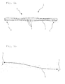
- Fig. 1a shows a schematic representation of a link 1 made of a fiber composite material, wherein the link 1 consists of a handlebar 2.
- the link rod 2 has a continuously changing cross-sectional surface course in the axial direction of the link rod 2. This cross-sectional surface profile has been determined with the aid of suitable modeling and optimization methods as a function of predetermined load and deformation parameters for a specific application of the illustrated link 1.
- a fiber direction of the fibers of the fiber composite material used for the production of the link is shown schematically by fiber lines 3.
- the link rod 2 of the link 1 has a deformation region 5 arranged between opposite end regions 4 of the link rod 2, wherein the entire deformation region 5 forms a solid-state joint.
- Fig. 1b schematically a deformation line 6 is shown, along which the in Fig. 1a shown handlebar 1 under a marked by the arrows 7 and acting on the handlebar bar 2 pressure load deformed.
- a handlebar 1 ' is shown, the three spaced and parallel aligned handlebars 2 has.
- the individual handlebars 2 each have a shape, or a cross-sectional surface course according to Fig. 1a on and are merely simplified represented by a line.
- the three link bars 2 are each rigidly connected to each other at the mutually associated end regions 4 in a receiving device 8, so that when a force is applied, all the link bars 2 undergo a substantially coinciding deformation.
- Fig. 2 exemplified an advantageous s-shaped deformation of the handlebars 2 is shown. By an appropriate distance between adjacent handlebars 2 can be avoided that adjacent handlebars touch 2 in a deformation and rub against each other.
- Each individual handlebar 2 of the handlebar 1 ' can be considerably thinner than in one in the Fig. 1a be illustrated handlebar 1 configured. Due to the parallel arrangement of the end portions 4 rigidly interconnected link rods 2 can still relatively high tensile and compressive forces on the handlebar 1 'are transmitted. Such a handlebar 1 'is suitable due to the shorter length of the individual handlebars 2 in comparison with the in Fig. 1a shown handlebar 1 especially in confined spaces.
- the adjacent link bars 2 are rigidly connected or spaced apart by a spacer 9, as it is schematically in Fig. 3 is shown.
- a spacer 9 In a central region act on each handlebar rod 2 only small or no bending moments, so that a torque-free fixing of the adjacent link bars 2 to each other is possible.
- a buckling of individual link bars 2 can be reduced or completely prevented by the predetermined distance to adjacent link bars 2 and the coupling of the link bars 2 caused thereby to a handlebar package.
Landscapes
- Engineering & Computer Science (AREA)
- Mechanical Engineering (AREA)
- General Engineering & Computer Science (AREA)
- Steering Devices For Bicycles And Motorcycles (AREA)
Abstract
Description
- Die Erfindung betrifft einen Lenker zur Übertragung von Kräften mit einem Lenkerstab aus einem Faserverbundwerkstoff.
- Lenker werden üblicherweise als mittelbare Verbindung zwischen einem Radträger und einem Fahrzeugkörper eines Kraftfahrzeugs eingesetzt. Solche Lenker können beispielsweise als Stablenker ausgeführt sein. Stablenker weisen an gegenüberliegenden Enden des Lenkerstabs angeordnete Kugelgelenke oder in ihrer Funktion vergleichbare Gummilager auf.
- Zur Verbindung des Radträgers - der Teil einer Radaufhängung des Kraftfahrzeugs ist und der ein Radlager aufnimmt, an dem ein Fahrzeugrad drehbar gelagert angeordnet ist - mit dem Fahrzeugkörper können beispielsweise aber auch Lenker in Form von Dreieckslenkern eingesetzt werden. Ein Dreieckslenker weist an einem Ende des Lenkerstabs ein Drehgelenk auf und an dem gegenüberliegenden Ende des Lenkerstabs ein Kugelgelenk. Kinematisch kann ein solcher Dreieckslenker auch als Kombination zweier Stablenker aufgefasst werden, wobei jeweils ein Kugelgelenk der beiden Stablenker räumlich zusammenfällt.
- Des Weiteren kann der Lenker als Trapezlenker ausgestaltet sein. Ein Trapezlenker weist an den gegenüberliegenden Enden des Lenkerstabs angeordnete Drehgelenke auf. Bei solchen Trapezlenkern können Drehachsen der Drehgelenke räumlich gegeneinander verschränkt angeordnet sein.
- Im Allgemeinen dienen solche Lenker der Übertragung von Zug- und Druckkräften, wobei durch die an den Enden des Lenkerstabs angeordneten Gelenke eine nahezu momentenfreie Einleitung der Zug- und Druckkräfte ermöglicht wird. Die bei herkömmlichen Lenkern an den Lenkerstäben angeordneten Gelenke sind üblicherweise hohen Belastungen und häufigen Lastwechseln ausgesetzt. Darüber hinaus ändert sich eine Steifigkeit der häufig als Gelenk eingesetzten Gummielemente in Abhängigkeit der Temperatur, wodurch auch eine Lenkersteifigkeit beeinflusst wird.
- Anstelle der herkömmlicherweise eingesetzten Gelenke können bei Verwendung eines Faserverbundwerkstoffs zur Herstellung des Lenkerstabs in Endbereichen des Lenkerstabs Biegegelenke aus dem Faserverbundwerkstoff ausgeformt sein. Diese Biegegelenke weisen eine besonders große Verformbarkeit auf. Solche Biegegelenke sind beispielsweise in Form von Filmgelenken bekannt, wie sie bei spritzgegossenen Bauteilen eingesetzt werden. Über diese Biegegelenke können hohe Zugkräfte übertragen werden. Allerdings können über die herkömmlichen Biegegelenke nur vergleichsweise geringe Druckkräfte übertragen werden, sobald eine Krafteinleitungsrichtung der Druckkraft nicht in axialer Richtung des Lenkerstabs ist.
- Als Aufgabe der Erfindung wird es daher angesehen, Lenker mit einem Lenkerstab aus Faserverbundwerkstoff so weiterzuentwickeln, dass durch den Lenker vergleichsweise hohe Zug- und Druckkräfte übertragen werden können, wobei der Lenker besonders verschleißarm ausgestaltet ist.
- Diese Aufgabe wird erfindungsgemäß dadurch gelöst, dass der Lenkerstab mindestens ein Festkörpergelenk bildet und dass der Lenker ausschließlich Festkörpergelenke aufweist, die von dem Lenkerstab gebildet sind. Auf diese Weise werden die bei herkömmlichen Lenkern durch die in den gegenüberliegenden Endbereichen des Lenkerstabs angeordneten Gelenke ausgeführten Dreh- und Schwenkbewegungen durch eine elastische Verformung des gesamten Lenkerstabs aus dem Faserverbundwerkstoff ausgeführt. Dadurch können Druck- und Zugkräfte sowie Torsionsmomente besonders wirkungsvoll über den Lenker übertragen werden. Zudem kann auf den Einsatz beispielsweise besonders verschleißanfälliger Gummielemente als Gelenke an den gegenüberliegenden Enden des Lenkerstabs verzichtet werden.
- Eine hohe Kraftübertragung über den Lenker wird erfindungsgemäß dadurch ermöglicht, dass der Lenkerstab längs eines zwischen gegenüberliegenden Endbereichen des Lenkerstabs angeordneten, zusammenhängenden Verformungsbereichs des Lenkerstabs elastisch verformt ist, wenn der Lenker ausgelenkt ist. Auf diese Weise wirkt der gesamte Verformungsbereich als Festkörpergelenk, während der Lenker mit den Endbereichen des Lenkerstabs starr beispielsweise mit dem Radträger und dem Fahrzeugkörper verbunden werden kann. Eine Geometrie des Lenkerstabs bzw. des Verformungsbereichs und der Endbereiche kann mit Hilfe geeigneter Modellbildungs- und Optimierungsverfahren hinsichtlich vorgegebener und an den jeweiligen Einsatzzweck des Lenkers angepasster Belastungs- und Verformungsparameter angepasst werden. Auf diese Weise können konturoptimierte Lenkerstäbe bereitgestellt werden, deren Geometrie an die bei der jeweiligen Anwendung auftretenden Belastungen angepasst ist, so dass der gesamte konturoptimierte Lenkerstab bzw. der Verformungsbereich als Festkörpergelenk dient.
- Eine besonders gute Kraftübertragung des Lenkers kann dadurch erreicht werden, dass der gesamte Verformungsbereich das Festkörpergelenk bildet.
- Bei einer vorteilhaften Ausgestaltung des erfindungsgemäßen Lenkers ist vorgesehen, dass der Lenkerstab zwei Festkörpergelenke mit jeweils drei rotatorischen Freiheitsgraden bildet. Auf diese Weise kann mit Hilfe des erfindungsgemäßen Lenkers eine Kinematik eines herkömmlichen Stablenkers, an dessen Enden jeweils ein Kugelgelenk angeordnet ist, nachgebildet werden.
- Der erfindungsgemäße Lenker kann besonders kostengünstig und einfach dadurch hergestellt werden, dass der Lenker einstückig hergestellt ist. Erfindungsgemäß kann der aus dem Lenkerstab bestehende Lenker einfach aus sogenannten Prepregs aus dem Faserverbundwerkstoff hergestellt werden.
- Bei einer besonders vorteilhaften Ausgestaltung des erfindungsgemäßen Lenkers ist vorgesehen, dass der Lenker aus einem Glasfaserverbundwerkstoff hergestellt ist. Der Glasfaserverbundwerkstoff weist einen niedrigen Elastizitätsmodul auf und ermöglicht dadurch vergleichsweise große Verformungen des Lenkers bzw. Lenkerstabs. Des Weiteren weist der
- Glasfaserverbundwerkstoff eine besonders hohe Ermüdungsfestigkeit auf, so dass mit Hilfe des Glasfaserverbundwerkstoffs besonders haltbare Lenker bzw. Lenkerstäbe hergestellt werden können, die über eine Vielzahl von Lastwechseln nahezu verschleißfrei Zug- und Druckkräfte übertragen können.
- Bei einer vorteilhaften Ausgestaltung des erfindungsgemäßen Lenkers ist vorgesehen, dass der Lenkerstab einen sich in axialer Richtung kontinuierlich verändernden Querschnittsflächenverlauf aufweist. Auf diese Weise kann die Geometrie beziehungsweise eine Kontur des Lenkerstabs besonders gut an die jeweiligen Belastungsvorgaben mit Hilfe geeigneter Optimierungsverfahren angepasst werden.
- Vorteilhafterweise ist erfindungsgemäß vorgesehen, dass eine Lenkergeometrie an vorgegebene Belastungs- und Verformungsparameter angepasst ist. Zu diesem Zweck können geeignete Modellierungs- und Optimierungsverfahren eingesetzt werden.
- Um trotz einer möglichst geringen Ausdehnung des Lenkers in Richtung des Lenkerstabs eine möglichst hohe Deformation zu ermöglichen ist vorgesehen, dass der Lenker mindestens zwei beabstandet und parallel zueinander ausgerichtete Lenkerstäbe aufweist, deren einander zugeordnete Enden starr miteinander verbunden sind. Jeder einzelne Lenkerstab kann dann eine vergleichsweise kleine Querschnittsfläche und ein entsprechend geringes Eigengewicht aufweisen. Durch die Verwendung von zwei oder mehreren in einer vorgesehenen Deformationsrichtung nebeneinander, bzw. parallel zueinander angeordneten Lenkerstäbe, die mit geringem Kraftaufwand in Deformationsrichtung deformiert werden können, können gleichzeitig verhältnismäßig große Zug- und Druckkräfte übertragen werden.
- Bei mehreren dünnen Lenkerstäben besteht die Gefahr, dass die Lenkerstäbe bei einer übermäßig großen Krafteinwirkung von Druck- oder Torsionskräften knicken, wodurch sich die von dem Lenkerstab erzeugten Rückstellkräfte unkontrollierbar verändern und eine Fehlfunktion oder Beschädigung des Lenkers nicht mehr ausgeschlossen werden kann. Um ein Knicken der Lenkerstäbe zu verhindern, ist vorgesehen, dass die mindestens zwei Lenkerstäbe zusätzlich in einem mittleren Bereich beabstandet von den Enden miteinander verbunden sind.
- Die Funktionen herkömmlicher Dreiecks- und Trapezlenker können durch den erfindungsgemäßen Lenker einfach dadurch nachgebildet werden, dass der Lenker mindestens zwei starr miteinander verbundene und in einem Winkel zueinander ausgerichtete Lenkerstäbe aus dem Faserverbundwerkstoff aufweist.
- Vorteilhafterweise ist vorgesehen, dass der Lenker als Dreieckslenker ausgestaltet ist. Zu diesem Zweck können erfindungsgemäß zwei Lenkerstäbe, die jeweils mindestens ein Festkörpergelenk bilden, in jeweils einem Endbereich der Lenkerstäbe starr miteinander verbunden sein, während gegenüberliegende Endbereiche beabstandet zueinander beispielsweise mit dem Radträger einer Radaufhängung eines Kraftfahrzeugs verbunden sind. Die für die Nachbildung der Funktion eines Dreieckslenkers erforderliche Festlegung der kinematischen Freiheitsgrade des Lenkers beziehungsweise die Anpassung des Lenkers an die durch Dreieckslenker üblicherweise aufzunehmenden hohen Seitenkräfte erfolgt durch eine geeignete Anordnung der einzelnen Lenkerstäbe zueinander und eine entsprechende Optimierung der Lenkerstabgeometrien und einer Gesamtgeometrie des Lenkers.
- Die Erfindung betrifft auch eine Lenkereinrichtung mit einem Lenker gemäß einer der voranstehend beschriebenen Ausführungsformen zur Übertragung von Kräften zwischen einem Karosserieteil und einem Radaufhängungsteil. Bei dem Karosserieteil handelt es sich um den Fahrzeugkörper eines Kraftfahrzeugs und bei dem Radaufhängungsteil kann es sich beispielsweise um den Radträger handeln.
- Erfindungsgemäß ist die Lenkereinrichtung dadurch gekennzeichnet, dass der Lenker starr mit dem Karosserieteil und dem Radaufhängungsteil verbunden ist. Auf diese Weise kann eine Lenkereinrichtung bereitgestellt werden, bei der auf teure und verschleißanfällige Gelenke zur Verbindung eines Lenkerstabs mit dem Radaufhängungsteil und dem Karosserieteil verzichtet werden kann.
- Verschiedene vorteilhafte Ausgestaltungen von erfindungsgemäßen Lenkern werden anhand von in der Zeichnung dargestellten Ausführungsbeispielen näher erläutert.
- Es zeigt:
-
Fig. 1a eine schematisch dargestellte Schnittansicht eines Lenkers mit einem einzigen Lenkerstab, -
Fig. 1b eine schematisch dargestellte Verformungslinie längs derer sich der inFig. 1a dargestellte Lenker unter Druckbelastung und Biegung verformt, -
Fig. 2 eine schematische Schnittansicht eines Lenkers mit mehreren beabstandet zueinander angeordneten Lenkerstäben, die an deren jeweiligen Enden starr miteinander verbunden sind, und -
Fig. 3 eine schematische Schnittansicht eines Lenkers gemäßFig. 2 , wobei jeweils benachbarte Lenkerstäbe in einem mittleren Bereich miteinander verbunden sind. -
Fig. 1a zeigt eine schematische Darstellung eines Lenkers 1 aus einem Faserverbundwerkstoff, wobei der Lenker 1 aus einem Lenkerstab 2 besteht. Der Lenkerstab 2 weist einen sich in axialer Richtung des Lenkerstabs 2 kontinuierlich verändernden Querschnittsflächenverlauf auf. Dieser Querschnittsflächenverlauf ist mit Hilfe geeigneter Modellierungs- und Optimierungsverfahren in Anhängigkeit vorgegebener Belastungs- und Verformungsparameter für einen konkreten Anwendungsfall des dargestellten Lenkers 1 ermittelt worden. Eine Faserverlaufsrichtung der Fasern des zur Herstellung des Lenkers verwendeten Faserverbundwerkstoffs ist durch Faserverlaufslinien 3 schematisch dargestellt. - Der Lenkerstab 2 des Lenkers 1 weist einen zwischen gegenüberliegenden Endbereichen 4 des Lenkerstabs 2 angeordneten Verformungsbereich 5 auf, wobei der gesamte Verformungsbereich 5 ein Festkörpergelenk bildet.
- In
Fig. 1b ist schematisch eine Verformungslinie 6 dargestellt, entlang derer sich der inFig. 1a abgebildete Lenker 1 unter einer durch die Pfeile 7 gekennzeichneten und auf den Lenkerstab 2 wirkenden Druckbelastung verformt. - In
Fig. 2 ist schematisch ein Lenker 1' dargestellt, der drei beabstandet und parallel zueinander ausgerichtete Lenkerstäbe 2 aufweist. Die einzelnen Lenkerstäbe 2 weisen jeweils eine Formgebung, bzw. einen Querschnittsflächenverlauf gemäßFig. 1a auf und sind lediglich vereinfachend durch eine Linie dargestellt. Die drei Lenkerstäbe 2 sind an den einander zugeordneten Endbereichen 4 jeweils starr in einer Aufnahmeeinrichtung 8 miteinander verbunden, so dass bei einer Krafteinwirkung alle Lenkerstäbe 2 eine im Wesentlichen übereinstimmende Deformation erleiden. InFig. 2 ist exemplarisch eine vorteilhafte s-förmige Deformation der Lenkerstäbe 2 dargestellt. Durch einen angemessenen Abstand zwischen benachbarten Lenkerstäben 2 kann vermieden werden, dass sich benachbarte Lenkerstäbe 2 bei einer Deformation berühren und aneinander reiben. Jeder einzelne Lenkerstab 2 des Lenkers 1' kann erheblich dünner als bei einem in derFig. 1a dargestellten Lenker 1 ausgestaltet sein. Durch die parallele Anordnung der an den Endbereichen 4 starr miteinander verbundenen Lenkerstäbe 2 können trotzdem vergleichsweise hohe Zug- und Druckkräfte über den Lenker 1' übertragen werden. Ein derartiger Lenker 1' eignet sich auf Grund der geringeren Länge der einzelnen Lenkerstäbe 2 im Vergleich mit dem inFig. 1a dargestellten Lenker 1 besonders bei beengten Raumverhältnissen. - Um bei großen Zug- und Druckkräften ein unkontrollierbares Knicken der einzelnen Lenkerstäbe 2 bei dem Lenker 1' vermeiden zu können ist vorgesehen, dass etwa mittig zwischen den Endbereichen 4 die benachbarten Lenkerstäbe 2 starr bzw. abstandswahrend über einen Abstandshalter 9 miteinander verbunden sind, wie es schematisch in
Fig. 3 dargestellt ist. In einem mittleren Bereich wirken auf jeden einzelnen Lenkerstab 2 lediglich geringe bzw. keine Biegemomente, so dass eine momentenfreie Festlegung der benachbarten Lenkerstäbe 2 zueinander möglich ist. Ein Knicken einzelner Lenkerstäbe 2 kann durch den vorgegebenen Abstand zu benachbarten Lenkerstäben 2 und die dadurch bewirkte Kopplung der Lenkerstäbe 2 zu einem Lenkerstabpaket reduziert oder vollständig verhindert werden.
Claims (14)
- Lenker (1, 1') zur Übertragung von Kräften mit einem Lenkerstab (2) aus einem Faserverbundwerkstoff, dadurch gekennzeichnet, dass der Lenkerstab (2) mindestens ein Festkörpergelenk bildet und dass der Lenker (1) ausschließlich Festkörpergelenke aufweist, die von dem Lenkerstab gebildet sind.
- Lenker (1, 1') gemäß Anspruch 1, dadurch gekennzeichnet, dass der Lenkerstab (2) längs eines zwischen gegenüberliegenden Endbereichen (4) des Lenkerstabs (2) angeordneten, zusammenhängenden Verformungsbereichs (5) des Lenkerstabs (2) elastisch verformt ist, wenn der Lenker ausgelenkt ist.
- Lenker (1, 1') gemäß Anspruch 2, dadurch gekennzeichnet, dass der gesamte Verformungsbereich (5) das Festkörpergelenk bildet.
- Lenker (1, 1') gemäß einem der voranstehenden Ansprüche, dadurch gekennzeichnet, dass der Lenkerstab (2) zwei Festkörpergelenke mit jeweils drei rotatorischen Freiheitsgraden bildet.
- Lenker (1, 1') gemäß einem der voranstehenden Ansprüche, dadurch gekennzeichnet, dass der Lenker (1) einstückig hergestellt ist.
- Lenker (1, 1') gemäß einem der voranstehenden Ansprüche, dadurch gekennzeichnet, dass der Lenker (1) aus einem Glasfaserverbundwerkstoff hergestellt ist.
- Lenker (1, 1') gemäß einem der voranstehenden Ansprüche, dadurch gekennzeichnet, dass der Lenkerstab (2) einen sich in axialer Richtung kontinuierlich verändernden Querschnittflächenverlauf ausweist.
- Lenker (1, 1') gemäß einem der voranstehenden Ansprüche, dadurch gekennzeichnet, dass sich der Lenkerstab (2) bei einer Druckbelastung s-förmig verformt.
- Lenker (1, 1') gemäß einem der voranstehenden Ansprüche, dadurch gekennzeichnet, dass eine Lenkergeometrie an vorgegebene Belastungs- und Verformungsparameter angepasst ist.
- Lenker (1') gemäß einem der voranstehenden Ansprüche, dadurch gekennzeichnet, dass der Lenker mindestens zwei beabstandet und parallel zueinander ausgerichtete Lenkerstäbe aufweist, deren einander zugeordnete Enden starr miteinander verbunden sind.
- Lenker (1') gemäß Anspruch 10, dadurch gekennzeichnet, dass die mindestens zwei Lenkerstäbe zusätzlich in einem mittleren Bereich beabstandet von den Enden miteinander verbunden sind.
- Lenker gemäß einem der voranstehenden Ansprüche, dadurch gekennzeichnet, dass der Lenker mindestens zwei starr miteinander verbundene und in einem Winkel zueinander ausgerichtete Lenkerstäbe (2) aus dem Faserverbundwerkstoff aufweist.
- Lenker gemäß Anspruch 12, dadurch gekennzeichnet, dass der Lenker (1) als Dreieckslenker oder als Trapezlenker ausgestaltet ist.
- Lenkereinrichtung mit einem Lenker (1, 1') gemäß einem der voranstehenden Ansprüche zur Übertragung von Kräften zwischen einem Karosserieteil und einem Radaufhängungsteil, dadurch gekennzeichnet, dass der Lenker (1, 1') starr mit dem Karosserieteil und dem Radaufhängungsteil verbunden ist.
Applications Claiming Priority (1)
| Application Number | Priority Date | Filing Date | Title |
|---|---|---|---|
| DE201310100486 DE102013100486A1 (de) | 2013-01-17 | 2013-01-17 | Lenker zur Übertragung von Kräften und Lenkereinrichtung |
Publications (2)
| Publication Number | Publication Date |
|---|---|
| EP2756970A1 true EP2756970A1 (de) | 2014-07-23 |
| EP2756970B1 EP2756970B1 (de) | 2019-03-27 |
Family
ID=49885149
Family Applications (1)
| Application Number | Title | Priority Date | Filing Date |
|---|---|---|---|
| EP14150204.7A Active EP2756970B1 (de) | 2013-01-17 | 2014-01-06 | Lenker zur übertragung von kräften und lenkereinrichtung |
Country Status (2)
| Country | Link |
|---|---|
| EP (1) | EP2756970B1 (de) |
| DE (1) | DE102013100486A1 (de) |
Families Citing this family (1)
| Publication number | Priority date | Publication date | Assignee | Title |
|---|---|---|---|---|
| EP3452310B1 (de) * | 2016-05-03 | 2020-07-22 | Bayerische Motoren Werke Aktiengesellschaft | Einzelradaufhängung eines fahrzeugs mit einem radführenden blattfederelement aus einem faserverbund-werkstoff |
Citations (9)
| Publication number | Priority date | Publication date | Assignee | Title |
|---|---|---|---|---|
| FR2484926A1 (fr) * | 1980-06-19 | 1981-12-24 | Brondel Christian | Suspension de vehicule automobile |
| EP0213367A2 (de) * | 1985-08-24 | 1987-03-11 | Adam Opel Aktiengesellschaft | Radaufhängung für Fahrzeuge |
| EP0265682A1 (de) * | 1986-10-07 | 1988-05-04 | Pirelli Sistemi Antivibranti S.P.A. | Vorrichtung für Aufhängungen von Kraftfahrzeugen |
| GB2202498A (en) * | 1987-03-23 | 1988-09-28 | Benjamin V Booher | Spring beam vehicle suspension with inverted dihedral angle |
| EP0916525A2 (de) * | 1997-11-13 | 1999-05-19 | DaimlerChrysler AG | Führung für ein Kraftfahrzeugrad |
| EP1120298A1 (de) * | 2000-01-28 | 2001-08-01 | Peugeot Citroen Automobiles SA | Vorderradaufhängung mit transversaler Blattfeder |
| EP0760750B1 (de) * | 1995-03-06 | 2001-10-10 | Esoro Ag | Radaufhängung mit querblattfederung |
| EP1400380A2 (de) * | 2002-09-18 | 2004-03-24 | PD&E Automotive B.V. | Fahrzeugradaufhängung mit Querblattfeder |
| DE102008043330A1 (de) * | 2008-10-30 | 2010-05-12 | Zf Friedrichshafen Ag | Radaufhängung für ein Fahrzeug |
-
2013
- 2013-01-17 DE DE201310100486 patent/DE102013100486A1/de not_active Withdrawn
-
2014
- 2014-01-06 EP EP14150204.7A patent/EP2756970B1/de active Active
Patent Citations (9)
| Publication number | Priority date | Publication date | Assignee | Title |
|---|---|---|---|---|
| FR2484926A1 (fr) * | 1980-06-19 | 1981-12-24 | Brondel Christian | Suspension de vehicule automobile |
| EP0213367A2 (de) * | 1985-08-24 | 1987-03-11 | Adam Opel Aktiengesellschaft | Radaufhängung für Fahrzeuge |
| EP0265682A1 (de) * | 1986-10-07 | 1988-05-04 | Pirelli Sistemi Antivibranti S.P.A. | Vorrichtung für Aufhängungen von Kraftfahrzeugen |
| GB2202498A (en) * | 1987-03-23 | 1988-09-28 | Benjamin V Booher | Spring beam vehicle suspension with inverted dihedral angle |
| EP0760750B1 (de) * | 1995-03-06 | 2001-10-10 | Esoro Ag | Radaufhängung mit querblattfederung |
| EP0916525A2 (de) * | 1997-11-13 | 1999-05-19 | DaimlerChrysler AG | Führung für ein Kraftfahrzeugrad |
| EP1120298A1 (de) * | 2000-01-28 | 2001-08-01 | Peugeot Citroen Automobiles SA | Vorderradaufhängung mit transversaler Blattfeder |
| EP1400380A2 (de) * | 2002-09-18 | 2004-03-24 | PD&E Automotive B.V. | Fahrzeugradaufhängung mit Querblattfeder |
| DE102008043330A1 (de) * | 2008-10-30 | 2010-05-12 | Zf Friedrichshafen Ag | Radaufhängung für ein Fahrzeug |
Also Published As
| Publication number | Publication date |
|---|---|
| EP2756970B1 (de) | 2019-03-27 |
| DE102013100486A1 (de) | 2014-07-17 |
Similar Documents
| Publication | Publication Date | Title |
|---|---|---|
| EP3017211B1 (de) | Blattfeder und blattfederanordnung | |
| DE60002808T2 (de) | Propellerrotornabe | |
| DE10055961B4 (de) | Variabler Flügelbereich mit einstellbarer, sich in Spannweiten-Richtung erstreckender Profilform | |
| EP2751444B1 (de) | Halterung für eine feder | |
| DE102007049864B4 (de) | Sitzgestell eines Kraftfahrzeugsitzes mit einem Sitzträger, der zwei Seitenteile hat | |
| EP2885554B1 (de) | Blattfederanordnung für kraftfahrzeuge | |
| EP1636086B1 (de) | Flügel, insbesondere tragflügel eines flugzeugs, mit veränderbarem profil | |
| EP2233327B1 (de) | Mittelbügelsystem für ein Gelenkfahrzeug | |
| DE19636506A1 (de) | Schaltvorrichtung für ein Gangwechselgetriebe eines Kraftfahrzeuges | |
| DE3241754C2 (de) | Rotor, insbesondere eines Drehflügelflugzeuges | |
| DE202017007532U1 (de) | Scharnier zwischen einem Brillenrahmen und einem Brillenbügel | |
| EP2397279A1 (de) | Knickarmroboter mit Armantrieb | |
| DE112014004054T5 (de) | Drehmomentstab und Herstellungsverfahren davon | |
| DE10026119A1 (de) | Elastische Anordnung | |
| DE102013106385B4 (de) | Scharniervorrichtung | |
| EP3846984B1 (de) | Greiffinger mit gekrümmten abstandselementen sowie adaptive greifvorrichtung | |
| DE2910729C2 (de) | Multidirektionale Aufhängung für Hubschrauber-Antriebe | |
| EP2756970B1 (de) | Lenker zur übertragung von kräften und lenkereinrichtung | |
| DE102006011512A1 (de) | Vorrichtung zum Verstellen eines beweglichen Karosserieteils | |
| EP3113962B1 (de) | Feder-lenker-einrichtung | |
| DE102020130645A1 (de) | Parallelroboter | |
| EP2516254A1 (de) | Belastungsadaptiv ausgebildete bauteile | |
| DE102008022154B4 (de) | Vorrichtung zur aktiven Spurlenkung von Fahrzeugrädern | |
| EP2525928B2 (de) | Strangführungselement zum führen und stützen eines metallischen strangs in einer stranggiessmaschine | |
| DE102009009683A1 (de) | Drehmomentübertragungseinrichtung insbesondere für Automobile und Motorräder |
Legal Events
| Date | Code | Title | Description |
|---|---|---|---|
| PUAI | Public reference made under article 153(3) epc to a published international application that has entered the european phase |
Free format text: ORIGINAL CODE: 0009012 |
|
| 17P | Request for examination filed |
Effective date: 20140106 |
|
| AK | Designated contracting states |
Kind code of ref document: A1 Designated state(s): AL AT BE BG CH CY CZ DE DK EE ES FI FR GB GR HR HU IE IS IT LI LT LU LV MC MK MT NL NO PL PT RO RS SE SI SK SM TR |
|
| AX | Request for extension of the european patent |
Extension state: BA ME |
|
| R17P | Request for examination filed (corrected) |
Effective date: 20150123 |
|
| RBV | Designated contracting states (corrected) |
Designated state(s): AL AT BE BG CH CY CZ DE DK EE ES FI FR GB GR HR HU IE IS IT LI LT LU LV MC MK MT NL NO PL PT RO RS SE SI SK SM TR |
|
| 17Q | First examination report despatched |
Effective date: 20150416 |
|
| STAA | Information on the status of an ep patent application or granted ep patent |
Free format text: STATUS: EXAMINATION IS IN PROGRESS |
|
| GRAP | Despatch of communication of intention to grant a patent |
Free format text: ORIGINAL CODE: EPIDOSNIGR1 |
|
| STAA | Information on the status of an ep patent application or granted ep patent |
Free format text: STATUS: GRANT OF PATENT IS INTENDED |
|
| INTG | Intention to grant announced |
Effective date: 20181029 |
|
| GRAS | Grant fee paid |
Free format text: ORIGINAL CODE: EPIDOSNIGR3 |
|
| GRAA | (expected) grant |
Free format text: ORIGINAL CODE: 0009210 |
|
| STAA | Information on the status of an ep patent application or granted ep patent |
Free format text: STATUS: THE PATENT HAS BEEN GRANTED |
|
| AK | Designated contracting states |
Kind code of ref document: B1 Designated state(s): AL AT BE BG CH CY CZ DE DK EE ES FI FR GB GR HR HU IE IS IT LI LT LU LV MC MK MT NL NO PL PT RO RS SE SI SK SM TR |
|
| REG | Reference to a national code |
Ref country code: GB Ref legal event code: FG4D Free format text: NOT ENGLISH |
|
| REG | Reference to a national code |
Ref country code: CH Ref legal event code: EP |
|
| REG | Reference to a national code |
Ref country code: AT Ref legal event code: REF Ref document number: 1112614 Country of ref document: AT Kind code of ref document: T Effective date: 20190415 |
|
| REG | Reference to a national code |
Ref country code: IE Ref legal event code: FG4D Free format text: LANGUAGE OF EP DOCUMENT: GERMAN |
|
| REG | Reference to a national code |
Ref country code: DE Ref legal event code: R096 Ref document number: 502014011212 Country of ref document: DE |
|
| PG25 | Lapsed in a contracting state [announced via postgrant information from national office to epo] |
Ref country code: LT Free format text: LAPSE BECAUSE OF FAILURE TO SUBMIT A TRANSLATION OF THE DESCRIPTION OR TO PAY THE FEE WITHIN THE PRESCRIBED TIME-LIMIT Effective date: 20190327 Ref country code: SE Free format text: LAPSE BECAUSE OF FAILURE TO SUBMIT A TRANSLATION OF THE DESCRIPTION OR TO PAY THE FEE WITHIN THE PRESCRIBED TIME-LIMIT Effective date: 20190327 Ref country code: NO Free format text: LAPSE BECAUSE OF FAILURE TO SUBMIT A TRANSLATION OF THE DESCRIPTION OR TO PAY THE FEE WITHIN THE PRESCRIBED TIME-LIMIT Effective date: 20190627 Ref country code: FI Free format text: LAPSE BECAUSE OF FAILURE TO SUBMIT A TRANSLATION OF THE DESCRIPTION OR TO PAY THE FEE WITHIN THE PRESCRIBED TIME-LIMIT Effective date: 20190327 |
|
| REG | Reference to a national code |
Ref country code: NL Ref legal event code: MP Effective date: 20190327 |
|
| PG25 | Lapsed in a contracting state [announced via postgrant information from national office to epo] |
Ref country code: HR Free format text: LAPSE BECAUSE OF FAILURE TO SUBMIT A TRANSLATION OF THE DESCRIPTION OR TO PAY THE FEE WITHIN THE PRESCRIBED TIME-LIMIT Effective date: 20190327 Ref country code: GR Free format text: LAPSE BECAUSE OF FAILURE TO SUBMIT A TRANSLATION OF THE DESCRIPTION OR TO PAY THE FEE WITHIN THE PRESCRIBED TIME-LIMIT Effective date: 20190628 Ref country code: LV Free format text: LAPSE BECAUSE OF FAILURE TO SUBMIT A TRANSLATION OF THE DESCRIPTION OR TO PAY THE FEE WITHIN THE PRESCRIBED TIME-LIMIT Effective date: 20190327 Ref country code: BG Free format text: LAPSE BECAUSE OF FAILURE TO SUBMIT A TRANSLATION OF THE DESCRIPTION OR TO PAY THE FEE WITHIN THE PRESCRIBED TIME-LIMIT Effective date: 20190627 Ref country code: RS Free format text: LAPSE BECAUSE OF FAILURE TO SUBMIT A TRANSLATION OF THE DESCRIPTION OR TO PAY THE FEE WITHIN THE PRESCRIBED TIME-LIMIT Effective date: 20190327 Ref country code: NL Free format text: LAPSE BECAUSE OF FAILURE TO SUBMIT A TRANSLATION OF THE DESCRIPTION OR TO PAY THE FEE WITHIN THE PRESCRIBED TIME-LIMIT Effective date: 20190327 |
|
| PG25 | Lapsed in a contracting state [announced via postgrant information from national office to epo] |
Ref country code: SK Free format text: LAPSE BECAUSE OF FAILURE TO SUBMIT A TRANSLATION OF THE DESCRIPTION OR TO PAY THE FEE WITHIN THE PRESCRIBED TIME-LIMIT Effective date: 20190327 Ref country code: RO Free format text: LAPSE BECAUSE OF FAILURE TO SUBMIT A TRANSLATION OF THE DESCRIPTION OR TO PAY THE FEE WITHIN THE PRESCRIBED TIME-LIMIT Effective date: 20190327 Ref country code: CZ Free format text: LAPSE BECAUSE OF FAILURE TO SUBMIT A TRANSLATION OF THE DESCRIPTION OR TO PAY THE FEE WITHIN THE PRESCRIBED TIME-LIMIT Effective date: 20190327 Ref country code: ES Free format text: LAPSE BECAUSE OF FAILURE TO SUBMIT A TRANSLATION OF THE DESCRIPTION OR TO PAY THE FEE WITHIN THE PRESCRIBED TIME-LIMIT Effective date: 20190327 Ref country code: AL Free format text: LAPSE BECAUSE OF FAILURE TO SUBMIT A TRANSLATION OF THE DESCRIPTION OR TO PAY THE FEE WITHIN THE PRESCRIBED TIME-LIMIT Effective date: 20190327 Ref country code: PT Free format text: LAPSE BECAUSE OF FAILURE TO SUBMIT A TRANSLATION OF THE DESCRIPTION OR TO PAY THE FEE WITHIN THE PRESCRIBED TIME-LIMIT Effective date: 20190727 Ref country code: IT Free format text: LAPSE BECAUSE OF FAILURE TO SUBMIT A TRANSLATION OF THE DESCRIPTION OR TO PAY THE FEE WITHIN THE PRESCRIBED TIME-LIMIT Effective date: 20190327 Ref country code: EE Free format text: LAPSE BECAUSE OF FAILURE TO SUBMIT A TRANSLATION OF THE DESCRIPTION OR TO PAY THE FEE WITHIN THE PRESCRIBED TIME-LIMIT Effective date: 20190327 |
|
| PG25 | Lapsed in a contracting state [announced via postgrant information from national office to epo] |
Ref country code: PL Free format text: LAPSE BECAUSE OF FAILURE TO SUBMIT A TRANSLATION OF THE DESCRIPTION OR TO PAY THE FEE WITHIN THE PRESCRIBED TIME-LIMIT Effective date: 20190327 Ref country code: SM Free format text: LAPSE BECAUSE OF FAILURE TO SUBMIT A TRANSLATION OF THE DESCRIPTION OR TO PAY THE FEE WITHIN THE PRESCRIBED TIME-LIMIT Effective date: 20190327 |
|
| PG25 | Lapsed in a contracting state [announced via postgrant information from national office to epo] |
Ref country code: IS Free format text: LAPSE BECAUSE OF FAILURE TO SUBMIT A TRANSLATION OF THE DESCRIPTION OR TO PAY THE FEE WITHIN THE PRESCRIBED TIME-LIMIT Effective date: 20190727 |
|
| REG | Reference to a national code |
Ref country code: DE Ref legal event code: R097 Ref document number: 502014011212 Country of ref document: DE |
|
| PG25 | Lapsed in a contracting state [announced via postgrant information from national office to epo] |
Ref country code: DK Free format text: LAPSE BECAUSE OF FAILURE TO SUBMIT A TRANSLATION OF THE DESCRIPTION OR TO PAY THE FEE WITHIN THE PRESCRIBED TIME-LIMIT Effective date: 20190327 |
|
| PLBE | No opposition filed within time limit |
Free format text: ORIGINAL CODE: 0009261 |
|
| STAA | Information on the status of an ep patent application or granted ep patent |
Free format text: STATUS: NO OPPOSITION FILED WITHIN TIME LIMIT |
|
| PG25 | Lapsed in a contracting state [announced via postgrant information from national office to epo] |
Ref country code: SI Free format text: LAPSE BECAUSE OF FAILURE TO SUBMIT A TRANSLATION OF THE DESCRIPTION OR TO PAY THE FEE WITHIN THE PRESCRIBED TIME-LIMIT Effective date: 20190327 |
|
| 26N | No opposition filed |
Effective date: 20200103 |
|
| PG25 | Lapsed in a contracting state [announced via postgrant information from national office to epo] |
Ref country code: TR Free format text: LAPSE BECAUSE OF FAILURE TO SUBMIT A TRANSLATION OF THE DESCRIPTION OR TO PAY THE FEE WITHIN THE PRESCRIBED TIME-LIMIT Effective date: 20190327 |
|
| PG25 | Lapsed in a contracting state [announced via postgrant information from national office to epo] |
Ref country code: MC Free format text: LAPSE BECAUSE OF FAILURE TO SUBMIT A TRANSLATION OF THE DESCRIPTION OR TO PAY THE FEE WITHIN THE PRESCRIBED TIME-LIMIT Effective date: 20190327 |
|
| REG | Reference to a national code |
Ref country code: CH Ref legal event code: PL |
|
| GBPC | Gb: european patent ceased through non-payment of renewal fee |
Effective date: 20200106 |
|
| REG | Reference to a national code |
Ref country code: BE Ref legal event code: MM Effective date: 20200131 |
|
| PG25 | Lapsed in a contracting state [announced via postgrant information from national office to epo] |
Ref country code: LU Free format text: LAPSE BECAUSE OF NON-PAYMENT OF DUE FEES Effective date: 20200106 Ref country code: GB Free format text: LAPSE BECAUSE OF NON-PAYMENT OF DUE FEES Effective date: 20200106 Ref country code: FR Free format text: LAPSE BECAUSE OF NON-PAYMENT OF DUE FEES Effective date: 20200131 |
|
| PG25 | Lapsed in a contracting state [announced via postgrant information from national office to epo] |
Ref country code: BE Free format text: LAPSE BECAUSE OF NON-PAYMENT OF DUE FEES Effective date: 20200131 Ref country code: LI Free format text: LAPSE BECAUSE OF NON-PAYMENT OF DUE FEES Effective date: 20200131 Ref country code: CH Free format text: LAPSE BECAUSE OF NON-PAYMENT OF DUE FEES Effective date: 20200131 |
|
| PG25 | Lapsed in a contracting state [announced via postgrant information from national office to epo] |
Ref country code: IE Free format text: LAPSE BECAUSE OF NON-PAYMENT OF DUE FEES Effective date: 20200106 |
|
| REG | Reference to a national code |
Ref country code: AT Ref legal event code: MM01 Ref document number: 1112614 Country of ref document: AT Kind code of ref document: T Effective date: 20200106 |
|
| PG25 | Lapsed in a contracting state [announced via postgrant information from national office to epo] |
Ref country code: AT Free format text: LAPSE BECAUSE OF NON-PAYMENT OF DUE FEES Effective date: 20200106 |
|
| PG25 | Lapsed in a contracting state [announced via postgrant information from national office to epo] |
Ref country code: MT Free format text: LAPSE BECAUSE OF FAILURE TO SUBMIT A TRANSLATION OF THE DESCRIPTION OR TO PAY THE FEE WITHIN THE PRESCRIBED TIME-LIMIT Effective date: 20190327 Ref country code: CY Free format text: LAPSE BECAUSE OF FAILURE TO SUBMIT A TRANSLATION OF THE DESCRIPTION OR TO PAY THE FEE WITHIN THE PRESCRIBED TIME-LIMIT Effective date: 20190327 |
|
| PG25 | Lapsed in a contracting state [announced via postgrant information from national office to epo] |
Ref country code: MK Free format text: LAPSE BECAUSE OF FAILURE TO SUBMIT A TRANSLATION OF THE DESCRIPTION OR TO PAY THE FEE WITHIN THE PRESCRIBED TIME-LIMIT Effective date: 20190327 |
|
| PGFP | Annual fee paid to national office [announced via postgrant information from national office to epo] |
Ref country code: DE Payment date: 20230119 Year of fee payment: 10 |
|
| REG | Reference to a national code |
Ref country code: DE Ref legal event code: R119 Ref document number: 502014011212 Country of ref document: DE |
|
| PG25 | Lapsed in a contracting state [announced via postgrant information from national office to epo] |
Ref country code: DE Free format text: LAPSE BECAUSE OF NON-PAYMENT OF DUE FEES Effective date: 20240801 |
|
| PG25 | Lapsed in a contracting state [announced via postgrant information from national office to epo] |
Ref country code: DE Free format text: LAPSE BECAUSE OF NON-PAYMENT OF DUE FEES Effective date: 20240801 |