EP2756858A1 - Drug injection device - Google Patents
Drug injection device Download PDFInfo
- Publication number
- EP2756858A1 EP2756858A1 EP12831039.8A EP12831039A EP2756858A1 EP 2756858 A1 EP2756858 A1 EP 2756858A1 EP 12831039 A EP12831039 A EP 12831039A EP 2756858 A1 EP2756858 A1 EP 2756858A1
- Authority
- EP
- European Patent Office
- Prior art keywords
- pharmaceutical
- display
- controller
- drive mechanism
- injection device
- Prior art date
- Legal status (The legal status is an assumption and is not a legal conclusion. Google has not performed a legal analysis and makes no representation as to the accuracy of the status listed.)
- Granted
Links
Images






Classifications
-
- A—HUMAN NECESSITIES
- A61—MEDICAL OR VETERINARY SCIENCE; HYGIENE
- A61M—DEVICES FOR INTRODUCING MEDIA INTO, OR ONTO, THE BODY; DEVICES FOR TRANSDUCING BODY MEDIA OR FOR TAKING MEDIA FROM THE BODY; DEVICES FOR PRODUCING OR ENDING SLEEP OR STUPOR
- A61M5/00—Devices for bringing media into the body in a subcutaneous, intra-vascular or intramuscular way; Accessories therefor, e.g. filling or cleaning devices, arm-rests
- A61M5/178—Syringes
- A61M5/20—Automatic syringes, e.g. with automatically actuated piston rod, with automatic needle injection, filling automatically
-
- A—HUMAN NECESSITIES
- A61—MEDICAL OR VETERINARY SCIENCE; HYGIENE
- A61M—DEVICES FOR INTRODUCING MEDIA INTO, OR ONTO, THE BODY; DEVICES FOR TRANSDUCING BODY MEDIA OR FOR TAKING MEDIA FROM THE BODY; DEVICES FOR PRODUCING OR ENDING SLEEP OR STUPOR
- A61M5/00—Devices for bringing media into the body in a subcutaneous, intra-vascular or intramuscular way; Accessories therefor, e.g. filling or cleaning devices, arm-rests
- A61M5/14—Infusion devices, e.g. infusing by gravity; Blood infusion; Accessories therefor
- A61M5/142—Pressure infusion, e.g. using pumps
- A61M5/145—Pressure infusion, e.g. using pumps using pressurised reservoirs, e.g. pressurised by means of pistons
- A61M5/1452—Pressure infusion, e.g. using pumps using pressurised reservoirs, e.g. pressurised by means of pistons pressurised by means of pistons
-
- A—HUMAN NECESSITIES
- A61—MEDICAL OR VETERINARY SCIENCE; HYGIENE
- A61M—DEVICES FOR INTRODUCING MEDIA INTO, OR ONTO, THE BODY; DEVICES FOR TRANSDUCING BODY MEDIA OR FOR TAKING MEDIA FROM THE BODY; DEVICES FOR PRODUCING OR ENDING SLEEP OR STUPOR
- A61M5/00—Devices for bringing media into the body in a subcutaneous, intra-vascular or intramuscular way; Accessories therefor, e.g. filling or cleaning devices, arm-rests
- A61M5/14—Infusion devices, e.g. infusing by gravity; Blood infusion; Accessories therefor
- A61M5/168—Means for controlling media flow to the body or for metering media to the body, e.g. drip meters, counters ; Monitoring media flow to the body
- A61M5/172—Means for controlling media flow to the body or for metering media to the body, e.g. drip meters, counters ; Monitoring media flow to the body electrical or electronic
-
- A—HUMAN NECESSITIES
- A61—MEDICAL OR VETERINARY SCIENCE; HYGIENE
- A61M—DEVICES FOR INTRODUCING MEDIA INTO, OR ONTO, THE BODY; DEVICES FOR TRANSDUCING BODY MEDIA OR FOR TAKING MEDIA FROM THE BODY; DEVICES FOR PRODUCING OR ENDING SLEEP OR STUPOR
- A61M5/00—Devices for bringing media into the body in a subcutaneous, intra-vascular or intramuscular way; Accessories therefor, e.g. filling or cleaning devices, arm-rests
- A61M5/178—Syringes
- A61M5/20—Automatic syringes, e.g. with automatically actuated piston rod, with automatic needle injection, filling automatically
- A61M5/2066—Automatic syringes, e.g. with automatically actuated piston rod, with automatic needle injection, filling automatically comprising means for injection of two or more media, e.g. by mixing
-
- A—HUMAN NECESSITIES
- A61—MEDICAL OR VETERINARY SCIENCE; HYGIENE
- A61M—DEVICES FOR INTRODUCING MEDIA INTO, OR ONTO, THE BODY; DEVICES FOR TRANSDUCING BODY MEDIA OR FOR TAKING MEDIA FROM THE BODY; DEVICES FOR PRODUCING OR ENDING SLEEP OR STUPOR
- A61M5/00—Devices for bringing media into the body in a subcutaneous, intra-vascular or intramuscular way; Accessories therefor, e.g. filling or cleaning devices, arm-rests
- A61M5/178—Syringes
- A61M5/31—Details
- A61M5/315—Pistons; Piston-rods; Guiding, blocking or restricting the movement of the rod or piston; Appliances on the rod for facilitating dosing ; Dosing mechanisms
- A61M5/31565—Administration mechanisms, i.e. constructional features, modes of administering a dose
- A61M5/31566—Means improving security or handling thereof
- A61M5/31568—Means keeping track of the total dose administered, e.g. since the cartridge was inserted
-
- A—HUMAN NECESSITIES
- A61—MEDICAL OR VETERINARY SCIENCE; HYGIENE
- A61M—DEVICES FOR INTRODUCING MEDIA INTO, OR ONTO, THE BODY; DEVICES FOR TRANSDUCING BODY MEDIA OR FOR TAKING MEDIA FROM THE BODY; DEVICES FOR PRODUCING OR ENDING SLEEP OR STUPOR
- A61M5/00—Devices for bringing media into the body in a subcutaneous, intra-vascular or intramuscular way; Accessories therefor, e.g. filling or cleaning devices, arm-rests
- A61M5/178—Syringes
- A61M5/20—Automatic syringes, e.g. with automatically actuated piston rod, with automatic needle injection, filling automatically
- A61M2005/206—With automatic needle insertion
-
- A—HUMAN NECESSITIES
- A61—MEDICAL OR VETERINARY SCIENCE; HYGIENE
- A61M—DEVICES FOR INTRODUCING MEDIA INTO, OR ONTO, THE BODY; DEVICES FOR TRANSDUCING BODY MEDIA OR FOR TAKING MEDIA FROM THE BODY; DEVICES FOR PRODUCING OR ENDING SLEEP OR STUPOR
- A61M5/00—Devices for bringing media into the body in a subcutaneous, intra-vascular or intramuscular way; Accessories therefor, e.g. filling or cleaning devices, arm-rests
- A61M5/178—Syringes
- A61M5/31—Details
- A61M2005/3125—Details specific display means, e.g. to indicate dose setting
-
- A—HUMAN NECESSITIES
- A61—MEDICAL OR VETERINARY SCIENCE; HYGIENE
- A61M—DEVICES FOR INTRODUCING MEDIA INTO, OR ONTO, THE BODY; DEVICES FOR TRANSDUCING BODY MEDIA OR FOR TAKING MEDIA FROM THE BODY; DEVICES FOR PRODUCING OR ENDING SLEEP OR STUPOR
- A61M5/00—Devices for bringing media into the body in a subcutaneous, intra-vascular or intramuscular way; Accessories therefor, e.g. filling or cleaning devices, arm-rests
- A61M5/178—Syringes
- A61M5/31—Details
- A61M5/315—Pistons; Piston-rods; Guiding, blocking or restricting the movement of the rod or piston; Appliances on the rod for facilitating dosing ; Dosing mechanisms
- A61M5/31565—Administration mechanisms, i.e. constructional features, modes of administering a dose
- A61M5/31576—Constructional features or modes of drive mechanisms for piston rods
- A61M2005/31588—Constructional features or modes of drive mechanisms for piston rods electrically driven
-
- A—HUMAN NECESSITIES
- A61—MEDICAL OR VETERINARY SCIENCE; HYGIENE
- A61M—DEVICES FOR INTRODUCING MEDIA INTO, OR ONTO, THE BODY; DEVICES FOR TRANSDUCING BODY MEDIA OR FOR TAKING MEDIA FROM THE BODY; DEVICES FOR PRODUCING OR ENDING SLEEP OR STUPOR
- A61M2205/00—General characteristics of the apparatus
- A61M2205/14—Detection of the presence or absence of a tube, a connector or a container in an apparatus
-
- A—HUMAN NECESSITIES
- A61—MEDICAL OR VETERINARY SCIENCE; HYGIENE
- A61M—DEVICES FOR INTRODUCING MEDIA INTO, OR ONTO, THE BODY; DEVICES FOR TRANSDUCING BODY MEDIA OR FOR TAKING MEDIA FROM THE BODY; DEVICES FOR PRODUCING OR ENDING SLEEP OR STUPOR
- A61M2205/00—General characteristics of the apparatus
- A61M2205/21—General characteristics of the apparatus insensitive to tilting or inclination, e.g. spill-over prevention
- A61M2205/215—Tilt detection, e.g. for warning or shut-off
-
- A—HUMAN NECESSITIES
- A61—MEDICAL OR VETERINARY SCIENCE; HYGIENE
- A61M—DEVICES FOR INTRODUCING MEDIA INTO, OR ONTO, THE BODY; DEVICES FOR TRANSDUCING BODY MEDIA OR FOR TAKING MEDIA FROM THE BODY; DEVICES FOR PRODUCING OR ENDING SLEEP OR STUPOR
- A61M2205/00—General characteristics of the apparatus
- A61M2205/50—General characteristics of the apparatus with microprocessors or computers
-
- A—HUMAN NECESSITIES
- A61—MEDICAL OR VETERINARY SCIENCE; HYGIENE
- A61M—DEVICES FOR INTRODUCING MEDIA INTO, OR ONTO, THE BODY; DEVICES FOR TRANSDUCING BODY MEDIA OR FOR TAKING MEDIA FROM THE BODY; DEVICES FOR PRODUCING OR ENDING SLEEP OR STUPOR
- A61M2205/00—General characteristics of the apparatus
- A61M2205/50—General characteristics of the apparatus with microprocessors or computers
- A61M2205/502—User interfaces, e.g. screens or keyboards
-
- A—HUMAN NECESSITIES
- A61—MEDICAL OR VETERINARY SCIENCE; HYGIENE
- A61M—DEVICES FOR INTRODUCING MEDIA INTO, OR ONTO, THE BODY; DEVICES FOR TRANSDUCING BODY MEDIA OR FOR TAKING MEDIA FROM THE BODY; DEVICES FOR PRODUCING OR ENDING SLEEP OR STUPOR
- A61M2205/00—General characteristics of the apparatus
- A61M2205/50—General characteristics of the apparatus with microprocessors or computers
- A61M2205/52—General characteristics of the apparatus with microprocessors or computers with memories providing a history of measured variating parameters of apparatus or patient
-
- A—HUMAN NECESSITIES
- A61—MEDICAL OR VETERINARY SCIENCE; HYGIENE
- A61M—DEVICES FOR INTRODUCING MEDIA INTO, OR ONTO, THE BODY; DEVICES FOR TRANSDUCING BODY MEDIA OR FOR TAKING MEDIA FROM THE BODY; DEVICES FOR PRODUCING OR ENDING SLEEP OR STUPOR
- A61M2205/00—General characteristics of the apparatus
- A61M2205/59—Aesthetic features, e.g. distraction means to prevent fears of child patients
-
- A—HUMAN NECESSITIES
- A61—MEDICAL OR VETERINARY SCIENCE; HYGIENE
- A61M—DEVICES FOR INTRODUCING MEDIA INTO, OR ONTO, THE BODY; DEVICES FOR TRANSDUCING BODY MEDIA OR FOR TAKING MEDIA FROM THE BODY; DEVICES FOR PRODUCING OR ENDING SLEEP OR STUPOR
- A61M5/00—Devices for bringing media into the body in a subcutaneous, intra-vascular or intramuscular way; Accessories therefor, e.g. filling or cleaning devices, arm-rests
- A61M5/178—Syringes
- A61M5/24—Ampoule syringes, i.e. syringes with needle for use in combination with replaceable ampoules or carpules, e.g. automatic
- A61M5/2448—Ampoule syringes, i.e. syringes with needle for use in combination with replaceable ampoules or carpules, e.g. automatic comprising means for injection of two or more media, e.g. by mixing
-
- A—HUMAN NECESSITIES
- A61—MEDICAL OR VETERINARY SCIENCE; HYGIENE
- A61M—DEVICES FOR INTRODUCING MEDIA INTO, OR ONTO, THE BODY; DEVICES FOR TRANSDUCING BODY MEDIA OR FOR TAKING MEDIA FROM THE BODY; DEVICES FOR PRODUCING OR ENDING SLEEP OR STUPOR
- A61M5/00—Devices for bringing media into the body in a subcutaneous, intra-vascular or intramuscular way; Accessories therefor, e.g. filling or cleaning devices, arm-rests
- A61M5/178—Syringes
- A61M5/31—Details
- A61M5/315—Pistons; Piston-rods; Guiding, blocking or restricting the movement of the rod or piston; Appliances on the rod for facilitating dosing ; Dosing mechanisms
- A61M5/31533—Dosing mechanisms, i.e. setting a dose
- A61M5/31545—Setting modes for dosing
- A61M5/31546—Electrically operated dose setting, e.g. input via touch screen or plus/minus buttons
-
- G—PHYSICS
- G16—INFORMATION AND COMMUNICATION TECHNOLOGY [ICT] SPECIALLY ADAPTED FOR SPECIFIC APPLICATION FIELDS
- G16H—HEALTHCARE INFORMATICS, i.e. INFORMATION AND COMMUNICATION TECHNOLOGY [ICT] SPECIALLY ADAPTED FOR THE HANDLING OR PROCESSING OF MEDICAL OR HEALTHCARE DATA
- G16H20/00—ICT specially adapted for therapies or health-improving plans, e.g. for handling prescriptions, for steering therapy or for monitoring patient compliance
- G16H20/10—ICT specially adapted for therapies or health-improving plans, e.g. for handling prescriptions, for steering therapy or for monitoring patient compliance relating to drugs or medications, e.g. for ensuring correct administration to patients
- G16H20/17—ICT specially adapted for therapies or health-improving plans, e.g. for handling prescriptions, for steering therapy or for monitoring patient compliance relating to drugs or medications, e.g. for ensuring correct administration to patients delivered via infusion or injection
Definitions
- the present invention relates to a pharmaceutical injection device.
- a conventional pharmaceutical injection device comprised a main body case that had an injection needle insertion and retraction opening, a pharmaceutical syringe mounting portion provided within this main body case, a piston provided movably with respect to a pharmaceutical syringe that was mounted to this pharmaceutical syringe mounting portion, a drive mechanism for driving this piston, a controller that was electrically connected to this drive mechanism, and a display section that was electrically connected to this controller (see Patent Literature 1, for example).
- Patent Literature 1 Japanese Unexamined Patent Application Publication (Translation of PCT Application) No. 2004-516107
- the patient presses a pharmaceutical injection button, whereupon the drive mechanism drives the piston, and a specific amount of the pharmaceutical inside the pharmaceutical syringe is injected into the patient.
- the present invention comprises a main body case, a pharmaceutical syringe mounting portion, a piston, a drive mechanism, a controller, and a display section.
- the main body case has an injection needle insertion and retraction opening.
- the pharmaceutical syringe mounting portion is provided within the main body case.
- the piston is provided movably with respect to a pharmaceutical syringe that is mounted to the pharmaceutical syringe mounting portion.
- the drive mechanism drives the piston.
- the controller is electrically connected to the drive mechanism.
- the display section is electrically connected to the controller.
- the controller updates the display content that is displayed on the display section according to the number of times the drive mechanism has been driven, and saves the updated display content in a memory, so that when the number of times the drive mechanism has been driven reaches a specific number, the display contents during the various instances of drive that were saved in the memory are combined.
- the controller updates the display content that is displayed on the display section according to the number of times the drive mechanism has been driven, and saves the updated display content in a memory. Then, when the drive mechanism has been driven a specific number of times, the controller combines at least a plurality of the display contents during the various instances that were saved in the memory. Consequently, the display content is updated every time the pharmaceutical is injected, and when the number of times the drive mechanism has been driven reaches a specific number of times, at least a plurality of the display contents during the various instances saved in the memory are combined, and a finished product display is given.
- the pharmaceutical injection device in this embodiment comprises a substantially cylindrical main body case 2, a pharmaceutical syringe mounting portion 3, a pharmaceutical syringe 4, a piston 5, a drive mechanism 6, a controller 7, and an orientation sensor 8.
- the main body case 2 has an injection needle insertion and retraction opening 1 on its distal end side.
- the pharmaceutical syringe mounting portion 3 is provided within the main body case 2.
- the pharmaceutical syringe 4 is mounted within the pharmaceutical syringe mounting portion 3.
- the piston 5 is provided movably with respect to the pharmaceutical syringe 4.
- the drive mechanism 6 drives the piston 5.
- the controller 7 is electrically connected to the drive mechanism 6.
- the orientation sensor 8 is electrically connected to the controller 7.
- the orientation sensor 8 is mounted on a substrate 7a having the controller 7.
- the substrate 7a is installed so as to be parallel to the drive direction of the piston 5.
- the drive mechanism 6 is made up of a bolt 9 inserted into a rear end opening in the piston 5, and a piston drive motor 10 for driving the bolt 9. Specifically, when the piston drive motor 10 is rotated in one direction, the bolt 9 pushes the piston 5 toward the injection needle insertion and retraction opening 1. Conversely, and when the piston drive motor 10 is rotated in the other direction, the piston 5 is pulled back toward the piston drive motor 10.
- the piston drive motor 10 and the piston 5 are disposed along with the pharmaceutical syringe 4 inside the pharmaceutical syringe mounting portion 3.
- Female threads 11 are provided toward the outside of the rear end side of the pharmaceutical syringe mounting portion 3.
- a bolt 13 of a needle insertion and retraction drive motor 12 meshes with these female threads 11. That is, when the needle insertion and retraction drive motor 12 is driven, the female threads 11 and the bolt 13 mesh, causing the pharmaceutical syringe mounting portion 3 to move back and forth with respect to the injection needle insertion and retraction opening 1. This causes an injection needle 14 provided on the distal end side of the pharmaceutical syringe 4 to come out of the injection needle insertion and retraction opening 1.
- the pharmaceutical syringe 4 has a cylinder 15, a distal end gasket 16, a push-in gasket 17, a separation gasket 18, a solid pharmaceutical 19, a liquid pharmaceutical 20, and a bypass 21.
- the distal end gasket 16 is provided on the distal end side within the cylinder 15.
- the push-in gasket 17 is provided on the rear end side within the cylinder 15.
- the separation gasket 18 is provided in the middle within the cylinder 15.
- the solid pharmaceutical 19 is contained inside the cylinder 15 between the distal end gasket 16 and the separation gasket 18.
- the liquid pharmaceutical 20 is contained inside the cylinder 15 between the push-in gasket 17 and the separation gasket 18.
- the bypass 21 protrudes in the outer peripheral direction of the cylinder 15 at the portion of the cylinder 15 between the distal end gasket 16 and the separation gasket 18.
- the controller 7 actuates the drive mechanism 6 so that the push-in gasket 17 is pressed by the piston 5 to the distal end gasket 16 side after orientation and position sensing by the orientation sensor 8.
- the rate at which the push-in gasket 17 is pushed in by the piston 5 is set so that if we let V1 be the push-in rate when the separation gasket 18 reaches the bypass 21, V2 be the push-in rate at the point when the separation gasket 18 goes through the bypass 21, V3 be the push-in rate at the point when air is vented after the separation gasket 18 has gone through the bypass 21, and V4 be the push-in rate at the point when a pharmaceutical is injected after air venting, the push-in rate V2 will be lower than the push-in rate V1.
- the main body case 2 is made up of a housing 22 and a distal end cap 23 on the distal end side of the housing 22.
- the distal end cap 23 is removably attached to the housing 22, and a window 24 is provided on the outer peripheral part of the distal end cap 23.
- the outer periphery of the pharmaceutical syringe 4 is covered by a syringe cover 25 (see FIG. 9A , etc.), and in this state, the injection needle 14 is mounted to the distal end gasket 16 on the distal end side of the pharmaceutical syringe 4.
- the rotation of the piston drive motor 10 is detected by an encoder 26. Consequently, the amount by which the piston 5 protrudes (moves) is sensed.
- the solid pharmaceutical 19 and the liquid pharmaceutical 20 contained inside the pharmaceutical syringe 4 are put in at a pharmaceutical company, etc.
- the housing 22 of the main body case 2 also houses a number of switches. More specifically, a distal end cap detector switch 28 is disposed at the rear end of a control rod 27 provided around the outer periphery of the pharmaceutical syringe mounting portion 3, on the distal end side of the housing 22.
- a distal end cap detector switch 28 detects that the distal end cap 23 has been mounted.
- a control rod 29 is disposed inside the pharmaceutical syringe mounting portion 3.
- a syringe cover detector switch 30 detects that the syringe cover 25 has been mounted.
- the orientation sensor 8 is mounted on the substrate 7a having the controller 7. Since the substrate 7a is installed so as to be parallel to the drive direction of the piston 5, the orientation sensor 8 can properly sense acceleration with respect to the main body case 2. In this embodiment, the substrate 7a is installed parallel to the drive direction of the piston 5, but may instead be installed perpendicular to the drive direction of the piston 5.
- buttons and so forth are provided to the outer periphery of the housing 22 of the main body case 2. More specifically, a power button 31 is provided to the rear end of the housing 22. A mix button 32, a pharmaceutical injection button 33, an end button 34, and a display section 35 are provided to the outer periphery of the housing 22.
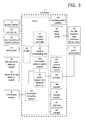
- FIG. 3 is an electrical block diagram of the pharmaceutical injection device in FIG.1 .
- the controller 7 is constituted by a microprocessor. As shown in FIG. 3 , a rechargeable battery 36 is connected to the controller 7 and other electrically driven parts. The electrical connection state of the rechargeable battery 36 and the other electrically driven parts is not shown, to keep FIG. 3 from being too complicated.
- a central processing unit 37 is provided inside the controller 7.
- the central processing unit 37 performs operational control over the various blocks shown in FIG. 3 .
- a program that performs this operational control is written into a ROM 38.
- An orientation detecting section 39, a piston movement distance sensor 40, and a motor rotation controller 41 are connected to the central processing unit 37.
- An orientation determination section 39a and the orientation sensor 8 are connected to the orientation detecting section 39.
- the orientation detecting section 39 converts the orientation sensing result from the orientation sensor 8 into information for determining the orientation at the orientation determination section 39a.
- the orientation determination section 39a performs various kinds of operational control according to the orientation, such as using the orientation information obtained from the orientation detecting section 39 to compare the inclination sensed by the orientation sensor 8 with a set value, determine whether or not to drive the piston drive motor 10, etc.
- the piston movement distance detector 40 is connected to the encoder 26.
- the encoder 26 is attached to the piston drive motor 10, which allows the movement distance of the piston 5 to be detected by detecting the rotation of the piston drive motor 10.
- the motor rotation controller 41 is connected to a motor drive circuit 42. When the value detected by the piston movement distance detector 40 reaches a preset value, the motor rotation controller 41 controls the motor drive circuit 42 to change the movement speed of the piston 5.
- the piston drive motor 10 and the needle insertion and retraction drive motor 12 are connected to the motor drive circuit 42.
- the motor drive circuit 42 is connected to an over-current detection circuit 43.
- the motor drive circuit 42 is controlled by the motor rotation controller 41 while driving the piston drive motor 10 and the needle insertion and retraction drive motor 12.
- the over-current detection circuit 43 is a circuit that detects the amount of current from the motor drive circuit 42, and detects malfunction of the motors.
- the controller 7 is also connected to a buzzer 44 and a vibrator 45 for issuing a warning so as to alert the user to the current usage status of the device.
- the controller 7 is also connected to the display section 35, which displays warnings and information for operating the device, and to a memory 51 for recording various kinds of data.
- the distal end cap detector switch 28 checks whether or not the distal end cap 23 has been mounted, as shown in S4. Here again, as shown in S5, if the distal end cap 23 has not been mounted, a warning display of "Please mount distal end cap" is given on the display section 35.
- the inclination of the pharmaceutical injection device is sensed by the orientation sensor 8.
- the inclination will be referred to by using the direction perpendicular to the horizontal plane as zero degrees. If the inclination exceeds a specific value (the set value), the operation is halted until the inclination falls back to within the specific value (the set value), and operation is restarted once the inclination has been within the specific value for a specific length of time.
- the inclination at which operation is performed it is preferable for the inclination at which operation is performed to be 30 degrees or less.
- the inclination is continuously sensed by the orientation sensor 8 during the operation from S7 onward as shown in FIG. 7 (S26).
- the piston drive motor 10 is stopped (S28), and the display section 35 gives a warning display of "Main body case is tilted too far. Operation has been stopped" (S29) and "Please put the tip facing up” (S30). This prompts the user not to tilt the main body case 2 more than 30 degrees.
- S31 is a loop with S30, and is used to check whether the inclination of the main body case 2 has exceeded 30 degrees.
- S32 is used to restart the operation prior to the stoppage and return to S8 in the event that it was sensed in S31 that the inclination was 30 degrees or less.
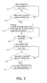
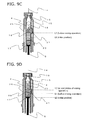
- the piston drive motor 10 is driven from its initial state prior to the mixing operation, at the push-in rate V1. Then, in S9, the movement distance of the piston 5 is calculated by the encoder 26 during drive of the piston 5. Then, in S10, the piston drive motor 10 continues to move at the push-in rate V1 until the rear end of the separation gasket 18 goes from L0 in FIG. 9B (the initial position) to the position L1 a specific distance away.
- L1 indicates the position where the rear end of the separation gasket 18 touches the bypass 21, and is position information about the movement distance from the initial position L0 to L1, that is, until the rear end of the separation gasket 18 changes from its initial state to a contact state. This movement distance L1 position information is stored ahead of time in the memory 51.
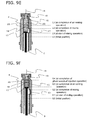
- the piston drive motor 10 continues to move at the push-in rate V2 until the distal end of the separation gasket 18 reaches the position L2 shown in FIG. 9D .
- the movement distance from the position L1 to the position L2, as shown in FIG. 9D is the movement distance up until the separation gasket 18 and the push-in gasket 17 come into contact, that is, it is the movement distance until the separation gasket 18 goes from its initial state to a state of being in contact with the push-in gasket 17.
- This L2 position information is stored ahead of time in the memory 51.
- the push-in rate V2 of the separation gasket 18 by the piston drive motor 10 is thus set to be lower than the push-in rate V1, it is less likely that there will be a sudden surge in pressure on the solid pharmaceutical 19 side when the liquid pharmaceutical 20 passes through the bypass 21. As a result, this prevents some of the liquid pharmaceutical from squirting out of the distal end of the injection needle 14 mounted to the distal end gasket 16 of the cylinder 15, or from overflowing more than necessary. That is, liquid leakage from the distal end of the injection needle 14 is also reduced during pharmaceutical mixing, so the mixing operation can be carried out more favorably.
- the display section 35 displays "Lightly shake the device and then angle the tip upward and press the end button" as shown in S13, and the operation of the piston drive motor 10 is temporarily halted. Also, the sensing of orientation is not carried out from the time of the above display until the end button 34 is pressed.
- the push-in rate of the separation gasket 18 by the piston drive motor 10 is switched to a push-in rate V3 so as to be lower than the push-in rate V1 (V3 ⁇ V1). More preferably, as in this embodiment, the push-in rate V3 is set to be lower than the push-in rate V2 (V3 ⁇ V2).
- the piston drive motor 10 is operated at the push-in rate V3 until the distal end position of the separation gasket 18 arrives at the position L3.
- the movement distance from the position L2 to the position L3 indicates the position after the separation gasket 18 and the push-in gasket 17 have passed through the bypass 21 in a state of being in contact with each other.
- Position information about the position L3 is stored ahead of time in the memory 51.
- the air venting operation is ended when the distal end position of the separation gasket 18 reaches the position L3.
- needle insertion and retraction drive motor 12 is driven to perform the needle insertion operation.
- This "needle insertion operation” refers to an operation of driving the needle insertion and retraction drive motor 12 to move the pharmaceutical syringe mounting portion 3 to the injection needle insertion and retraction opening 1 side, and thereby causing the injection needle 14 to stick out from the injection needle insertion and retraction opening 1.
- the injection needle 14 is moved toward the body and the injection needle 14 is plunged into the body, and the preparatory operation (needle insertion operation) prior to pharmaceutical injection is complete.
- the push-in rate of the separation gasket 18 by the piston drive motor 10 is switched to the push-in rate V4 so as to be higher than the push-in rate V3 (V4 > V3).
- the speed at which the piston 5 is moved can be increased.
- the movement distance from the position L3 to the position L4 indicates the movement distance up to where the separation gasket 18 reaches the inclined portion of the distal end of the pharmaceutical syringe 4. Position information about this movement distance L4 is stored ahead of time in the memory 51.
- the needle retraction operation is commenced when the distal end position of the separation gasket 18 reaches the position L4.
- the piston drive motor 10 is halted and the needle insertion and retraction drive motor 12 is driven.
- This needle retraction operation involves driving the needle insertion and retraction drive motor 12 to move the pharmaceutical syringe mounting portion 3 to the rear end side, and thereby stowing the injection needle 14 inside the injection needle insertion and retraction opening 1.
- FIG. 8 is a graph of the operating state during mixing with this pharmaceutical injection device.
- the vertical axis is the applied voltage (value) to a motor driver (not shown) for driving the piston drive motor 10, and the horizontal axis is the rear end position or distal end position of the separation gasket 18, showing a simulation of the flow of the operation at the above-mentioned push-in rates (V1, V2, V3, and V4).
- the push-in rates are determined by changing the voltage values of a piston speed control signal (such as 1.0 volt for V1 and V4, 0.8 volt for V2, and 0.7 volt for V3). It can be seen that as the piston 5 is moved, the push-in rate V2 when the liquid pharmaceutical 20 passes through the bypass 21 is lower than the initial push-in rate V1, the push-in rate V3 during air venting is lower than the push-in rate V2, and the push-in rate V4 during pharmaceutical injection is higher than the push-in rate V3.
- a piston speed control signal such as 1.0 volt for V1 and V4, 0.8 volt for V2, and 0.7 volt for V3
- the graph in FIG. 8 is just an example, and a waiting period for user manipulation selection can be allocated as needed, such as between V2 and V3, or between V3 and V4. In this case, the mixing operation can be temporarily halted so that the various speeds are all zero. This is generally how the settings are made.
- position information about L0, L1, L2, L3, and L4 indicated where the distal end position or rear end position of the separation gasket 18 was located within the pharmaceutical syringe 4, but the above-mentioned control may be accomplished with the movement distance of the piston 5 at a separate stage.
- the pharmaceutical injection device in this embodiment is such that in the pharmaceutical mixing operation, the push-in rate V2 at the point when the separation gasket 18 passes through the bypass 21 is set lower than the push-in rate V1 when the separation gasket 18 is pushed in until it comes into contact with the bypass 21. Consequently, the liquid pharmaceutical 20 flows gently through the bypass 21 to the solid pharmaceutical 19 side. As a result, leakage from the distal end gasket 16 side can be reduced during this pharmaceutical mixing operation, the surroundings can be kept clean, without the pharmaceutical splashing onto the surrounding area when the pharmaceutical injection device is operated by the user, and the automatic mixing of the pharmaceuticals can be carried out easily and safely.
- a main feature in this embodiment is that the display shown in FIG. 12 is displayed on the display section 35.
- the robots 46 to 50 shown in the bottom row are displayed as a finished product display on the display section 35.
- these robots 46 to 50 are chosen from among 78,125 finished products, as will be understood from the following explanation.
- one of the robots 46 to 50 is displayed as a finished product in seven days (one week), on the premise that pharmaceutical injection is performed once a day.
- the engineer who will build the robots 46 to 50 is chosen.
- the factory where they will be built is chosen.
- the legs of the robots 46 to 50 are chosen.
- the waists of the robots 46 to 50 are chosen.
- the chests of the robots 46 to 50 are chosen.
- the arms of the robots 46 to 50 are chosen.
- the heads of the robots 46 to 50 are chosen, and the display contents chosen on the third to seventh days are combined, so that one of the robots 46 to 50 shown in the bottom row of FIG. 12 is displayed as a finished product on the display section 35.
- FIGS. 10 and 11 are flowcharts illustrating this display on the display section 35, and the programs thereof are written to the ROM 38 in FIG. 3 .
- FIG. 10 shows the operation from S25 in FIG. 6 , and in S33, collection data from the last time is read from a part update area (not shown) within the memory 51 shown in FIG. 3 (this is one of the parts on the first to seventh days in FIG. 12 ).
- the last injection time is read from an injection history area (not shown) within the memory 51.
- the last collection data is displayed on the display section 35. That is, in this embodiment, the pharmaceutical is injected once a day, such as after dinner each day, but if it is anticipated that the pharmaceutical cannot be injected after the next dinner for some reason (such as because the user will be flying), then the user may have to inject the pharmaceutical a little earlier than scheduled. Nevertheless, it is preferable to perform the next pharmaceutical injection if at least 12 hours have elapsed since the last injection time. Thus, in S35, as discussed above, it is determined whether or not at least 12 hours have elapsed since the last injection time. This is also advantageous in a way that will now be described.
- S38 in FIG. 10 it is determined whether or not it has been more than seven days since the part data displayed on the display section 35 (the part data registered to the part update area in the memory 51) was acquired the first time. If seven days has not been exceeded, in S39 the part data shown in FIG. 12 and collected over the course of seven days is combined, and the robot shown in FIG. 12 (such as one of the robots 46 to 50) is displayed as a finished product on the display section 35 (S40 in FIG. 10 ). In S40, a display is given that asks the question of whether or not to save the robot displayed on the display section 35 (such as one of the robots 46 to 50).
- a selection is made as to whether or not to leave the robot displayed on the display section 35 (such as one of the robots 46 to 50) as part of a collection. If the selection is to leave the robot, then in S42 the finished product collection data is saved in the part storage area (not shown) of the memory 51. If the selection in S41 was not to leave the robot displayed on the display section 35 (such as one of the robots 46 to 50), then in S43 the finished product collection data is deleted from the part update area of the memory 51.
- FIG. 11 is a flowchart of the flow of operation when the completed collection data collected in the part storage area of the memory 51 (such as the robots 46 to 50 in FIG. 12 ) is displayed on the display section 35.
- a collection reference sub-menu is displayed on the display section 35
- a completed collection is selected from the sub-menu.
- the completed collection data is read from the part storage area in the memory 51, and in S53 the collected robots are sequentially displayed on the display section 35.
- S57 is a selection mode when the display of S53 and S56 is ended.
- parts may be deleted and taken apart to produce different data patterns, so that the display prompts the user to perform pharmaceutical injection.
- the pharmaceutical injection device of the present invention even if the user is a child, for example, he can enjoy performing pharmaceutical injection properly as scheduled, which has the effect of enhancing the therapeutic effect, so this device is expected to find widespread acceptance in fields such as pharmaceutical injection devices in which a pharmaceutical mixing operation is required.
Landscapes
- Health & Medical Sciences (AREA)
- Vascular Medicine (AREA)
- Engineering & Computer Science (AREA)
- Anesthesiology (AREA)
- Biomedical Technology (AREA)
- Heart & Thoracic Surgery (AREA)
- Hematology (AREA)
- Life Sciences & Earth Sciences (AREA)
- Animal Behavior & Ethology (AREA)
- General Health & Medical Sciences (AREA)
- Public Health (AREA)
- Veterinary Medicine (AREA)
- Infusion, Injection, And Reservoir Apparatuses (AREA)
Abstract
Description
- The present invention relates to a pharmaceutical injection device.
- A conventional pharmaceutical injection device comprised a main body case that had an injection needle insertion and retraction opening, a pharmaceutical syringe mounting portion provided within this main body case, a piston provided movably with respect to a pharmaceutical syringe that was mounted to this pharmaceutical syringe mounting portion, a drive mechanism for driving this piston, a controller that was electrically connected to this drive mechanism, and a display section that was electrically connected to this controller (see
Patent Literature 1, for example). - Patent Literature 1: Japanese Unexamined Patent Application Publication (Translation of PCT Application) No.
2004-516107 - However, the following problems were encountered with the conventional pharmaceutical injection device discussed above.
- Specifically, with the pharmaceutical injection device disclosed in the above-mentioned publication, after a pharmaceutical syringe has been mounted to the pharmaceutical syringe mounting portion provided within the main body case, the patient presses a pharmaceutical injection button, whereupon the drive mechanism drives the piston, and a specific amount of the pharmaceutical inside the pharmaceutical syringe is injected into the patient.
- In other words, with this type of pharmaceutical injection device, the patient himself is the one to inject the pharmaceutical into his own body by operating the device, and such devices are often used in injecting a growth hormone into a child. To continue the description while referring to this example, when a pharmaceutical injection device such as this is used, even a child can easily inject the proper dose of growth hormone all by himself.
- Nevertheless, although we have said that the user can "easily inject" the pharmaceutical, he still has to insert an injection needle into his body, and children in particular dislike this, which means that there is the risk that the user will not perform the pharmaceutical injections as scheduled. As a result, the therapeutic effect may be diminished.
- In view of this, it is an object of the present invention to provide a pharmaceutical injection device with which the therapeutic effect can be enhanced.
- To achieve the stated object, the present invention comprises a main body case, a pharmaceutical syringe mounting portion, a piston, a drive mechanism, a controller, and a display section. The main body case has an injection needle insertion and retraction opening. The pharmaceutical syringe mounting portion is provided within the main body case. The piston is provided movably with respect to a pharmaceutical syringe that is mounted to the pharmaceutical syringe mounting portion. The drive mechanism drives the piston. The controller is electrically connected to the drive mechanism. The display section is electrically connected to the controller. The controller updates the display content that is displayed on the display section according to the number of times the drive mechanism has been driven, and saves the updated display content in a memory, so that when the number of times the drive mechanism has been driven reaches a specific number, the display contents during the various instances of drive that were saved in the memory are combined.
- With the pharmaceutical injection device pertaining to the present invention, the controller updates the display content that is displayed on the display section according to the number of times the drive mechanism has been driven, and saves the updated display content in a memory. Then, when the drive mechanism has been driven a specific number of times, the controller combines at least a plurality of the display contents during the various instances that were saved in the memory. Consequently, the display content is updated every time the pharmaceutical is injected, and when the number of times the drive mechanism has been driven reaches a specific number of times, at least a plurality of the display contents during the various instances saved in the memory are combined, and a finished product display is given.
- Accordingly, even a child, for example, can actually enjoy performing the pharmaceutical injections as scheduled, and as a result the therapeutic effect can be enhanced.
-
-
FIG. 1 is an oblique view of the pharmaceutical injection device pertaining to an embodiment of the present invention; -
FIG. 2 is a cross section of the pharmaceutical injection device inFIG. 1 ; -
FIG. 3 is a control block diagram of the simplified electrical configuration of the pharmaceutical injection device inFIG. 1 ; -
FIG. 4 is a flowchart of the operational control of the pharmaceutical injection device inFIG. 1 ; -
FIG. 5 is a flowchart of the operational control of the pharmaceutical injection device inFIG. 1 ; -
FIG. 6 is a flowchart of the operational control of the pharmaceutical injection device inFIG. 1 ; -
FIG. 7 is a flowchart of the operational control of the pharmaceutical injection device inFIG. 1 ; -
FIG. 8 is a graph of the operating state during mixing in the pharmaceutical injection device inFIG. 1 ; -
FIG. 9A is a cross section of the operating state during mixing in the pharmaceutical injection device pertaining inFIG. 1 ; -
FIG. 9B is a cross section of the operating state during mixing in the pharmaceutical injection device pertaining inFIG. 1 ; -
FIG. 9C is a cross section of the operating state during mixing in the pharmaceutical injection device pertaining inFIG. 1 ; -
FIG. 9D is a cross section of the operating state during mixing in the pharmaceutical injection device pertaining inFIG. 1 ; -
FIG. 9E is a cross section of the operating state during mixing in the pharmaceutical injection device pertaining inFIG. 1 ; -
FIG. 9F is a cross section of the operating state during mixing in the pharmaceutical injection device pertaining inFIG. 1 ; -
FIG. 10 is a flowchart of the operational control of the pharmaceutical injection device inFIG. 1 ; -
FIG. 11 is a flowchart of the operational control of the pharmaceutical injection device inFIG. 1 ; and -
FIG. 12 is a diagram of the operational control of the pharmaceutical injection device inFIG. 1 . - Embodiments of the present invention will now be described through reference to the appended drawings.
- As shown in
FIGS. 1 and 2 , the pharmaceutical injection device in this embodiment comprises a substantially cylindricalmain body case 2, a pharmaceuticalsyringe mounting portion 3, apharmaceutical syringe 4, apiston 5, adrive mechanism 6, acontroller 7, and anorientation sensor 8. Themain body case 2 has an injection needle insertion and retraction opening 1 on its distal end side. The pharmaceuticalsyringe mounting portion 3 is provided within themain body case 2. Thepharmaceutical syringe 4 is mounted within the pharmaceuticalsyringe mounting portion 3. Thepiston 5 is provided movably with respect to thepharmaceutical syringe 4. Thedrive mechanism 6 drives thepiston 5. Thecontroller 7 is electrically connected to thedrive mechanism 6. Theorientation sensor 8 is electrically connected to thecontroller 7. - The
orientation sensor 8 is mounted on a substrate 7a having thecontroller 7. The substrate 7a is installed so as to be parallel to the drive direction of thepiston 5. - The
drive mechanism 6 is made up of a bolt 9 inserted into a rear end opening in thepiston 5, and apiston drive motor 10 for driving the bolt 9. Specifically, when thepiston drive motor 10 is rotated in one direction, the bolt 9 pushes thepiston 5 toward the injection needle insertion andretraction opening 1. Conversely, and when thepiston drive motor 10 is rotated in the other direction, thepiston 5 is pulled back toward thepiston drive motor 10. - The
piston drive motor 10 and thepiston 5 are disposed along with thepharmaceutical syringe 4 inside the pharmaceuticalsyringe mounting portion 3.Female threads 11 are provided toward the outside of the rear end side of the pharmaceuticalsyringe mounting portion 3. A bolt 13 of a needle insertion and retraction drivemotor 12 meshes with thesefemale threads 11. That is, when the needle insertion and retraction drivemotor 12 is driven, thefemale threads 11 and the bolt 13 mesh, causing the pharmaceuticalsyringe mounting portion 3 to move back and forth with respect to the injection needle insertion andretraction opening 1. This causes aninjection needle 14 provided on the distal end side of thepharmaceutical syringe 4 to come out of the injection needle insertion andretraction opening 1. - As shown in
FIG. 9A , thepharmaceutical syringe 4 has acylinder 15, adistal end gasket 16, a push-ingasket 17, aseparation gasket 18, asolid pharmaceutical 19, aliquid pharmaceutical 20, and abypass 21. Thedistal end gasket 16 is provided on the distal end side within thecylinder 15. The push-ingasket 17 is provided on the rear end side within thecylinder 15. Theseparation gasket 18 is provided in the middle within thecylinder 15. Thesolid pharmaceutical 19 is contained inside thecylinder 15 between thedistal end gasket 16 and theseparation gasket 18. Theliquid pharmaceutical 20 is contained inside thecylinder 15 between the push-ingasket 17 and theseparation gasket 18. Thebypass 21 protrudes in the outer peripheral direction of thecylinder 15 at the portion of thecylinder 15 between thedistal end gasket 16 and theseparation gasket 18. - The
controller 7 actuates thedrive mechanism 6 so that the push-ingasket 17 is pressed by thepiston 5 to thedistal end gasket 16 side after orientation and position sensing by theorientation sensor 8. - Also, the rate at which the push-in
gasket 17 is pushed in by thepiston 5 is set so that if we let V1 be the push-in rate when theseparation gasket 18 reaches thebypass 21, V2 be the push-in rate at the point when theseparation gasket 18 goes through thebypass 21, V3 be the push-in rate at the point when air is vented after theseparation gasket 18 has gone through thebypass 21, and V4 be the push-in rate at the point when a pharmaceutical is injected after air venting, the push-in rate V2 will be lower than the push-in rate V1. - Returning to
FIGS. 1 and 2 , themain body case 2 is made up of ahousing 22 and adistal end cap 23 on the distal end side of thehousing 22. Thedistal end cap 23 is removably attached to thehousing 22, and awindow 24 is provided on the outer peripheral part of thedistal end cap 23. - After the
pharmaceutical syringe 4 has been mounted inside the pharmaceuticalsyringe mounting portion 3, the outer periphery of thepharmaceutical syringe 4 is covered by a syringe cover 25 (seeFIG. 9A , etc.), and in this state, theinjection needle 14 is mounted to thedistal end gasket 16 on the distal end side of thepharmaceutical syringe 4. - When the
piston 5 pushes the push-ingasket 17 forward, theliquid pharmaceutical 20 goes through thebypass 21 and flows to the solid pharmaceutical 19 side, and when the push-ingasket 17 moves farther forward, the liquid pharmaceutical 20 flows out of theinjection needle 14. - The rotation of the
piston drive motor 10 is detected by anencoder 26. Consequently, the amount by which thepiston 5 protrudes (moves) is sensed. Thesolid pharmaceutical 19 and the liquid pharmaceutical 20 contained inside thepharmaceutical syringe 4 are put in at a pharmaceutical company, etc. - The
housing 22 of themain body case 2 also houses a number of switches. More specifically, a distal endcap detector switch 28 is disposed at the rear end of acontrol rod 27 provided around the outer periphery of the pharmaceuticalsyringe mounting portion 3, on the distal end side of thehousing 22. When thedistal end cap 23 is mounted to the distal end of thehousing 22, thecontrol rod 27 is pushed rearward, and the distal endcap detector switch 28 detects that thedistal end cap 23 has been mounted. - A
control rod 29 is disposed inside the pharmaceuticalsyringe mounting portion 3. When thecontrol rod 29 is pushed rearward by thesyringe cover 25, a syringecover detector switch 30 detects that thesyringe cover 25 has been mounted. - The
orientation sensor 8 is mounted on the substrate 7a having thecontroller 7. Since the substrate 7a is installed so as to be parallel to the drive direction of thepiston 5, theorientation sensor 8 can properly sense acceleration with respect to themain body case 2. In this embodiment, the substrate 7a is installed parallel to the drive direction of thepiston 5, but may instead be installed perpendicular to the drive direction of thepiston 5. - Returning to
FIG. 1 , various control buttons and so forth are provided to the outer periphery of thehousing 22 of themain body case 2. More specifically, apower button 31 is provided to the rear end of thehousing 22. Amix button 32, apharmaceutical injection button 33, anend button 34, and adisplay section 35 are provided to the outer periphery of thehousing 22. -
FIG. 3 is an electrical block diagram of the pharmaceutical injection device inFIG.1 . - The
controller 7 is constituted by a microprocessor. As shown inFIG. 3 , arechargeable battery 36 is connected to thecontroller 7 and other electrically driven parts. The electrical connection state of therechargeable battery 36 and the other electrically driven parts is not shown, to keepFIG. 3 from being too complicated. - A
central processing unit 37 is provided inside thecontroller 7. Thecentral processing unit 37 performs operational control over the various blocks shown inFIG. 3 . A program that performs this operational control is written into aROM 38. Anorientation detecting section 39, a pistonmovement distance sensor 40, and amotor rotation controller 41 are connected to thecentral processing unit 37. - An
orientation determination section 39a and theorientation sensor 8 are connected to theorientation detecting section 39. Theorientation detecting section 39 converts the orientation sensing result from theorientation sensor 8 into information for determining the orientation at theorientation determination section 39a. - The
orientation determination section 39a performs various kinds of operational control according to the orientation, such as using the orientation information obtained from theorientation detecting section 39 to compare the inclination sensed by theorientation sensor 8 with a set value, determine whether or not to drive thepiston drive motor 10, etc. - The piston
movement distance detector 40 is connected to theencoder 26. Theencoder 26 is attached to thepiston drive motor 10, which allows the movement distance of thepiston 5 to be detected by detecting the rotation of thepiston drive motor 10. - The
motor rotation controller 41 is connected to amotor drive circuit 42. When the value detected by the pistonmovement distance detector 40 reaches a preset value, themotor rotation controller 41 controls themotor drive circuit 42 to change the movement speed of thepiston 5. - The
piston drive motor 10 and the needle insertion and retraction drivemotor 12 are connected to themotor drive circuit 42. Themotor drive circuit 42 is connected to anover-current detection circuit 43. - The
motor drive circuit 42 is controlled by themotor rotation controller 41 while driving thepiston drive motor 10 and the needle insertion and retraction drivemotor 12. - The
over-current detection circuit 43 is a circuit that detects the amount of current from themotor drive circuit 42, and detects malfunction of the motors. - The
controller 7 is also connected to abuzzer 44 and avibrator 45 for issuing a warning so as to alert the user to the current usage status of the device. - The
controller 7 is also connected to thedisplay section 35, which displays warnings and information for operating the device, and to amemory 51 for recording various kinds of data. - The above configuration will now be described through reference to the operational flowchart shown in
FIG. 4 . - First, as shown in
FIG. 4 , in S1 themix button 32 is pressed (seeFIG. 1 ). Then, in S2 the syringecover detector switch 30 detects whether or not thesyringe cover 25 has been mounted. If thesyringe cover 25 has not been mounted, as shown in S3, a warning display of "Please mount syringe cover" is given on the display section 35 (seeFIG. 1 ). - Once the mounting of the
syringe cover 25 has been confirmed, the distal endcap detector switch 28 checks whether or not thedistal end cap 23 has been mounted, as shown in S4. Here again, as shown in S5, if thedistal end cap 23 has not been mounted, a warning display of "Please mount distal end cap" is given on thedisplay section 35. - The following operation is not performed if the
syringe cover 25 and thedistal end cap 23 have not been mounted, as shown in S2 and S4. - In S2 and S4, once it has been confirmed that the
syringe cover 25 and thedistal end cap 23 have been mounted, a display of "Please put tip facing up" is left on thedisplay section 35 for a specific length of time. - In S7, the inclination of the pharmaceutical injection device is sensed by the
orientation sensor 8. Hereinafter, the inclination will be referred to by using the direction perpendicular to the horizontal plane as zero degrees. If the inclination exceeds a specific value (the set value), the operation is halted until the inclination falls back to within the specific value (the set value), and operation is restarted once the inclination has been within the specific value for a specific length of time. When leakage from the injection needle is taken into account, it is preferable for the inclination at which operation is performed to be 30 degrees or less. - Although not discussed in detail here, the inclination is continuously sensed by the
orientation sensor 8 during the operation from S7 onward as shown inFIG. 7 (S26). Here, if the inclination of themain body case 2 exceeds 30 degrees (S27), thepiston drive motor 10 is stopped (S28), and thedisplay section 35 gives a warning display of "Main body case is tilted too far. Operation has been stopped" (S29) and "Please put the tip facing up" (S30). This prompts the user not to tilt themain body case 2 more than 30 degrees. S31 is a loop with S30, and is used to check whether the inclination of themain body case 2 has exceeded 30 degrees. - S32 is used to restart the operation prior to the stoppage and return to S8 in the event that it was sensed in S31 that the inclination was 30 degrees or less.
- In S8, as shown in
FIG. 9A , thepiston drive motor 10 is driven from its initial state prior to the mixing operation, at the push-in rate V1. Then, in S9, the movement distance of thepiston 5 is calculated by theencoder 26 during drive of thepiston 5. Then, in S10, thepiston drive motor 10 continues to move at the push-in rate V1 until the rear end of theseparation gasket 18 goes from L0 inFIG. 9B (the initial position) to the position L1 a specific distance away. As shown inFIG. 9B , L1 indicates the position where the rear end of theseparation gasket 18 touches thebypass 21, and is position information about the movement distance from the initial position L0 to L1, that is, until the rear end of theseparation gasket 18 changes from its initial state to a contact state. This movement distance L1 position information is stored ahead of time in thememory 51. - When the rear end of the
separation gasket 18 reaches the position L1, the mixing operation commences. As shown in S11 inFIG. 5 , the push-in rate V2 of the separation gasket by thepiston drive motor 10 is switched so as to be lower than the push-in rate V1 (V2 <V1). - As shown in
FIG. 9C , when the rear end of theseparation gasket 18 starts to pass through thebypass 21, theliquid pharmaceutical 20 begins to flow through thebypass 21 to the solid pharmaceutical 19 side. - Then, in S12, the
piston drive motor 10 continues to move at the push-in rate V2 until the distal end of theseparation gasket 18 reaches the position L2 shown inFIG. 9D . The movement distance from the position L1 to the position L2, as shown inFIG. 9D , is the movement distance up until theseparation gasket 18 and the push-ingasket 17 come into contact, that is, it is the movement distance until theseparation gasket 18 goes from its initial state to a state of being in contact with the push-ingasket 17. This L2 position information is stored ahead of time in thememory 51. - Because the push-in rate V2 of the
separation gasket 18 by thepiston drive motor 10 is thus set to be lower than the push-in rate V1, it is less likely that there will be a sudden surge in pressure on the solid pharmaceutical 19 side when the liquid pharmaceutical 20 passes through thebypass 21. As a result, this prevents some of the liquid pharmaceutical from squirting out of the distal end of theinjection needle 14 mounted to thedistal end gasket 16 of thecylinder 15, or from overflowing more than necessary. That is, liquid leakage from the distal end of theinjection needle 14 is also reduced during pharmaceutical mixing, so the mixing operation can be carried out more favorably. - Next, as shown in
FIG. 9D , when the distal end position of theseparation gasket 18 reaches the position L2, thedisplay section 35 displays "Lightly shake the device and then angle the tip upward and press the end button" as shown in S13, and the operation of thepiston drive motor 10 is temporarily halted. Also, the sensing of orientation is not carried out from the time of the above display until theend button 34 is pressed. - Next, in S14, air venting starts when the
end button 34 is pressed (seeFIG. 1 ). - In the air venting operation, while the inclination is being sensed by the
orientation sensor 8, the push-in rate of theseparation gasket 18 by thepiston drive motor 10 is switched to a push-in rate V3 so as to be lower than the push-in rate V1 (V3 < V1). More preferably, as in this embodiment, the push-in rate V3 is set to be lower than the push-in rate V2 (V3 < V2). - In S15, since liquid is most apt to leak from the distal end of the
injection needle 14 during the air venting operation, the speed at which thepiston 5 is moved is further lowered. - Then, in S16, the
piston drive motor 10 is operated at the push-in rate V3 until the distal end position of theseparation gasket 18 arrives at the position L3. As shown inFIG. 9E , the movement distance from the position L2 to the position L3 indicates the position after theseparation gasket 18 and the push-ingasket 17 have passed through thebypass 21 in a state of being in contact with each other. Position information about the position L3 is stored ahead of time in thememory 51. - As shown in S17, the air venting operation is ended when the distal end position of the
separation gasket 18 reaches the position L3. - The pharmaceutical injection operation shown in S18 in
FIG. 6 is then commenced. - When the automatic mixing and air venting operation discussed above is complete, in S19 the
display section 35 display a message of "Ready for injection. Place tip against skin and press pharmaceutical injection button" and the operation of thepiston drive motor 10 is temporarily halted. - Next, in S20, the operation of piercing the skin is commenced when the
pharmaceutical injection button 33 is pressed. - Next, in S21, the needle insertion and retraction drive
motor 12 is driven to perform the needle insertion operation. This "needle insertion operation" refers to an operation of driving the needle insertion and retraction drivemotor 12 to move the pharmaceuticalsyringe mounting portion 3 to the injection needle insertion andretraction opening 1 side, and thereby causing theinjection needle 14 to stick out from the injection needle insertion andretraction opening 1. - At this point, since the injection needle insertion and
retraction opening 1 is already being pressed against the site on the body where the injection is to be made, theinjection needle 14 is moved toward the body and theinjection needle 14 is plunged into the body, and the preparatory operation (needle insertion operation) prior to pharmaceutical injection is complete. - Then, in S22, when the preparatory operation (needle insertion operation) prior to pharmaceutical injection is complete, the operation of pharmaceutical injection is commenced.
- In the pharmaceutical injection operation, the push-in rate of the
separation gasket 18 by thepiston drive motor 10 is switched to the push-in rate V4 so as to be higher than the push-in rate V3 (V4 > V3). - Since it is unlikely that there will be leakage from the distal end of the
injection needle 14 during the pharmaceutical injection operation, the speed at which thepiston 5 is moved can be increased. - Then, in S23, the
piston drive motor 10 continues to move at the push-in rate V4 until the distal end position of theseparation gasket 18 reaches the position L4. - As shown in
FIG. 9F , the movement distance from the position L3 to the position L4 indicates the movement distance up to where theseparation gasket 18 reaches the inclined portion of the distal end of thepharmaceutical syringe 4. Position information about this movement distance L4 is stored ahead of time in thememory 51. - Finally, in S24, the needle retraction operation is commenced when the distal end position of the
separation gasket 18 reaches the position L4. In the needle retraction operation, thepiston drive motor 10 is halted and the needle insertion and retraction drivemotor 12 is driven. - This needle retraction operation involves driving the needle insertion and retraction drive
motor 12 to move the pharmaceuticalsyringe mounting portion 3 to the rear end side, and thereby stowing theinjection needle 14 inside the injection needle insertion andretraction opening 1. - After this, in S25, when the pharmaceutical
syringe mounting portion 3 reaches its initial position prior to the needle insertion operation, the needle retraction operation is complete, and the operation of pharmaceutical injection into the body is ended. -
FIG. 8 is a graph of the operating state during mixing with this pharmaceutical injection device. The vertical axis is the applied voltage (value) to a motor driver (not shown) for driving thepiston drive motor 10, and the horizontal axis is the rear end position or distal end position of theseparation gasket 18, showing a simulation of the flow of the operation at the above-mentioned push-in rates (V1, V2, V3, and V4). - Although not discussed detail here, the push-in rates are determined by changing the voltage values of a piston speed control signal (such as 1.0 volt for V1 and V4, 0.8 volt for V2, and 0.7 volt for V3). It can be seen that as the
piston 5 is moved, the push-in rate V2 when the liquid pharmaceutical 20 passes through thebypass 21 is lower than the initial push-in rate V1, the push-in rate V3 during air venting is lower than the push-in rate V2, and the push-in rate V4 during pharmaceutical injection is higher than the push-in rate V3. - The graph in
FIG. 8 is just an example, and a waiting period for user manipulation selection can be allocated as needed, such as between V2 and V3, or between V3 and V4. In this case, the mixing operation can be temporarily halted so that the various speeds are all zero. This is generally how the settings are made. - In the above description, position information about L0, L1, L2, L3, and L4 indicated where the distal end position or rear end position of the
separation gasket 18 was located within thepharmaceutical syringe 4, but the above-mentioned control may be accomplished with the movement distance of thepiston 5 at a separate stage. - As discussed above, the pharmaceutical injection device in this embodiment is such that in the pharmaceutical mixing operation, the push-in rate V2 at the point when the
separation gasket 18 passes through thebypass 21 is set lower than the push-in rate V1 when theseparation gasket 18 is pushed in until it comes into contact with thebypass 21. Consequently, the liquid pharmaceutical 20 flows gently through thebypass 21 to the solid pharmaceutical 19 side. As a result, leakage from thedistal end gasket 16 side can be reduced during this pharmaceutical mixing operation, the surroundings can be kept clean, without the pharmaceutical splashing onto the surrounding area when the pharmaceutical injection device is operated by the user, and the automatic mixing of the pharmaceuticals can be carried out easily and safely. - Next, the most salient features of this embodiment will be described.
- A main feature in this embodiment is that the display shown in
FIG. 12 is displayed on thedisplay section 35. - In
FIG. 12 , when pharmaceutical injection is performed properly for seven days, therobots 46 to 50 shown in the bottom row are displayed as a finished product display on thedisplay section 35. In this embodiment, theserobots 46 to 50 are chosen from among 78,125 finished products, as will be understood from the following explanation. - With the pharmaceutical injection device in this embodiment, one of the
robots 46 to 50, for example, is displayed as a finished product in seven days (one week), on the premise that pharmaceutical injection is performed once a day. First, on the first day, the engineer who will build therobots 46 to 50 is chosen. On the second day, the factory where they will be built is chosen. On the third day, the legs of therobots 46 to 50 are chosen. On the fourth day, the waists of therobots 46 to 50 are chosen. On the fifth day, the chests of therobots 46 to 50 are chosen. On the sixth day, the arms of therobots 46 to 50 are chosen. On the seventh day, the heads of therobots 46 to 50 are chosen, and the display contents chosen on the third to seventh days are combined, so that one of therobots 46 to 50 shown in the bottom row ofFIG. 12 is displayed as a finished product on thedisplay section 35. - As can be seen in this example, if there are five patterns put together in seven days, five to the seventh power gives a total of 78,125 possible finished products, so in actual usage, the same robot will never be displayed on the
display section 35. Since the engineer and factory on the first and second days are not combined with therobots 46 to 50, they will probably not affect the above-mentioned number of 78,125. In this embodiment, however, the engineer and factory can also affect the robot production by assigning attitudes (thoughts) about robot production to the engineer and the factory. As a result, it is possible to attached the above-mentioned 78,125 finished products. -
FIGS. 10 and11 are flowcharts illustrating this display on thedisplay section 35, and the programs thereof are written to theROM 38 inFIG. 3 . -
FIG. 10 shows the operation from S25 inFIG. 6 , and in S33, collection data from the last time is read from a part update area (not shown) within thememory 51 shown inFIG. 3 (this is one of the parts on the first to seventh days inFIG. 12 ). - In S34, the last injection time is read from an injection history area (not shown) within the
memory 51. In S35, it is determined whether or not the current pharmaceutical injection is at least 12 hours after the last injection time. In S35 here, if at least 12 hours have elapsed since the last injection time, then a part matching the current number of days (the n-th day) shown inFIG. 12 is selected in S36. The selected part is recorded to the part update area (not shown) in thememory 51. - On the other hand, in S35, if at least 12 hours have not elapsed since the last injection time, then the last collection data is displayed on the
display section 35. That is, in this embodiment, the pharmaceutical is injected once a day, such as after dinner each day, but if it is anticipated that the pharmaceutical cannot be injected after the next dinner for some reason (such as because the user will be flying), then the user may have to inject the pharmaceutical a little earlier than scheduled. Nevertheless, it is preferable to perform the next pharmaceutical injection if at least 12 hours have elapsed since the last injection time. Thus, in S35, as discussed above, it is determined whether or not at least 12 hours have elapsed since the last injection time. This is also advantageous in a way that will now be described. - Specifically, even if the user should inadvertently perform pharmaceutical injection just to see the
robots 46 to 50 shown inFIG. 12 , unless at least 12 hours have elapsed since the last pharmaceutical injection, the collection data acquired the last time (data for one of the parts from the first to seventh days inFIG. 12 ) will merely be displayed again, that is, there will be no update (S37 inFIG. 10 ). Inadvertent pharmaceutical injection can thus be avoided. - Next, in S38 in
FIG. 10 , it is determined whether or not it has been more than seven days since the part data displayed on the display section 35 (the part data registered to the part update area in the memory 51) was acquired the first time. If seven days has not been exceeded, in S39 the part data shown inFIG. 12 and collected over the course of seven days is combined, and the robot shown inFIG. 12 (such as one of therobots 46 to 50) is displayed as a finished product on the display section 35 (S40 inFIG. 10 ). In S40, a display is given that asks the question of whether or not to save the robot displayed on the display section 35 (such as one of therobots 46 to 50). - In S41, a selection is made as to whether or not to leave the robot displayed on the display section 35 (such as one of the
robots 46 to 50) as part of a collection. If the selection is to leave the robot, then in S42 the finished product collection data is saved in the part storage area (not shown) of thememory 51. If the selection in S41 was not to leave the robot displayed on the display section 35 (such as one of therobots 46 to 50), then in S43 the finished product collection data is deleted from the part update area of thememory 51. - Also, if the finished product collection data stored in the part storage area (not shown) of the
memory 51 is deleted in S42, the flow proceeds to S43. - Then, in S44 the pharmaceutical injection operation is concluded.
- Meanwhile, in S38, it is determined that pharmaceutical injection has been properly performed for seven days in a row if it has been more than seven days since the part data displayed on the display section 35 (the part data registered to the part update area of the memory 51) was acquired the first time, and in S45 a display is given on the
display section 35 indicating that not all of the parts were collected within the time frame. After this, in S43, the finished product collection data is deleted from the part update area of thememory 51. That is, if pharmaceutical injection has not been properly performed for seven days in a row, the robot shown inFIG. 12 (such as one of therobots 46 to 50) cannot be displayed on thedisplay section 35. Because the user is thus persuaded to avoid this, pharmaceutical injection can be performed properly for seven days in a row and its therapeutic effect enhanced. - In S39, it is determined whether or not the parts collection is complete this time. If seven days' worth of parts have not been collected, in S46 the collection data is saved in the part update area of the
memory 51, and in S44 the pharmaceutical injection operation is ended. If the next pharmaceutical injection is then performed, the operation will resume from S33. -
FIG. 11 is a flowchart of the flow of operation when the completed collection data collected in the part storage area of the memory 51 (such as therobots 46 to 50 inFIG. 12 ) is displayed on thedisplay section 35. - That is, in this embodiment, since there are 78,125 possibilities for robots that can be the finished product, what is of interest to the patient is which robots have been collected so far, and this also needs to be displayed sequentially.
- First, in S47, the referral to this collection is commenced.
- Then, in S48, a menu screen is displayed on the
display section 35. - Then, in S49, a collection reference is selected on the menu screen of the
display section 35. - Then, in S50, a collection reference sub-menu is displayed on the
display section 35, in S51 a completed collection is selected from the sub-menu. Then, in S52 the completed collection data is read from the part storage area in thememory 51, and in S53 the collected robots are sequentially displayed on thedisplay section 35. - Meanwhile, from S50 to S54, if a collection reference that is being updated is selected from the sub-menu, in S55 data that has been collected so far, that is, data from the first to sixth days in
FIG. 12 , is read from the part update area of thememory 51. - Then, in S56, the part collection is displayed on the
display section 35. - S57 is a selection mode when the display of S53 and S56 is ended.
- In this embodiment, the operations of performing selection and so forth in
FIGS. 10 and11 were all described in S48, for example, but since a menu screen is displayed on thedisplay section 35, these are executed by selecting options from that menu screen. - Also, in this embodiment, it was described that a plurality of parts are combined according to the results of pharmaceutical injection, and a robot finished product is displayed on a display section, but the present invention is not limited to this.
- For example, instead of combining a plurality of parts to complete a robot or other such character, parts may be deleted and taken apart to produce different data patterns, so that the display prompts the user to perform pharmaceutical injection.
- With the pharmaceutical injection device of the present invention, even if the user is a child, for example, he can enjoy performing pharmaceutical injection properly as scheduled, which has the effect of enhancing the therapeutic effect, so this device is expected to find widespread acceptance in fields such as pharmaceutical injection devices in which a pharmaceutical mixing operation is required.
-
- 1
- injection needle insertion and retraction opening
- 2
- main body case
- 3
- pharmaceutical syringe mounting portion
- 4
- pharmaceutical syringe
- 5
- piston
- 6
- drive mechanism
- 7
- controller
- 7a
- substrate
- 8
- orientation sensor
- 9
- bolt
- 10
- piston drive motor
- 11
- female threads
- 12
- needle insertion and retraction drive motor
- 13
- bolt
- 14
- injection needle
- 15
- cylinder
- 16
- distal end gasket
- 17
- push-in gasket
- 18
- separation gasket
- 19
- solid pharmaceutical
- 20
- liquid pharmaceutical
- 21
- bypass
- 22
- housing
- 23
- distal end cap
- 24
- window
- 25
- cylinder cover
- 26
- encoder
- 27
- control rod
- 28
- distal end cap detector switch
- 29
- control rod
- 30
- syringe cover detector switch
- 31
- power button
- 32
- mix button
- 33
- pharmaceutical injection button
- 34
- end button
- 35
- display section
- 36
- rechargeable battery
- 37
- central processing unit
- 38
- ROM
- 39
- orientation detecting section
- 39a
- orientation determination section
- 40
- piston movement distance detector
- 41
- motor rotation controller
- 42
- motor drive circuit
- 43
- over-current detection circuit
- 44
- buzzer
- 45
- vibrator
- 46, 47, 48, 49, 50
- robot
- 51
- memory
Claims (8)
- A pharmaceutical injection device, comprising:a main body case that has an injection needle insertion and retraction opening;a pharmaceutical syringe mounting portion that is provided within the main body case;a piston that is provided movably with respect to a pharmaceutical syringe mounted to the pharmaceutical syringe mounting portion;a drive mechanism configured to drive the piston;a controller that is electrically connected to the drive mechanism; anda display section that is electrically connected to the controller,wherein the controller updates the display content displayed on the display section according to the number of times the drive mechanism has been driven, and saves the updated display content in a memory, so that when the number of times the drive mechanism has been driven reaches a specific number, the display contents during the various instances of drive that were saved in the memory are combined.
- The pharmaceutical injection device according to Claim 1,
wherein, when the number of times the drive mechanism has been driven reaches a specific number, the controller combines the display contents for the various instances of drive that were saved in the memory, to give a finished product display. - The pharmaceutical injection device according to Claim 1 or 2,
wherein, when the drive mechanism is driven again within a specific length of time, the controller puts the display content displayed on the display section in a non-updated state. - The pharmaceutical injection device according to Claim 3,
wherein, when the drive mechanism is driven again within a specific length of time, the controller displays the display content from the previous update. - The pharmaceutical injection device according to any of Claims 1 to 4,
wherein, when the number of times the drive mechanism has been driven within a specific length of time does not reach a specific number, the controller causes the display section to display a message to the effect that a finished product display in which the display contents for the various instances of drive are combined cannot be given. - The pharmaceutical injection device according to Claim 5,
wherein, when the number of times the drive mechanism has been driven within a specific length of time does not reach a specific number, the controller deletes the display content saved in the memory. - The pharmaceutical injection device according to any of Claims 1 to 6,
wherein the controller saves in the memory a finished product display obtained by combining the display contents for the various instances of drive. - The pharmaceutical injection device according to Claim 7,
wherein the controller selectively displays the finished product display saved in the memory, and the display content from the last update.
Applications Claiming Priority (2)
| Application Number | Priority Date | Filing Date | Title |
|---|---|---|---|
| JP2011198101 | 2011-09-12 | ||
| PCT/JP2012/005710 WO2013038639A1 (en) | 2011-09-12 | 2012-09-10 | Drug injection device |
Publications (3)
| Publication Number | Publication Date |
|---|---|
| EP2756858A1 true EP2756858A1 (en) | 2014-07-23 |
| EP2756858A4 EP2756858A4 (en) | 2015-02-18 |
| EP2756858B1 EP2756858B1 (en) | 2017-06-14 |
Family
ID=47882890
Family Applications (1)
| Application Number | Title | Priority Date | Filing Date |
|---|---|---|---|
| EP12831039.8A Active EP2756858B1 (en) | 2011-09-12 | 2012-09-10 | Drug injection device |
Country Status (4)
| Country | Link |
|---|---|
| US (1) | US9526831B2 (en) |
| EP (1) | EP2756858B1 (en) |
| JP (1) | JP5764660B2 (en) |
| WO (1) | WO2013038639A1 (en) |
Families Citing this family (7)
| Publication number | Priority date | Publication date | Assignee | Title |
|---|---|---|---|---|
| US11872375B2 (en) | 2012-09-05 | 2024-01-16 | E3D Agricultural Cooperative Association Ltd. | Electronic auto-injection device |
| US9849221B2 (en) * | 2013-10-04 | 2017-12-26 | Flex Fluidics, Llc | Inline pump with rear attachable syringe |
| US20150246179A1 (en) * | 2014-03-02 | 2015-09-03 | Nissim Zur | Device and method for drug dosing with administration monitoring, in particular for insulin pen integrated with smart phone apps. |
| WO2015151900A1 (en) * | 2014-04-01 | 2015-10-08 | パナソニックヘルスケアホールディングス株式会社 | Drug injecting device, display control method for drug injecting device, and injection site display device |
| US20180015223A1 (en) * | 2014-12-19 | 2018-01-18 | Medaxor Pty Ltd | Multi-Use Injection System |
| WO2024077050A2 (en) * | 2022-10-06 | 2024-04-11 | Love Lifesciences Llc | Safety syringe systems, safety syringes, and methods of use |
| US20260007834A1 (en) * | 2024-07-05 | 2026-01-08 | Altek Biotechnology Corporation | Injection device |
Family Cites Families (22)
| Publication number | Priority date | Publication date | Assignee | Title |
|---|---|---|---|---|
| EP1002035A1 (en) | 1997-07-29 | 2000-05-24 | The Procter & Gamble Company | Concentrated, stable, preferably clear, fabric softening composition containing amine fabric softener |
| JP3261498B2 (en) | 1997-11-14 | 2002-03-04 | 株式会社カプコン | Portable game device and storage medium |
| US7214232B2 (en) | 1999-07-23 | 2007-05-08 | Ethicon, Inc. | Graft fixation device |
| US6585698B1 (en) | 1999-11-01 | 2003-07-01 | Becton, Dickinson & Company | Electronic medical delivery pen having a multifunction actuator |
| FR2809984B1 (en) | 2000-06-09 | 2006-07-14 | Aplix Sa | ROTARY SELOTRODE FOR CONTINUOUS WELDING ON LARGE WIDTH |
| AT409614B (en) | 2000-10-19 | 2002-09-25 | Freller Walter | BUNK ARRANGEMENT, IN PARTICULAR FOR TRANSPORT |
| IL156245A0 (en) | 2000-12-22 | 2004-01-04 | Dca Design Int Ltd | Drive mechanism for an injection device |
| JP2003309825A (en) | 2002-04-12 | 2003-10-31 | Kansai Telecasting Corp | Virtual living thing fostering system on data broadcasting |
| JP4017441B2 (en) | 2002-04-26 | 2007-12-05 | 三洋電機株式会社 | Organic EL panel and manufacturing method thereof |
| US7454458B2 (en) | 2002-06-24 | 2008-11-18 | Ntt Docomo, Inc. | Method and system for application load balancing |
| JP2004039165A (en) | 2002-07-05 | 2004-02-05 | Toshiba Corp | Optical pickup device, optical disk device, and tracking error signal detection method |
| WO2004006228A2 (en) | 2002-07-08 | 2004-01-15 | Academy Corporation | Reflective or semi-reflective metal alloy coatings |
| US6986865B2 (en) | 2002-07-10 | 2006-01-17 | Watlow Electric Manufacturing Company | Method for manufacturing an electrostatic chuck |
| US6879833B2 (en) | 2002-07-11 | 2005-04-12 | Sprint Spectrum L.P. | Method and system for vocoder bypass using differentiated telephone numbers |
| US20040007317A1 (en) | 2002-07-12 | 2004-01-15 | Chia-Hsiung Wu | Applying a hot melt band to paper sheet covering |
| US20070187899A1 (en) | 2006-02-14 | 2007-08-16 | Bush Peggy A | Interactive electronic display/game device that delivers aerosolized medication or other substance |
| US7892199B2 (en) * | 2007-05-21 | 2011-02-22 | Asante Solutions, Inc. | Occlusion sensing for an infusion pump |
| US8035221B2 (en) | 2007-11-08 | 2011-10-11 | Intersil Americas, Inc. | Clip mount for integrated circuit leadframes |
| CN102256644B (en) * | 2008-12-22 | 2015-04-29 | 松下健康医疗控股株式会社 | drug delivery device |
| US9446194B2 (en) * | 2009-03-27 | 2016-09-20 | Dexcom, Inc. | Methods and systems for promoting glucose management |
| EP2496421B1 (en) | 2009-07-31 | 2015-06-24 | Memjet Technology Limited | Printing system with fixed printheads and movable vacuum platen |
| WO2011108225A1 (en) * | 2010-03-01 | 2011-09-09 | パナソニック株式会社 | Medicine administering device |
-
2012
- 2012-09-10 US US14/343,493 patent/US9526831B2/en active Active
- 2012-09-10 EP EP12831039.8A patent/EP2756858B1/en active Active
- 2012-09-10 WO PCT/JP2012/005710 patent/WO2013038639A1/en not_active Ceased
- 2012-09-10 JP JP2013533488A patent/JP5764660B2/en active Active
Also Published As
| Publication number | Publication date |
|---|---|
| EP2756858A4 (en) | 2015-02-18 |
| WO2013038639A1 (en) | 2013-03-21 |
| US9526831B2 (en) | 2016-12-27 |
| JPWO2013038639A1 (en) | 2015-03-23 |
| EP2756858B1 (en) | 2017-06-14 |
| JP5764660B2 (en) | 2015-08-19 |
| US20140228763A1 (en) | 2014-08-14 |
Similar Documents
| Publication | Publication Date | Title |
|---|---|---|
| EP2756858B1 (en) | Drug injection device | |
| EP2756855B1 (en) | Drug injecting device | |
| US9289551B2 (en) | Pharmaceutical injection device | |
| EP2384778B1 (en) | Drug injection device with acceleration sensor | |
| US6726661B2 (en) | Air shot mechanism for electronic injection devices | |
| US9943647B2 (en) | Pharmaceutical injection device, method for controlling pharmaceutical injection device, and recording medium | |
| EP3127569B1 (en) | Pharmaceutical injection device, display control method for pharmaceutical injecting device, and injection site display device | |
| JP4282931B2 (en) | Air shot mechanism for electronic injection device | |
| SE432054B (en) | PROGRAMMABLE INJECTION AND INFUSION DEVICE | |
| EP3466465B1 (en) | Drug injection device | |
| JPWO2013038593A1 (en) | Drug injection device | |
| CN114832181A (en) | Infusion pump and interface operation method of infusion pump | |
| WO2023132104A1 (en) | Liquid drug administration device, method for controlling same, and liquid drug administration system | |
| US8696617B2 (en) | Portable drug administration device and method for controlling a portable drug administration device | |
| JP2769537B2 (en) | Control method of syringe pump | |
| JP6590464B2 (en) | Information display device, liquid feeding device including information display device, and control method of information display device | |
| CN118363512A (en) | Quick-forward interaction method of infusion device and infusion device |
Legal Events
| Date | Code | Title | Description |
|---|---|---|---|
| PUAI | Public reference made under article 153(3) epc to a published international application that has entered the european phase |
Free format text: ORIGINAL CODE: 0009012 |
|
| 17P | Request for examination filed |
Effective date: 20140227 |
|
| AK | Designated contracting states |
Kind code of ref document: A1 Designated state(s): AL AT BE BG CH CY CZ DE DK EE ES FI FR GB GR HR HU IE IS IT LI LT LU LV MC MK MT NL NO PL PT RO RS SE SI SK SM TR |
|
| A4 | Supplementary search report drawn up and despatched |
Effective date: 20150119 |
|
| RIC1 | Information provided on ipc code assigned before grant |
Ipc: A61M 5/315 20060101ALI20150113BHEP Ipc: G06F 19/00 20110101ALI20150113BHEP Ipc: A61M 5/20 20060101AFI20150113BHEP |
|
| REG | Reference to a national code |
Ref country code: DE Ref legal event code: R079 Ref document number: 602012033521 Country of ref document: DE Free format text: PREVIOUS MAIN CLASS: A61M0005200000 Ipc: A61M0005240000 |
|
| RIC1 | Information provided on ipc code assigned before grant |
Ipc: A61M 5/24 20060101AFI20161215BHEP Ipc: A61M 5/31 20060101ALI20161215BHEP Ipc: A61M 5/315 20060101ALI20161215BHEP Ipc: G06F 19/00 20110101ALI20161215BHEP Ipc: A61M 5/20 20060101ALI20161215BHEP |
|
| GRAP | Despatch of communication of intention to grant a patent |
Free format text: ORIGINAL CODE: EPIDOSNIGR1 |
|
| INTG | Intention to grant announced |
Effective date: 20170124 |
|
| RIN1 | Information on inventor provided before grant (corrected) |
Inventor name: KIKUCHI, SEIJI Inventor name: HANADA, TAKASHI Inventor name: KONDOH, TSUGUHIRO |
|
| GRAS | Grant fee paid |
Free format text: ORIGINAL CODE: EPIDOSNIGR3 |
|
| GRAA | (expected) grant |
Free format text: ORIGINAL CODE: 0009210 |
|
| AK | Designated contracting states |
Kind code of ref document: B1 Designated state(s): AL AT BE BG CH CY CZ DE DK EE ES FI FR GB GR HR HU IE IS IT LI LT LU LV MC MK MT NL NO PL PT RO RS SE SI SK SM TR |
|
| REG | Reference to a national code |
Ref country code: GB Ref legal event code: FG4D |
|
| REG | Reference to a national code |
Ref country code: CH Ref legal event code: EP Ref country code: AT Ref legal event code: REF Ref document number: 900367 Country of ref document: AT Kind code of ref document: T Effective date: 20170615 |
|
| REG | Reference to a national code |
Ref country code: IE Ref legal event code: FG4D |
|
| REG | Reference to a national code |
Ref country code: DE Ref legal event code: R096 Ref document number: 602012033521 Country of ref document: DE |
|
| REG | Reference to a national code |
Ref country code: FR Ref legal event code: PLFP Year of fee payment: 6 |
|
| REG | Reference to a national code |
Ref country code: NL Ref legal event code: MP Effective date: 20170614 |
|
| REG | Reference to a national code |
Ref country code: LT Ref legal event code: MG4D |
|
| PG25 | Lapsed in a contracting state [announced via postgrant information from national office to epo] |
Ref country code: LT Free format text: LAPSE BECAUSE OF FAILURE TO SUBMIT A TRANSLATION OF THE DESCRIPTION OR TO PAY THE FEE WITHIN THE PRESCRIBED TIME-LIMIT Effective date: 20170614 Ref country code: HR Free format text: LAPSE BECAUSE OF FAILURE TO SUBMIT A TRANSLATION OF THE DESCRIPTION OR TO PAY THE FEE WITHIN THE PRESCRIBED TIME-LIMIT Effective date: 20170614 Ref country code: FI Free format text: LAPSE BECAUSE OF FAILURE TO SUBMIT A TRANSLATION OF THE DESCRIPTION OR TO PAY THE FEE WITHIN THE PRESCRIBED TIME-LIMIT Effective date: 20170614 Ref country code: GR Free format text: LAPSE BECAUSE OF FAILURE TO SUBMIT A TRANSLATION OF THE DESCRIPTION OR TO PAY THE FEE WITHIN THE PRESCRIBED TIME-LIMIT Effective date: 20170915 Ref country code: NO Free format text: LAPSE BECAUSE OF FAILURE TO SUBMIT A TRANSLATION OF THE DESCRIPTION OR TO PAY THE FEE WITHIN THE PRESCRIBED TIME-LIMIT Effective date: 20170914 |
|
| REG | Reference to a national code |
Ref country code: AT Ref legal event code: MK05 Ref document number: 900367 Country of ref document: AT Kind code of ref document: T Effective date: 20170614 |
|
| PG25 | Lapsed in a contracting state [announced via postgrant information from national office to epo] |
Ref country code: LV Free format text: LAPSE BECAUSE OF FAILURE TO SUBMIT A TRANSLATION OF THE DESCRIPTION OR TO PAY THE FEE WITHIN THE PRESCRIBED TIME-LIMIT Effective date: 20170614 Ref country code: SE Free format text: LAPSE BECAUSE OF FAILURE TO SUBMIT A TRANSLATION OF THE DESCRIPTION OR TO PAY THE FEE WITHIN THE PRESCRIBED TIME-LIMIT Effective date: 20170614 Ref country code: BG Free format text: LAPSE BECAUSE OF FAILURE TO SUBMIT A TRANSLATION OF THE DESCRIPTION OR TO PAY THE FEE WITHIN THE PRESCRIBED TIME-LIMIT Effective date: 20170914 Ref country code: RS Free format text: LAPSE BECAUSE OF FAILURE TO SUBMIT A TRANSLATION OF THE DESCRIPTION OR TO PAY THE FEE WITHIN THE PRESCRIBED TIME-LIMIT Effective date: 20170614 Ref country code: NL Free format text: LAPSE BECAUSE OF FAILURE TO SUBMIT A TRANSLATION OF THE DESCRIPTION OR TO PAY THE FEE WITHIN THE PRESCRIBED TIME-LIMIT Effective date: 20170614 |
|
| PG25 | Lapsed in a contracting state [announced via postgrant information from national office to epo] |
Ref country code: EE Free format text: LAPSE BECAUSE OF FAILURE TO SUBMIT A TRANSLATION OF THE DESCRIPTION OR TO PAY THE FEE WITHIN THE PRESCRIBED TIME-LIMIT Effective date: 20170614 Ref country code: CZ Free format text: LAPSE BECAUSE OF FAILURE TO SUBMIT A TRANSLATION OF THE DESCRIPTION OR TO PAY THE FEE WITHIN THE PRESCRIBED TIME-LIMIT Effective date: 20170614 Ref country code: AT Free format text: LAPSE BECAUSE OF FAILURE TO SUBMIT A TRANSLATION OF THE DESCRIPTION OR TO PAY THE FEE WITHIN THE PRESCRIBED TIME-LIMIT Effective date: 20170614 Ref country code: RO Free format text: LAPSE BECAUSE OF FAILURE TO SUBMIT A TRANSLATION OF THE DESCRIPTION OR TO PAY THE FEE WITHIN THE PRESCRIBED TIME-LIMIT Effective date: 20170614 Ref country code: SK Free format text: LAPSE BECAUSE OF FAILURE TO SUBMIT A TRANSLATION OF THE DESCRIPTION OR TO PAY THE FEE WITHIN THE PRESCRIBED TIME-LIMIT Effective date: 20170614 |
|
| PG25 | Lapsed in a contracting state [announced via postgrant information from national office to epo] |
Ref country code: ES Free format text: LAPSE BECAUSE OF FAILURE TO SUBMIT A TRANSLATION OF THE DESCRIPTION OR TO PAY THE FEE WITHIN THE PRESCRIBED TIME-LIMIT Effective date: 20170614 Ref country code: IS Free format text: LAPSE BECAUSE OF FAILURE TO SUBMIT A TRANSLATION OF THE DESCRIPTION OR TO PAY THE FEE WITHIN THE PRESCRIBED TIME-LIMIT Effective date: 20171014 Ref country code: SM Free format text: LAPSE BECAUSE OF FAILURE TO SUBMIT A TRANSLATION OF THE DESCRIPTION OR TO PAY THE FEE WITHIN THE PRESCRIBED TIME-LIMIT Effective date: 20170614 Ref country code: PL Free format text: LAPSE BECAUSE OF FAILURE TO SUBMIT A TRANSLATION OF THE DESCRIPTION OR TO PAY THE FEE WITHIN THE PRESCRIBED TIME-LIMIT Effective date: 20170614 Ref country code: IT Free format text: LAPSE BECAUSE OF FAILURE TO SUBMIT A TRANSLATION OF THE DESCRIPTION OR TO PAY THE FEE WITHIN THE PRESCRIBED TIME-LIMIT Effective date: 20170614 |
|
| REG | Reference to a national code |
Ref country code: DE Ref legal event code: R097 Ref document number: 602012033521 Country of ref document: DE |
|
| PLBE | No opposition filed within time limit |
Free format text: ORIGINAL CODE: 0009261 |
|
| STAA | Information on the status of an ep patent application or granted ep patent |
Free format text: STATUS: NO OPPOSITION FILED WITHIN TIME LIMIT |
|
| PG25 | Lapsed in a contracting state [announced via postgrant information from national office to epo] |
Ref country code: DK Free format text: LAPSE BECAUSE OF FAILURE TO SUBMIT A TRANSLATION OF THE DESCRIPTION OR TO PAY THE FEE WITHIN THE PRESCRIBED TIME-LIMIT Effective date: 20170614 |
|
| REG | Reference to a national code |
Ref country code: CH Ref legal event code: PL |
|
| 26N | No opposition filed |
Effective date: 20180315 |
|
| PG25 | Lapsed in a contracting state [announced via postgrant information from national office to epo] |
Ref country code: MC Free format text: LAPSE BECAUSE OF FAILURE TO SUBMIT A TRANSLATION OF THE DESCRIPTION OR TO PAY THE FEE WITHIN THE PRESCRIBED TIME-LIMIT Effective date: 20170614 |
|
| REG | Reference to a national code |
Ref country code: DE Ref legal event code: R082 Ref document number: 602012033521 Country of ref document: DE Representative=s name: EISENFUEHR SPEISER PATENTANWAELTE RECHTSANWAEL, DE Ref country code: DE Ref legal event code: R081 Ref document number: 602012033521 Country of ref document: DE Owner name: JCR PHARMACEUTICALS CO., LTD., ASHIYA, JP Free format text: FORMER OWNERS: JCR PHARMACEUTICALS CO., LTD., ASHIYA, HYOGO, JP; PANASONIC HEALTHCARE CO., LTD., TOON-SHI, EHIME, JP Ref country code: DE Ref legal event code: R081 Ref document number: 602012033521 Country of ref document: DE Owner name: PHC CORP., TOON-SHI, JP Free format text: FORMER OWNERS: JCR PHARMACEUTICALS CO., LTD., ASHIYA, HYOGO, JP; PANASONIC HEALTHCARE CO., LTD., TOON-SHI, EHIME, JP |
|
| REG | Reference to a national code |
Ref country code: IE Ref legal event code: MM4A |
|
| REG | Reference to a national code |
Ref country code: BE Ref legal event code: MM Effective date: 20170930 |
|
| PG25 | Lapsed in a contracting state [announced via postgrant information from national office to epo] |
Ref country code: LU Free format text: LAPSE BECAUSE OF NON-PAYMENT OF DUE FEES Effective date: 20170910 |
|
| PG25 | Lapsed in a contracting state [announced via postgrant information from national office to epo] |
Ref country code: IE Free format text: LAPSE BECAUSE OF NON-PAYMENT OF DUE FEES Effective date: 20170910 Ref country code: LI Free format text: LAPSE BECAUSE OF NON-PAYMENT OF DUE FEES Effective date: 20170930 Ref country code: CH Free format text: LAPSE BECAUSE OF NON-PAYMENT OF DUE FEES Effective date: 20170930 |
|
| PG25 | Lapsed in a contracting state [announced via postgrant information from national office to epo] |
Ref country code: SI Free format text: LAPSE BECAUSE OF FAILURE TO SUBMIT A TRANSLATION OF THE DESCRIPTION OR TO PAY THE FEE WITHIN THE PRESCRIBED TIME-LIMIT Effective date: 20170614 Ref country code: BE Free format text: LAPSE BECAUSE OF NON-PAYMENT OF DUE FEES Effective date: 20170930 |
|
| REG | Reference to a national code |
Ref country code: FR Ref legal event code: PLFP Year of fee payment: 7 |
|
| PG25 | Lapsed in a contracting state [announced via postgrant information from national office to epo] |
Ref country code: MT Free format text: LAPSE BECAUSE OF NON-PAYMENT OF DUE FEES Effective date: 20170910 |
|
| PG25 | Lapsed in a contracting state [announced via postgrant information from national office to epo] |
Ref country code: HU Free format text: LAPSE BECAUSE OF FAILURE TO SUBMIT A TRANSLATION OF THE DESCRIPTION OR TO PAY THE FEE WITHIN THE PRESCRIBED TIME-LIMIT; INVALID AB INITIO Effective date: 20120910 |
|
| PG25 | Lapsed in a contracting state [announced via postgrant information from national office to epo] |
Ref country code: CY Free format text: LAPSE BECAUSE OF NON-PAYMENT OF DUE FEES Effective date: 20170614 |
|
| PG25 | Lapsed in a contracting state [announced via postgrant information from national office to epo] |
Ref country code: MK Free format text: LAPSE BECAUSE OF FAILURE TO SUBMIT A TRANSLATION OF THE DESCRIPTION OR TO PAY THE FEE WITHIN THE PRESCRIBED TIME-LIMIT Effective date: 20170614 |
|
| PG25 | Lapsed in a contracting state [announced via postgrant information from national office to epo] |
Ref country code: TR Free format text: LAPSE BECAUSE OF FAILURE TO SUBMIT A TRANSLATION OF THE DESCRIPTION OR TO PAY THE FEE WITHIN THE PRESCRIBED TIME-LIMIT Effective date: 20170614 |
|
| PG25 | Lapsed in a contracting state [announced via postgrant information from national office to epo] |
Ref country code: PT Free format text: LAPSE BECAUSE OF FAILURE TO SUBMIT A TRANSLATION OF THE DESCRIPTION OR TO PAY THE FEE WITHIN THE PRESCRIBED TIME-LIMIT Effective date: 20170614 |
|
| PG25 | Lapsed in a contracting state [announced via postgrant information from national office to epo] |
Ref country code: AL Free format text: LAPSE BECAUSE OF FAILURE TO SUBMIT A TRANSLATION OF THE DESCRIPTION OR TO PAY THE FEE WITHIN THE PRESCRIBED TIME-LIMIT Effective date: 20170614 |
|
| PGFP | Annual fee paid to national office [announced via postgrant information from national office to epo] |
Ref country code: GB Payment date: 20250923 Year of fee payment: 14 |
|
| PGFP | Annual fee paid to national office [announced via postgrant information from national office to epo] |
Ref country code: FR Payment date: 20250924 Year of fee payment: 14 |
|
| PGFP | Annual fee paid to national office [announced via postgrant information from national office to epo] |
Ref country code: DE Payment date: 20251007 Year of fee payment: 14 |