EP2756748A1 - A detection device for detection of a foreign object for an agricultural harvesting machine - Google Patents
A detection device for detection of a foreign object for an agricultural harvesting machine Download PDFInfo
- Publication number
- EP2756748A1 EP2756748A1 EP20140151223 EP14151223A EP2756748A1 EP 2756748 A1 EP2756748 A1 EP 2756748A1 EP 20140151223 EP20140151223 EP 20140151223 EP 14151223 A EP14151223 A EP 14151223A EP 2756748 A1 EP2756748 A1 EP 2756748A1
- Authority
- EP
- European Patent Office
- Prior art keywords
- detection device
- feed roll
- signal
- vibration sensor
- foreign object
- Prior art date
- Legal status (The legal status is an assumption and is not a legal conclusion. Google has not performed a legal analysis and makes no representation as to the accuracy of the status listed.)
- Granted
Links
Images



Classifications
-
- A—HUMAN NECESSITIES
- A01—AGRICULTURE; FORESTRY; ANIMAL HUSBANDRY; HUNTING; TRAPPING; FISHING
- A01D—HARVESTING; MOWING
- A01D75/00—Accessories for harvesters or mowers
- A01D75/18—Safety devices for parts of the machines
-
- A—HUMAN NECESSITIES
- A01—AGRICULTURE; FORESTRY; ANIMAL HUSBANDRY; HUNTING; TRAPPING; FISHING
- A01D—HARVESTING; MOWING
- A01D75/00—Accessories for harvesters or mowers
- A01D75/18—Safety devices for parts of the machines
- A01D75/187—Removing foreign objects
Definitions
- the present invention generally relates to a detection device for detection of a foreign object for an agricultural harvesting machine. More specifically such a detection device that is able to detect non-magnetic foreign objects comprising a feed roll assembly for a forage harvester or a combine harvester.
- Detection devices that detect foreign objects based on the effects they cause on a feeder assembly of a harvester have the advantage that upon detection near the feeder assembly the crop flow can be interrupted before the foreign object is further processed along with the crop material by the harvesting machine.
- the detection of it must occur as quickly as possible, as with harvesting machines with increasing productivity the time available for interrupting the crop flow in the feeder assembly before reaching subsequent processing elements is constantly decreased. Furthermore the detection device must operate as reliable as possible being able to detect an as wide range of foreign objects as possible while avoiding false detections interrupting the harvesting operation unnecessarily.
- US5092818 describes a detection device that acoustically detects airborne noise generated by an impact of a foreign object on the feed roll by means of a microphone.
- the microphone needs to be arranged in close vicinity of the impact location and be provided with acoustical isolators. In practice reliable detection is difficult and extensive filtering of the signal is required which leads to detection lags.
- a detection device for detection of a foreign object in an agricultural harvesting machine comprising a feed roll assembly with a central shaft and a feed roll rotatably mounted around the central shaft, the central shaft and the feed roll comprising a common rotational axis.
- the detection device comprises at least one vibration sensor and a control system.
- the vibration sensor is mounted on the central shaft such that it can sense vibrations induced into the feed roll assembly.
- the control system is operatively coupled to the vibration sensor and is configured to analyze a signal generated by the vibration sensor and to, based on said analysis, detect whether the foreign object has collided with the feed roller.
- the vibration sensor is mounted such that it senses vibrations induced into the feed roll assembly in a direction transverse to the common rotational axis.
- the central shaft comprises near its axial extremities two supports for mounting the feed roll assembly to the harvesting machine, and at least one vibration sensor is mounted on the central shaft in between the two supports. This allows for a simple mounting of the vibration sensor.
- the vibration sensor is mounted on the central shaft and inside the feed roll. This shields it from moisture and dust.
- the predetermined sample rate and the predetermined number of consecutive samples are related to a predetermined maximum delay for detection, in such a way that a quotient of the predetermined number of consecutive samples and the predetermined sample rate substantially corresponds to the predetermined maximum delay for detection.
- the sampling rate and the predetermined number of consecutive samples are determined such that a summed, squared sampled signal generated by the collision of the foreign object is maximized.
- the predetermined number of consecutive samples is equal to about the main frequency component of the signal generated by the collision of the foreign object divided by the predetermined sampling rate.
- control system is further configured to receive an operating parameter of the harvesting machine; and the predetermined threshold is determined in function of the operating parameter of the harvesting machine.
- the operating parameter of the harvesting machine is one or more of the following: rotational speed of the feed roll, type of crop being harvested, installed components on the harvesting machine, such as for example, the type of header used, the number and type of knives installed on the cutter drum of a forage harvester, and/or cutting length for the crop when harvested by a forage harvester.
- the detection device comprises the at least one sensor being mounted on the feed roll comprising a piezoelectric vibration sensor, the control system comprising a first part being mounted on the feed roll and comprising, a wireless transmitter configured to transmit a wireless signal generated by the control system on the basis of the signal generated by the vibration sensor and a local power source for providing power to the wireless transmitter, and the control system further comprising a second part being mounted on the central shaft comprising a wireless receiver configured to receive the wireless signal.
- the local power source allows for local processing of the vibration sensor signal rotating on the feed roll, which subsequently allows to transmit a digital signal wirelessly without an increase in detection lag, nor the risk of sensor signal degradation.
- the wireless signal is only generated when the control system detects the collision of the foreign object. This optimizes power consumption of the local power source.
- the local power source is a rechargeable power source and is configured to be recharged by means a recharging means providing an inductive power coupling between the first part and the second part of the control system.
- a method for detecting a foreign object with a detection device characterized in that it comprises the steps of:
- FIG. 1 and 2 schematically show a forage harvester 1 comprising a detection device according to the invention.
- the forage harvester 1 travels along a direction V along a field and picks up crop, such as for example grass, by means of a pick-up mechanism 110.
- the crop is subsequently transported to a feeder which comprises a plurality of feeder rolls 32 which are driven to transport the crop at a controlled rate to the cutter drum 130 which cooperates with a fixed knife in order to chop the crop in pieces of a predetermined length.
- the crop is propelled by means of a fan element 150 towards a spout 160 for directing it into a suitable reservoir such as a cart pulled by a tractor for further transportation to a storage location.
- the detection device according to the invention is mounted into a feed roll assembly 30 which comprises a feed roll 32 of the feeder.
- a feed roll 32 of the feeder For the forage harvester shown in Figure 1 , preferably the lower front feed roll 32 is chosen as this is the feed roll that is most likely to come into contact with a foreign object when crop material is being harvested.
- the detection device could also be used in combination with alternative mechanisms for taking up crop. For example maize headers, grain headers, etc. could be attached to the forage harvester 1 and other types of harvesters such as for example combine harvesters, pull type forage harvesters, etc.
- FIG 3 shows a sectional view according to the line III-III in Figure 2 of the detection device for detection of a foreign object for an agricultural harvesting machine 1 in more detail.
- the detection device comprises the feed roll assembly 30, which comprises a central shaft 34. Around this central shaft 34 a feed roll 32 is rotatably mounted. According to the embodiment shown the feed roll 32 is mounted to the central shaft 34 by means of suitable flanges 36 at both opposite sides of the feed roll 32 which are connected to suitable bearings 38 which rotatably connect these flanges to the central shaft 34. The rotational axes of these bearings 38 are aligned and coincide with the rotational axis 40 of the feed roll 32.
- the rotational axis of the feed roll 32 is substantially parallel to the longitudinal axis of the central shaft 34.
- At least one of these flanges 36 is provided with suitable means 37 for coupling the flange 36 to a drive system, which when mounted into an agricultural vehicle can rotatably drive the feed roll 32 around the central shaft 34, this central shaft then at both longitudinal ends being supported on the frame of the agricultural harvester 1 by means of suitable supports.
- the detection device comprises at least one vibration sensor 20.
- vibration sensors 20 are mounted on the feed roll assembly 30 such that it can sense vibrations induced into the feed roll assembly 30, especially vibrations generated by impact of a foreign object, such as for example a stone, on the feed roll assembly 30.
- vibration sensor 20 could for example be a piezoelectric vibration sensor or any other type of suitable directional vibration sensor.
- the vibration sensors 20 are mounted on the central shaft 34.
- the vibration sensors 20 could be mounted both on the feed roll 32 and the central shaft 34. It is not required to mount a plurality of vibration sensors 20, according to some embodiments a single vibration sensor 20 could suffice.
- the feed roll 32 is formed by a substantially cylindrical, metal plate, which is provided with longitudinal slats 33 in order to increase friction on the crop material.
- the feed roll 32 could be for example manufactured from stainless steel.
- Equally also the other elements of the feed roll assembly 30 may be manufactured from a suitable metal such as stainless steel.
- the amount of deflection of the feed roll 32 or the central shaft 34 depends, amongst other things, on the stiffness of the structure, the direction of the impact force, the location of the impact force. It was found that the deflection of the feed roll 32 or the central shaft 34 along the transverse direction 41 is larger than that along the longitudinal direction which is substantially aligned with the rotational axis 40.
- the vibration sensors 20 are mounted such that they sense vibrations induced into the feed roll assembly 30 in the direction 41 transverse to the rotational axis 40 of said feed roll 32. In this way the vibrations, which correspond to the largest deflections will result in the largest accelerations that are measured by the vibration sensor 20 in order to provide a clear signal for the detection of an impact.
- the vibration sensor 20 is preferably mounted inside the feed roll 32 so that it is shielded from for example moisture and dust generated by the harvesting process. Furthermore in this way the vibration sensor 20 is mounted close to the source of the vibrations generated by an impact of a foreign object on the feed roll 32. The deflection along the transverse direction during the vibrations generated by an impact on the feed roll 32 will become smaller for locations on the feed roll assembly 30 closer to the supports for mounting said feed roll assembly 30 to said harvesting machine 1 near the axial extremities of the central shaft 34. Therefore, according to the embodiment shown in Figures 2-5 , the vibration sensors 20 that are mounted on the central shaft 34 in between these supports, are preferably mounted in an axial mounting zone 74 comprising the center 76 between these supports.
- this axial mounting zone 74 extends axially over a distance smaller than the distance between these two supports, however according to a specific embodiment it could be a relatively small zone around the center 76 between both supports where the transverse deflection of the feeder roll 32 or the central shaft is likely to be sufficiently large for detection by a vibration sensor 20.
- control system 50 in general is configured to analyze the signal generated by the one or more vibration sensors 20 by sampling 54 this signal at a predetermined sample rate, calculating the square 56 of this sampled signal and subsequently integrating the squared signal 56 or calculating the sum 58 of a predetermined number consecutive samples of said squared sampled signal 56.
- the collision of the foreign object is then detected when the summed, squared sampled signal 58 exceeds a predetermined threshold 65.
- this predetermined threshold could for example be a factory set parameter.
- the impact of foreign objects generate acceleration signals as measured by the vibration sensor 20 with as characteristics a main frequency component in the range of 80Hz to 200Hz, for example 120Hz.
- the acceleration signals are further largely sinusoidal in shape, which means that the vibrations manifest themselves at the location of the vibration sensor 20 as a sequence of acceleration phases immediately followed by similar deceleration phases in contrast to disturbance spikes which typically result in only a positive or negative specific deflection of the signal.
- squaring the sampled signal and subsequently summing a predetermined number of consecutive squared samples results in a clear discrimination of the signal generated by an impact of a foreign object versus a spike in the signal generated by a disturbance.
- the predetermined number of samples can be performed in a simple way for a specific sampling rate if the main frequency component of the signal generated by the collision of a foreign object is known. For example as when the sampling rate is 1 kHz and the main frequency component is 120Hz, this predetermined number of samples can be chosen to be equal to about the main frequency component of said signal generated by said collision of said foreign object divided by said predetermined sampling rate, which is in this particular case 120Hz / 1kHz which results in about 9 samples.
- the predetermined threshold 65 could be manually adjusted by an operator to be able to cope with varying harvesting conditions.
- the control system 50 could also be configured to receive an operating parameter of the harvesting machine 1; such as for example the rotational speed of the feed roll, the type of crop being harvested, installed components on the harvesting machine, such as for example the type of header used, the number and type of knives installed on the cutter drum of a forage harvester, the cutting length for the crop when harvested by a forage harvester, harvesting conditions, etc. so that this predetermined threshold can be set to a value that allows the most reliable detection of a foreign object in the specific situation.
- the control system 50 comprises two parts.
- a first part is also mounted on the feed roll 32 and comprises a wireless transmitter configured to transmit a wireless signal generated on the basis of the signal generated by said vibration sensor 20.
- the first part of the controls system comprises a local power source.
- a second part of the control system 50 is mounted on the central shaft 34 and comprises a wireless receiver configured to receive the wireless signal transmitted by the wireless transmitter.
- vibration sensors could be arranged on the feed roll 32, which could be distributed along the longitudinal axis or around the cylindrical circumference of the feed roll 32 in order to optimize detection of foreign object impacts along the entire circumference of the feed roll.
- the control system 50 converts the analog signal from the vibration sensor 20 to a suitable digital signal before wireless transmission, so that the quality of the signal is not degraded by the wireless transmission and a reliable detection is possible.
- the vibration sensor 20 is preferably a piezoelectric vibration sensor.
- piezoelectric vibration sensors such as for example the known types of Bosch with reference number 0 261 231 196, are able to detect vibrations in the desired frequency range and are furthermore able to generate a signal without consuming power from a power source.
- the operation of the wireless transmitter may be optimized by only generating the wireless signal when the first part of the control system 50 detects a collision of said foreign object.
- this means In order to do so the processing of the signal 54 from the vibration sensor 20, this means, detecting when the summed, squared signal 58 exceeds the predetermined threshold 65 in order to produce a detection signal 52 must be executed locally in the first part 62 of the control system.
- the local power source can comprise a rechargeable power source, such as for example a rechargeable battery.
- This rechargeable power source can then be recharged by means of an inductive power coupling between the first part and the second part of the control system 50 as schematically illustrated.
- top, bottom, over, under, and the like are introduced for descriptive purposes and not necessarily to denote relative positions. It is to be understood that the terms so used are interchangeable under appropriate circumstances and embodiments of the invention are capable of operating according to the present invention in other sequences, or in orientations different from the one(s) described or illustrated above.
Landscapes
- Life Sciences & Earth Sciences (AREA)
- Environmental Sciences (AREA)
- Measurement Of Mechanical Vibrations Or Ultrasonic Waves (AREA)
Abstract
Description
- The present invention generally relates to a detection device for detection of a foreign object for an agricultural harvesting machine. More specifically such a detection device that is able to detect non-magnetic foreign objects comprising a feed roll assembly for a forage harvester or a combine harvester.
- In order to avoid damage to the harvesting machine or spoilage of the harvested material by foreign objects such as stones or other hard objects in the crop flow it is known to provide a harvesting machine with a foreign object detection device so that the harvesting machine upon detection of such a device can automatically take the required actions to avoid the foreign object to be processed along with the crop material. Detection devices that detect foreign objects based on the effects they cause on a feeder assembly of a harvester have the advantage that upon detection near the feeder assembly the crop flow can be interrupted before the foreign object is further processed along with the crop material by the harvesting machine. However in order to successfully avoid processing of the foreign object the detection of it must occur as quickly as possible, as with harvesting machines with increasing productivity the time available for interrupting the crop flow in the feeder assembly before reaching subsequent processing elements is constantly decreased. Furthermore the detection device must operate as reliable as possible being able to detect an as wide range of foreign objects as possible while avoiding false detections interrupting the harvesting operation unnecessarily.
- One such a detection device known from
US2003/0115846 . There the acceleration of the top rolls of the feeder assembly as a consequence of a foreign object in the crop flow is monitored. However because of the large inertia associated with this acceleration of the top rolls, the detection lags the occurrence of a foreign object considerably and only foreign objects that are large enough to cause a movement are detected. Furthermore lumps of crop material could equally cause similar accelerations top rolls leading to false detections. -
US5092818 describes a detection device that acoustically detects airborne noise generated by an impact of a foreign object on the feed roll by means of a microphone. However because of the noise generated by several elements of the harvesting machine in operation the microphone needs to be arranged in close vicinity of the impact location and be provided with acoustical isolators. In practice reliable detection is difficult and extensive filtering of the signal is required which leads to detection lags. - It is further known from
US4353199 to arrange a piezoelectric sensor on the feed roll itself. However the inductive transmission needed for the sensor signal from the sensor that is rotating with the feed roll during operation to a stationary cable by means of an inductive coupling leads to serious degradation of the signal quality and the risk of inducing disturbances to the signal. Furthermore this system also requires acoustic isolation by means of shock mounts at the height of the bearings of the feed roll on the central shaft. With heavily loaded feed rolls shock mounts at this location affect the stability of the feed roll assembly. - Still a further system is known from
DE102008054488 . This system proposes to arrange a piezoelectric vibration sensor on the central shaft of the feed roll such that it detects vibrations along the rotational axis of this central shaft. The subsequent processing requires filtering operations that induce detection lags which become critical for high capacity harvesting machines. - Therefor there exists a need for an improved detection device that overcomes the abovementioned disadvantages, increasing the reliability of detection of a foreign object while decreasing the detection lag, without requiring acoustic isolation.
- According to the invention there is provided a detection device for detection of a foreign object in an agricultural harvesting machine, the harvesting machine comprising a feed roll assembly with a central shaft and a feed roll rotatably mounted around the central shaft, the central shaft and the feed roll comprising a common rotational axis.
- The detection device comprises at least one vibration sensor and a control system. The vibration sensor is mounted on the central shaft such that it can sense vibrations induced into the feed roll assembly. The control system is operatively coupled to the vibration sensor and is configured to analyze a signal generated by the vibration sensor and to, based on said analysis, detect whether the foreign object has collided with the feed roller. The vibration sensor is mounted such that it senses vibrations induced into the feed roll assembly in a direction transverse to the common rotational axis.
- In this way the vibration sensed as a result of the impact of a foreign object and the signal generated by the vibration sensor is maximized, with minimal impact on the constructional properties of the feed roll assembly. This enables a reliable detection without the need for acoustical isolation and it allows detecting also the impacts of smaller foreign objects reliably.
- According to an embodiment of the invention the central shaft comprises near its axial extremities two supports for mounting the feed roll assembly to the harvesting machine, and at least one vibration sensor is mounted on the central shaft in between the two supports. This allows for a simple mounting of the vibration sensor.
- Preferably the vibration sensor is mounted on the central shaft and inside the feed roll. This shields it from moisture and dust.
- According to a preferred embodiment the control system is further configured to:
- analyze the signal generated by the vibration sensor by:
- generate a sampled signal by sampling the signal generated by the vibration sensor at a predetermined sample rate;
- calculate a squared sampled signal as the square of the sampled signal;
- calculate a summed, squared sampled signal as the sum of a predetermined number of consecutive samples of the squared sampled signal; and to
- generate a detection signal when the summed, squared sampled signal exceeds the predetermined threshold in order to detect a collision of the foreign object.
- This allows detection of the impact with an increased reliability and decreased detection lag because no extensive filtering of the sensor signal is required.
- Preferably the predetermined sample rate and the predetermined number of consecutive samples are related to a predetermined maximum delay for detection, in such a way that a quotient of the predetermined number of consecutive samples and the predetermined sample rate substantially corresponds to the predetermined maximum delay for detection.
- In this way a reliable detection is possible before the foreign object is processed by the harvesting machine.
- Preferably the sampling rate and the predetermined number of consecutive samples are determined such that a summed, squared sampled signal generated by the collision of the foreign object is maximized.
- According to a specific embodiment the predetermined number of consecutive samples is equal to about the main frequency component of the signal generated by the collision of the foreign object divided by the predetermined sampling rate.
- According to still a further embodiment the control system is further configured to receive an operating parameter of the harvesting machine; and the predetermined threshold is determined in function of the operating parameter of the harvesting machine. The operating parameter of the harvesting machine is one or more of the following: rotational speed of the feed roll, type of crop being harvested, installed components on the harvesting machine, such as for example, the type of header used, the number and type of knives installed on the cutter drum of a forage harvester, and/or cutting length for the crop when harvested by a forage harvester.
- This allows for a reliable detection in a variety of harvesting conditions.
- According to a specific embodiment the detection device comprises the at least one sensor being mounted on the feed roll comprising a piezoelectric vibration sensor, the control system comprising a first part being mounted on the feed roll and comprising, a wireless transmitter configured to transmit a wireless signal generated by the control system on the basis of the signal generated by the vibration sensor and a local power source for providing power to the wireless transmitter, and the control system further comprising a second part being mounted on the central shaft comprising a wireless receiver configured to receive the wireless signal.
- The local power source allows for local processing of the vibration sensor signal rotating on the feed roll, which subsequently allows to transmit a digital signal wirelessly without an increase in detection lag, nor the risk of sensor signal degradation.
- Preferably the wireless signal is only generated when the control system detects the collision of the foreign object. This optimizes power consumption of the local power source.
- According to a further embodiment the local power source is a rechargeable power source and is configured to be recharged by means a recharging means providing an inductive power coupling between the first part and the second part of the control system.
- This further increases the long-term performance of the local power source.
- According to a second aspect of the invention, there is provided a method for detecting a foreign object with a detection device according to the first aspect of the invention, characterized in that it comprises the steps of:
- analyzing the signal generated by the vibration sensor by:
- determining a predetermined threshold;
- generating a sampled signal by sampling the signal generated by the vibration sensor at a predetermined sample rate;
- calculating a squared sampled signal as the square of the sampled signal;
- calculating a summed, squared sampled signal as the sum of a predetermined number consecutive samples of the squared sampled signal; and
- generating a detection signal when the summed, squared sampled signal exceeds the predetermined threshold in order to detect the collision of the foreign object.
-
-
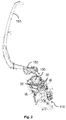
Fig. 1 illustrates an agricultural harvesting machine comprising a feed roll with a detection device according to the invention; -
Fig. 2 shows selected elements of the agricultural harvesting machine ofFigure 1 . -
Fig. 3 shows a sectional view according to the line III-III inFigure 2 , of a feed roll assembly comprising a detection device according to the invention; -
Fig. 4 shows an exploded view of the feed roll assembly ofFigure 3 ; -
Fig. 5 schematically illustrates the setup of the vibration sensor and the signal analysis by the control system of the detection device according to the invention; and -
Fig. 6 graphically shows the different steps of the signal analysis for a signal generated by the vibration sensor during which an impact of a foreign object occurs. -
Figure 1 and2 schematically show aforage harvester 1 comprising a detection device according to the invention. During a harvesting operation theforage harvester 1 travels along a direction V along a field and picks up crop, such as for example grass, by means of a pick-upmechanism 110. The crop is subsequently transported to a feeder which comprises a plurality of feeder rolls 32 which are driven to transport the crop at a controlled rate to thecutter drum 130 which cooperates with a fixed knife in order to chop the crop in pieces of a predetermined length. Subsequently the crop is propelled by means of afan element 150 towards aspout 160 for directing it into a suitable reservoir such as a cart pulled by a tractor for further transportation to a storage location. The detection device according to the invention is mounted into afeed roll assembly 30 which comprises afeed roll 32 of the feeder. For the forage harvester shown inFigure 1 , preferably the lowerfront feed roll 32 is chosen as this is the feed roll that is most likely to come into contact with a foreign object when crop material is being harvested. It is clear that the detection device could also be used in combination with alternative mechanisms for taking up crop. For example maize headers, grain headers, etc. could be attached to theforage harvester 1 and other types of harvesters such as for example combine harvesters, pull type forage harvesters, etc. -
Figure 3 shows a sectional view according to the line III-III inFigure 2 of the detection device for detection of a foreign object for anagricultural harvesting machine 1 in more detail. The detection device comprises thefeed roll assembly 30, which comprises acentral shaft 34. Around this central shaft 34 afeed roll 32 is rotatably mounted. According to the embodiment shown thefeed roll 32 is mounted to thecentral shaft 34 by means ofsuitable flanges 36 at both opposite sides of thefeed roll 32 which are connected tosuitable bearings 38 which rotatably connect these flanges to thecentral shaft 34. The rotational axes of thesebearings 38 are aligned and coincide with therotational axis 40 of thefeed roll 32. It is further clear that in this way the rotational axis of thefeed roll 32 is substantially parallel to the longitudinal axis of thecentral shaft 34. At least one of theseflanges 36 is provided withsuitable means 37 for coupling theflange 36 to a drive system, which when mounted into an agricultural vehicle can rotatably drive thefeed roll 32 around thecentral shaft 34, this central shaft then at both longitudinal ends being supported on the frame of theagricultural harvester 1 by means of suitable supports. It can further be seen that the detection device comprises at least onevibration sensor 20. In the embodiment shown inFigure 5 , threesuch vibration sensors 20 are mounted on thefeed roll assembly 30 such that it can sense vibrations induced into thefeed roll assembly 30, especially vibrations generated by impact of a foreign object, such as for example a stone, on thefeed roll assembly 30.Such vibration sensor 20 could for example be a piezoelectric vibration sensor or any other type of suitable directional vibration sensor. As can be seen thevibration sensors 20 are mounted on thecentral shaft 34. According to an alternative embodiment, thevibration sensors 20 could be mounted both on thefeed roll 32 and thecentral shaft 34. It is not required to mount a plurality ofvibration sensors 20, according to some embodiments asingle vibration sensor 20 could suffice. Thefeed roll 32 according to this embodiment is formed by a substantially cylindrical, metal plate, which is provided with longitudinal slats 33 in order to increase friction on the crop material. Thefeed roll 32 could be for example manufactured from stainless steel. Equally also the other elements of thefeed roll assembly 30 may be manufactured from a suitable metal such as stainless steel. - When a foreign object, such as for example a stone, impacts on the
feed roll 32 the impact force will cause vibrations into thefeed roll 32. Such a foreign object is normally transported along the direction of the crop flow and thus the most likely direction of the impact is along this crop flow direction which is substantially aligned with adirection 41 transverse to therotational axis 40 of thefeed roll 32. The impulse of the impact of the foreign object on thefeed roll 32 will result in a temporary deflection of the surface of thefeed roll 32 substantially along the direction of the impact force. This will then be the cause of structure borne vibrations in thefeed roll 32 and also in thecentral shaft 34 as the impact force and the resulting structure borne vibrations will also act on thecentral shaft 34 via theflanges 36 and thebearings 38. The amount of deflection of thefeed roll 32 or thecentral shaft 34 depends, amongst other things, on the stiffness of the structure, the direction of the impact force, the location of the impact force. It was found that the deflection of thefeed roll 32 or thecentral shaft 34 along thetransverse direction 41 is larger than that along the longitudinal direction which is substantially aligned with therotational axis 40. Therefor according to the invention thevibration sensors 20 are mounted such that they sense vibrations induced into thefeed roll assembly 30 in thedirection 41 transverse to therotational axis 40 of saidfeed roll 32. In this way the vibrations, which correspond to the largest deflections will result in the largest accelerations that are measured by thevibration sensor 20 in order to provide a clear signal for the detection of an impact. Although an impact will also generate longitudinal deflections in thefeed roll 32 and thecentral shaft 34, because of the larger longitudinal stiffness of these structures the amount of deflection generated will be lower, as will be the corresponding accelerations and vibrations detectable by avibration sensor 20. As schematically shown inFigure 5 the signal generated by thevibration sensors 20 is subsequently processed by acontrol system 50 which is coupled to thesevibration sensors 20. Thecontrol system 50 then analyses the signal generated by saidvibration sensor 20 in order to detect whether a foreign object has collided with saidfeed roller 32. Although prior art signal processing could be used in which for example the signal is compared to a threshold, optionally being pre-processed by suitable filtering, an improved configuration of the control system in order to process the signal more reliable in order to avoid false detections and faster in order to be able to intervene in the machine operation quick enough to avoid damage will be described further below. - As shown in
Figures 3 and4 thevibration sensor 20 is preferably mounted inside thefeed roll 32 so that it is shielded from for example moisture and dust generated by the harvesting process. Furthermore in this way thevibration sensor 20 is mounted close to the source of the vibrations generated by an impact of a foreign object on thefeed roll 32. The deflection along the transverse direction during the vibrations generated by an impact on thefeed roll 32 will become smaller for locations on thefeed roll assembly 30 closer to the supports for mounting saidfeed roll assembly 30 to saidharvesting machine 1 near the axial extremities of thecentral shaft 34. Therefore, according to the embodiment shown inFigures 2-5 , thevibration sensors 20 that are mounted on thecentral shaft 34 in between these supports, are preferably mounted in anaxial mounting zone 74 comprising thecenter 76 between these supports. Generally, this axial mountingzone 74 extends axially over a distance smaller than the distance between these two supports, however according to a specific embodiment it could be a relatively small zone around thecenter 76 between both supports where the transverse deflection of thefeeder roll 32 or the central shaft is likely to be sufficiently large for detection by avibration sensor 20. - As schematically shown in
Figure 5 and the corresponding signals inFigure 6 thecontrol system 50 in general is configured to analyze the signal generated by the one ormore vibration sensors 20 by sampling 54 this signal at a predetermined sample rate, calculating the square 56 of this sampled signal and subsequently integrating thesquared signal 56 or calculating thesum 58 of a predetermined number consecutive samples of said squared sampledsignal 56. The collision of the foreign object is then detected when the summed, squared sampledsignal 58 exceeds apredetermined threshold 65. As represented with thedetection signal 52 infigure 6 . According to a particularly simple embodiment this predetermined threshold could for example be a factory set parameter. When using the signal analysis described above, thedetection delay 59 between the impact occurring and the impact being detected is determined by the predetermined sample rate and the predetermined number of consecutive samples of which the squared value is summed. If for example the sample rate is 1 kHz and the predetermined number of samples of which the squared value is being summed is 10, then thedetection delay 59, which substantially corresponds to the quotient of said predetermined number of consecutive samples and said predetermined sample rate, will be about 10 / 1 kHz = 10ms. In this way the combination of the sample rate and this predetermined number of consecutive samples can be chosen in function of a predetermined maximum detection delay which still allows for timely intervention in the operation of the harvestingmachine 1 in order to avoid damage by a foreign object. - The impact of foreign objects generate acceleration signals as measured by the
vibration sensor 20 with as characteristics a main frequency component in the range of 80Hz to 200Hz, for example 120Hz. The acceleration signals are further largely sinusoidal in shape, which means that the vibrations manifest themselves at the location of thevibration sensor 20 as a sequence of acceleration phases immediately followed by similar deceleration phases in contrast to disturbance spikes which typically result in only a positive or negative specific deflection of the signal. As clearly shown inFigure 6 , squaring the sampled signal and subsequently summing a predetermined number of consecutive squared samples results in a clear discrimination of the signal generated by an impact of a foreign object versus a spike in the signal generated by a disturbance. Although it is possible to try out several combinations of sampling rate and predetermined number of consecutive samples in order to determine the ones that maximize the summed, squared sampledsignal 58 generated by the collision of the foreign object, choosing the predetermined number of samples can be performed in a simple way for a specific sampling rate if the main frequency component of the signal generated by the collision of a foreign object is known. For example as when the sampling rate is 1 kHz and the main frequency component is 120Hz, this predetermined number of samples can be chosen to be equal to about the main frequency component of said signal generated by said collision of said foreign object divided by said predetermined sampling rate, which is in this particular case 120Hz / 1kHz which results in about 9 samples. - In order to further enhance the reliability of the detection device according to an embodiment of the invention the
predetermined threshold 65 could be manually adjusted by an operator to be able to cope with varying harvesting conditions. Alternatively thecontrol system 50 could also be configured to receive an operating parameter of the harvestingmachine 1; such as for example the rotational speed of the feed roll, the type of crop being harvested, installed components on the harvesting machine, such as for example the type of header used, the number and type of knives installed on the cutter drum of a forage harvester, the cutting length for the crop when harvested by a forage harvester, harvesting conditions, etc. so that this predetermined threshold can be set to a value that allows the most reliable detection of a foreign object in the specific situation. - When a
vibration sensor 20 is mounted on thefeed roll 32 in addition to the vibration sensor(s) on theshaft 34, thisadditional vibration sensor 20 rotates together with thefeed roll 32. In such an embodiment thecontrol system 50 comprises two parts. A first part is also mounted on thefeed roll 32 and comprises a wireless transmitter configured to transmit a wireless signal generated on the basis of the signal generated by saidvibration sensor 20. In order to provide power to this wireless transmitter the first part of the controls system comprises a local power source. A second part of thecontrol system 50 is mounted on thecentral shaft 34 and comprises a wireless receiver configured to receive the wireless signal transmitted by the wireless transmitter. Multiple vibration sensors could be arranged on thefeed roll 32, which could be distributed along the longitudinal axis or around the cylindrical circumference of thefeed roll 32 in order to optimize detection of foreign object impacts along the entire circumference of the feed roll. Preferably thecontrol system 50 converts the analog signal from thevibration sensor 20 to a suitable digital signal before wireless transmission, so that the quality of the signal is not degraded by the wireless transmission and a reliable detection is possible. - In order to limit power consumption and prolong the operational life of the local power source, which could for example be a suitable battery, the
vibration sensor 20 is preferably a piezoelectric vibration sensor. Such piezoelectric vibration sensors, such as for example the known types of Bosch withreference number 0 261 231 196, are able to detect vibrations in the desired frequency range and are furthermore able to generate a signal without consuming power from a power source. In order to still further reduce power consumption from the local power source, the operation of the wireless transmitter may be optimized by only generating the wireless signal when the first part of thecontrol system 50 detects a collision of said foreign object. In order to do so the processing of thesignal 54 from thevibration sensor 20, this means, detecting when the summed, squaredsignal 58 exceeds thepredetermined threshold 65 in order to produce adetection signal 52 must be executed locally in the first part 62 of the control system. In order to still further extend the operating life of the local power source, it can comprise a rechargeable power source, such as for example a rechargeable battery. This rechargeable power source can then be recharged by means of an inductive power coupling between the first part and the second part of thecontrol system 50 as schematically illustrated. - Although the present invention has been illustrated by reference to specific embodiments, it will be apparent to those skilled in the art that the invention is not limited to the details of the foregoing illustrative embodiments, and that the present invention may be embodied with various changes and modifications without departing from the scope thereof. The present embodiments are therefore to be considered in all respects as illustrative and not restrictive, the scope of the invention being indicated by the appended claims rather than by the foregoing description, and all changes which come within the meaning and range of equivalency of the claims are therefore intended to be embraced therein. In other words, it is contemplated to cover any and all modifications, variations or equivalents that fall within the scope of the basic underlying principles and whose essential attributes are claimed in this patent application. It will furthermore be understood by the reader of this patent application that the words "comprising" or "comprise" do not exclude other elements or steps, that the words "a" or "an" do not exclude a plurality, and that a single element, such as a computer system, a processor, or another integrated unit may fulfil the functions of several means recited in the claims. Any reference signs in the claims shall not be construed as limiting the respective claims concerned. The terms "first", "second", third", "a", "b", "c", and the like, when used in the description or in the claims are introduced to distinguish between similar elements or steps and are not necessarily describing a sequential or chronological order. Similarly, the terms "top", "bottom", "over", "under", and the like are introduced for descriptive purposes and not necessarily to denote relative positions. It is to be understood that the terms so used are interchangeable under appropriate circumstances and embodiments of the invention are capable of operating according to the present invention in other sequences, or in orientations different from the one(s) described or illustrated above.
Claims (13)
- A detection device for detection of a foreign object in an agricultural harvesting machine (1),
the harvesting machine (1) comprising a feed roll assembly (30) with a central shaft (34) and a feed roll (32) rotatably mounted around the central shaft (34), the central shaft (34) and the feed roll (32) comprising a common rotational axis (40),
the detection device comprising:- at least one vibration sensor (20) being mounted on the central shaft (34) such that it can sense vibrations induced into the feed roll assembly (30); and- a control system (50) operatively coupled to the vibration sensor (20) and configured to:- analyze a signal generated by the vibration sensor (20); and- based on said analysis, detect whether the foreign object has collided with the feed roller (32),the vibration sensor (20) is mounted such that it senses vibrations induced into the feed roll assembly (30) in a direction (41) transverse to the common rotational axis (40).
CHARACTERIZED IN THAT - A detection device according to claim 1, characterized in that the central shaft (34) comprises near its axial extremities two supports for mounting the feed roll assembly (30) to the harvesting machine (1), and that
at least one vibration sensor (20) is mounted on the central shaft (34) in between the two supports. - A detection device according to claim 1 or 2, characterized in that the control system (50) is further configured to:- analyze the signal generated by the vibration sensor (20) by:- generating a sampled signal (54) by sampling the signal generated by the vibration sensor (20) at a predetermined sample rate;- calculating a squared sampled signal (56) as the square of the sampled signal (54);- calculating a summed, squared sampled signal (58) as the sum of a predetermined number of consecutive samples of the squared sampled signal; and- generate a detection signal (52) when the summed, squared sampled signal (58) exceeds a predetermined threshold (65) in order to detect a collision of the foreign object.
- A detection device according to claim 2, characterized in that the predetermined sample rate and the predetermined number of consecutive samples are related to a predetermined maximum delay for detection, in such a way that a quotient of the predetermined number of consecutive samples and the predetermined sample rate substantially corresponds to the predetermined maximum delay for detection.
- A detection device according to claim 2 or 3, characterized in that the sampling rate and the predetermined number of consecutive samples are determined such that a summed, squared sampled signal (58) generated by the collision of the foreign object is maximized.
- A detection device according to claim 5, characterized in that the predetermined number of consecutive samples is equal to about the main frequency component of the signal generated by the collision of the foreign object divided by the predetermined sampling rate.
- A detection device according to any of the claims 3 to 6, characterized in that the control system (50) is further configured to receive an operating parameter of the harvesting machine (1); and that the predetermined threshold (65) is determined in function of the operating parameter of the harvesting machine (1).
- A detection device according to claim 7, characterized in that the operating parameter of the harvesting machine (1) is one or more of the following:- rotational speed of the feed roll;- type of crop being harvested;- installed components on the harvesting machine, such as for example the type of header used, the number and type of knives installed on the cutter drum of a forage harvester; and/or- cutting length for the crop when harvested by a forage harvester.
- A detection device according to any of the preceding claims, characterized in that the detection device comprises:- at least one additional sensor (20) being mounted on the feed roll (32);- the control system (50) comprising a first part being mounted on the feed roll (32) and comprising:- a wireless transmitter configured to transmit a wireless signal generated by the control system (50) on the basis of the signal generated by the vibration sensor (20), and- a local power source for providing power to the wireless transmitter, and- the control system (50) further comprising a second part being mounted on the central shaft (34) comprising a wireless receiver configured to receive the wireless signal.
- A detection device according to claim 9, characterized in that the wireless signal is only generated when the control system (50) detects the collision of the foreign object.
- A detection device according to claim 9 or 10, characterized in that the local power source is a rechargeable power source and is configured to be recharged by means of a recharging means providing an inductive power coupling (70) between the first part and the second part of the control system (50).
- A detection device according to any of the preceding claims, wherein the vibration sensor (20) is a knock sensor.
- A method for detecting a foreign object with a detection device according to any of the preceding claims, characterized in that it comprises the steps of:- analyzing the signal generated by the vibration sensor (20) by:- determining a predetermined threshold (65);- generating a sampled signal (54) by sampling the signal generated by the vibration sensor (20) at a predetermined sample rate;- calculating a squared sampled signal (56) as the square of the sampled signal (54);- calculating a summed, squared sampled signal (58) as the sum of a predetermined number consecutive samples of the squared sampled signal; and- generating a detection signal (52) when the summed, squared sampled signal (58) exceeds the predetermined threshold (65) in order to detect a collision of the foreign object.
Applications Claiming Priority (1)
| Application Number | Priority Date | Filing Date | Title |
|---|---|---|---|
| BE2013/0035A BE1021124B1 (en) | 2013-01-18 | 2013-01-18 | DETECTION EQUIPMENT FOR DETECTING A STRANGE OBJECT FOR A HARVESTING MACHINE. |
Publications (3)
| Publication Number | Publication Date |
|---|---|
| EP2756748A1 true EP2756748A1 (en) | 2014-07-23 |
| EP2756748B1 EP2756748B1 (en) | 2015-08-19 |
| EP2756748B2 EP2756748B2 (en) | 2018-06-06 |
Family
ID=48092629
Family Applications (1)
| Application Number | Title | Priority Date | Filing Date |
|---|---|---|---|
| EP14151223.6A Active EP2756748B2 (en) | 2013-01-18 | 2014-01-15 | A detection device for detection of a foreign object for an agricultural harvesting machine |
Country Status (3)
| Country | Link |
|---|---|
| US (1) | US9668421B2 (en) |
| EP (1) | EP2756748B2 (en) |
| BE (1) | BE1021124B1 (en) |
Cited By (1)
| Publication number | Priority date | Publication date | Assignee | Title |
|---|---|---|---|---|
| EP3400763A1 (en) * | 2017-05-08 | 2018-11-14 | Aleksandar Cvetanovski | Device and method for controlling vibrations on an agricultural machine such as a mulching machine |
Families Citing this family (7)
| Publication number | Priority date | Publication date | Assignee | Title |
|---|---|---|---|---|
| DE102013201618A1 (en) * | 2013-01-31 | 2014-07-31 | Deere & Company | Vibration pick-up unit |
| US10271115B2 (en) * | 2015-04-08 | 2019-04-23 | Itt Manufacturing Enterprises Llc. | Nodal dynamic data acquisition and dissemination |
| PL234277B1 (en) * | 2017-01-27 | 2020-01-31 | Int Tobacco Machinery Poland Spolka Z Ograniczona Odpowiedzialnoscia | Tobacco industry cutting device and method for detecting defects of a cutting knife in the tobacco industry cutting device |
| US10820468B2 (en) * | 2018-09-19 | 2020-11-03 | Cnh Industrial America Llc | System and method for determining soil roughness of a field across which an agricultural implement is being moved based on ground engaging tool acceleration |
| NL2023209B1 (en) * | 2019-05-27 | 2020-12-02 | Ploeger Oxbo Europe B V | A device that is movable in a direction of travel over a land to be worked with the aid of the device, as well as a self-propelled agricultural machine |
| WO2022161748A1 (en) | 2021-01-27 | 2022-08-04 | Zf Cv Systems Global Gmbh | Operational safety of a agricultural implement |
| DE102024108699A1 (en) * | 2024-03-27 | 2025-10-02 | Claas Selbstfahrende Erntemaschinen Gmbh | Agricultural harvester |
Citations (6)
| Publication number | Priority date | Publication date | Assignee | Title |
|---|---|---|---|---|
| US3559805A (en) * | 1968-07-02 | 1971-02-02 | Patricia A Cragg | Stone and rock removing device |
| US4353199A (en) | 1981-04-15 | 1982-10-12 | Sperry Corporation | Stone detector for harvesting machines |
| US5092818A (en) | 1990-10-26 | 1992-03-03 | Ford New Holland, Inc. | Metal and hard object detectors with shared fixed support inside a feed roll |
| US20030115846A1 (en) | 2001-12-20 | 2003-06-26 | Duncan Wayne C. | Inertial system for detecting foreign objects between contra-rotating rolls |
| EP1731020A1 (en) * | 2005-06-10 | 2006-12-13 | CNH Belgium N.V. | Stone detection method and apparatus for a harvester |
| DE102008054488A1 (en) | 2008-12-10 | 2010-06-17 | Deere & Company, Moline | Device for detecting a foreign body that has entered a harvester |
Family Cites Families (18)
| Publication number | Priority date | Publication date | Assignee | Title |
|---|---|---|---|---|
| US4275546A (en) * | 1980-01-04 | 1981-06-30 | Sperry Corporation | Stone discriminator |
| US4464935A (en) * | 1983-05-09 | 1984-08-14 | General Electric Company | Shaft vibration evaluation |
| DE3577637D1 (en) | 1984-02-14 | 1990-06-21 | Nat Res Dev | DEVICE FOR RECEIVING AND PROMOTING HARVEST OR OTHER MATERIAL. |
| DD247117A3 (en) | 1985-10-04 | 1987-07-01 | Fortschritt Veb K | METHOD FOR RECOGNIZING FOREIGN BOOKS IN AGRICULTURAL HARVEST MACHINERY |
| US5078645A (en) | 1990-10-26 | 1992-01-07 | Ford New Holland, Inc. | Method and apparatus for hard object detection |
| DE19854562A1 (en) | 1998-11-26 | 2000-05-31 | Claas Saulgau Gmbh | Device for monitoring the feed assembly of an agricultural harvester |
| DE19904626C2 (en) | 1999-02-05 | 2001-05-17 | Case Harvesting Sys Gmbh | Process for the detection of foreign bodies in harvesting machines |
| DE10100521A1 (en) | 2001-01-08 | 2002-07-11 | Deere & Co | Monitoring device for a harvesting machine |
| US6601372B1 (en) * | 2002-02-22 | 2003-08-05 | New Holland North America, Inc. | Stone detection method and apparatus for harvester |
| DE102004035928A1 (en) | 2004-07-23 | 2006-03-16 | Claas Selbstfahrende Erntemaschinen Gmbh | Protection device for agricultural machines |
| US20060277883A1 (en) * | 2005-06-10 | 2006-12-14 | Berger John G | Acoustic stone detection for a feederhouse on an agricultural combine |
| DE102006033100B4 (en) † | 2005-07-14 | 2017-07-20 | Deere & Company | Device for detecting any foreign bodies picked up by a crop intake device |
| GB0604860D0 (en) * | 2006-03-10 | 2006-04-19 | Cnh Belgium Nv | Improvements in or relating to material stream sensors |
| DE102006015152A1 (en) * | 2006-03-30 | 2008-09-25 | Claas Selbstfahrende Erntemaschinen Gmbh | Borne sound sensor unit |
| GB2438578A (en) * | 2006-05-30 | 2007-12-05 | Cnh Belgium Nv | Metal object detection system for harvester |
| DE102009000351B4 (en) † | 2009-01-21 | 2011-05-19 | Deere & Company, Moline | Vibration pick-up unit |
| DE102011007843A1 (en) † | 2011-04-21 | 2012-10-25 | Deere & Company | Device for detecting a foreign body that has entered a harvester |
| DE102012109393A1 (en) * | 2012-10-02 | 2014-04-03 | Prüftechnik Dieter Busch AG | Apparatus and method for evaluating vibrations |
-
2013
- 2013-01-18 BE BE2013/0035A patent/BE1021124B1/en active
-
2014
- 2014-01-15 EP EP14151223.6A patent/EP2756748B2/en active Active
- 2014-01-16 US US14/157,223 patent/US9668421B2/en not_active Expired - Fee Related
Patent Citations (6)
| Publication number | Priority date | Publication date | Assignee | Title |
|---|---|---|---|---|
| US3559805A (en) * | 1968-07-02 | 1971-02-02 | Patricia A Cragg | Stone and rock removing device |
| US4353199A (en) | 1981-04-15 | 1982-10-12 | Sperry Corporation | Stone detector for harvesting machines |
| US5092818A (en) | 1990-10-26 | 1992-03-03 | Ford New Holland, Inc. | Metal and hard object detectors with shared fixed support inside a feed roll |
| US20030115846A1 (en) | 2001-12-20 | 2003-06-26 | Duncan Wayne C. | Inertial system for detecting foreign objects between contra-rotating rolls |
| EP1731020A1 (en) * | 2005-06-10 | 2006-12-13 | CNH Belgium N.V. | Stone detection method and apparatus for a harvester |
| DE102008054488A1 (en) | 2008-12-10 | 2010-06-17 | Deere & Company, Moline | Device for detecting a foreign body that has entered a harvester |
Cited By (1)
| Publication number | Priority date | Publication date | Assignee | Title |
|---|---|---|---|---|
| EP3400763A1 (en) * | 2017-05-08 | 2018-11-14 | Aleksandar Cvetanovski | Device and method for controlling vibrations on an agricultural machine such as a mulching machine |
Also Published As
| Publication number | Publication date |
|---|---|
| US20140202126A1 (en) | 2014-07-24 |
| EP2756748B2 (en) | 2018-06-06 |
| EP2756748B1 (en) | 2015-08-19 |
| BE1021124B1 (en) | 2016-01-11 |
| US9668421B2 (en) | 2017-06-06 |
Similar Documents
| Publication | Publication Date | Title |
|---|---|---|
| EP2756748B1 (en) | A detection device for detection of a foreign object for an agricultural harvesting machine | |
| US12604810B2 (en) | Systems, apparatus, and related methods for use with mergers | |
| US7415365B2 (en) | Structure-borne sound sensor unit | |
| CN107135735B (en) | Harvester and control system for harvester | |
| CN103975709B (en) | Agricultural cutter, especially field pulverizer | |
| US9125342B2 (en) | Method and device for the state detection of a cutting device | |
| US6886314B2 (en) | Device for measuring and/or checking the distance between a shear bar and a chopping knife | |
| US4353199A (en) | Stone detector for harvesting machines | |
| US5083976A (en) | Adjustment of a shear bar using an air-borne sound detector | |
| CN110996652B (en) | Harvesting operation area determination device | |
| BE1019497A5 (en) | DEVICE FOR DISTINGUISHING A FOREIGN BODY HAVING PENETRATING IN A HARVESTING MACHINE. | |
| US11566883B2 (en) | Cutting sharpness detection device | |
| EP3135101B1 (en) | Monitoring system for an agricultural harvester and agricultural harvester | |
| EP4088559B1 (en) | Grain loss sensing | |
| EP4088560B1 (en) | Grain loss sensing | |
| EP4144202B1 (en) | Active loss monitor for a harvester | |
| EP4104662A1 (en) | Cutting apparatus | |
| US5092818A (en) | Metal and hard object detectors with shared fixed support inside a feed roll | |
| US10462967B2 (en) | Measuring device for measuring a mass flow composed of bulk material | |
| US4720963A (en) | Method of detecting stones in the intake of a field chopper | |
| US20060277883A1 (en) | Acoustic stone detection for a feederhouse on an agricultural combine | |
| EA023115B1 (en) | Device for detecting foreign body in harvesting machine | |
| US5070682A (en) | Acoustic detector with start-up control | |
| US7523599B2 (en) | Method and device for adjusting the sensitivity of a foreign-object detection device | |
| US5078645A (en) | Method and apparatus for hard object detection |
Legal Events
| Date | Code | Title | Description |
|---|---|---|---|
| PUAI | Public reference made under article 153(3) epc to a published international application that has entered the european phase |
Free format text: ORIGINAL CODE: 0009012 |
|
| 17P | Request for examination filed |
Effective date: 20140115 |
|
| AK | Designated contracting states |
Kind code of ref document: A1 Designated state(s): AL AT BE BG CH CY CZ DE DK EE ES FI FR GB GR HR HU IE IS IT LI LT LU LV MC MK MT NL NO PL PT RO RS SE SI SK SM TR |
|
| AX | Request for extension of the european patent |
Extension state: BA ME |
|
| R17P | Request for examination filed (corrected) |
Effective date: 20150123 |
|
| RBV | Designated contracting states (corrected) |
Designated state(s): AL AT BE BG CH CY CZ DE DK EE ES FI FR GB GR HR HU IE IS IT LI LT LU LV MC MK MT NL NO PL PT RO RS SE SI SK SM TR |
|
| GRAP | Despatch of communication of intention to grant a patent |
Free format text: ORIGINAL CODE: EPIDOSNIGR1 |
|
| RIC1 | Information provided on ipc code assigned before grant |
Ipc: A01D 75/18 20060101AFI20150227BHEP |
|
| INTG | Intention to grant announced |
Effective date: 20150318 |
|
| GRAS | Grant fee paid |
Free format text: ORIGINAL CODE: EPIDOSNIGR3 |
|
| GRAA | (expected) grant |
Free format text: ORIGINAL CODE: 0009210 |
|
| AK | Designated contracting states |
Kind code of ref document: B1 Designated state(s): AL AT BE BG CH CY CZ DE DK EE ES FI FR GB GR HR HU IE IS IT LI LT LU LV MC MK MT NL NO PL PT RO RS SE SI SK SM TR |
|
| REG | Reference to a national code |
Ref country code: GB Ref legal event code: FG4D |
|
| REG | Reference to a national code |
Ref country code: CH Ref legal event code: EP |
|
| REG | Reference to a national code |
Ref country code: IE Ref legal event code: FG4D |
|
| REG | Reference to a national code |
Ref country code: AT Ref legal event code: REF Ref document number: 743118 Country of ref document: AT Kind code of ref document: T Effective date: 20150915 |
|
| REG | Reference to a national code |
Ref country code: DE Ref legal event code: R096 Ref document number: 602014000140 Country of ref document: DE |
|
| REG | Reference to a national code |
Ref country code: FR Ref legal event code: PLFP Year of fee payment: 3 |
|
| REG | Reference to a national code |
Ref country code: AT Ref legal event code: MK05 Ref document number: 743118 Country of ref document: AT Kind code of ref document: T Effective date: 20150819 |
|
| REG | Reference to a national code |
Ref country code: LT Ref legal event code: MG4D |
|
| REG | Reference to a national code |
Ref country code: NL Ref legal event code: MP Effective date: 20150819 |
|
| PG25 | Lapsed in a contracting state [announced via postgrant information from national office to epo] |
Ref country code: LV Free format text: LAPSE BECAUSE OF FAILURE TO SUBMIT A TRANSLATION OF THE DESCRIPTION OR TO PAY THE FEE WITHIN THE PRESCRIBED TIME-LIMIT Effective date: 20150819 Ref country code: LT Free format text: LAPSE BECAUSE OF FAILURE TO SUBMIT A TRANSLATION OF THE DESCRIPTION OR TO PAY THE FEE WITHIN THE PRESCRIBED TIME-LIMIT Effective date: 20150819 Ref country code: FI Free format text: LAPSE BECAUSE OF FAILURE TO SUBMIT A TRANSLATION OF THE DESCRIPTION OR TO PAY THE FEE WITHIN THE PRESCRIBED TIME-LIMIT Effective date: 20150819 Ref country code: NO Free format text: LAPSE BECAUSE OF FAILURE TO SUBMIT A TRANSLATION OF THE DESCRIPTION OR TO PAY THE FEE WITHIN THE PRESCRIBED TIME-LIMIT Effective date: 20151119 Ref country code: GR Free format text: LAPSE BECAUSE OF FAILURE TO SUBMIT A TRANSLATION OF THE DESCRIPTION OR TO PAY THE FEE WITHIN THE PRESCRIBED TIME-LIMIT Effective date: 20151120 |
|
| PG25 | Lapsed in a contracting state [announced via postgrant information from national office to epo] |
Ref country code: IS Free format text: LAPSE BECAUSE OF FAILURE TO SUBMIT A TRANSLATION OF THE DESCRIPTION OR TO PAY THE FEE WITHIN THE PRESCRIBED TIME-LIMIT Effective date: 20151219 Ref country code: ES Free format text: LAPSE BECAUSE OF FAILURE TO SUBMIT A TRANSLATION OF THE DESCRIPTION OR TO PAY THE FEE WITHIN THE PRESCRIBED TIME-LIMIT Effective date: 20150819 Ref country code: SE Free format text: LAPSE BECAUSE OF FAILURE TO SUBMIT A TRANSLATION OF THE DESCRIPTION OR TO PAY THE FEE WITHIN THE PRESCRIBED TIME-LIMIT Effective date: 20150819 Ref country code: PT Free format text: LAPSE BECAUSE OF FAILURE TO SUBMIT A TRANSLATION OF THE DESCRIPTION OR TO PAY THE FEE WITHIN THE PRESCRIBED TIME-LIMIT Effective date: 20151221 Ref country code: AT Free format text: LAPSE BECAUSE OF FAILURE TO SUBMIT A TRANSLATION OF THE DESCRIPTION OR TO PAY THE FEE WITHIN THE PRESCRIBED TIME-LIMIT Effective date: 20150819 Ref country code: PL Free format text: LAPSE BECAUSE OF FAILURE TO SUBMIT A TRANSLATION OF THE DESCRIPTION OR TO PAY THE FEE WITHIN THE PRESCRIBED TIME-LIMIT Effective date: 20150819 Ref country code: RS Free format text: LAPSE BECAUSE OF FAILURE TO SUBMIT A TRANSLATION OF THE DESCRIPTION OR TO PAY THE FEE WITHIN THE PRESCRIBED TIME-LIMIT Effective date: 20150819 |
|
| PG25 | Lapsed in a contracting state [announced via postgrant information from national office to epo] |
Ref country code: NL Free format text: LAPSE BECAUSE OF FAILURE TO SUBMIT A TRANSLATION OF THE DESCRIPTION OR TO PAY THE FEE WITHIN THE PRESCRIBED TIME-LIMIT Effective date: 20150819 |
|
| PG25 | Lapsed in a contracting state [announced via postgrant information from national office to epo] |
Ref country code: EE Free format text: LAPSE BECAUSE OF FAILURE TO SUBMIT A TRANSLATION OF THE DESCRIPTION OR TO PAY THE FEE WITHIN THE PRESCRIBED TIME-LIMIT Effective date: 20150819 Ref country code: SK Free format text: LAPSE BECAUSE OF FAILURE TO SUBMIT A TRANSLATION OF THE DESCRIPTION OR TO PAY THE FEE WITHIN THE PRESCRIBED TIME-LIMIT Effective date: 20150819 Ref country code: DK Free format text: LAPSE BECAUSE OF FAILURE TO SUBMIT A TRANSLATION OF THE DESCRIPTION OR TO PAY THE FEE WITHIN THE PRESCRIBED TIME-LIMIT Effective date: 20150819 Ref country code: CZ Free format text: LAPSE BECAUSE OF FAILURE TO SUBMIT A TRANSLATION OF THE DESCRIPTION OR TO PAY THE FEE WITHIN THE PRESCRIBED TIME-LIMIT Effective date: 20150819 |
|
| REG | Reference to a national code |
Ref country code: DE Ref legal event code: R026 Ref document number: 602014000140 Country of ref document: DE |
|
| PLBI | Opposition filed |
Free format text: ORIGINAL CODE: 0009260 |
|
| PG25 | Lapsed in a contracting state [announced via postgrant information from national office to epo] |
Ref country code: RO Free format text: LAPSE BECAUSE OF FAILURE TO SUBMIT A TRANSLATION OF THE DESCRIPTION OR TO PAY THE FEE WITHIN THE PRESCRIBED TIME-LIMIT Effective date: 20150819 |
|
| 26 | Opposition filed |
Opponent name: DEERE & COMPANY/JOHN DEERE GMBH & CO. KG Effective date: 20160518 |
|
| PLAX | Notice of opposition and request to file observation + time limit sent |
Free format text: ORIGINAL CODE: EPIDOSNOBS2 |
|
| PG25 | Lapsed in a contracting state [announced via postgrant information from national office to epo] |
Ref country code: LU Free format text: LAPSE BECAUSE OF FAILURE TO SUBMIT A TRANSLATION OF THE DESCRIPTION OR TO PAY THE FEE WITHIN THE PRESCRIBED TIME-LIMIT Effective date: 20160115 Ref country code: SI Free format text: LAPSE BECAUSE OF FAILURE TO SUBMIT A TRANSLATION OF THE DESCRIPTION OR TO PAY THE FEE WITHIN THE PRESCRIBED TIME-LIMIT Effective date: 20150819 |
|
| PG25 | Lapsed in a contracting state [announced via postgrant information from national office to epo] |
Ref country code: MC Free format text: LAPSE BECAUSE OF FAILURE TO SUBMIT A TRANSLATION OF THE DESCRIPTION OR TO PAY THE FEE WITHIN THE PRESCRIBED TIME-LIMIT Effective date: 20150819 |
|
| REG | Reference to a national code |
Ref country code: IE Ref legal event code: MM4A |
|
| PLBB | Reply of patent proprietor to notice(s) of opposition received |
Free format text: ORIGINAL CODE: EPIDOSNOBS3 |
|
| REG | Reference to a national code |
Ref country code: FR Ref legal event code: PLFP Year of fee payment: 4 |
|
| PG25 | Lapsed in a contracting state [announced via postgrant information from national office to epo] |
Ref country code: IE Free format text: LAPSE BECAUSE OF NON-PAYMENT OF DUE FEES Effective date: 20160115 |
|
| PG25 | Lapsed in a contracting state [announced via postgrant information from national office to epo] |
Ref country code: MT Free format text: LAPSE BECAUSE OF FAILURE TO SUBMIT A TRANSLATION OF THE DESCRIPTION OR TO PAY THE FEE WITHIN THE PRESCRIBED TIME-LIMIT Effective date: 20150819 |
|
| REG | Reference to a national code |
Ref country code: CH Ref legal event code: PL |
|
| PG25 | Lapsed in a contracting state [announced via postgrant information from national office to epo] |
Ref country code: CH Free format text: LAPSE BECAUSE OF NON-PAYMENT OF DUE FEES Effective date: 20170131 Ref country code: LI Free format text: LAPSE BECAUSE OF NON-PAYMENT OF DUE FEES Effective date: 20170131 |
|
| REG | Reference to a national code |
Ref country code: FR Ref legal event code: PLFP Year of fee payment: 5 |
|
| PUAH | Patent maintained in amended form |
Free format text: ORIGINAL CODE: 0009272 |
|
| STAA | Information on the status of an ep patent application or granted ep patent |
Free format text: STATUS: PATENT MAINTAINED AS AMENDED |
|
| PG25 | Lapsed in a contracting state [announced via postgrant information from national office to epo] |
Ref country code: CY Free format text: LAPSE BECAUSE OF FAILURE TO SUBMIT A TRANSLATION OF THE DESCRIPTION OR TO PAY THE FEE WITHIN THE PRESCRIBED TIME-LIMIT Effective date: 20150819 Ref country code: SM Free format text: LAPSE BECAUSE OF FAILURE TO SUBMIT A TRANSLATION OF THE DESCRIPTION OR TO PAY THE FEE WITHIN THE PRESCRIBED TIME-LIMIT Effective date: 20150819 Ref country code: HU Free format text: LAPSE BECAUSE OF FAILURE TO SUBMIT A TRANSLATION OF THE DESCRIPTION OR TO PAY THE FEE WITHIN THE PRESCRIBED TIME-LIMIT; INVALID AB INITIO Effective date: 20140115 |
|
| 27A | Patent maintained in amended form |
Effective date: 20180606 |
|
| AK | Designated contracting states |
Kind code of ref document: B2 Designated state(s): AL AT BE BG CH CY CZ DE DK EE ES FI FR GB GR HR HU IE IS IT LI LT LU LV MC MK MT NL NO PL PT RO RS SE SI SK SM TR |
|
| REG | Reference to a national code |
Ref country code: DE Ref legal event code: R102 Ref document number: 602014000140 Country of ref document: DE |
|
| PG25 | Lapsed in a contracting state [announced via postgrant information from national office to epo] |
Ref country code: TR Free format text: LAPSE BECAUSE OF FAILURE TO SUBMIT A TRANSLATION OF THE DESCRIPTION OR TO PAY THE FEE WITHIN THE PRESCRIBED TIME-LIMIT Effective date: 20150819 Ref country code: MT Free format text: LAPSE BECAUSE OF FAILURE TO SUBMIT A TRANSLATION OF THE DESCRIPTION OR TO PAY THE FEE WITHIN THE PRESCRIBED TIME-LIMIT Effective date: 20160131 Ref country code: MK Free format text: LAPSE BECAUSE OF FAILURE TO SUBMIT A TRANSLATION OF THE DESCRIPTION OR TO PAY THE FEE WITHIN THE PRESCRIBED TIME-LIMIT Effective date: 20150819 Ref country code: HR Free format text: LAPSE BECAUSE OF FAILURE TO SUBMIT A TRANSLATION OF THE DESCRIPTION OR TO PAY THE FEE WITHIN THE PRESCRIBED TIME-LIMIT Effective date: 20150819 |
|
| PG25 | Lapsed in a contracting state [announced via postgrant information from national office to epo] |
Ref country code: BG Free format text: LAPSE BECAUSE OF FAILURE TO SUBMIT A TRANSLATION OF THE DESCRIPTION OR TO PAY THE FEE WITHIN THE PRESCRIBED TIME-LIMIT Effective date: 20150819 |
|
| REG | Reference to a national code |
Ref country code: BE Ref legal event code: FP Effective date: 20150907 |
|
| PG25 | Lapsed in a contracting state [announced via postgrant information from national office to epo] |
Ref country code: AL Free format text: LAPSE BECAUSE OF FAILURE TO SUBMIT A TRANSLATION OF THE DESCRIPTION OR TO PAY THE FEE WITHIN THE PRESCRIBED TIME-LIMIT Effective date: 20150819 |
|
| REG | Reference to a national code |
Ref country code: DE Ref legal event code: R082 Ref document number: 602014000140 Country of ref document: DE Representative=s name: MEISSNER BOLTE PATENTANWAELTE RECHTSANWAELTE P, DE |
|
| PGFP | Annual fee paid to national office [announced via postgrant information from national office to epo] |
Ref country code: BE Payment date: 20240124 Year of fee payment: 11 |
|
| PG25 | Lapsed in a contracting state [announced via postgrant information from national office to epo] |
Ref country code: BE Free format text: LAPSE BECAUSE OF NON-PAYMENT OF DUE FEES Effective date: 20250131 |
|
| REG | Reference to a national code |
Ref country code: BE Ref legal event code: MM Effective date: 20250131 |
|
| PGFP | Annual fee paid to national office [announced via postgrant information from national office to epo] |
Ref country code: GB Payment date: 20260126 Year of fee payment: 13 |
|
| PGFP | Annual fee paid to national office [announced via postgrant information from national office to epo] |
Ref country code: DE Payment date: 20260127 Year of fee payment: 13 |
|
| PGFP | Annual fee paid to national office [announced via postgrant information from national office to epo] |
Ref country code: IT Payment date: 20260123 Year of fee payment: 13 |
|
| PGFP | Annual fee paid to national office [announced via postgrant information from national office to epo] |
Ref country code: FR Payment date: 20260126 Year of fee payment: 13 |