EP2756735B1 - Lighting device - Google Patents
Lighting device Download PDFInfo
- Publication number
- EP2756735B1 EP2756735B1 EP12753095.4A EP12753095A EP2756735B1 EP 2756735 B1 EP2756735 B1 EP 2756735B1 EP 12753095 A EP12753095 A EP 12753095A EP 2756735 B1 EP2756735 B1 EP 2756735B1
- Authority
- EP
- European Patent Office
- Prior art keywords
- wireless communication
- tube
- lighting device
- communication circuit
- antenna
- Prior art date
- Legal status (The legal status is an assumption and is not a legal conclusion. Google has not performed a legal analysis and makes no representation as to the accuracy of the status listed.)
- Active
Links
Images
Classifications
-
- F—MECHANICAL ENGINEERING; LIGHTING; HEATING; WEAPONS; BLASTING
- F21—LIGHTING
- F21V—FUNCTIONAL FEATURES OR DETAILS OF LIGHTING DEVICES OR SYSTEMS THEREOF; STRUCTURAL COMBINATIONS OF LIGHTING DEVICES WITH OTHER ARTICLES, NOT OTHERWISE PROVIDED FOR
- F21V23/00—Arrangement of electric circuit elements in or on lighting devices
- F21V23/003—Arrangement of electric circuit elements in or on lighting devices the elements being electronics drivers or controllers for operating the light source, e.g. for a LED array
- F21V23/004—Arrangement of electric circuit elements in or on lighting devices the elements being electronics drivers or controllers for operating the light source, e.g. for a LED array arranged on a substrate, e.g. a printed circuit board
- F21V23/006—Arrangement of electric circuit elements in or on lighting devices the elements being electronics drivers or controllers for operating the light source, e.g. for a LED array arranged on a substrate, e.g. a printed circuit board the substrate being distinct from the light source holder
-
- F—MECHANICAL ENGINEERING; LIGHTING; HEATING; WEAPONS; BLASTING
- F21—LIGHTING
- F21K—NON-ELECTRIC LIGHT SOURCES USING LUMINESCENCE; LIGHT SOURCES USING ELECTROCHEMILUMINESCENCE; LIGHT SOURCES USING CHARGES OF COMBUSTIBLE MATERIAL; LIGHT SOURCES USING SEMICONDUCTOR DEVICES AS LIGHT-GENERATING ELEMENTS; LIGHT SOURCES NOT OTHERWISE PROVIDED FOR
- F21K9/00—Light sources using semiconductor devices as light-generating elements, e.g. using light-emitting diodes [LED] or lasers
-
- F—MECHANICAL ENGINEERING; LIGHTING; HEATING; WEAPONS; BLASTING
- F21—LIGHTING
- F21V—FUNCTIONAL FEATURES OR DETAILS OF LIGHTING DEVICES OR SYSTEMS THEREOF; STRUCTURAL COMBINATIONS OF LIGHTING DEVICES WITH OTHER ARTICLES, NOT OTHERWISE PROVIDED FOR
- F21V29/00—Protecting lighting devices from thermal damage; Cooling or heating arrangements specially adapted for lighting devices or systems
- F21V29/50—Cooling arrangements
- F21V29/70—Cooling arrangements characterised by passive heat-dissipating elements, e.g. heat-sinks
-
- H—ELECTRICITY
- H05—ELECTRIC TECHNIQUES NOT OTHERWISE PROVIDED FOR
- H05B—ELECTRIC HEATING; ELECTRIC LIGHT SOURCES NOT OTHERWISE PROVIDED FOR; CIRCUIT ARRANGEMENTS FOR ELECTRIC LIGHT SOURCES, IN GENERAL
- H05B45/00—Circuit arrangements for operating light-emitting diodes [LED]
- H05B45/10—Controlling the intensity of the light
-
- H—ELECTRICITY
- H05—ELECTRIC TECHNIQUES NOT OTHERWISE PROVIDED FOR
- H05B—ELECTRIC HEATING; ELECTRIC LIGHT SOURCES NOT OTHERWISE PROVIDED FOR; CIRCUIT ARRANGEMENTS FOR ELECTRIC LIGHT SOURCES, IN GENERAL
- H05B47/00—Circuit arrangements for operating light sources in general, i.e. where the type of light source is not relevant
- H05B47/10—Controlling the light source
- H05B47/175—Controlling the light source by remote control
- H05B47/19—Controlling the light source by remote control via wireless transmission
-
- F—MECHANICAL ENGINEERING; LIGHTING; HEATING; WEAPONS; BLASTING
- F21—LIGHTING
- F21Y—INDEXING SCHEME ASSOCIATED WITH SUBCLASSES F21K, F21L, F21S and F21V, RELATING TO THE FORM OR THE KIND OF THE LIGHT SOURCES OR OF THE COLOUR OF THE LIGHT EMITTED
- F21Y2115/00—Light-generating elements of semiconductor light sources
- F21Y2115/10—Light-emitting diodes [LED]
Definitions
- the present invention relates to a lighting device.
- the illuminating devices are widely used for illumination, and higher requirements are put on the illuminating devices, for instance, the lamp is required to be capable of being turned on and off automatically and periodically, or capable of providing brightness to different degrees in different application scenes. In particular, it is required to wirelessly control the light to facilitate a remote and short-range operation. Accordingly, in various lighting devices, a wireless circuit and an antenna are especially arranged in a tube light for using a wireless communication protocol and an exterior light control center or a wireless controller to conduct communication so as to receive an instruction.
- a wireless circuit since a metal general shields a wireless signal, a wireless circuit, especially an antenna, cannot be mounted at the place where metal shielding is present.
- the wireless circuit and antenna are generally placed on a light engine for the reason that a heat sink is made of metal and the cover is made of plastic, such that a wireless signal may pass through the cover.
- a disadvantage to do so.
- some LEDs need to be removed from the light engine in order to mount the wireless circuit and the antenna on the light engine, whereby the wireless circuit is mounted on the position where the LEDs are removed. That is to say, the wireless circuit and the LEDs are arranged side by side on the light engine. Even if the wireless circuit and the antenna do not occupy a lot of space, the tube light still has a dark part, which affects significantly its performance and user's comments thereon.
- US2010271802 A1 is directed generally to devices and applications related to the use of wireless control and wireless power in light emitting diode (LED) based lighting devices. More particularly, the devices and applications according to various embodiments of the present invention make use of wireless control and wireless power in lighting devices to provide advantages in ease of installation, in the ability to install lighting in locations independent of a connection to wired power, in cost savings, in energy efficiency and in the reduction of energy consumption at times of peak demand through controls and power management and in safety, security, and convenience for the end user.
- LED light emitting diode
- the object of the present invention lies in providing a novel lighting device. Said device can overcome the defects present in the prior art, maintains the profile of a conventional lighting device, is easy to mount, is capable of conducting a good wireless communication, and has a higher brightness.
- the object of the present invention is realized by a lighting device, comprising a tube and end caps located at two ends of the tube, a lighting assembly arranged in the tube, and a driver for the lighting assembly, characterized by, further comprising an antenna and a wireless communication circuit for conducting wireless communication, the antenna being provided in the end cap and the wireless communication circuit being provided in the tube or at least partially provided in the end cap, and one side of the wire communication circuit being connected to the driver and the other side thereof being connected to the antenna. Since the antenna for wireless communication is provided advantageously in the end cap, the space on light engine inside the tube is not occupied as compared with the prior art.
- the wireless communication circuit may be provided in the tube or partially in the end cap for electrically connecting the antenna in the cap end and the driver inside the tube, which ensures that a wireless signal is received using the antenna and transmitted to the driver via the wireless communication circuit, and the lighting assembly is driven by the driver to operate normally.
- the manner of connecting via the circuit board in the prior art is replaced for controlling directly the working states of the LED driver via the wireless communication circuit. Therefore, more light sources especially LEDs may be arranged on the circuit board, such that the overall brightness of the lighting device is unaffected while realizing a good wireless communication.
- the wireless communication circuit is formed on a wireless communication circuit board, and the antenna is connected to the wireless communication circuit board, thereby realizing an effective signal transmission between the antenna and the wireless communication circuit board.
- the LED driver and the wireless communication circuit board are arranged side by side and connected in series.
- Such a connection manner facilitates assembling, ensures the effect of communication between the LED driver and the wireless communication circuit, and reduces as much as possible communication interruption due to the wire connection.
- the lighting assembly comprises a circuit board and a plurality of LEDs arranged on and at one side of the circuit board.
- the LED light source can be provided for realizing energy-efficient illumination.
- a heat sink is included, wherein the heat sink is provided on one side of the circuit board facing away from the LED and the LED driver is provided on one side of the heat sink facing away from the circuit board.
- the heat sink is arranged between the LED driver and the light engine, which not only allows the two to be supported by the heat sink but also enables sufficient use of a limited space so as to mount enough LEDs on the light engine for improving illumination.
- the tube comprises an upper housing and a lower housing mounted together and the upper housing or the lower housing of the housing is designed as a part of the heat sink.
- the heat dissipating effect is further improved.
- the end caps are made of plastic, which ensures that the wireless communication signal is not subject to shielding, may reduce manufacturing cost and reduces the weight of the lighting device.
- Other suitable light-weight materials reducing or eliminating shield may also be taken into consideration for making an end cap.
- a lighting device which maintains the profile of a conventional tube lighting devices, is capable of conducting a good wireless communication, is easy to mount, and has a higher brightness.
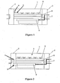
- Fig. 1 is a schematic diagram of an internal structure of a tube-shaped lighting device according to the prior art.
- End caps 2 are located at two ends of a tube 1, respectively, and in the end caps 2 there are large unoccupied structural spaces.
- a light engine 8, a heat sink 7, and an LED driver 6 are disposed laminatingly layer by layer inside the tube 1.
- a plurality of LEDs 9 for illumination are provided on the light engine 8.
- an antenna 4 and a wireless communication circuit 5 for conducting a wireless communication are located on the light engine 8, such that the position where the LEDs are initially arranged is occupied and the brightness of the lighting device is affected.
- Fig. 2 is a schematic diagram of an internal structure of a lighting device according to a specific embodiment of the present invention, wherein the lighting device is designed as a tube shape. It is shown by comparison with Fig. 1 that, in a lighting device also having a tube-shape structure, the antenna 4 for receiving a wireless signal is located in the cap end 2 on one side of the tube 1, the wireless communication circuit 5, designed in the form of a wireless communication circuit board, is partially located in the end cap 2 and partially in the tube 1 for connecting the antenna 4 to the LED driver 6 inside the tube 1 so as to control the lighting device.
- the wireless communication circuit board and the LED driver 6 are arranged side by side and connected together. The two are connected directly, whereby assembling may be performed simply, the communication between the LED driver 6 and the wireless communication circuit 5 may be ensured, and communication interruption caused by wire connection or a short circuit due to an unreasonable wire connection may be reduced as much as possible.
- the end caps 2 which are optionally made of a light-weight material such as plastic which not shields a wireless signal and the tube 1 may be connected together, whereby respective components of the end caps 2 and the tube 1 may be assembled conveniently.
- the light engine 8, the heat sink 7, and the LED driver 6 are disposed stacked inside the tube 1. Since there is no need to arrange the antenna 4 and the wireless communication circuit 5 inside the tube 1, a plurality of LEDs may be placed over the whole space of the light engine 8 so as to provide sufficient brightness.
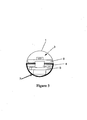
- Fig. 3 is a cross-sectional schematic diagram of an end plane of a lighting device according to another embodiment of the present invention.
- the heat sink 7 designed as a part of the tube 1 has a semicylindrical structure.
- the antenna 4 and the wireless communication circuit 5 with one side connected thereto may be wholly placed in the end cap 2.
- the wireless communication circuit 5 may be placed partially in the end cap 2 to allow for a more compact design of the lighting device.
- the other side of the wireless communication circuit 5 is connected to the LED driver 6 inside the tube 1.
- the LED driver 6 Since the wireless communication circuit 5 and the LED driver 6 are arranged side by side, the LED driver 6 is not shown in the cross-sectional view of said end plane.
- the elongated mounting plane of the heat sink 7 goes longitudinally through the whole tube 1 and is located near the center of the tube 1.
- the LED driver 6 is fixed at one side where the mounting plane faces the arch-shaped structure of the heat sink 7, and the light engine 8 having a plurality of LEDs 9 are fixed to the other side of the mounting plane.
Landscapes
- Engineering & Computer Science (AREA)
- General Engineering & Computer Science (AREA)
- Microelectronics & Electronic Packaging (AREA)
- Physics & Mathematics (AREA)
- Optics & Photonics (AREA)
- Computer Networks & Wireless Communication (AREA)
- Arrangement Of Elements, Cooling, Sealing, Or The Like Of Lighting Devices (AREA)
- Non-Portable Lighting Devices Or Systems Thereof (AREA)
- Support Of Aerials (AREA)
- Details Of Aerials (AREA)
Description
- The present invention relates to a lighting device.
- In modern society, the illuminating devices are widely used for illumination, and higher requirements are put on the illuminating devices, for instance, the lamp is required to be capable of being turned on and off automatically and periodically, or capable of providing brightness to different degrees in different application scenes. In particular, it is required to wirelessly control the light to facilitate a remote and short-range operation. Accordingly, in various lighting devices, a wireless circuit and an antenna are especially arranged in a tube light for using a wireless communication protocol and an exterior light control center or a wireless controller to conduct communication so as to receive an instruction.
- In the prior art, since a metal general shields a wireless signal, a wireless circuit, especially an antenna, cannot be mounted at the place where metal shielding is present. The wireless circuit and antenna are generally placed on a light engine for the reason that a heat sink is made of metal and the cover is made of plastic, such that a wireless signal may pass through the cover. However, it is obvious that there is a disadvantage to do so. With a plurality of LEDs provided above a light engine, some LEDs need to be removed from the light engine in order to mount the wireless circuit and the antenna on the light engine, whereby the wireless circuit is mounted on the position where the LEDs are removed. That is to say, the wireless circuit and the LEDs are arranged side by side on the light engine. Even if the wireless circuit and the antenna do not occupy a lot of space, the tube light still has a dark part, which affects significantly its performance and user's comments thereon.
-
US2010271802 A1 is directed generally to devices and applications related to the use of wireless control and wireless power in light emitting diode (LED) based lighting devices. More particularly, the devices and applications according to various embodiments of the present invention make use of wireless control and wireless power in lighting devices to provide advantages in ease of installation, in the ability to install lighting in locations independent of a connection to wired power, in cost savings, in energy efficiency and in the reduction of energy consumption at times of peak demand through controls and power management and in safety, security, and convenience for the end user. - The object of the present invention lies in providing a novel lighting device. Said device can overcome the defects present in the prior art, maintains the profile of a conventional lighting device, is easy to mount, is capable of conducting a good wireless communication, and has a higher brightness.
- The object of the present invention is realized by a lighting device, comprising a tube and end caps located at two ends of the tube, a lighting assembly arranged in the tube, and a driver for the lighting assembly, characterized by, further comprising an antenna and a wireless communication circuit for conducting wireless communication, the antenna being provided in the end cap and the wireless communication circuit being provided in the tube or at least partially provided in the end cap, and one side of the wire communication circuit being connected to the driver and the other side thereof being connected to the antenna. Since the antenna for wireless communication is provided advantageously in the end cap, the space on light engine inside the tube is not occupied as compared with the prior art. In addition, the wireless communication circuit may be provided in the tube or partially in the end cap for electrically connecting the antenna in the cap end and the driver inside the tube, which ensures that a wireless signal is received using the antenna and transmitted to the driver via the wireless communication circuit, and the lighting assembly is driven by the driver to operate normally. Thus, the manner of connecting via the circuit board in the prior art is replaced for controlling directly the working states of the LED driver via the wireless communication circuit. Therefore, more light sources especially LEDs may be arranged on the circuit board, such that the overall brightness of the lighting device is unaffected while realizing a good wireless communication.
- Preferably, the wireless communication circuit is formed on a wireless communication circuit board, and the antenna is connected to the wireless communication circuit board, thereby realizing an effective signal transmission between the antenna and the wireless communication circuit board.
- Preferably, the LED driver and the wireless communication circuit board are arranged side by side and connected in series. Such a connection manner facilitates assembling, ensures the effect of communication between the LED driver and the wireless communication circuit, and reduces as much as possible communication interruption due to the wire connection.
- Preferably, the lighting assembly comprises a circuit board and a plurality of LEDs arranged on and at one side of the circuit board. Thus, the LED light source can be provided for realizing energy-efficient illumination.
- In a specific embodiment, a heat sink is included, wherein the heat sink is provided on one side of the circuit board facing away from the LED and the LED driver is provided on one side of the heat sink facing away from the circuit board. The heat sink is arranged between the LED driver and the light engine, which not only allows the two to be supported by the heat sink but also enables sufficient use of a limited space so as to mount enough LEDs on the light engine for improving illumination.
- Preferably, the tube comprises an upper housing and a lower housing mounted together and the upper housing or the lower housing of the housing is designed as a part of the heat sink. The heat dissipating effect is further improved.
- Preferably, the end caps are made of plastic, which ensures that the wireless communication signal is not subject to shielding, may reduce manufacturing cost and reduces the weight of the lighting device. Other suitable light-weight materials reducing or eliminating shield may also be taken into consideration for making an end cap.
- According to the present invention there is provided a lighting device which maintains the profile of a conventional tube lighting devices, is capable of conducting a good wireless communication, is easy to mount, and has a higher brightness.
- In the drawings, similar reference signs generally denote the same part. In the following Description, various embodiments of the present invention are described with reference to the following drawings, wherein
-
Fig. 1 is a schematic diagram of an internal structure of a tube-shaped lighting device according to the prior art; -
Fig. 2 is a schematic diagram of an internal structure of a lighting device according to a specific embodiment of the present invention, wherein the lighting device is designed as a tube shape; and -
Fig. 3 is a cross-sectional schematic diagram of an end plane of a lighting device according to another embodiment of the present invention. -
Fig. 1 is a schematic diagram of an internal structure of a tube-shaped lighting device according to the prior art.End caps 2 are located at two ends of atube 1, respectively, and in theend caps 2 there are large unoccupied structural spaces. Alight engine 8, aheat sink 7, and anLED driver 6 are disposed laminatingly layer by layer inside thetube 1. A plurality ofLEDs 9 for illumination are provided on thelight engine 8. However, on thelight engine 8 there are arranged anantenna 4 and awireless communication circuit 5 for conducting a wireless communication. From the figure, it can be clearly seen that theantenna 4 for receiving a wireless signal and controlling the lighting device and thewireless communication circuit 5 are located on thelight engine 8, such that the position where the LEDs are initially arranged is occupied and the brightness of the lighting device is affected. -
Fig. 2 is a schematic diagram of an internal structure of a lighting device according to a specific embodiment of the present invention, wherein the lighting device is designed as a tube shape. It is shown by comparison withFig. 1 that, in a lighting device also having a tube-shape structure, theantenna 4 for receiving a wireless signal is located in thecap end 2 on one side of thetube 1, thewireless communication circuit 5, designed in the form of a wireless communication circuit board, is partially located in theend cap 2 and partially in thetube 1 for connecting theantenna 4 to theLED driver 6 inside thetube 1 so as to control the lighting device. Herein, the wireless communication circuit board and theLED driver 6 are arranged side by side and connected together. The two are connected directly, whereby assembling may be performed simply, the communication between theLED driver 6 and thewireless communication circuit 5 may be ensured, and communication interruption caused by wire connection or a short circuit due to an unreasonable wire connection may be reduced as much as possible. - In a preferred embodiment, the
end caps 2 which are optionally made of a light-weight material such as plastic which not shields a wireless signal and thetube 1 may be connected together, whereby respective components of theend caps 2 and thetube 1 may be assembled conveniently. Similar to what is shown inFig. 1 , thelight engine 8, theheat sink 7, and theLED driver 6 are disposed stacked inside thetube 1. Since there is no need to arrange theantenna 4 and thewireless communication circuit 5 inside thetube 1, a plurality of LEDs may be placed over the whole space of thelight engine 8 so as to provide sufficient brightness. -
Fig. 3 is a cross-sectional schematic diagram of an end plane of a lighting device according to another embodiment of the present invention. In said embodiment, theheat sink 7 designed as a part of thetube 1 has a semicylindrical structure. In order to prevent theheat sink 7 made of a metal material from shielding a wireless signal, theantenna 4 and thewireless communication circuit 5 with one side connected thereto may be wholly placed in theend cap 2. Of course, thewireless communication circuit 5 may be placed partially in theend cap 2 to allow for a more compact design of the lighting device. The other side of thewireless communication circuit 5 is connected to theLED driver 6 inside thetube 1. Since thewireless communication circuit 5 and theLED driver 6 are arranged side by side, theLED driver 6 is not shown in the cross-sectional view of said end plane. The elongated mounting plane of theheat sink 7 goes longitudinally through thewhole tube 1 and is located near the center of thetube 1. TheLED driver 6 is fixed at one side where the mounting plane faces the arch-shaped structure of theheat sink 7, and thelight engine 8 having a plurality ofLEDs 9 are fixed to the other side of the mounting plane. -
- 1
- tube
- 2
- end cap
- 3
- lighting assembly
- 4
- antenna
- 5
- wireless communication circuit
- 6
- LED driver
- 7
- heat sink
- 8
- light engine
- 9
- LED
Claims (7)
- A lighting device, comprising a tube (1) and end caps (2) located at two ends of the tube (1), a lighting assembly (3) arranged in the tube (1), and a driver (6) for the lighting assembly (3), characterized by, further comprising an antenna (4) and a wireless communication circuit (5) for conducting wireless communication, the antenna (4) being provided in the end cap (2) and the wireless communication circuit (5) being provided in the tube (1) or at least partially provided in the end cap (2), and one side of the wire communication circuit (5) being connected to the driver (6) and the other side thereof being connected to the antenna (4).
- The lighting device according to Claim 1, characterized in that, the wireless communication circuit (5) is formed on a wireless communication circuit board, and the antenna (4) is connected to the wireless communication circuit wireless communication circuit board.
- The lighting device according to Claim 2, characterized in that, the LED driver (6) and the wireless communication circuit board are arranged side by side and connected in series.
- The lighting device according to Claim 1 or 2, characterized in that, the lighting assembly (3) comprises a circuit board (8) and a plurality of LEDs (9) arranged on and at one side of the circuit board (8).
- The lighting device according to Claim 4, characterized by, further comprising a heat sink (7), wherein the heat sink is provided on one side of the circuit board (8) facing away from the LED (9) and the LED driver (6) is provided on one side of the heat sink (7) facing away from the circuit board (8).
- The lighting device according to Claim 5, characterized in that, the tube (1) comprises an upper housing and a lower housing mounted together and the upper housing or the lower housing of the housing (1) is designed as a part of the heat sink.
- The lighting device according to Claim 1 or 2, characterized in that, the end caps (2) are made of plastic.
Applications Claiming Priority (2)
| Application Number | Priority Date | Filing Date | Title |
|---|---|---|---|
| CN201110273883.XA CN102997080B (en) | 2011-09-15 | 2011-09-15 | A kind of illuminator |
| PCT/EP2012/065900 WO2013037585A1 (en) | 2011-09-15 | 2012-08-14 | Lighting device |
Publications (2)
| Publication Number | Publication Date |
|---|---|
| EP2756735A1 EP2756735A1 (en) | 2014-07-23 |
| EP2756735B1 true EP2756735B1 (en) | 2015-11-18 |
Family
ID=46758731
Family Applications (1)
| Application Number | Title | Priority Date | Filing Date |
|---|---|---|---|
| EP12753095.4A Active EP2756735B1 (en) | 2011-09-15 | 2012-08-14 | Lighting device |
Country Status (4)
| Country | Link |
|---|---|
| US (1) | US9629224B2 (en) |
| EP (1) | EP2756735B1 (en) |
| CN (1) | CN102997080B (en) |
| WO (1) | WO2013037585A1 (en) |
Families Citing this family (11)
| Publication number | Priority date | Publication date | Assignee | Title |
|---|---|---|---|---|
| US8653984B2 (en) * | 2008-10-24 | 2014-02-18 | Ilumisys, Inc. | Integration of LED lighting control with emergency notification systems |
| DE102013223069A1 (en) * | 2013-11-13 | 2015-05-13 | Osram Opto Semiconductors Gmbh | Optoelectronic component and method for its production |
| US9435521B2 (en) | 2014-05-21 | 2016-09-06 | Technical Consumer Products, Inc. | Antenna element for a directional lighting fixture |
| EP3212991B1 (en) * | 2014-10-27 | 2019-04-24 | Signify Holding B.V. | Wireless led tube lamp device |
| US10145516B2 (en) | 2016-08-30 | 2018-12-04 | Lecconnect, Llc | LED light tube end cap with self-docking driver comm board |
| EP3580732A4 (en) | 2017-02-08 | 2020-12-09 | The Lockout Co., LLC | Building lockdown system |
| US10512140B2 (en) | 2017-02-26 | 2019-12-17 | LIFI Labs, Inc. | Lighting system |
| CN207471184U (en) * | 2017-08-25 | 2018-06-08 | 深圳佳比泰智能照明股份有限公司 | A kind of intelligence line lamp |
| JP7330560B2 (en) * | 2020-06-23 | 2023-08-22 | アイリスオーヤマ株式会社 | Light-emitting unit and lighting device |
| CN114508743B (en) * | 2022-01-27 | 2023-11-10 | 厦门普为光电科技有限公司 | Lamp cap with hidden antenna and installation method of hidden antenna |
| CN114543054A (en) * | 2022-02-09 | 2022-05-27 | 厦门普为光电科技有限公司 | Lighting device with hidden antenna and manufacturing method thereof |
Family Cites Families (34)
| Publication number | Priority date | Publication date | Assignee | Title |
|---|---|---|---|---|
| JP2002163907A (en) * | 2000-11-24 | 2002-06-07 | Moriyama Sangyo Kk | Lighting system and lighting unit |
| US7067992B2 (en) * | 2002-11-19 | 2006-06-27 | Denovo Lighting, Llc | Power controls for tube mounted LEDs with ballast |
| US7490957B2 (en) * | 2002-11-19 | 2009-02-17 | Denovo Lighting, L.L.C. | Power controls with photosensor for tube mounted LEDs with ballast |
| US6784620B1 (en) * | 2003-03-10 | 2004-08-31 | Lockheed Martin Corporation | Plasma filter |
| US7653296B2 (en) * | 2005-08-30 | 2010-01-26 | Nikon Corporation | Camera and exchangeable lens barrel with wireless communication function |
| US20080290814A1 (en) * | 2006-02-07 | 2008-11-27 | Leong Susan J | Power Controls for Tube Mounted Leds With Ballast |
| US7307391B2 (en) * | 2006-02-09 | 2007-12-11 | Led Smart Inc. | LED lighting system |
| US7218056B1 (en) * | 2006-03-13 | 2007-05-15 | Ronald Paul Harwood | Lighting device with multiple power sources and multiple modes of operation |
| US8362713B2 (en) * | 2006-03-28 | 2013-01-29 | Wireless Environment, Llc | Wireless lighting devices and grid-shifting applications |
| CN201127136Y (en) * | 2007-08-03 | 2008-10-01 | 王勉行 | Unit control device for large-scale lamp group |
| US8360599B2 (en) * | 2008-05-23 | 2013-01-29 | Ilumisys, Inc. | Electric shock resistant L.E.D. based light |
| US20100220469A1 (en) * | 2008-05-23 | 2010-09-02 | Altair Engineering, Inc. | D-shaped cross section l.e.d. based light |
| KR100993059B1 (en) * | 2008-09-29 | 2010-11-08 | 엘지이노텍 주식회사 | Light emitting device |
| US8214084B2 (en) * | 2008-10-24 | 2012-07-03 | Ilumisys, Inc. | Integration of LED lighting with building controls |
| US8901823B2 (en) * | 2008-10-24 | 2014-12-02 | Ilumisys, Inc. | Light and light sensor |
| US7938562B2 (en) * | 2008-10-24 | 2011-05-10 | Altair Engineering, Inc. | Lighting including integral communication apparatus |
| US8444292B2 (en) * | 2008-10-24 | 2013-05-21 | Ilumisys, Inc. | End cap substitute for LED-based tube replacement light |
| US8324817B2 (en) * | 2008-10-24 | 2012-12-04 | Ilumisys, Inc. | Light and light sensor |
| US8382321B2 (en) * | 2008-11-11 | 2013-02-26 | Dongbu Hitek Co., Ltd. | Illumination apparatus having an adapter with a function block slot |
| US8115393B2 (en) * | 2009-01-09 | 2012-02-14 | Neal Andrew T | LED tubular lighting fixture |
| US8556452B2 (en) * | 2009-01-15 | 2013-10-15 | Ilumisys, Inc. | LED lens |
| CN201412698Y (en) * | 2009-03-07 | 2010-02-24 | 宁波永望电子科技有限公司 | Ultra-thin LED digital screen lamp box |
| US8419223B2 (en) * | 2009-04-23 | 2013-04-16 | Billy V. Withers | LED tube to replace fluorescent tube |
| CN102804493B (en) * | 2009-06-05 | 2015-04-29 | 皇家飞利浦电子股份有限公司 | Lighting fixtures with built-in radio frequency antennas |
| DE102009055855A1 (en) * | 2009-11-26 | 2011-06-01 | Osram Gesellschaft mit beschränkter Haftung | line lamp |
| JP2013521594A (en) * | 2010-02-25 | 2013-06-10 | ビーイー・エアロスペース・インコーポレーテッド | LED lighting element |
| US8931933B2 (en) * | 2010-03-03 | 2015-01-13 | Cree, Inc. | LED lamp with active cooling element |
| EP2553320A4 (en) * | 2010-03-26 | 2014-06-18 | Ilumisys Inc | LED LAMP COMPRISING A THERMOELECTRIC GENERATOR |
| US8376583B2 (en) * | 2010-05-17 | 2013-02-19 | Orion Energy Systems, Inc. | Lighting system with customized intensity and profile |
| US20120001554A1 (en) * | 2010-06-30 | 2012-01-05 | Kevin Franklin Leadford | Linear light fixtures |
| US8454193B2 (en) * | 2010-07-08 | 2013-06-04 | Ilumisys, Inc. | Independent modules for LED fluorescent light tube replacement |
| US8596813B2 (en) * | 2010-07-12 | 2013-12-03 | Ilumisys, Inc. | Circuit board mount for LED light tube |
| US20130050997A1 (en) * | 2011-08-29 | 2013-02-28 | Eric Bretschneider | Lighting unit and methods |
| US8547036B2 (en) * | 2011-11-20 | 2013-10-01 | Available For Licensing | Solid state light system with broadband optical communication capability |
-
2011
- 2011-09-15 CN CN201110273883.XA patent/CN102997080B/en not_active Expired - Fee Related
-
2012
- 2012-08-14 WO PCT/EP2012/065900 patent/WO2013037585A1/en not_active Ceased
- 2012-08-14 US US14/344,920 patent/US9629224B2/en not_active Expired - Fee Related
- 2012-08-14 EP EP12753095.4A patent/EP2756735B1/en active Active
Also Published As
| Publication number | Publication date |
|---|---|
| CN102997080A (en) | 2013-03-27 |
| US20140375204A1 (en) | 2014-12-25 |
| CN102997080B (en) | 2016-09-07 |
| US9629224B2 (en) | 2017-04-18 |
| WO2013037585A1 (en) | 2013-03-21 |
| EP2756735A1 (en) | 2014-07-23 |
Similar Documents
| Publication | Publication Date | Title |
|---|---|---|
| US9629224B2 (en) | Lighting device | |
| EP2786641B1 (en) | Master illuminating device, illuminating device and illumination control system | |
| CN114935134A (en) | Lighting device with hidden antenna and manufacturing method thereof | |
| US20160215953A1 (en) | Multi-directional led lamp | |
| CN201844275U (en) | High-power LED (light-emitting diode) bulkhead lamp | |
| CN201715346U (en) | LED lamp bulb | |
| CN201954409U (en) | LED wall lamp | |
| CN210274599U (en) | Intelligent control system for mine LED lighting | |
| CN202972636U (en) | LED (lighting emitting diode) flat lamp | |
| CN201715345U (en) | Led energy-saving lamp | |
| CN205101916U (en) | Wire casing lamp | |
| CN202149409U (en) | LED landscape lamp with external protective shade | |
| CN202332792U (en) | Illuminating and heating halogen lamp for pets | |
| CN202629794U (en) | Light-emitting diode (LED) lamp special for elevator | |
| WO2013094813A1 (en) | Bulb-type lamp manufactured using deep-drawing method | |
| JP3121905U (en) | Waterproof lighting equipment | |
| CN203202696U (en) | Novel LED fluorescent lamp | |
| CN203099349U (en) | Light-emitting diode (LED) miner lamp | |
| CN202629813U (en) | Light-emitting diode (LED) spotlight structure | |
| US20140355288A1 (en) | Lamp and vehicle comprising the same | |
| CN202813301U (en) | Radiating mechanism for LED (Light-Emitting Diode) point light source ceiling lamp | |
| CN205424464U (en) | LED lamp that can not have line locking remote control | |
| CN203375294U (en) | Integrated LED down lamp | |
| JP3173391U (en) | Square LED ceiling light | |
| KR101413497B1 (en) | LED lamp |
Legal Events
| Date | Code | Title | Description |
|---|---|---|---|
| PUAI | Public reference made under article 153(3) epc to a published international application that has entered the european phase |
Free format text: ORIGINAL CODE: 0009012 |
|
| 17P | Request for examination filed |
Effective date: 20140415 |
|
| AK | Designated contracting states |
Kind code of ref document: A1 Designated state(s): AL AT BE BG CH CY CZ DE DK EE ES FI FR GB GR HR HU IE IS IT LI LT LU LV MC MK MT NL NO PL PT RO RS SE SI SK SM TR |
|
| DAX | Request for extension of the european patent (deleted) | ||
| REG | Reference to a national code |
Ref country code: DE Ref legal event code: R079 Ref document number: 602012012397 Country of ref document: DE Free format text: PREVIOUS MAIN CLASS: H05B0033080000 Ipc: F21K0099000000 |
|
| RIC1 | Information provided on ipc code assigned before grant |
Ipc: F21Y 101/02 20060101ALI20150220BHEP Ipc: F21K 99/00 20100101AFI20150220BHEP Ipc: H05B 33/08 20060101ALI20150220BHEP Ipc: H05B 37/02 20060101ALI20150220BHEP Ipc: F21V 23/00 20150101ALI20150220BHEP Ipc: F21V 29/70 20150101ALI20150220BHEP |
|
| GRAP | Despatch of communication of intention to grant a patent |
Free format text: ORIGINAL CODE: EPIDOSNIGR1 |
|
| INTG | Intention to grant announced |
Effective date: 20150701 |
|
| GRAS | Grant fee paid |
Free format text: ORIGINAL CODE: EPIDOSNIGR3 |
|
| GRAA | (expected) grant |
Free format text: ORIGINAL CODE: 0009210 |
|
| AK | Designated contracting states |
Kind code of ref document: B1 Designated state(s): AL AT BE BG CH CY CZ DE DK EE ES FI FR GB GR HR HU IE IS IT LI LT LU LV MC MK MT NL NO PL PT RO RS SE SI SK SM TR |
|
| REG | Reference to a national code |
Ref country code: GB Ref legal event code: FG4D |
|
| REG | Reference to a national code |
Ref country code: CH Ref legal event code: EP |
|
| REG | Reference to a national code |
Ref country code: AT Ref legal event code: REF Ref document number: 761754 Country of ref document: AT Kind code of ref document: T Effective date: 20151215 |
|
| REG | Reference to a national code |
Ref country code: IE Ref legal event code: FG4D |
|
| REG | Reference to a national code |
Ref country code: DE Ref legal event code: R096 Ref document number: 602012012397 Country of ref document: DE |
|
| REG | Reference to a national code |
Ref country code: NL Ref legal event code: FP |
|
| REG | Reference to a national code |
Ref country code: LT Ref legal event code: MG4D |
|
| REG | Reference to a national code |
Ref country code: AT Ref legal event code: MK05 Ref document number: 761754 Country of ref document: AT Kind code of ref document: T Effective date: 20151118 |
|
| PG25 | Lapsed in a contracting state [announced via postgrant information from national office to epo] |
Ref country code: ES Free format text: LAPSE BECAUSE OF FAILURE TO SUBMIT A TRANSLATION OF THE DESCRIPTION OR TO PAY THE FEE WITHIN THE PRESCRIBED TIME-LIMIT Effective date: 20151118 Ref country code: LT Free format text: LAPSE BECAUSE OF FAILURE TO SUBMIT A TRANSLATION OF THE DESCRIPTION OR TO PAY THE FEE WITHIN THE PRESCRIBED TIME-LIMIT Effective date: 20151118 Ref country code: NO Free format text: LAPSE BECAUSE OF FAILURE TO SUBMIT A TRANSLATION OF THE DESCRIPTION OR TO PAY THE FEE WITHIN THE PRESCRIBED TIME-LIMIT Effective date: 20160218 Ref country code: HR Free format text: LAPSE BECAUSE OF FAILURE TO SUBMIT A TRANSLATION OF THE DESCRIPTION OR TO PAY THE FEE WITHIN THE PRESCRIBED TIME-LIMIT Effective date: 20151118 Ref country code: IT Free format text: LAPSE BECAUSE OF FAILURE TO SUBMIT A TRANSLATION OF THE DESCRIPTION OR TO PAY THE FEE WITHIN THE PRESCRIBED TIME-LIMIT Effective date: 20151118 Ref country code: IS Free format text: LAPSE BECAUSE OF FAILURE TO SUBMIT A TRANSLATION OF THE DESCRIPTION OR TO PAY THE FEE WITHIN THE PRESCRIBED TIME-LIMIT Effective date: 20160318 |
|
| PG25 | Lapsed in a contracting state [announced via postgrant information from national office to epo] |
Ref country code: PL Free format text: LAPSE BECAUSE OF FAILURE TO SUBMIT A TRANSLATION OF THE DESCRIPTION OR TO PAY THE FEE WITHIN THE PRESCRIBED TIME-LIMIT Effective date: 20151118 Ref country code: AT Free format text: LAPSE BECAUSE OF FAILURE TO SUBMIT A TRANSLATION OF THE DESCRIPTION OR TO PAY THE FEE WITHIN THE PRESCRIBED TIME-LIMIT Effective date: 20151118 Ref country code: PT Free format text: LAPSE BECAUSE OF FAILURE TO SUBMIT A TRANSLATION OF THE DESCRIPTION OR TO PAY THE FEE WITHIN THE PRESCRIBED TIME-LIMIT Effective date: 20160318 Ref country code: LV Free format text: LAPSE BECAUSE OF FAILURE TO SUBMIT A TRANSLATION OF THE DESCRIPTION OR TO PAY THE FEE WITHIN THE PRESCRIBED TIME-LIMIT Effective date: 20151118 Ref country code: FI Free format text: LAPSE BECAUSE OF FAILURE TO SUBMIT A TRANSLATION OF THE DESCRIPTION OR TO PAY THE FEE WITHIN THE PRESCRIBED TIME-LIMIT Effective date: 20151118 Ref country code: RS Free format text: LAPSE BECAUSE OF FAILURE TO SUBMIT A TRANSLATION OF THE DESCRIPTION OR TO PAY THE FEE WITHIN THE PRESCRIBED TIME-LIMIT Effective date: 20151118 Ref country code: GR Free format text: LAPSE BECAUSE OF FAILURE TO SUBMIT A TRANSLATION OF THE DESCRIPTION OR TO PAY THE FEE WITHIN THE PRESCRIBED TIME-LIMIT Effective date: 20160219 Ref country code: SE Free format text: LAPSE BECAUSE OF FAILURE TO SUBMIT A TRANSLATION OF THE DESCRIPTION OR TO PAY THE FEE WITHIN THE PRESCRIBED TIME-LIMIT Effective date: 20151118 |
|
| PG25 | Lapsed in a contracting state [announced via postgrant information from national office to epo] |
Ref country code: CZ Free format text: LAPSE BECAUSE OF FAILURE TO SUBMIT A TRANSLATION OF THE DESCRIPTION OR TO PAY THE FEE WITHIN THE PRESCRIBED TIME-LIMIT Effective date: 20151118 |
|
| REG | Reference to a national code |
Ref country code: DE Ref legal event code: R097 Ref document number: 602012012397 Country of ref document: DE |
|
| REG | Reference to a national code |
Ref country code: FR Ref legal event code: PLFP Year of fee payment: 5 |
|
| PG25 | Lapsed in a contracting state [announced via postgrant information from national office to epo] |
Ref country code: DK Free format text: LAPSE BECAUSE OF FAILURE TO SUBMIT A TRANSLATION OF THE DESCRIPTION OR TO PAY THE FEE WITHIN THE PRESCRIBED TIME-LIMIT Effective date: 20151118 Ref country code: EE Free format text: LAPSE BECAUSE OF FAILURE TO SUBMIT A TRANSLATION OF THE DESCRIPTION OR TO PAY THE FEE WITHIN THE PRESCRIBED TIME-LIMIT Effective date: 20151118 Ref country code: RO Free format text: LAPSE BECAUSE OF FAILURE TO SUBMIT A TRANSLATION OF THE DESCRIPTION OR TO PAY THE FEE WITHIN THE PRESCRIBED TIME-LIMIT Effective date: 20151118 Ref country code: SM Free format text: LAPSE BECAUSE OF FAILURE TO SUBMIT A TRANSLATION OF THE DESCRIPTION OR TO PAY THE FEE WITHIN THE PRESCRIBED TIME-LIMIT Effective date: 20151118 Ref country code: SK Free format text: LAPSE BECAUSE OF FAILURE TO SUBMIT A TRANSLATION OF THE DESCRIPTION OR TO PAY THE FEE WITHIN THE PRESCRIBED TIME-LIMIT Effective date: 20151118 |
|
| PLBE | No opposition filed within time limit |
Free format text: ORIGINAL CODE: 0009261 |
|
| STAA | Information on the status of an ep patent application or granted ep patent |
Free format text: STATUS: NO OPPOSITION FILED WITHIN TIME LIMIT |
|
| 26N | No opposition filed |
Effective date: 20160819 |
|
| PG25 | Lapsed in a contracting state [announced via postgrant information from national office to epo] |
Ref country code: SI Free format text: LAPSE BECAUSE OF FAILURE TO SUBMIT A TRANSLATION OF THE DESCRIPTION OR TO PAY THE FEE WITHIN THE PRESCRIBED TIME-LIMIT Effective date: 20151118 |
|
| PG25 | Lapsed in a contracting state [announced via postgrant information from national office to epo] |
Ref country code: BE Free format text: LAPSE BECAUSE OF FAILURE TO SUBMIT A TRANSLATION OF THE DESCRIPTION OR TO PAY THE FEE WITHIN THE PRESCRIBED TIME-LIMIT Effective date: 20151118 |
|
| PG25 | Lapsed in a contracting state [announced via postgrant information from national office to epo] |
Ref country code: MC Free format text: LAPSE BECAUSE OF FAILURE TO SUBMIT A TRANSLATION OF THE DESCRIPTION OR TO PAY THE FEE WITHIN THE PRESCRIBED TIME-LIMIT Effective date: 20151118 |
|
| REG | Reference to a national code |
Ref country code: CH Ref legal event code: PL |
|
| PG25 | Lapsed in a contracting state [announced via postgrant information from national office to epo] |
Ref country code: LI Free format text: LAPSE BECAUSE OF NON-PAYMENT OF DUE FEES Effective date: 20160831 Ref country code: CH Free format text: LAPSE BECAUSE OF NON-PAYMENT OF DUE FEES Effective date: 20160831 |
|
| REG | Reference to a national code |
Ref country code: IE Ref legal event code: MM4A |
|
| PG25 | Lapsed in a contracting state [announced via postgrant information from national office to epo] |
Ref country code: IE Free format text: LAPSE BECAUSE OF NON-PAYMENT OF DUE FEES Effective date: 20160814 |
|
| REG | Reference to a national code |
Ref country code: FR Ref legal event code: PLFP Year of fee payment: 6 |
|
| PG25 | Lapsed in a contracting state [announced via postgrant information from national office to epo] |
Ref country code: LU Free format text: LAPSE BECAUSE OF NON-PAYMENT OF DUE FEES Effective date: 20160814 |
|
| PGFP | Annual fee paid to national office [announced via postgrant information from national office to epo] |
Ref country code: NL Payment date: 20170821 Year of fee payment: 6 |
|
| PGFP | Annual fee paid to national office [announced via postgrant information from national office to epo] |
Ref country code: GB Payment date: 20170822 Year of fee payment: 6 Ref country code: FR Payment date: 20170822 Year of fee payment: 6 |
|
| PG25 | Lapsed in a contracting state [announced via postgrant information from national office to epo] |
Ref country code: HU Free format text: LAPSE BECAUSE OF FAILURE TO SUBMIT A TRANSLATION OF THE DESCRIPTION OR TO PAY THE FEE WITHIN THE PRESCRIBED TIME-LIMIT; INVALID AB INITIO Effective date: 20120814 |
|
| PG25 | Lapsed in a contracting state [announced via postgrant information from national office to epo] |
Ref country code: MT Free format text: LAPSE BECAUSE OF NON-PAYMENT OF DUE FEES Effective date: 20160831 Ref country code: CY Free format text: LAPSE BECAUSE OF FAILURE TO SUBMIT A TRANSLATION OF THE DESCRIPTION OR TO PAY THE FEE WITHIN THE PRESCRIBED TIME-LIMIT Effective date: 20151118 Ref country code: MK Free format text: LAPSE BECAUSE OF FAILURE TO SUBMIT A TRANSLATION OF THE DESCRIPTION OR TO PAY THE FEE WITHIN THE PRESCRIBED TIME-LIMIT Effective date: 20151118 |
|
| PG25 | Lapsed in a contracting state [announced via postgrant information from national office to epo] |
Ref country code: BG Free format text: LAPSE BECAUSE OF FAILURE TO SUBMIT A TRANSLATION OF THE DESCRIPTION OR TO PAY THE FEE WITHIN THE PRESCRIBED TIME-LIMIT Effective date: 20151118 |
|
| PG25 | Lapsed in a contracting state [announced via postgrant information from national office to epo] |
Ref country code: AL Free format text: LAPSE BECAUSE OF FAILURE TO SUBMIT A TRANSLATION OF THE DESCRIPTION OR TO PAY THE FEE WITHIN THE PRESCRIBED TIME-LIMIT Effective date: 20151118 Ref country code: TR Free format text: LAPSE BECAUSE OF FAILURE TO SUBMIT A TRANSLATION OF THE DESCRIPTION OR TO PAY THE FEE WITHIN THE PRESCRIBED TIME-LIMIT Effective date: 20151118 |
|
| RIC2 | Information provided on ipc code assigned after grant |
Ipc: H05B 37/02 20060101ALI20150220BHEP Ipc: F21V 29/70 20150101ALI20150220BHEP Ipc: F21V 23/00 20150101ALI20150220BHEP Ipc: H05B 33/08 20060101ALI20150220BHEP Ipc: F21K 99/00 20160101AFI20150220BHEP Ipc: F21Y 101/02 20000101ALI20150220BHEP |
|
| REG | Reference to a national code |
Ref country code: NL Ref legal event code: MM Effective date: 20180901 |
|
| GBPC | Gb: european patent ceased through non-payment of renewal fee |
Effective date: 20180814 |
|
| PG25 | Lapsed in a contracting state [announced via postgrant information from national office to epo] |
Ref country code: NL Free format text: LAPSE BECAUSE OF NON-PAYMENT OF DUE FEES Effective date: 20180901 |
|
| PG25 | Lapsed in a contracting state [announced via postgrant information from national office to epo] |
Ref country code: FR Free format text: LAPSE BECAUSE OF NON-PAYMENT OF DUE FEES Effective date: 20180831 |
|
| PG25 | Lapsed in a contracting state [announced via postgrant information from national office to epo] |
Ref country code: GB Free format text: LAPSE BECAUSE OF NON-PAYMENT OF DUE FEES Effective date: 20180814 |
|
| REG | Reference to a national code |
Ref country code: DE Ref legal event code: R082 Ref document number: 602012012397 Country of ref document: DE Representative=s name: BOEHMERT & BOEHMERT ANWALTSPARTNERSCHAFT MBB -, DE Ref country code: DE Ref legal event code: R081 Ref document number: 602012012397 Country of ref document: DE Owner name: SITECO GMBH, DE Free format text: FORMER OWNER: OSRAM GMBH, 80807 MUENCHEN, DE |
|
| PGFP | Annual fee paid to national office [announced via postgrant information from national office to epo] |
Ref country code: DE Payment date: 20250819 Year of fee payment: 14 |