EP2756539B1 - Apparatus and method for operating fuel cells in cold environments - Google Patents
Apparatus and method for operating fuel cells in cold environments Download PDFInfo
- Publication number
- EP2756539B1 EP2756539B1 EP11872436.8A EP11872436A EP2756539B1 EP 2756539 B1 EP2756539 B1 EP 2756539B1 EP 11872436 A EP11872436 A EP 11872436A EP 2756539 B1 EP2756539 B1 EP 2756539B1
- Authority
- EP
- European Patent Office
- Prior art keywords
- fuel cell
- chamber
- enclosure
- unit
- water
- Prior art date
- Legal status (The legal status is an assumption and is not a legal conclusion. Google has not performed a legal analysis and makes no representation as to the accuracy of the status listed.)
- Active
Links
Images


Classifications
-
- H—ELECTRICITY
- H01—ELECTRIC ELEMENTS
- H01M—PROCESSES OR MEANS, e.g. BATTERIES, FOR THE DIRECT CONVERSION OF CHEMICAL ENERGY INTO ELECTRICAL ENERGY
- H01M8/00—Fuel cells; Manufacture thereof
- H01M8/24—Grouping of fuel cells, e.g. stacking of fuel cells
- H01M8/2465—Details of groupings of fuel cells
- H01M8/247—Arrangements for tightening a stack, for accommodation of a stack in a tank or for assembling different tanks
- H01M8/2475—Enclosures, casings or containers of fuel cell stacks
-
- H—ELECTRICITY
- H01—ELECTRIC ELEMENTS
- H01M—PROCESSES OR MEANS, e.g. BATTERIES, FOR THE DIRECT CONVERSION OF CHEMICAL ENERGY INTO ELECTRICAL ENERGY
- H01M8/00—Fuel cells; Manufacture thereof
- H01M8/04—Auxiliary arrangements, e.g. for control of pressure or for circulation of fluids
- H01M8/04007—Auxiliary arrangements, e.g. for control of pressure or for circulation of fluids related to heat exchange
- H01M8/04014—Heat exchange using gaseous fluids; Heat exchange by combustion of reactants
-
- H—ELECTRICITY
- H01—ELECTRIC ELEMENTS
- H01M—PROCESSES OR MEANS, e.g. BATTERIES, FOR THE DIRECT CONVERSION OF CHEMICAL ENERGY INTO ELECTRICAL ENERGY
- H01M8/00—Fuel cells; Manufacture thereof
- H01M8/04—Auxiliary arrangements, e.g. for control of pressure or for circulation of fluids
- H01M8/04007—Auxiliary arrangements, e.g. for control of pressure or for circulation of fluids related to heat exchange
- H01M8/04067—Heat exchange or temperature measuring elements, thermal insulation, e.g. heat pipes, heat pumps, fins
-
- H—ELECTRICITY
- H01—ELECTRIC ELEMENTS
- H01M—PROCESSES OR MEANS, e.g. BATTERIES, FOR THE DIRECT CONVERSION OF CHEMICAL ENERGY INTO ELECTRICAL ENERGY
- H01M8/00—Fuel cells; Manufacture thereof
- H01M8/04—Auxiliary arrangements, e.g. for control of pressure or for circulation of fluids
- H01M8/04082—Arrangements for control of reactant parameters, e.g. pressure or concentration
- H01M8/04089—Arrangements for control of reactant parameters, e.g. pressure or concentration of gaseous reactants
- H01M8/04119—Arrangements for control of reactant parameters, e.g. pressure or concentration of gaseous reactants with simultaneous supply or evacuation of electrolyte; Humidifying or dehumidifying
- H01M8/04156—Arrangements for control of reactant parameters, e.g. pressure or concentration of gaseous reactants with simultaneous supply or evacuation of electrolyte; Humidifying or dehumidifying with product water removal
- H01M8/04164—Arrangements for control of reactant parameters, e.g. pressure or concentration of gaseous reactants with simultaneous supply or evacuation of electrolyte; Humidifying or dehumidifying with product water removal by condensers, gas-liquid separators or filters
-
- H—ELECTRICITY
- H01—ELECTRIC ELEMENTS
- H01M—PROCESSES OR MEANS, e.g. BATTERIES, FOR THE DIRECT CONVERSION OF CHEMICAL ENERGY INTO ELECTRICAL ENERGY
- H01M8/00—Fuel cells; Manufacture thereof
- H01M8/10—Fuel cells with solid electrolytes
- H01M2008/1095—Fuel cells with polymeric electrolytes
-
- H—ELECTRICITY
- H01—ELECTRIC ELEMENTS
- H01M—PROCESSES OR MEANS, e.g. BATTERIES, FOR THE DIRECT CONVERSION OF CHEMICAL ENERGY INTO ELECTRICAL ENERGY
- H01M8/00—Fuel cells; Manufacture thereof
- H01M8/10—Fuel cells with solid electrolytes
- H01M8/1009—Fuel cells with solid electrolytes with one of the reactants being liquid, solid or liquid-charged
- H01M8/1011—Direct alcohol fuel cells [DAFC], e.g. direct methanol fuel cells [DMFC]
-
- Y—GENERAL TAGGING OF NEW TECHNOLOGICAL DEVELOPMENTS; GENERAL TAGGING OF CROSS-SECTIONAL TECHNOLOGIES SPANNING OVER SEVERAL SECTIONS OF THE IPC; TECHNICAL SUBJECTS COVERED BY FORMER USPC CROSS-REFERENCE ART COLLECTIONS [XRACs] AND DIGESTS
- Y02—TECHNOLOGIES OR APPLICATIONS FOR MITIGATION OR ADAPTATION AGAINST CLIMATE CHANGE
- Y02E—REDUCTION OF GREENHOUSE GAS [GHG] EMISSIONS, RELATED TO ENERGY GENERATION, TRANSMISSION OR DISTRIBUTION
- Y02E60/00—Enabling technologies; Technologies with a potential or indirect contribution to GHG emissions mitigation
- Y02E60/30—Hydrogen technology
- Y02E60/50—Fuel cells
-
- Y—GENERAL TAGGING OF NEW TECHNOLOGICAL DEVELOPMENTS; GENERAL TAGGING OF CROSS-SECTIONAL TECHNOLOGIES SPANNING OVER SEVERAL SECTIONS OF THE IPC; TECHNICAL SUBJECTS COVERED BY FORMER USPC CROSS-REFERENCE ART COLLECTIONS [XRACs] AND DIGESTS
- Y02—TECHNOLOGIES OR APPLICATIONS FOR MITIGATION OR ADAPTATION AGAINST CLIMATE CHANGE
- Y02P—CLIMATE CHANGE MITIGATION TECHNOLOGIES IN THE PRODUCTION OR PROCESSING OF GOODS
- Y02P70/00—Climate change mitigation technologies in the production process for final industrial or consumer products
- Y02P70/50—Manufacturing or production processes characterised by the final manufactured product
Definitions
- the present disclosure is related to the field of apparatus and methods for operating fuel cells in extreme cold environments, in particular, apparatus and methods for operating Polymer Electrolyte Membrane (“PEM”) fuel cells in extreme cold and remote environments for industrial applications.
- PEM Polymer Electrolyte Membrane
- TEGs Thermoelectric generators
- Another method of off-grid power is the use of batteries electrically tied together in large banks.
- the benefits of battery banks include silent operation and stable power output. Batteries require regular charging though, and also need protection from the elements to perform optimally. Due to their low energy density, many batteries are required to provide power for extended periods of time. Batteries are also heavy and cumbersome - moving them regularly for charging is an inefficient use of personnel.
- PEM Polymer Electrolyte Membrane
- DMFC methanol fuel cells
- DMFC systems are not sustainable to operate in extreme cold weather (for example, under -20°C). This is due to DMFCs retaining liquid water during normal operation. If this water were to freeze, the expansion of the water can cause the cell to swell and crack.
- Current fuel cell systems use some combination of insulation and electrical control to ensure the cell remains on, maintaining a cell temperature above freezing in cold environments. However, in extreme cold these systems are not able to maintain internal temperatures to allow for operation lower than lower than - 20°C.
- An apparatus and a method for operating a remote power supply in extreme cold environments according to claim 9 are provided.
- the present disclosure relates to a system and method to manage water and heat exhaust produced by a fuel cell in cold environments.
- Water can be produced by a fuel cell or fuel cell unit as a by-product of electricity generation. Some of this water can be fed back into the fuel cell; however, excess water can be disposed of in such a way that ice formation does not interfere with the operation of the fuel cell.
- the elements of the fuel cell system can be contained inside an enclosure.
- the enclosure can be insulated.
- the apparatus can be internal to a fuel cell system or a modification made external to an existing system.
- the apparatus comprises a tube, preferably an insulated tube, connected to an exhaust outlet of a fuel cell or fuel cell unit and which leads into a chamber that can condense and collect water.
- a second tube leads from the top of the water condensation chamber to the outside of the enclosure, preferably insulated enclosure. Any vapour from a fuel cell or fuel cell unit that condenses into water can be held within the container and the water can then freeze to ice. Water can freeze in the container such that it does not plug up the fuel cell exhaust outlet, and does not disrupt the operation of the fuel cell and damage it.
- the chamber can be at an intermediate temperature between the ambient external to the enclosure and the ambient temperature internal to the enclosure and can facilitate condensation without the need for forced-air heat exchangers.
- the second tube can allow venting of remaining uncondensed vapour to the outside of the enclosure. This venting can prevent a build-up of pressure within the system that could interfere with the operation of the fuel cell, as well as prevent corrosion issues inside the container.
- the apparatus or system also includes a component whereby heat emitted from a fuel cell or fuel cell unit can be directed around the water chamber, to the exhaust lines to keep them warm. The directing of this exhaust heat through channels can allow for operation at extremely low temperatures without ice build-up at the end of the system's outlet tube or on the intake air vent of the system.
- an apparatus for operating at least one fuel cell or fuel cell unit comprising an exhaust outlet, the apparatus comprising: an enclosure surrounding the cell or unit for capturing heat emitted from the cell or unit, the enclosure comprising an enclosure outlet; a first tube with one end operatively connected to the exhaust outlet, the first tube configured for collecting water from the exhaust outlet; a chamber operatively connected to a second end of the first tube; and a second tube leading from the top of the chamber to the enclosure outlet, wherein the chamber condenses and holds water and wherein the enclosure collects heat emitted from the cell or unit.
- a fuel cell system comprising: at least one fuel cell or fuel cell unit comprising an exhaust outlet; an enclosure surrounding the cell or unit for capturing heat emitted from the cell or unit, the enclosure comprising an enclosure outlet; a first tube with one end operatively connected to the exhaust outlet, the first tube configured for collecting water from the exhaust outlet; a chamber operatively connected to a second end of the first tube; and a second tube leading from the top of the chamber to the enclosure outlet, wherein the chamber condenses and holds water and wherein the enclosure collects heat emitted from the cell or unit.
- a method for operating at least one fuel cell or fuel cell unit comprising an exhaust outlet comprising the steps of: enclosing the cell or unit; receiving water vapour from the exhaust outlet produced as a by-product of electricity production within the cell or unit; condensing at least a portion of the water vapour within a chamber into water; and venting non-condensed water vapour from the chamber, wherein the fuel cell operates at temperatures below - 20°C.
- enclosure 20 surrounding a fuel cell 30, and a water collection/condensation chamber 40.
- Enclosure 20 comprises an outlet 22.
- enclosure 20 can comprise vents and/or an air intake 24. Either air intake 24, outlet 22, or both can comprise adjustable vents to regulate the amount of air entering or exiting enclosure 20.
- enclosure 20 can both house and protect fuel cell 30 as well as enclose operational equipment and connections required to run fuel cell 30 or fuel cell unit 31.
- Enclosure 20 can comprise insulation to retain heat emitted from fuel cell 30 or fuel cell unit 31 within enclosure 20.
- the insulation of enclosure 20 can be non-uniform.
- chamber 40 can be disposed within enclosure 20 in an area of lower insulation. In other words, the area of enclosure 20 proximate chamber 40 can be less insulated than other areas of enclosure 20. This differential insulation, and the lack of proximity to fuel cell 30 or fuel cell unit 31 , can result in a colder region of enclosure forming around chamber 40 when the temperature external to enclosure 20 is lower than the ambient (internal) temperature of enclosure 20.
- the majority of space available internal to enclosure 20, excluding internal components, can be filled with insulation.
- the insulation type can comprise a variety of forms of insulation where the overall R-value of the insulation provides at least R10 value to the internal components.
- the exterior material of enclosure 20 can be designed to protect components internal to enclosure 20. As would be understood by one skilled in the art, the exterior material can comprise a variety of forms from moulded plastic to aluminium. In some embodiments, the exterior material can be rated to function in at least -55°C. In some embodiments, for extreme conditions, enclosure 20 can comprise a double-walled housing to provide increased protection as well as added insulation R-value to the system.
- Fuel cell 30 can comprise cathode 32 and anode 34. As would be understood by one skilled in the art, in some embodiments, multiple fuel cells 30 can be arranged together as a fuel cell stack without departing from the function of apparatus 10. In some embodiments, fuel cell 30 can be operatively coupled to a process condenser 60 with fan to control condensation rate and a water-gas separator tank 70 to form operating fuel cell unit 31.
- fuel cell 30 can be a direct methanol fuel cell (DMFC), although it would be understood by one skilled in the art that any appropriate fuel cell may be substituted.
- DMFC direct methanol fuel cell
- PEM Polymer Electrolyte Membrane
- Some known PEM fuel cells include hydrogen PEM fuel cells, Direct Ethanol Fuel Cells (DEFCs) and Direct Formic Acid Fuel Cells (DFAFCs).
- DEFCs Direct Ethanol Fuel Cells
- DFAFCs Direct Formic Acid Fuel Cells
- water condensing chamber 40 can comprise a container to collect and store water.
- the water condensing chamber 40 is internal to enclosure 20.
- water condensing chamber 40 can be made of plastics, rust-proof/water-resistant metal, or other appropriate materials.
- Water condensing chamber 40 can be rectangular, cylindrical or any other appropriate shape.
- the size the chamber 40 is determined by an amount of fuel supplied to fuel cell 30, such that the container is calibrated to receive the appropriate amount of water as a by-product. Water condensing chamber 40 can be positioned next to, above, or below fuel cell 30.
- Water condensing chamber 40 is connected to a first tube 42 and is connected to a second tube 44.
- Tubes 42, 44 can be made of TeflonTM or other common water-resistant tubing materials.
- tubes 42, 44 can be insulated with pipe/tubing insulation, or other appropriate materials, to prevent freezing of water contained therein. It would be understood by one skilled in the art that the characteristics of tubes 42, 44 may be varied or substituted while maintaining the same function and without departing from the scope intended.
- water condensing chamber 40 can be sealed with the exception of chamber inlet 46 and chamber outlet 48.
- Chamber inlet 46 and chamber outlet 48 are located on the top of condenser 40.
- One end of first tube 42 is connected to fuel cell exhaust outlet 36 of fuel cell 30 or fuel cell unit 31 and a second end of first tube 42 is connected to chamber inlet 46.
- One end of second tube 44 is connected to chamber outlet 48 and a second end of second tube 44 can be connected to enclosure 20, proximate to outlet 22.
- apparatus 10 can provide electricity to maintain sufficient charge in external batteries used to power electrical devices such as: communication repeaters, air monitors, water monitors, weather monitors, seismic monitors, remote surveillance, remote internet and cellular phone systems, signal boosters, chemical injection pumps, compression systems, remote portable power systems, electronic shut down devices, man down repeater stations, LED lighting solutions, video and communication packages, camera and filming power sources, wildlife monitoring systems.
- devices such as these can be connected to a battery bank system that can be maintained and kept charged by the fuel cell system.
- Fuel cell 30 or fuel cell unit 31 produces water vapour as a by-product. This water vapour exits fuel cell 30 or fuel cell unit 31 through fuel cell exhaust 36 into first tube 42 and into water condensing chamber 40 through chamber inlet 46.
- a U-tube effect should not be allowed in either tube in order to prevent condensed water from forming a plug.
- the local temperature around water condensing chamber 40 can be reduced, for example, due to the distance from the heat generated by fuel cell 30 or fuel cell unit 31, or due to less local insulation of enclosure 20.
- a reduced local temperature can allow collected water vapour to condense into liquid water at the bottom of water condensing chamber 40.
- a pressure drop associated with connecting pressurized exhaust from first tube 42 to an ambient pressure of water condensing chamber 40 further facilitates condensation.
- the reduced local temperature of enclosure 20, within the vicinity of excess condensing chamber 40 can be below 0°C.
- liquid water condensed in water condensing chamber 40 can freeze into ice.
- condensed water can be stored in chamber 40 as water or ice.
- Low moisture air and water vapour that has not condensed in water condensing chamber 40 can exit through chamber outlet 48 into second tube 44 and outside of enclosure through enclosure outlet 22.
- enclosure outlet 22 can lead to the external environment. This venting can prevent pressure from building in water condensing chamber 40.
- chamber 40 is removable from apparatus 10 and collected water or ice can be emptied from chamber 40.
- chamber 40 can comprise a frost-free condensate pump (not shown) to allow for non- frozen water to be pumped from chamber 40 at predetermined intervals to allow for longer autonomy or larger fuel sources to be used without chamber 40 being limited by the size or amount of fuel. Condensed fluid can be pumped out of chamber 40 as required.
- a frost-free condensate pump not shown
- Condensed fluid can be pumped out of chamber 40 as required.
- FIG. 2 an embodiment of apparatus 10 is shown where water condensing chamber 40 can be operatively coupled to fuel cell unit 31.
- the mechanical equipment which can be used to run operating fuel cell unit 31 includes: a fuel cell or stack 30; an air pump 50; a process condenser 60 with fan to control condensation rate; a water-gas separator tank 70; a methanol solution tank 80; a pure methanol supply 90 with a fuel metering pump 92 and an anode circulation pump 100.
- a fuel cell or stack 30 an air pump 50; a process condenser 60 with fan to control condensation rate; a water-gas separator tank 70; a methanol solution tank 80; a pure methanol supply 90 with a fuel metering pump 92 and an anode circulation pump 100.
- Different sizes and types of tubing can be used to connect this equipment.
- Air filters and fuel filters (not shown in the figures) can be used to lengthen the life of the fuel cell stack.
- the apparatus, systems, and methods of the present invention can be used to extend the operating temperature of fuel cell unit 31 up to 25°C lower.
- Process condenser 60 can condense an initial amount of liquid water from the exhaust water vapour from fuel cell 30.
- Water-gas separator 70 can separate fuel cell 30 exhaust gases and uncondensed water vapour from process condenser 60 from condensed water coming from process condenser 60 such that the gas is exhausted and condensed water is sent to a methanol solution tank 80.
- Water-gas separator 70 can use gravity and a difference in pressure between the containers to separate the gases and to bubble the carbon dioxide products up through condensed water and out, along with the excess air. Meanwhile, liquid water can fill the separator, up to an overflow level, at which point it can drain into methanol solution tank 80.
- apparatus 10 comprises heat exhaust structure 50.
- heat exhaust structure 50 can comprise ambient air flow channels which extend throughout the interior of enclosure 20.
- channels can be formed by voids in insulation internal to enclosure 20.
- Internal insulation can be any appropriate insulating material, for example, high density black poly-styrene foam insulation.
- the insulation can be cut to fit inside enclosure 20 and it can also shape heat exhaust structure 50 as channels cut out of the insulation to form a path of travel for the heat exhaust.
- heat produced and emitted from fuel cell 30 or fuel cell unit 31 during electricity production by fuel cell 30 can exit through fuel cell exhaust 36 and be collected by heat exhaust structure 50.
- the warm ambient air of heat exhaust structure 50 can help prevent the freezing of water in components internal to enclosure 20.
- heat exhaust structure 50 can be structured below or around chamber 40.
- heat exhaust structure 50 can be structured below or around cathode 32.
- Heat exhausted through structure 50 can maintain the temperature internal to enclosure 20 within a range.
- the internal ambient temperate within enclosure 20 can be -20°C to +35°C.
- the use of heat exhaust prevents freezing of components of apparatus 10 internal to enclosure 20.
- the use of heat exhaust can prevent freezing of cathode outlet 32.
- heat exhaust structure 50 can lead warm air through the interior of enclosure 20 to outlet 22.
- an exhaust fan can be present at outlet 22 to facilitate venting of heat exhaust.
- exhaust fan can be thermostatically controlled so the fan does not operate when not needed, for example when external temperatures are above 0°C.
- second tube 44 can lead outside enclosure 20 at or near enclosure outlet 22.
- the warm ambient air of heat exhaust structure 50 can help prevent the freezing of second tube 44.
Landscapes
- Chemical & Material Sciences (AREA)
- Engineering & Computer Science (AREA)
- Life Sciences & Earth Sciences (AREA)
- Manufacturing & Machinery (AREA)
- Sustainable Development (AREA)
- Sustainable Energy (AREA)
- Chemical Kinetics & Catalysis (AREA)
- Electrochemistry (AREA)
- General Chemical & Material Sciences (AREA)
- Combustion & Propulsion (AREA)
- Fuel Cell (AREA)
Description
- The present disclosure is related to the field of apparatus and methods for operating fuel cells in extreme cold environments, in particular, apparatus and methods for operating Polymer Electrolyte Membrane ("PEM") fuel cells in extreme cold and remote environments for industrial applications.
- There are many applications for efficient, portable, and remote power in artic, sub-artic, and other low temperature climates. For example, the oil and gas sector has been meeting the demand for remote power in a variety of ways. Gas and diesel generators are common and effectively meet the need for high power demand when required, but they are unsuitable for a number of applications due to restrictions on noise, emissions, or surface temperature. They also need to be serviced frequently, preventing them from being used in highly remote applications that do not require regular personnel.
- It is known to use solar power in remote/low-power-demand areas as they do not require servicing, are silent and have a long lifetime. However, solar cells collect irregular amounts of power, especially in the winter, and solar panel arrays become enormous and unruly in an attempt to compensate for this. They can also become covered by snow or debris preventing power collection, which means they still require some degree of consistent maintenance.
- Thermoelectric generators ("TEGs") are another way to provide remote power. They burn natural gas or propane, available on site, to create a large difference in temperature that can be used to generate electricity. One issue with TEG technology is that it is highly inefficient, at roughly 2.5% thermodynamic efficiency, which results in a significant waste of fuel. This inefficiency also results in unnecessarily high emissions. Another issue with TEGs is that they generate a great deal of heat, making them potentially inappropriate for hazardous locations.
- Another method of off-grid power is the use of batteries electrically tied together in large banks. The benefits of battery banks include silent operation and stable power output. Batteries require regular charging though, and also need protection from the elements to perform optimally. Due to their low energy density, many batteries are required to provide power for extended periods of time. Batteries are also heavy and cumbersome - moving them regularly for charging is an inefficient use of personnel.
- It is known that Polymer Electrolyte Membrane ("PEM") fuel cells can also provide off-grid power for small-scale power applications. PEM fuel cells inherently have a lower efficiency than other types of cells due to high activation losses, making them unsuitable for large scale power generation. PEM cells also tend to function at cooler operating temperatures than other types of cells. Thus, PEM technology, and more specifically direct methanol fuel cells ("DMFC"), has previously been aimed at low-power applications which includes portable power (from micro applications up to 800 W) as well as some light-duty transportation (eg. forklifts, scooters), with most of the market aimed at small electronic devices such as cell phones and laptops. Few commercially available DMFCs are suitable for larger scale power (for example, over 250 W) and current manufacturers tend to provide cells for niche areas such as leisure, security, infrastructure for communications, and military applications.
- Present DMFC systems are not sustainable to operate in extreme cold weather (for example, under -20°C). This is due to DMFCs retaining liquid water during normal operation. If this water were to freeze, the expansion of the water can cause the cell to swell and crack. Current fuel cell systems use some combination of insulation and electrical control to ensure the cell remains on, maintaining a cell temperature above freezing in cold environments. However, in extreme cold these systems are not able to maintain internal temperatures to allow for operation lower than lower than - 20°C.
- One critical issue facing some DMFC systems operating in cold weather environments is that the highly humidified gaseous products generated by the cell reaction readily condense and freeze upon exposure to the atmosphere or internal freezing temperatures. Depending on where this ice formation occurs, it can cause a variety of issues; if the ice build-up occurs near or around the cell there can be a potential slipping hazard; ice build-up on a unit itself can cause additional, unbalanced weight that may interfere with the operation of the unit and can be difficult to remove the unit in the field; and ice build-up at the exhaust outlet can prevent the cell from operating properly and can potentially shut the system down.
- Often this technology is utilized to provide remote power in all conditions for military, security and other critical infrastructure operations. Potential for further safety hazard is created if critical infrastructure reliant on the unit loses power due to failure of the technology.
- It is, therefore, desirable to provide an apparatus and method for operating a remote power supply in extreme cold environments that overcomes the shortcomings of the prior art.
- An apparatus according to
claim 1 and a method for operating a remote power supply in extreme cold environments according to claim 9 are provided. The present disclosure relates to a system and method to manage water and heat exhaust produced by a fuel cell in cold environments. Water can be produced by a fuel cell or fuel cell unit as a by-product of electricity generation. Some of this water can be fed back into the fuel cell; however, excess water can be disposed of in such a way that ice formation does not interfere with the operation of the fuel cell. The elements of the fuel cell system can be contained inside an enclosure. The enclosure can be insulated. The apparatus can be internal to a fuel cell system or a modification made external to an existing system. - The apparatus comprises a tube, preferably an insulated tube, connected to an exhaust outlet of a fuel cell or fuel cell unit and which leads into a chamber that can condense and collect water. A second tube leads from the top of the water condensation chamber to the outside of the enclosure, preferably insulated enclosure. Any vapour from a fuel cell or fuel cell unit that condenses into water can be held within the container and the water can then freeze to ice. Water can freeze in the container such that it does not plug up the fuel cell exhaust outlet, and does not disrupt the operation of the fuel cell and damage it. The chamber can be at an intermediate temperature between the ambient external to the enclosure and the ambient temperature internal to the enclosure and can facilitate condensation without the need for forced-air heat exchangers. The second tube can allow venting of remaining uncondensed vapour to the outside of the enclosure. This venting can prevent a build-up of pressure within the system that could interfere with the operation of the fuel cell, as well as prevent corrosion issues inside the container. The apparatus or system also includes a component whereby heat emitted from a fuel cell or fuel cell unit can be directed around the water chamber, to the exhaust lines to keep them warm. The directing of this exhaust heat through channels can allow for operation at extremely low temperatures without ice build-up at the end of the system's outlet tube or on the intake air vent of the system.
- Broadly stated, in some embodiments, an apparatus is provided for operating at least one fuel cell or fuel cell unit comprising an exhaust outlet, the apparatus comprising: an enclosure surrounding the cell or unit for capturing heat emitted from the cell or unit, the enclosure comprising an enclosure outlet; a first tube with one end operatively connected to the exhaust outlet, the first tube configured for collecting water from the exhaust outlet; a chamber operatively connected to a second end of the first tube; and a second tube leading from the top of the chamber to the enclosure outlet, wherein the chamber condenses and holds water and wherein the enclosure collects heat emitted from the cell or unit.
- Broadly stated, in some embodiments, a fuel cell system is provided, comprising: at least one fuel cell or fuel cell unit comprising an exhaust outlet; an enclosure surrounding the cell or unit for capturing heat emitted from the cell or unit, the enclosure comprising an enclosure outlet; a first tube with one end operatively connected to the exhaust outlet, the first tube configured for collecting water from the exhaust outlet; a chamber operatively connected to a second end of the first tube; and a second tube leading from the top of the chamber to the enclosure outlet, wherein the chamber condenses and holds water and wherein the enclosure collects heat emitted from the cell or unit.
- Broadly stated, in some embodiments, a method is provided for operating at least one fuel cell or fuel cell unit comprising an exhaust outlet, the method comprising the steps of: enclosing the cell or unit; receiving water vapour from the exhaust outlet produced as a by-product of electricity production within the cell or unit; condensing at least a portion of the water vapour within a chamber into water; and venting non-condensed water vapour from the chamber, wherein the fuel cell operates at temperatures below - 20°C.
-
-
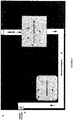
Figure 1 is a block flow diagram of an embodiment of a remote power source apparatus; -
Figure 2 is a block flow diagram of a further embodiment of a remote power source apparatus showing an expanded view of a fuel cell unit; and -
Figure 3 is a block flow diagram of a further embodiment of a remote power source apparatus including a heat exhaust structure. - Referring to
Figures 1 and2 , an embodiment of apower source apparatus 10 is shown. The components ofapparatus 10 compriseenclosure 20 surrounding afuel cell 30, and a water collection/condensation chamber 40.Enclosure 20 comprises anoutlet 22. In some embodiments,enclosure 20 can comprise vents and/or anair intake 24. Eitherair intake 24,outlet 22, or both can comprise adjustable vents to regulate the amount of air entering or exitingenclosure 20. - In some embodiments,
enclosure 20 can both house and protectfuel cell 30 as well as enclose operational equipment and connections required to runfuel cell 30 orfuel cell unit 31.Enclosure 20 can comprise insulation to retain heat emitted fromfuel cell 30 orfuel cell unit 31 withinenclosure 20. In some embodiments, the insulation ofenclosure 20 can be non-uniform. In some embodiments,chamber 40 can be disposed withinenclosure 20 in an area of lower insulation. In other words, the area ofenclosure 20proximate chamber 40 can be less insulated than other areas ofenclosure 20. This differential insulation, and the lack of proximity tofuel cell 30 orfuel cell unit 31 , can result in a colder region of enclosure forming aroundchamber 40 when the temperature external toenclosure 20 is lower than the ambient (internal) temperature ofenclosure 20. - In some embodiments, the majority of space available internal to
enclosure 20, excluding internal components, can be filled with insulation. The insulation type can comprise a variety of forms of insulation where the overall R-value of the insulation provides at least R10 value to the internal components. The exterior material ofenclosure 20 can be designed to protect components internal toenclosure 20. As would be understood by one skilled in the art, the exterior material can comprise a variety of forms from moulded plastic to aluminium. In some embodiments, the exterior material can be rated to function in at least -55°C. In some embodiments, for extreme conditions,enclosure 20 can comprise a double-walled housing to provide increased protection as well as added insulation R-value to the system. -
Fuel cell 30 can comprisecathode 32 andanode 34. As would be understood by one skilled in the art, in some embodiments,multiple fuel cells 30 can be arranged together as a fuel cell stack without departing from the function ofapparatus 10. In some embodiments,fuel cell 30 can be operatively coupled to a process condenser 60 with fan to control condensation rate and a water-gas separator tank 70 to form operatingfuel cell unit 31. - In some embodiments,
fuel cell 30 can be a direct methanol fuel cell (DMFC), although it would be understood by one skilled in the art that any appropriate fuel cell may be substituted. For example, other cells, including Polymer Electrolyte Membrane (PEM) fuel cells, which tend to operate with low temperatures and have water as a by-product can be substituted. Some known PEM fuel cells include hydrogen PEM fuel cells, Direct Ethanol Fuel Cells (DEFCs) and Direct Formic Acid Fuel Cells (DFAFCs). In some embodiments, for eachcell 30, two chemical half reactions occur to make the net reaction shown below.
Anode Half Reaction: CH3OH(I) + H20(I) → CO2 + 6 H+ + 6e-
Cathode Half Reaction: 3/2 O2 + 6 H+ + 6 e- -> 3 H2O(v)
Net Redox Reaction: CH3OH(I) + 3/2 O2 → CO2 + 2 H2O(v)
where water vapour and excess air can exit fuel cell orfuel cell unit 31 though a cathodefuel cell exhaust 36. CO2 produced by the reaction atanode 34 can exit through an anode outlet 38. - In some embodiments,
water condensing chamber 40 can comprise a container to collect and store water. Thewater condensing chamber 40 is internal toenclosure 20. In some embodiments,water condensing chamber 40 can be made of plastics, rust-proof/water-resistant metal, or other appropriate materials.Water condensing chamber 40 can be rectangular, cylindrical or any other appropriate shape. In some embodiments, the size thechamber 40 is determined by an amount of fuel supplied tofuel cell 30, such that the container is calibrated to receive the appropriate amount of water as a by-product.Water condensing chamber 40 can be positioned next to, above, or belowfuel cell 30. It would be understood by one skilled in the art that the characteristics ofwater condensing chamber 40 may be varied or substituted while maintaining the same function and without departing from the scope intended.Water condensing chamber 40 is connected to afirst tube 42 and is connected to asecond tube 44.Tubes tubes tubes water condensing chamber 40 can be sealed with the exception ofchamber inlet 46 andchamber outlet 48.Chamber inlet 46 andchamber outlet 48 are located on the top ofcondenser 40. One end offirst tube 42 is connected to fuelcell exhaust outlet 36 offuel cell 30 orfuel cell unit 31 and a second end offirst tube 42 is connected tochamber inlet 46. One end ofsecond tube 44 is connected tochamber outlet 48 and a second end ofsecond tube 44 can be connected toenclosure 20, proximate tooutlet 22. - In operation,
apparatus 10 can provide electricity to maintain sufficient charge in external batteries used to power electrical devices such as: communication repeaters, air monitors, water monitors, weather monitors, seismic monitors, remote surveillance, remote internet and cellular phone systems, signal boosters, chemical injection pumps, compression systems, remote portable power systems, electronic shut down devices, man down repeater stations, LED lighting solutions, video and communication packages, camera and filming power sources, wildlife monitoring systems. In some embodiments, devices such as these can be connected to a battery bank system that can be maintained and kept charged by the fuel cell system.Fuel cell 30 orfuel cell unit 31 produces water vapour as a by-product. This water vapour exitsfuel cell 30 orfuel cell unit 31 throughfuel cell exhaust 36 intofirst tube 42 and intowater condensing chamber 40 throughchamber inlet 46. In some embodiments, a U-tube effect should not be allowed in either tube in order to prevent condensed water from forming a plug. In some embodiments, the local temperature aroundwater condensing chamber 40 can be reduced, for example, due to the distance from the heat generated byfuel cell 30 orfuel cell unit 31, or due to less local insulation ofenclosure 20. A reduced local temperature can allow collected water vapour to condense into liquid water at the bottom ofwater condensing chamber 40. Furthermore, a pressure drop associated with connecting pressurized exhaust fromfirst tube 42 to an ambient pressure ofwater condensing chamber 40 further facilitates condensation. In some embodiments, the reduced local temperature ofenclosure 20, within the vicinity of excess condensingchamber 40 can be below 0°C. In some embodiments, liquid water condensed inwater condensing chamber 40 can freeze into ice. In some embodiments, condensed water can be stored inchamber 40 as water or ice. - Low moisture air and water vapour that has not condensed in
water condensing chamber 40, can exit throughchamber outlet 48 intosecond tube 44 and outside of enclosure throughenclosure outlet 22. In some embodiments,enclosure outlet 22 can lead to the external environment. This venting can prevent pressure from building inwater condensing chamber 40. In some embodiments,chamber 40 is removable fromapparatus 10 and collected water or ice can be emptied fromchamber 40. One skilled it the art would recognize that including a manual or actuated purging system involving a pump or drain would not depart from the scope of this disclosure and the ability to empty the container as required. In some embodiments,chamber 40 can comprise a frost-free condensate pump (not shown) to allow for non- frozen water to be pumped fromchamber 40 at predetermined intervals to allow for longer autonomy or larger fuel sources to be used withoutchamber 40 being limited by the size or amount of fuel. Condensed fluid can be pumped out ofchamber 40 as required. Referring toFigure 2 , an embodiment ofapparatus 10 is shown wherewater condensing chamber 40 can be operatively coupled tofuel cell unit 31. As would be understood by one skilled in the art, the mechanical equipment which can be used to run operatingfuel cell unit 31 includes: a fuel cell or stack 30; anair pump 50; a process condenser 60 with fan to control condensation rate; a water-gas separator tank 70; amethanol solution tank 80; apure methanol supply 90 with afuel metering pump 92 and ananode circulation pump 100. Different sizes and types of tubing can be used to connect this equipment. Air filters and fuel filters (not shown in the figures) can be used to lengthen the life of the fuel cell stack. The apparatus, systems, and methods of the present invention can be used to extend the operating temperature offuel cell unit 31 up to 25°C lower. - Process condenser 60 can condense an initial amount of liquid water from the exhaust water vapour from
fuel cell 30. Water-gas separator 70 can separatefuel cell 30 exhaust gases and uncondensed water vapour from process condenser 60 from condensed water coming from process condenser 60 such that the gas is exhausted and condensed water is sent to amethanol solution tank 80. Water-gas separator 70 can use gravity and a difference in pressure between the containers to separate the gases and to bubble the carbon dioxide products up through condensed water and out, along with the excess air. Meanwhile, liquid water can fill the separator, up to an overflow level, at which point it can drain intomethanol solution tank 80. - Referring to
Figure 3 ,apparatus 10 comprisesheat exhaust structure 50. In some embodiments,heat exhaust structure 50 can comprise ambient air flow channels which extend throughout the interior ofenclosure 20. In some embodiments, channels can be formed by voids in insulation internal toenclosure 20. Internal insulation (shown as shaded area) can be any appropriate insulating material, for example, high density black poly-styrene foam insulation. In some embodiments, the insulation can be cut to fit insideenclosure 20 and it can also shapeheat exhaust structure 50 as channels cut out of the insulation to form a path of travel for the heat exhaust. - In operation, heat produced and emitted from
fuel cell 30 orfuel cell unit 31 during electricity production byfuel cell 30 can exit throughfuel cell exhaust 36 and be collected byheat exhaust structure 50. The warm ambient air ofheat exhaust structure 50 can help prevent the freezing of water in components internal toenclosure 20. In some embodiments,heat exhaust structure 50 can be structured below or aroundchamber 40. In some embodiments,heat exhaust structure 50 can be structured below or aroundcathode 32. Heat exhausted throughstructure 50 can maintain the temperature internal toenclosure 20 within a range. In some embodiments, the internal ambient temperate withinenclosure 20 can be -20°C to +35°C. The use of heat exhaust prevents freezing of components ofapparatus 10 internal toenclosure 20. In some embodiments, the use of heat exhaust can prevent freezing ofcathode outlet 32. In some embodiments,heat exhaust structure 50 can lead warm air through the interior ofenclosure 20 tooutlet 22. In some embodiments an exhaust fan can be present atoutlet 22 to facilitate venting of heat exhaust. In some embodiments, exhaust fan can be thermostatically controlled so the fan does not operate when not needed, for example when external temperatures are above 0°C. - In some embodiments,
second tube 44 can lead outsideenclosure 20 at ornear enclosure outlet 22. The warm ambient air ofheat exhaust structure 50 can help prevent the freezing ofsecond tube 44. - Although a few embodiments have been shown and described, it will be appreciated by those skilled in the art that various changes and modifications might be made without departing from the scope of the invention as defined by the claims. The terms and expressions used in the preceding specification have been used herein as terms of description and not of limitation, and there is no intention in the use of such terms and expressions of excluding equivalents of the features shown and described or portions thereof, it being recognized that the invention is defined and limited only by the claims that follow.
Claims (11)
- A fuel cell system comprising:at least one fuel cell (30) or fuel cell unit (31) comprising a cathode exhaust outlet (36); andan apparatus (10) for operating the at least one fuel cell (30) or fuel cell unit (31), the apparatus comprising:a first tube (42) with one end operatively connected to the exhaust outlet (36), the first tube (42) configured for collecting water from the exhaust outlet (36);a chamber (40) operatively connected to a second end of the first tube (42);an enclosure (20) surrounding the chamber (40) and the cell (30) or unit (31) for capturing heat emitted from the cell (30) or unit (31), the enclosure (20) comprising an enclosure outlet (22); anda second tube (44) leading from the top of the chamber (40) to the enclosure outlet (22),wherein the chamber (40) condenses and holds water and wherein the enclosure (20) collects heat emitted from the cell (30) or unit (31);characterized bya heat exhaust structure (50) to direct heat emitted from the cell (30) or unit (31) to a position proximate the chamber (40) to prevent freezing of water in components internal to the enclosure (20) if an internal ambient temperature within the enclosure (20) is - 20°C;wherein the second end of the first tube (42) is operatively connected to the chamber (40) at the top of the chamber (40).
- The fuel cell system of claim 1 wherein the enclosure further comprises insulation to retain heat emitted from the fuel cell or fuel cell unit within the enclosure.
- The fuel cell system of claim 2 wherein the insulation is non-uniform within the enclosure.
- The fuel cell system of claim 3 wherein the chamber is disposed within the enclosure in an area of lower insulation.
- The fuel cell system of any of claims 1 to 4 wherein the heat exhaust structure is adapted to direct heat emitted from the cell or unit to a position proximate the enclosure outlet.
- The fuel cell system of any of claims 1 to 5 wherein the chamber is removable from the apparatus and wherein the water can be emptied from the chamber.
- The fuel cell system of any of claims 1 to 6 wherein the fuel cell or fuel cell unit comprises a polymer electrolyte membrane (PEM) fuel cell and/or a direct-methanol fuel cell.
- The fuel cell system of any of claims 1 to 6 wherein the chamber is positioned below the cell or unit.
- A method for operating at least one fuel cell (30) or fuel cell unit (31) comprising a cathode exhaust outlet (36), the method comprising the steps of:enclosing a chamber (40) and the cell or unit with an enclosure (20) surrounding the cell (30) or unit (31) for capturing heat emitted from the cell (30) or unit (31);receiving water vapour from the exhaust outlet (36) produced as a by-product of electricity production within the cell or unit;condensing at least a portion of the water vapour within the chamber (40) into water; andventing non-condensed water vapour from the chamber (40);further comprising the step of producing heat from the cell or unit as a by-product of electricity production and collecting the heat within the enclosure (20) surrounding the cell or unit;characterized bydirecting the heat proximate the chamber (40) via a heat exhaust structure (50) to prevent freezing of water in components internal to the enclosure (20) in the chamber (40) if an internal ambient temperature within the enclosure (20) is - 20°C; andconnecting pressurized exhaust to an ambient pressure of the chamber (40) to facilitate condensation.
- The method of claim 9 further comprising the step of
storing the water collected in the chamber within the enclosure. - The method of any of claims 9 to 10 further comprising the step of
removing and emptying water collected in the chamber as required.
Applications Claiming Priority (1)
| Application Number | Priority Date | Filing Date | Title |
|---|---|---|---|
| PCT/CA2011/001042 WO2013037031A1 (en) | 2011-09-16 | 2011-09-16 | Apparatus and methods for operating fuel cells in cold environments |
Publications (3)
| Publication Number | Publication Date |
|---|---|
| EP2756539A1 EP2756539A1 (en) | 2014-07-23 |
| EP2756539A4 EP2756539A4 (en) | 2015-05-06 |
| EP2756539B1 true EP2756539B1 (en) | 2018-11-07 |
Family
ID=47882475
Family Applications (1)
| Application Number | Title | Priority Date | Filing Date |
|---|---|---|---|
| EP11872436.8A Active EP2756539B1 (en) | 2011-09-16 | 2011-09-16 | Apparatus and method for operating fuel cells in cold environments |
Country Status (5)
| Country | Link |
|---|---|
| EP (1) | EP2756539B1 (en) |
| CA (1) | CA2846093C (en) |
| DK (1) | DK2756539T3 (en) |
| RU (1) | RU2570568C2 (en) |
| WO (1) | WO2013037031A1 (en) |
Families Citing this family (7)
| Publication number | Priority date | Publication date | Assignee | Title |
|---|---|---|---|---|
| JP6706160B2 (en) * | 2016-06-24 | 2020-06-03 | 株式会社フジクラ | Fuel cell system |
| JP7185960B2 (en) * | 2018-08-30 | 2022-12-08 | ワット・フューエル・セル・コーポレイション | Reformer vessel and fuel cell system |
| RU2722751C1 (en) * | 2019-12-10 | 2020-06-03 | Федеральное государственное бюджетное учреждение "Национальный исследовательский центр "Курчатовский институт" | Power plant with fuel cell for arctic zone |
| US11862831B2 (en) | 2021-12-28 | 2024-01-02 | Toyota Motor Engineering & Manufacturing North America, Inc. | Container for a fuel cell system |
| US12272846B2 (en) | 2021-12-28 | 2025-04-08 | Toyota Motor Engineering & Manufacturing North America, Inc. | Fuel cell system |
| US12166250B2 (en) | 2021-12-28 | 2024-12-10 | Toyota Motor Engineering & Manufacturing North America, Inc. | System and method for indirectly monitoring an isolation resistance of one or more fuel cells |
| US11962046B2 (en) | 2021-12-29 | 2024-04-16 | Toyota Motor Engineering & Manufacturing North America, Inc. | System and method for directly monitoring the conductivity of coolant used to regulate the temperature a fuel cell |
Family Cites Families (12)
| Publication number | Priority date | Publication date | Assignee | Title |
|---|---|---|---|---|
| US7727663B2 (en) * | 2001-07-18 | 2010-06-01 | Tel-Aviv University Future Technology Development L.P. | Fuel cell with proton conducting membrane and with improved water and fuel management |
| US6797421B2 (en) * | 2002-01-11 | 2004-09-28 | Utc Fuel Cells, Llc | Method and apparatus for preventing water in fuel cell power plants from freezing during storage |
| DE10307112A1 (en) * | 2002-02-19 | 2003-10-30 | Proton Energy Sys Inc | Energy storage and recovery system for electrochemical cell system, has pressure regulator provided between hydrogen generator and hydrogen storage device |
| JP4221942B2 (en) * | 2002-03-27 | 2009-02-12 | 日産自動車株式会社 | Fuel cell system |
| RU2264003C2 (en) * | 2002-05-10 | 2005-11-10 | Сони Корпорейшн | Fuel cell, power supply process using fuel cell, functional card, gas supply mechanism for fuel element, and gas generator |
| US20040062964A1 (en) * | 2002-09-30 | 2004-04-01 | Kabushiki Kaisha Toshiba | Direct methanol fuel cell system |
| JP3742053B2 (en) * | 2002-11-22 | 2006-02-01 | 株式会社東芝 | Fuel cell system |
| JP4886282B2 (en) * | 2005-11-30 | 2012-02-29 | 株式会社東芝 | Fuel cell unit |
| WO2007110587A2 (en) * | 2006-03-24 | 2007-10-04 | Ceres Intellectual Property Company Limited | Sofc stack system assembly with thermal enclosure |
| US7833672B2 (en) * | 2006-09-08 | 2010-11-16 | Samsung Sdi Co., Ltd. | Modular direct fuel cell system with integrated processor |
| EP2164123A1 (en) * | 2008-09-15 | 2010-03-17 | SFC Smart Fuel Cell AG | Increased water and heat recovery from a direct methanol fuel cell system |
| DE102009034380A1 (en) * | 2009-07-23 | 2011-01-27 | Daimler Ag | The fuel cell system |
-
2011
- 2011-09-16 RU RU2014115204/07A patent/RU2570568C2/en active
- 2011-09-16 DK DK11872436.8T patent/DK2756539T3/en active
- 2011-09-16 WO PCT/CA2011/001042 patent/WO2013037031A1/en not_active Ceased
- 2011-09-16 CA CA2846093A patent/CA2846093C/en active Active
- 2011-09-16 EP EP11872436.8A patent/EP2756539B1/en active Active
Non-Patent Citations (1)
| Title |
|---|
| None * |
Also Published As
| Publication number | Publication date |
|---|---|
| CA2846093C (en) | 2017-01-24 |
| CA2846093A1 (en) | 2013-03-21 |
| DK2756539T3 (en) | 2019-01-07 |
| WO2013037031A1 (en) | 2013-03-21 |
| EP2756539A4 (en) | 2015-05-06 |
| EP2756539A1 (en) | 2014-07-23 |
| RU2014115204A (en) | 2015-10-27 |
| RU2570568C2 (en) | 2015-12-10 |
Similar Documents
| Publication | Publication Date | Title |
|---|---|---|
| CA2846093C (en) | Apparatus and methods for operating fuel cells in cold environments | |
| AU2012228513B2 (en) | Hydrogen offloading in an electrochemical generator unit including a hydrogen fuel cell | |
| DK2686934T3 (en) | Independent hybrid power supply system for an electrical appliance, and device and method for controlling the system | |
| CN104170107B (en) | System, method and/or the equipment generated for thermoelectric power | |
| CN101567461A (en) | Hydrogen-immersed fuel cell stack and related operation | |
| CN110486166A (en) | Compressed air energy storage power generation method and compressed air energy storage power generation device | |
| US8748052B2 (en) | Reversible fuel cell | |
| KR20090086008A (en) | Insulation container for improving start-up and safety of fuel cell | |
| US20220074373A1 (en) | System and method for sustainable generation of energy | |
| RU2686844C1 (en) | Autonomous power plant | |
| US11784338B2 (en) | Integrated solar hydrogen production module | |
| JP6281402B2 (en) | Power system | |
| US10312539B1 (en) | System and method for storage and retrieval of energy | |
| JP2013109988A (en) | Fuel cell system | |
| US20080050636A1 (en) | Mixer for liquid fuels | |
| US20250357506A1 (en) | Fuel cell exhaust management | |
| JP6206312B2 (en) | Power system | |
| CN119895645A (en) | Gas management for metal air battery | |
| CN122051309A (en) | Liquid hydrogen fuel cell power supply system and electronic equipment | |
| JP2014110589A (en) | Monitor camera system | |
| Voigt | Clean Tech-the Next Big Business Thing? | |
| JP2015141869A (en) | Power supply system | |
| WO2010042985A1 (en) | Thermal storage device | |
| Orecchini et al. | Energy Conversion and Transformation Plants | |
| JP2015210915A (en) | Power supply system |
Legal Events
| Date | Code | Title | Description |
|---|---|---|---|
| PUAI | Public reference made under article 153(3) epc to a published international application that has entered the european phase |
Free format text: ORIGINAL CODE: 0009012 |
|
| 17P | Request for examination filed |
Effective date: 20140310 |
|
| AK | Designated contracting states |
Kind code of ref document: A1 Designated state(s): AL AT BE BG CH CY CZ DE DK EE ES FI FR GB GR HR HU IE IS IT LI LT LU LV MC MK MT NL NO PL PT RO RS SE SI SK SM TR |
|
| DAX | Request for extension of the european patent (deleted) | ||
| RA4 | Supplementary search report drawn up and despatched (corrected) |
Effective date: 20150410 |
|
| RIC1 | Information provided on ipc code assigned before grant |
Ipc: H01M 8/04 20060101AFI20150405BHEP Ipc: H01M 8/24 20060101ALI20150405BHEP |
|
| 17Q | First examination report despatched |
Effective date: 20160914 |
|
| STAA | Information on the status of an ep patent application or granted ep patent |
Free format text: STATUS: EXAMINATION IS IN PROGRESS |
|
| REG | Reference to a national code |
Ref country code: DE Ref legal event code: R079 Ref document number: 602011053765 Country of ref document: DE Free format text: PREVIOUS MAIN CLASS: H01M0008060000 Ipc: H01M0008247500 |
|
| GRAP | Despatch of communication of intention to grant a patent |
Free format text: ORIGINAL CODE: EPIDOSNIGR1 |
|
| STAA | Information on the status of an ep patent application or granted ep patent |
Free format text: STATUS: GRANT OF PATENT IS INTENDED |
|
| RIC1 | Information provided on ipc code assigned before grant |
Ipc: H01M 8/04014 20160101ALI20180420BHEP Ipc: H01M 8/2475 20160101AFI20180420BHEP Ipc: H01M 8/04119 20160101ALI20180420BHEP |
|
| INTG | Intention to grant announced |
Effective date: 20180529 |
|
| GRAS | Grant fee paid |
Free format text: ORIGINAL CODE: EPIDOSNIGR3 |
|
| GRAA | (expected) grant |
Free format text: ORIGINAL CODE: 0009210 |
|
| STAA | Information on the status of an ep patent application or granted ep patent |
Free format text: STATUS: THE PATENT HAS BEEN GRANTED |
|
| AK | Designated contracting states |
Kind code of ref document: B1 Designated state(s): AL AT BE BG CH CY CZ DE DK EE ES FI FR GB GR HR HU IE IS IT LI LT LU LV MC MK MT NL NO PL PT RO RS SE SI SK SM TR |
|
| REG | Reference to a national code |
Ref country code: GB Ref legal event code: FG4D |
|
| REG | Reference to a national code |
Ref country code: CH Ref legal event code: EP Ref country code: AT Ref legal event code: REF Ref document number: 1063176 Country of ref document: AT Kind code of ref document: T Effective date: 20181115 |
|
| REG | Reference to a national code |
Ref country code: IE Ref legal event code: FG4D |
|
| REG | Reference to a national code |
Ref country code: DE Ref legal event code: R096 Ref document number: 602011053765 Country of ref document: DE |
|
| REG | Reference to a national code |
Ref country code: DK Ref legal event code: T3 Effective date: 20190104 |
|
| REG | Reference to a national code |
Ref country code: NO Ref legal event code: T2 Effective date: 20181107 |
|
| REG | Reference to a national code |
Ref country code: NL Ref legal event code: MP Effective date: 20181107 |
|
| REG | Reference to a national code |
Ref country code: SE Ref legal event code: TRGR |
|
| REG | Reference to a national code |
Ref country code: LT Ref legal event code: MG4D |
|
| PG25 | Lapsed in a contracting state [announced via postgrant information from national office to epo] |
Ref country code: BG Free format text: LAPSE BECAUSE OF FAILURE TO SUBMIT A TRANSLATION OF THE DESCRIPTION OR TO PAY THE FEE WITHIN THE PRESCRIBED TIME-LIMIT Effective date: 20190207 Ref country code: LT Free format text: LAPSE BECAUSE OF FAILURE TO SUBMIT A TRANSLATION OF THE DESCRIPTION OR TO PAY THE FEE WITHIN THE PRESCRIBED TIME-LIMIT Effective date: 20181107 Ref country code: IS Free format text: LAPSE BECAUSE OF FAILURE TO SUBMIT A TRANSLATION OF THE DESCRIPTION OR TO PAY THE FEE WITHIN THE PRESCRIBED TIME-LIMIT Effective date: 20190307 Ref country code: ES Free format text: LAPSE BECAUSE OF FAILURE TO SUBMIT A TRANSLATION OF THE DESCRIPTION OR TO PAY THE FEE WITHIN THE PRESCRIBED TIME-LIMIT Effective date: 20181107 Ref country code: HR Free format text: LAPSE BECAUSE OF FAILURE TO SUBMIT A TRANSLATION OF THE DESCRIPTION OR TO PAY THE FEE WITHIN THE PRESCRIBED TIME-LIMIT Effective date: 20181107 Ref country code: LV Free format text: LAPSE BECAUSE OF FAILURE TO SUBMIT A TRANSLATION OF THE DESCRIPTION OR TO PAY THE FEE WITHIN THE PRESCRIBED TIME-LIMIT Effective date: 20181107 |
|
| PG25 | Lapsed in a contracting state [announced via postgrant information from national office to epo] |
Ref country code: PT Free format text: LAPSE BECAUSE OF FAILURE TO SUBMIT A TRANSLATION OF THE DESCRIPTION OR TO PAY THE FEE WITHIN THE PRESCRIBED TIME-LIMIT Effective date: 20190307 Ref country code: AL Free format text: LAPSE BECAUSE OF FAILURE TO SUBMIT A TRANSLATION OF THE DESCRIPTION OR TO PAY THE FEE WITHIN THE PRESCRIBED TIME-LIMIT Effective date: 20181107 Ref country code: GR Free format text: LAPSE BECAUSE OF FAILURE TO SUBMIT A TRANSLATION OF THE DESCRIPTION OR TO PAY THE FEE WITHIN THE PRESCRIBED TIME-LIMIT Effective date: 20190208 Ref country code: RS Free format text: LAPSE BECAUSE OF FAILURE TO SUBMIT A TRANSLATION OF THE DESCRIPTION OR TO PAY THE FEE WITHIN THE PRESCRIBED TIME-LIMIT Effective date: 20181107 Ref country code: NL Free format text: LAPSE BECAUSE OF FAILURE TO SUBMIT A TRANSLATION OF THE DESCRIPTION OR TO PAY THE FEE WITHIN THE PRESCRIBED TIME-LIMIT Effective date: 20181107 |
|
| REG | Reference to a national code |
Ref country code: AT Ref legal event code: UEP Ref document number: 1063176 Country of ref document: AT Kind code of ref document: T Effective date: 20181107 |
|
| PG25 | Lapsed in a contracting state [announced via postgrant information from national office to epo] |
Ref country code: IT Free format text: LAPSE BECAUSE OF FAILURE TO SUBMIT A TRANSLATION OF THE DESCRIPTION OR TO PAY THE FEE WITHIN THE PRESCRIBED TIME-LIMIT Effective date: 20181107 Ref country code: CZ Free format text: LAPSE BECAUSE OF FAILURE TO SUBMIT A TRANSLATION OF THE DESCRIPTION OR TO PAY THE FEE WITHIN THE PRESCRIBED TIME-LIMIT Effective date: 20181107 Ref country code: PL Free format text: LAPSE BECAUSE OF FAILURE TO SUBMIT A TRANSLATION OF THE DESCRIPTION OR TO PAY THE FEE WITHIN THE PRESCRIBED TIME-LIMIT Effective date: 20181107 |
|
| REG | Reference to a national code |
Ref country code: DE Ref legal event code: R097 Ref document number: 602011053765 Country of ref document: DE |
|
| PG25 | Lapsed in a contracting state [announced via postgrant information from national office to epo] |
Ref country code: SM Free format text: LAPSE BECAUSE OF FAILURE TO SUBMIT A TRANSLATION OF THE DESCRIPTION OR TO PAY THE FEE WITHIN THE PRESCRIBED TIME-LIMIT Effective date: 20181107 Ref country code: EE Free format text: LAPSE BECAUSE OF FAILURE TO SUBMIT A TRANSLATION OF THE DESCRIPTION OR TO PAY THE FEE WITHIN THE PRESCRIBED TIME-LIMIT Effective date: 20181107 Ref country code: RO Free format text: LAPSE BECAUSE OF FAILURE TO SUBMIT A TRANSLATION OF THE DESCRIPTION OR TO PAY THE FEE WITHIN THE PRESCRIBED TIME-LIMIT Effective date: 20181107 Ref country code: SK Free format text: LAPSE BECAUSE OF FAILURE TO SUBMIT A TRANSLATION OF THE DESCRIPTION OR TO PAY THE FEE WITHIN THE PRESCRIBED TIME-LIMIT Effective date: 20181107 |
|
| PLBE | No opposition filed within time limit |
Free format text: ORIGINAL CODE: 0009261 |
|
| STAA | Information on the status of an ep patent application or granted ep patent |
Free format text: STATUS: NO OPPOSITION FILED WITHIN TIME LIMIT |
|
| 26N | No opposition filed |
Effective date: 20190808 |
|
| PG25 | Lapsed in a contracting state [announced via postgrant information from national office to epo] |
Ref country code: SI Free format text: LAPSE BECAUSE OF FAILURE TO SUBMIT A TRANSLATION OF THE DESCRIPTION OR TO PAY THE FEE WITHIN THE PRESCRIBED TIME-LIMIT Effective date: 20181107 |
|
| PG25 | Lapsed in a contracting state [announced via postgrant information from national office to epo] |
Ref country code: TR Free format text: LAPSE BECAUSE OF FAILURE TO SUBMIT A TRANSLATION OF THE DESCRIPTION OR TO PAY THE FEE WITHIN THE PRESCRIBED TIME-LIMIT Effective date: 20181107 |
|
| PG25 | Lapsed in a contracting state [announced via postgrant information from national office to epo] |
Ref country code: MC Free format text: LAPSE BECAUSE OF FAILURE TO SUBMIT A TRANSLATION OF THE DESCRIPTION OR TO PAY THE FEE WITHIN THE PRESCRIBED TIME-LIMIT Effective date: 20181107 |
|
| REG | Reference to a national code |
Ref country code: CH Ref legal event code: PL |
|
| PG25 | Lapsed in a contracting state [announced via postgrant information from national office to epo] |
Ref country code: IE Free format text: LAPSE BECAUSE OF NON-PAYMENT OF DUE FEES Effective date: 20190916 Ref country code: LI Free format text: LAPSE BECAUSE OF NON-PAYMENT OF DUE FEES Effective date: 20190930 Ref country code: CH Free format text: LAPSE BECAUSE OF NON-PAYMENT OF DUE FEES Effective date: 20190930 Ref country code: LU Free format text: LAPSE BECAUSE OF NON-PAYMENT OF DUE FEES Effective date: 20190916 |
|
| REG | Reference to a national code |
Ref country code: BE Ref legal event code: MM Effective date: 20190930 |
|
| PG25 | Lapsed in a contracting state [announced via postgrant information from national office to epo] |
Ref country code: BE Free format text: LAPSE BECAUSE OF NON-PAYMENT OF DUE FEES Effective date: 20190930 |
|
| PG25 | Lapsed in a contracting state [announced via postgrant information from national office to epo] |
Ref country code: CY Free format text: LAPSE BECAUSE OF FAILURE TO SUBMIT A TRANSLATION OF THE DESCRIPTION OR TO PAY THE FEE WITHIN THE PRESCRIBED TIME-LIMIT Effective date: 20181107 |
|
| PG25 | Lapsed in a contracting state [announced via postgrant information from national office to epo] |
Ref country code: MT Free format text: LAPSE BECAUSE OF FAILURE TO SUBMIT A TRANSLATION OF THE DESCRIPTION OR TO PAY THE FEE WITHIN THE PRESCRIBED TIME-LIMIT Effective date: 20181107 Ref country code: HU Free format text: LAPSE BECAUSE OF FAILURE TO SUBMIT A TRANSLATION OF THE DESCRIPTION OR TO PAY THE FEE WITHIN THE PRESCRIBED TIME-LIMIT; INVALID AB INITIO Effective date: 20110916 |
|
| PG25 | Lapsed in a contracting state [announced via postgrant information from national office to epo] |
Ref country code: MK Free format text: LAPSE BECAUSE OF FAILURE TO SUBMIT A TRANSLATION OF THE DESCRIPTION OR TO PAY THE FEE WITHIN THE PRESCRIBED TIME-LIMIT Effective date: 20181107 |
|
| PGFP | Annual fee paid to national office [announced via postgrant information from national office to epo] |
Ref country code: FI Payment date: 20250930 Year of fee payment: 15 |
|
| PGFP | Annual fee paid to national office [announced via postgrant information from national office to epo] |
Ref country code: DE Payment date: 20250923 Year of fee payment: 15 Ref country code: DK Payment date: 20250923 Year of fee payment: 15 |
|
| PGFP | Annual fee paid to national office [announced via postgrant information from national office to epo] |
Ref country code: GB Payment date: 20250927 Year of fee payment: 15 |
|
| PGFP | Annual fee paid to national office [announced via postgrant information from national office to epo] |
Ref country code: FR Payment date: 20250926 Year of fee payment: 15 Ref country code: AT Payment date: 20250923 Year of fee payment: 15 |
|
| PGFP | Annual fee paid to national office [announced via postgrant information from national office to epo] |
Ref country code: SE Payment date: 20250927 Year of fee payment: 15 |
|
| PGFP | Annual fee paid to national office [announced via postgrant information from national office to epo] |
Ref country code: NO Payment date: 20251001 Year of fee payment: 15 |