EP2756241B2 - A cooling device comprising an insulation material that is provided to be distributed homogeneously in the insulation volume - Google Patents
A cooling device comprising an insulation material that is provided to be distributed homogeneously in the insulation volume Download PDFInfo
- Publication number
- EP2756241B2 EP2756241B2 EP12759448.9A EP12759448A EP2756241B2 EP 2756241 B2 EP2756241 B2 EP 2756241B2 EP 12759448 A EP12759448 A EP 12759448A EP 2756241 B2 EP2756241 B2 EP 2756241B2
- Authority
- EP
- European Patent Office
- Prior art keywords
- wall
- insulation material
- insulation
- regulating member
- cooling device
- Prior art date
- Legal status (The legal status is an assumption and is not a legal conclusion. Google has not performed a legal analysis and makes no representation as to the accuracy of the status listed.)
- Active
Links
Images

Classifications
-
- F—MECHANICAL ENGINEERING; LIGHTING; HEATING; WEAPONS; BLASTING
- F25—REFRIGERATION OR COOLING; COMBINED HEATING AND REFRIGERATION SYSTEMS; HEAT PUMP SYSTEMS; MANUFACTURE OR STORAGE OF ICE; LIQUEFACTION SOLIDIFICATION OF GASES
- F25D—REFRIGERATORS; COLD ROOMS; ICE-BOXES; COOLING OR FREEZING APPARATUS NOT OTHERWISE PROVIDED FOR
- F25D23/00—General constructional features
- F25D23/02—Doors; Covers
-
- F—MECHANICAL ENGINEERING; LIGHTING; HEATING; WEAPONS; BLASTING
- F25—REFRIGERATION OR COOLING; COMBINED HEATING AND REFRIGERATION SYSTEMS; HEAT PUMP SYSTEMS; MANUFACTURE OR STORAGE OF ICE; LIQUEFACTION SOLIDIFICATION OF GASES
- F25D—REFRIGERATORS; COLD ROOMS; ICE-BOXES; COOLING OR FREEZING APPARATUS NOT OTHERWISE PROVIDED FOR
- F25D23/00—General constructional features
- F25D23/06—Walls
- F25D23/062—Walls defining a cabinet
- F25D23/064—Walls defining a cabinet formed by moulding, e.g. moulding in situ
-
- F—MECHANICAL ENGINEERING; LIGHTING; HEATING; WEAPONS; BLASTING
- F25—REFRIGERATION OR COOLING; COMBINED HEATING AND REFRIGERATION SYSTEMS; HEAT PUMP SYSTEMS; MANUFACTURE OR STORAGE OF ICE; LIQUEFACTION SOLIDIFICATION OF GASES
- F25D—REFRIGERATORS; COLD ROOMS; ICE-BOXES; COOLING OR FREEZING APPARATUS NOT OTHERWISE PROVIDED FOR
- F25D2201/00—Insulation
- F25D2201/10—Insulation with respect to heat
- F25D2201/12—Insulation with respect to heat using an insulating packing material
- F25D2201/126—Insulation with respect to heat using an insulating packing material of cellular type
Definitions
- the present invention relates to a cooling device comprising an insulation material that is provided to be distributed homogeneously in the insulation volume.
- an insulation material is filled between the inner and outer walls of the body in order to provide heat insulation between the inner volume and the outer environment. Due to its chemical structure, the insulation material, that is preferably polyurethane, expands and solidifies once it is filled into the body of the cooling device. During this solidification, gaps occur in the insulation material. At the ceiling that is the section the insulation material reaches last, these gaps occur more frequently and cause the sheet metal of the cooling device to collapse towards the section with gaps. These collapses are considered as malfunction by the user and this situation both increases maintenance costs and also distorts the quality perception of the user.
- the insulation material that is preferably polyurethane
- quick-solidifying polyurethane is used as the insulation material in order to speed up the body-insulation process and this causes an increase in the number of the gaps.
- slow-solidifying polyurethane is used in order to prevent collapses on the surface of the body, the production slows down and efficiency decreases.
- a cooling device wherein the insulation material is provided to be homogeneously distributed by means of the plates placed to the inner side of the inner wall of the body, contacting the insulation material.
- a solidified epoxy layer and an intermediary resin layer are disposed between the inner wall and the insulation material.
- a heat insulation wall is described, wherein the top is left open, and after the insulation material is filled therein and pressed by means of a pressing means, the top is closed.
- the heat insulation wall is the refrigerator door.
- the aim of the present invention is the realization of a cooling device wherein the gaps in the insulation material filled into the insulation volume are eliminated.
- the cooling device realized in order to attain the aim of the present invention, is defined in independent claim 1.
- the insulation material is preferably polyurethane.
- the insulation material filled into the insulation volume through an opening arranged on the outer wall splits into smaller pieces by passing through the holes on the regulating members and thus the number of air gaps occurring during the solidification of the insulation material is decreased.
- the regulating member is placed to the inner side of the inner wall, contacting the insulation material.
- the regulating member extends along the surface it is covered on, almost parallel to the inner wall and the outer wall.
- the regulating member is net-shaped.
- the regulating member can be easily shaped and is formed in compliance with the structure of the wall where it will be placed.
- the regulating member can be stored in rolls, can be shaped and used according to the geometry of the section where it will be used. Thus, storing costs are decreased. Moreover, since it is not needed to use different molds for different sections of the body, saving in mold costs is provided.
- the regulating member is placed to the ceiling.
- the insulation material that starts solidifying before reaching the ceiling is provided to flow in small pieces upon reaching the ceiling and big gaps that start being formed break into pieces.
- the frequently-encountered problem of the collapsing of the ceiling is prevented.
- the regulating member is placed into an intermediary wall that separates the body into compartments.
- the regulating member is placed into a door providing access into the body.
- the regulating member is placed between the inner wall and the outer wall and provides the insulation material to be homogeneously distributed inside the door, thus providing the surface of the door to be smooth.
- two regulating members are placed at intervals between the inner wall and the outer wall so as to be parallel to each other.
- One of the regulating members is closer to the inner wall, and the other to the outer wall.
- the holes on the regulating member that is closer to the inner wall are smaller than the holes on the regulating member that is closer to the outer wall.
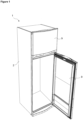
- the cooling device (1) comprises a body (2) having an inner wall (3), an outer wall (4), an insulation volume (5) between the inner wall (3) and the outer wall (4) and an insulation material (6) filled into the insulation volume (5) ( Figure 1 , Figure 3 ).
- an opening (O) is arranged so that the insulation material (6) can be filled into the insulation volume (5).
- the insulation material (6) that is filled preferably through a single opening (O), reaches almost every section of the insulation volume (5) thanks to its fluid structure.
- the insulation material (6) that is composed of more than one chemical substance enters into exothermic reaction and solidifies as expanding.
- the interior volume of the cooling device (1) is provided to be insulated from the outer environment conditions and the durability of the body (2) is increased.
- the cooling device (1) comprises at least one perforated regulating member (7) that is placed into the insulation volume (5) and that prevents the formation of gaps by regulating the flow of the insulation material (6).
- the insulation material (6) splits into smaller pieces by passing through the holes of the regulating member (7).
- the number of gaps being formed during the solidification is minimized, and the inner wall (3) is prevented from collapsing towards the outer wall (4) in course of time. This provides the malfunction-occurrence rate to decrease and the quality perception to increase.
- quick-solidifying insulation material (6) can be used, and this shortens the production time, thereby increasing efficiency.
- the regulating member (7) is placed on the face of the inner wall (3) facing the insulation volume (5). After the regulating member (7) is fastened onto the inner wall (3) from its edges, the insulation material (6) is filled into the insulation volume (5) through the opening (O) preferably arranged on the outer wall (4). Thus, the insulation material (6) is provided to be solidified at the section just above the inner wall (3) without formation of gaps, and collapses on the inner surface of the cooling device (1) are prevented.
- the regulating member (7) is placed into the insulation volume (5) so as to be almost parallel to the inner wall (3) and the outer wall (4).
- the regulating member (7) is net-shaped.
- the regulating member (7) can be easily shaped depending on the geometry of the surface it will be used.
- mold and logistic costs are decreased since it is not needed to produce and store regulating members (7) with different shapes for different sections of the body (2).
- cost advantage and production flexibility are provided ( Figure 2 ).
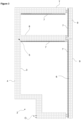
- the regulating member (7) is placed at the ceiling (T) section of the inner wall (3), throughout the ceiling (T).
- the regulating member (7) is fastened to the ceiling (T) section of the inner wall (3) from its edges so as to cover the entire ceiling (T).
- the insulation material (6) is provided to be homogeneously distributed at the ceiling (T) where the insulation material (6) filled through the opening (O) located at the bottom of the body (2) reaches last, and possible collapses are prevented ( Figure 2 ).
- the body (2) comprises at least one intermediary wall (8) that divides the body into compartments and the regulating member (7) is placed into the intermediary wall (8).
- the insulation material (6) is homogeneously distributed over the surfaces of the intermediary wall (8) covered with the regulating member (7) and a smooth appearance is obtained ( Figure 3 ).
- one regulating member (7) is disposed on each of the faces of the intermediary wall (8) facing both compartments.
- the body (2) comprises at least one door (9) providing access therein and the regulating member (7) is placed into the door (9).
- the insulation material (6) is provided to be homogeneously distributed inside the door (9) and outer appearance is improved by preventing the occurrence of collapses on the surface of the door (9) ( Figure 3 ).
- the cooling device (1) comprises two regulating members (7) that are positioned to be spaced apart from each other.
- the regulating members (7) are placed into the insulation volume (5) so as to be parallel to each other.
- polyurethane is preferably used as the insulation material.
- the inner wall contacting the insulation material is prevented from collapsing towards the outer wall due to the gaps that may occur because of the quick-solidification of the insulation material.
- the outer appearance of the cooling device is improved and the number of malfunction-records that may occur due to the collapses on the surface is provided to be decreased.
- per-product production time is decreased, thereby increasing the production efficiency.
Landscapes
- Engineering & Computer Science (AREA)
- Chemical & Material Sciences (AREA)
- Combustion & Propulsion (AREA)
- Physics & Mathematics (AREA)
- Mechanical Engineering (AREA)
- Thermal Sciences (AREA)
- General Engineering & Computer Science (AREA)
- Refrigerator Housings (AREA)
Description
- The present invention relates to a cooling device comprising an insulation material that is provided to be distributed homogeneously in the insulation volume.
- In cooling devices, especially in refrigerators and freezers, an insulation material is filled between the inner and outer walls of the body in order to provide heat insulation between the inner volume and the outer environment. Due to its chemical structure, the insulation material, that is preferably polyurethane, expands and solidifies once it is filled into the body of the cooling device. During this solidification, gaps occur in the insulation material. At the ceiling that is the section the insulation material reaches last, these gaps occur more frequently and cause the sheet metal of the cooling device to collapse towards the section with gaps. These collapses are considered as malfunction by the user and this situation both increases maintenance costs and also distorts the quality perception of the user. In some embodiments, quick-solidifying polyurethane is used as the insulation material in order to speed up the body-insulation process and this causes an increase in the number of the gaps. When slow-solidifying polyurethane is used in order to prevent collapses on the surface of the body, the production slows down and efficiency decreases.
- In the state of the art Japanese Patent Application No.
JP9303947 - In the state of the art Japanese Patent Application No.
JP9303947 - In
DE 10 2008 043 284 A1 a cooling device according to the preamble ofclaim 1 is disclosed. In this prior art document, an element is inserted in the opening for injection of insulation material in order to achieve a homogenous filling of the insulation volume with the insulation material. - In
DE19923382A1 a cooling device according to the preamble ofclaim 1 is disclosed. - The aim of the present invention is the realization of a cooling device wherein the gaps in the insulation material filled into the insulation volume are eliminated.
- The cooling device realized in order to attain the aim of the present invention, is defined in
independent claim 1. The insulation material is preferably polyurethane. The insulation material filled into the insulation volume through an opening arranged on the outer wall splits into smaller pieces by passing through the holes on the regulating members and thus the number of air gaps occurring during the solidification of the insulation material is decreased. - In an embodiment not according to the present invention, the regulating member is placed to the inner side of the inner wall, contacting the insulation material. Thus, formation of collapses on the outer surfaces of the inner wall facing the inner volume of the cooling device, is prevented.
- In another embodiment not according to the present invention, the regulating member extends along the surface it is covered on, almost parallel to the inner wall and the outer wall.
- In another embodiment not according to the present invention, the regulating member is net-shaped. In this embodiment, the regulating member can be easily shaped and is formed in compliance with the structure of the wall where it will be placed. The regulating member can be stored in rolls, can be shaped and used according to the geometry of the section where it will be used. Thus, storing costs are decreased. Moreover, since it is not needed to use different molds for different sections of the body, saving in mold costs is provided.
- In another embodiment not according to the present invention, the regulating member is placed to the ceiling. Thus, the insulation material that starts solidifying before reaching the ceiling, is provided to flow in small pieces upon reaching the ceiling and big gaps that start being formed break into pieces. Thus, the frequently-encountered problem of the collapsing of the ceiling is prevented.
- In a derivative of this embodiment, the regulating member is placed into an intermediary wall that separates the body into compartments.
- In another embodiment not according to the present invention, the regulating member is placed into a door providing access into the body. In this embodiment, the regulating member is placed between the inner wall and the outer wall and provides the insulation material to be homogeneously distributed inside the door, thus providing the surface of the door to be smooth.
- According to the present invention, two regulating members are placed at intervals between the inner wall and the outer wall so as to be parallel to each other. One of the regulating members is closer to the inner wall, and the other to the outer wall. In a derivative of this embodiment, the holes on the regulating member that is closer to the inner wall are smaller than the holes on the regulating member that is closer to the outer wall. Thus, the flow of the insulation material is regulated gradually, and gap-formation is provided to be minimized.
- By means of the present invention, air gaps occurring during the solidification of the insulation material are eliminated and the inner wall is prevented from collapsing towards these gaps. Thus, malfunction-occurrence rate and maintenance costs are decreased, and the quality perception of the user is improved. Moreover, production efficiency is improved since quick-solidifying insulation material can be used.
- A cooling device not belonging to the present invention is illustrated in the attached figures, where:
-
Figure 1 - is the perspective view of a cooling device. -
Figure 2 - is the perspective view of the inner wall and the regulating member. -
Figure 3 - is the schematic view of the body. - The elements illustrated in the figures are numbered as follows:
- 1. Cooling device
- 2. Body
- 3. Inner wall
- 4. Outer wall
- 5. Insulation volume
- 6. Insulation material
- 7. Regulating member
- 8. Intermediary wall
- 9. Door
- The cooling device (1) comprises a body (2) having an inner wall (3), an outer wall (4), an insulation volume (5) between the inner wall (3) and the outer wall (4) and an insulation material (6) filled into the insulation volume (5) (
Figure 1 ,Figure 3 ). - While the inner wall (3) and the outer wall (4) is being joint during the production, an opening (O) is arranged so that the insulation material (6) can be filled into the insulation volume (5). The insulation material (6) that is filled preferably through a single opening (O), reaches almost every section of the insulation volume (5) thanks to its fluid structure. When filled into the insulation volume (5), the insulation material (6) that is composed of more than one chemical substance enters into exothermic reaction and solidifies as expanding. Thus, the interior volume of the cooling device (1) is provided to be insulated from the outer environment conditions and the durability of the body (2) is increased.
- The cooling device (1) comprises at least one perforated regulating member (7) that is placed into the insulation volume (5) and that prevents the formation of gaps by regulating the flow of the insulation material (6). Upon contacting the regulating member (7) while being filled into the insulation volume (5), the insulation material (6) splits into smaller pieces by passing through the holes of the regulating member (7). Thus, the number of gaps being formed during the solidification is minimized, and the inner wall (3) is prevented from collapsing towards the outer wall (4) in course of time. This provides the malfunction-occurrence rate to decrease and the quality perception to increase. Moreover, by means of eliminating the gaps being formed during the solidification of the insulation material (6), quick-solidifying insulation material (6) can be used, and this shortens the production time, thereby increasing efficiency.
- In an embodiment not according to the present invention, the regulating member (7) is placed on the face of the inner wall (3) facing the insulation volume (5). After the regulating member (7) is fastened onto the inner wall (3) from its edges, the insulation material (6) is filled into the insulation volume (5) through the opening (O) preferably arranged on the outer wall (4). Thus, the insulation material (6) is provided to be solidified at the section just above the inner wall (3) without formation of gaps, and collapses on the inner surface of the cooling device (1) are prevented.
- In another embodiment not according to the present invention, the regulating member (7) is placed into the insulation volume (5) so as to be almost parallel to the inner wall (3) and the outer wall (4).
- In another embodiment not according to the present invention, the regulating member (7) is net-shaped. Thus, the regulating member (7) can be easily shaped depending on the geometry of the surface it will be used. Thus, mold and logistic costs are decreased since it is not needed to produce and store regulating members (7) with different shapes for different sections of the body (2). Moreover, thanks to the low-cost and high availability of the net-shaped regulating member (7), cost advantage and production flexibility are provided (
Figure 2 ). - In another embodiment not according to the present invention, the regulating member (7) is placed at the ceiling (T) section of the inner wall (3), throughout the ceiling (T). In this embodiment, the regulating member (7) is fastened to the ceiling (T) section of the inner wall (3) from its edges so as to cover the entire ceiling (T). Thus, the insulation material (6) is provided to be homogeneously distributed at the ceiling (T) where the insulation material (6) filled through the opening (O) located at the bottom of the body (2) reaches last, and possible collapses are prevented (
Figure 2 ). - In another embodiment not according to the present invention, the body (2) comprises at least one intermediary wall (8) that divides the body into compartments and the regulating member (7) is placed into the intermediary wall (8). The insulation material (6) is homogeneously distributed over the surfaces of the intermediary wall (8) covered with the regulating member (7) and a smooth appearance is obtained (
Figure 3 ). In a derivative of this embodiment, one regulating member (7) is disposed on each of the faces of the intermediary wall (8) facing both compartments. - In another embodiment not according to the present invention, the body (2) comprises at least one door (9) providing access therein and the regulating member (7) is placed into the door (9). Thus, the insulation material (6) is provided to be homogeneously distributed inside the door (9) and outer appearance is improved by preventing the occurrence of collapses on the surface of the door (9) (
Figure 3 ). - In another embodiment not according to the present invention, the cooling device (1) comprises two regulating members (7) that are positioned to be spaced apart from each other. The regulating members (7) are placed into the insulation volume (5) so as to be parallel to each other.
- In the cooling device of the present invention, polyurethane is preferably used as the insulation material.
- By means of the present invention, the inner wall contacting the insulation material is prevented from collapsing towards the outer wall due to the gaps that may occur because of the quick-solidification of the insulation material. Thus, the outer appearance of the cooling device is improved and the number of malfunction-records that may occur due to the collapses on the surface is provided to be decreased. Moreover, since it becomes possible to use quick-solidifying insulation material, per-product production time is decreased, thereby increasing the production efficiency.
Claims (1)
- A cooling device (1) comprising a body (2) having an inner wall (3), an outer wall (4), an insulation volume (5) between the inner wall (3) and the outer wall (4), an insulation material (6) filled into the insulation volume (5), and at least one perforated regulating member (7) that is placed into the insulation volume (5) for preventing the formation of gaps by regulating the flow of the insulation material (6) during it being filled into the insulation volume (5), wherein said regulating member (7) has a plurality of holes and is configured and is placed into the insulation volume (5) in such a manner that insulation material (6) during it being filled into the insulation volume (5) splits into smaller pieces by passing through said holes of the regulating member (7), wherein two regulating members (7) are placed at intervals between the inner wall (3) and the outer wall (4) so as to be parallel to each other, wherein one of the regulating members (7) is closer to the inner wall (3), and the other to the outer wall (4), and characterised in that the holes on the regulating member (7) that is closer to the inner wall (3) are smaller than the holes on the regulating member (7) that is closer to the outer wall (4).
Priority Applications (1)
| Application Number | Priority Date | Filing Date | Title |
|---|---|---|---|
| PL12759448T PL2756241T3 (en) | 2011-09-16 | 2012-09-17 | A cooling device comprising an insulation material that is provided to be distributed homogeneously in the insulation volume |
Applications Claiming Priority (2)
| Application Number | Priority Date | Filing Date | Title |
|---|---|---|---|
| TR201109111 | 2011-09-16 | ||
| PCT/EP2012/068229 WO2013038003A2 (en) | 2011-09-16 | 2012-09-17 | A cooling device comprising an insulation material that is provided to be distributed homogeneously in the insulation volume |
Publications (3)
| Publication Number | Publication Date |
|---|---|
| EP2756241A2 EP2756241A2 (en) | 2014-07-23 |
| EP2756241B1 EP2756241B1 (en) | 2020-04-01 |
| EP2756241B2 true EP2756241B2 (en) | 2024-09-04 |
Family
ID=46852002
Family Applications (1)
| Application Number | Title | Priority Date | Filing Date |
|---|---|---|---|
| EP12759448.9A Active EP2756241B2 (en) | 2011-09-16 | 2012-09-17 | A cooling device comprising an insulation material that is provided to be distributed homogeneously in the insulation volume |
Country Status (4)
| Country | Link |
|---|---|
| EP (1) | EP2756241B2 (en) |
| CN (1) | CN103797318B (en) |
| PL (1) | PL2756241T3 (en) |
| WO (1) | WO2013038003A2 (en) |
Families Citing this family (5)
| Publication number | Priority date | Publication date | Assignee | Title |
|---|---|---|---|---|
| EP3052877A1 (en) * | 2013-10-03 | 2016-08-10 | Arçelik Anonim Sirketi | A cooling device comprising an insulation material homogeneously distributed in the insulation volume |
| EP3164652B1 (en) * | 2014-07-04 | 2020-04-01 | Arçelik Anonim Sirketi | A cooling device comprising a carrier |
| DE202015007214U1 (en) * | 2015-10-15 | 2015-11-23 | BSH Hausgeräte GmbH | Refrigerating appliance with expansion opening |
| TR201706514A2 (en) | 2017-05-03 | 2018-11-21 | Arcelik As | A COOLER THAT IS PROVIDED TO DISTRIBUTE INSULATION MATERIAL IN THE INSULATION VOLUME |
| TR201706505A3 (en) | 2017-05-03 | 2018-12-21 | Arcelik As | REFRIGERATOR WITH PLASTIC INNER WALL |
Family Cites Families (12)
| Publication number | Priority date | Publication date | Assignee | Title |
|---|---|---|---|---|
| US3132382A (en) * | 1962-09-13 | 1964-05-12 | Gen Electric | Resin foam insulated cabinet |
| GB1150555A (en) * | 1965-08-06 | 1969-04-30 | English Electric Co Ltd | Method of Filling a Cavity with a Foamed Material |
| US5560695A (en) * | 1991-08-26 | 1996-10-01 | Southco, Inc. | Venting device |
| DE29603848U1 (en) | 1996-03-01 | 1997-05-28 | Liebherr-Hausgeräte GmbH, 88416 Ochsenhausen | Refrigerator with a cooling compartment and a cold storage compartment |
| JPH09303947A (en) | 1996-05-15 | 1997-11-28 | Matsushita Electric Ind Co Ltd | Insulation box and method of manufacturing insulation box |
| DE19854231A1 (en) * | 1998-11-24 | 2000-05-25 | Bsh Bosch Siemens Hausgeraete | Multi-temperature refrigerator |
| US6228485B1 (en) * | 1999-04-30 | 2001-05-08 | Flexipak Distributin, Llc | Venting tape |
| DE19923382A1 (en) | 1999-05-21 | 2000-11-23 | Bsh Bosch Siemens Hausgeraete | Heat-insulating wall, like refrigerator housing, refrigerator door or similar has inner and/or outer cladding provided on side facing thermally insulating layer with devices |
| DE202004020115U1 (en) | 2004-12-29 | 2006-05-11 | Liebherr-Hausgeräte Ochsenhausen GmbH | cooling unit |
| DE102006059387A1 (en) * | 2006-11-30 | 2008-06-05 | Liebherr-Hausgeräte Ochsenhausen GmbH | Construction unit, in particular heat insulating construction unit, in particular cooling or freezing equipment, has foam filled hollow space that is in connection with hollow body |
| DE102008043284A1 (en) * | 2008-10-29 | 2010-05-06 | BSH Bosch und Siemens Hausgeräte GmbH | Refrigerator, particularly household refrigerator, has heat insulated housing, which has external casing and inner casing, which form gap, in which heat insulating material is brought in fluidic source components over insertion opening |
| CN201837182U (en) * | 2010-07-16 | 2011-05-18 | 合肥美的荣事达电冰箱有限公司 | Refrigerator water supply device and refrigerator with same |
-
2012
- 2012-09-17 PL PL12759448T patent/PL2756241T3/en unknown
- 2012-09-17 EP EP12759448.9A patent/EP2756241B2/en active Active
- 2012-09-17 WO PCT/EP2012/068229 patent/WO2013038003A2/en not_active Ceased
- 2012-09-17 CN CN201280044873.1A patent/CN103797318B/en active Active
Also Published As
| Publication number | Publication date |
|---|---|
| EP2756241B1 (en) | 2020-04-01 |
| CN103797318A (en) | 2014-05-14 |
| EP2756241A2 (en) | 2014-07-23 |
| PL2756241T3 (en) | 2020-10-19 |
| CN103797318B (en) | 2016-06-22 |
| WO2013038003A3 (en) | 2013-08-29 |
| WO2013038003A2 (en) | 2013-03-21 |
Similar Documents
| Publication | Publication Date | Title |
|---|---|---|
| EP2756241B2 (en) | A cooling device comprising an insulation material that is provided to be distributed homogeneously in the insulation volume | |
| KR101758277B1 (en) | Refrigerater | |
| JP6091825B2 (en) | refrigerator | |
| JP5869559B2 (en) | Extruded material overmolding | |
| US9656415B2 (en) | Device for producing molded parts from particulate plastic materials | |
| JP5503478B2 (en) | refrigerator | |
| JP2013249973A (en) | Refrigerator | |
| JP5620764B2 (en) | refrigerator | |
| CN102121781A (en) | Filling airbag component, refrigerator and refrigeration equipment | |
| JP5548076B2 (en) | Refrigerator and vacuum insulation | |
| JP6117544B2 (en) | refrigerator | |
| KR101348602B1 (en) | Aluminum complex prevention defomation sheet for refrigerator door and manufacturing method thereof | |
| WO2015049236A1 (en) | A cooling device comprising an insulation material homogeneously distributed in the insulation volume | |
| KR20160002481U (en) | Ice Stick Machine | |
| WO2018202370A1 (en) | A cooler in which the insulation material is distributed in the insulation volume | |
| CN1243946C (en) | Insulated enclosures for refrigeration units | |
| JP2014043987A (en) | Refrigerator | |
| JP2013204900A (en) | Heat insulating box and refrigerator with the same | |
| EP3164652B1 (en) | A cooling device comprising a carrier | |
| CN109790797B (en) | Thermal insulation tool for cylinder bore wall, internal combustion engine and automobile | |
| EP4177554B1 (en) | A cooling device | |
| KR100564341B1 (en) | How to Fix Inner Case for Refrigeration / Refrigerator | |
| CN218511285U (en) | Main control board box for refrigeration equipment, prefabricated body of refrigeration equipment and refrigeration equipment | |
| RS63352B1 (en) | PROCEDURE FOR EXTRUSION OF EXPANDED POLYMER FILMS | |
| EP2304354B1 (en) | A method for making a cooling device |
Legal Events
| Date | Code | Title | Description |
|---|---|---|---|
| PUAI | Public reference made under article 153(3) epc to a published international application that has entered the european phase |
Free format text: ORIGINAL CODE: 0009012 |
|
| 17P | Request for examination filed |
Effective date: 20131216 |
|
| AK | Designated contracting states |
Kind code of ref document: A2 Designated state(s): AL AT BE BG CH CY CZ DE DK EE ES FI FR GB GR HR HU IE IS IT LI LT LU LV MC MK MT NL NO PL PT RO RS SE SI SK SM TR |
|
| DAX | Request for extension of the european patent (deleted) | ||
| RAP1 | Party data changed (applicant data changed or rights of an application transferred) |
Owner name: ARCELIK ANONIM SIRKETI |
|
| GRAP | Despatch of communication of intention to grant a patent |
Free format text: ORIGINAL CODE: EPIDOSNIGR1 |
|
| STAA | Information on the status of an ep patent application or granted ep patent |
Free format text: STATUS: GRANT OF PATENT IS INTENDED |
|
| INTG | Intention to grant announced |
Effective date: 20200117 |
|
| GRAS | Grant fee paid |
Free format text: ORIGINAL CODE: EPIDOSNIGR3 |
|
| GRAA | (expected) grant |
Free format text: ORIGINAL CODE: 0009210 |
|
| STAA | Information on the status of an ep patent application or granted ep patent |
Free format text: STATUS: THE PATENT HAS BEEN GRANTED |
|
| AK | Designated contracting states |
Kind code of ref document: B1 Designated state(s): AL AT BE BG CH CY CZ DE DK EE ES FI FR GB GR HR HU IE IS IT LI LT LU LV MC MK MT NL NO PL PT RO RS SE SI SK SM TR |
|
| REG | Reference to a national code |
Ref country code: GB Ref legal event code: FG4D |
|
| REG | Reference to a national code |
Ref country code: CH Ref legal event code: EP Ref country code: AT Ref legal event code: REF Ref document number: 1251873 Country of ref document: AT Kind code of ref document: T Effective date: 20200415 |
|
| REG | Reference to a national code |
Ref country code: DE Ref legal event code: R096 Ref document number: 602012068925 Country of ref document: DE |
|
| REG | Reference to a national code |
Ref country code: IE Ref legal event code: FG4D |
|
| PG25 | Lapsed in a contracting state [announced via postgrant information from national office to epo] |
Ref country code: BG Free format text: LAPSE BECAUSE OF FAILURE TO SUBMIT A TRANSLATION OF THE DESCRIPTION OR TO PAY THE FEE WITHIN THE PRESCRIBED TIME-LIMIT Effective date: 20200701 |
|
| REG | Reference to a national code |
Ref country code: NL Ref legal event code: MP Effective date: 20200401 |
|
| REG | Reference to a national code |
Ref country code: LT Ref legal event code: MG4D |
|
| REG | Reference to a national code |
Ref country code: DE Ref legal event code: R026 Ref document number: 602012068925 Country of ref document: DE |
|
| PLBI | Opposition filed |
Free format text: ORIGINAL CODE: 0009260 |
|
| PG25 | Lapsed in a contracting state [announced via postgrant information from national office to epo] |
Ref country code: NO Free format text: LAPSE BECAUSE OF FAILURE TO SUBMIT A TRANSLATION OF THE DESCRIPTION OR TO PAY THE FEE WITHIN THE PRESCRIBED TIME-LIMIT Effective date: 20200701 Ref country code: GR Free format text: LAPSE BECAUSE OF FAILURE TO SUBMIT A TRANSLATION OF THE DESCRIPTION OR TO PAY THE FEE WITHIN THE PRESCRIBED TIME-LIMIT Effective date: 20200702 Ref country code: FI Free format text: LAPSE BECAUSE OF FAILURE TO SUBMIT A TRANSLATION OF THE DESCRIPTION OR TO PAY THE FEE WITHIN THE PRESCRIBED TIME-LIMIT Effective date: 20200401 Ref country code: SE Free format text: LAPSE BECAUSE OF FAILURE TO SUBMIT A TRANSLATION OF THE DESCRIPTION OR TO PAY THE FEE WITHIN THE PRESCRIBED TIME-LIMIT Effective date: 20200401 Ref country code: IS Free format text: LAPSE BECAUSE OF FAILURE TO SUBMIT A TRANSLATION OF THE DESCRIPTION OR TO PAY THE FEE WITHIN THE PRESCRIBED TIME-LIMIT Effective date: 20200801 Ref country code: PT Free format text: LAPSE BECAUSE OF FAILURE TO SUBMIT A TRANSLATION OF THE DESCRIPTION OR TO PAY THE FEE WITHIN THE PRESCRIBED TIME-LIMIT Effective date: 20200817 Ref country code: LT Free format text: LAPSE BECAUSE OF FAILURE TO SUBMIT A TRANSLATION OF THE DESCRIPTION OR TO PAY THE FEE WITHIN THE PRESCRIBED TIME-LIMIT Effective date: 20200401 Ref country code: NL Free format text: LAPSE BECAUSE OF FAILURE TO SUBMIT A TRANSLATION OF THE DESCRIPTION OR TO PAY THE FEE WITHIN THE PRESCRIBED TIME-LIMIT Effective date: 20200401 Ref country code: CZ Free format text: LAPSE BECAUSE OF FAILURE TO SUBMIT A TRANSLATION OF THE DESCRIPTION OR TO PAY THE FEE WITHIN THE PRESCRIBED TIME-LIMIT Effective date: 20200401 |
|
| REG | Reference to a national code |
Ref country code: AT Ref legal event code: MK05 Ref document number: 1251873 Country of ref document: AT Kind code of ref document: T Effective date: 20200401 |
|
| 26 | Opposition filed |
Opponent name: LIEBHERR-HAUSGERAETE OCHSENHAUSEN GMBH Effective date: 20201013 |
|
| PG25 | Lapsed in a contracting state [announced via postgrant information from national office to epo] |
Ref country code: LV Free format text: LAPSE BECAUSE OF FAILURE TO SUBMIT A TRANSLATION OF THE DESCRIPTION OR TO PAY THE FEE WITHIN THE PRESCRIBED TIME-LIMIT Effective date: 20200401 Ref country code: HR Free format text: LAPSE BECAUSE OF FAILURE TO SUBMIT A TRANSLATION OF THE DESCRIPTION OR TO PAY THE FEE WITHIN THE PRESCRIBED TIME-LIMIT Effective date: 20200401 Ref country code: RS Free format text: LAPSE BECAUSE OF FAILURE TO SUBMIT A TRANSLATION OF THE DESCRIPTION OR TO PAY THE FEE WITHIN THE PRESCRIBED TIME-LIMIT Effective date: 20200401 |
|
| PG25 | Lapsed in a contracting state [announced via postgrant information from national office to epo] |
Ref country code: AL Free format text: LAPSE BECAUSE OF FAILURE TO SUBMIT A TRANSLATION OF THE DESCRIPTION OR TO PAY THE FEE WITHIN THE PRESCRIBED TIME-LIMIT Effective date: 20200401 |
|
| PLAX | Notice of opposition and request to file observation + time limit sent |
Free format text: ORIGINAL CODE: EPIDOSNOBS2 |
|
| PG25 | Lapsed in a contracting state [announced via postgrant information from national office to epo] |
Ref country code: IT Free format text: LAPSE BECAUSE OF FAILURE TO SUBMIT A TRANSLATION OF THE DESCRIPTION OR TO PAY THE FEE WITHIN THE PRESCRIBED TIME-LIMIT Effective date: 20200401 Ref country code: RO Free format text: LAPSE BECAUSE OF FAILURE TO SUBMIT A TRANSLATION OF THE DESCRIPTION OR TO PAY THE FEE WITHIN THE PRESCRIBED TIME-LIMIT Effective date: 20200401 Ref country code: DK Free format text: LAPSE BECAUSE OF FAILURE TO SUBMIT A TRANSLATION OF THE DESCRIPTION OR TO PAY THE FEE WITHIN THE PRESCRIBED TIME-LIMIT Effective date: 20200401 Ref country code: SM Free format text: LAPSE BECAUSE OF FAILURE TO SUBMIT A TRANSLATION OF THE DESCRIPTION OR TO PAY THE FEE WITHIN THE PRESCRIBED TIME-LIMIT Effective date: 20200401 Ref country code: EE Free format text: LAPSE BECAUSE OF FAILURE TO SUBMIT A TRANSLATION OF THE DESCRIPTION OR TO PAY THE FEE WITHIN THE PRESCRIBED TIME-LIMIT Effective date: 20200401 Ref country code: AT Free format text: LAPSE BECAUSE OF FAILURE TO SUBMIT A TRANSLATION OF THE DESCRIPTION OR TO PAY THE FEE WITHIN THE PRESCRIBED TIME-LIMIT Effective date: 20200401 Ref country code: ES Free format text: LAPSE BECAUSE OF FAILURE TO SUBMIT A TRANSLATION OF THE DESCRIPTION OR TO PAY THE FEE WITHIN THE PRESCRIBED TIME-LIMIT Effective date: 20200401 |
|
| PG25 | Lapsed in a contracting state [announced via postgrant information from national office to epo] |
Ref country code: SK Free format text: LAPSE BECAUSE OF FAILURE TO SUBMIT A TRANSLATION OF THE DESCRIPTION OR TO PAY THE FEE WITHIN THE PRESCRIBED TIME-LIMIT Effective date: 20200401 |
|
| PG25 | Lapsed in a contracting state [announced via postgrant information from national office to epo] |
Ref country code: MC Free format text: LAPSE BECAUSE OF FAILURE TO SUBMIT A TRANSLATION OF THE DESCRIPTION OR TO PAY THE FEE WITHIN THE PRESCRIBED TIME-LIMIT Effective date: 20200401 |
|
| REG | Reference to a national code |
Ref country code: CH Ref legal event code: PL |
|
| PLBB | Reply of patent proprietor to notice(s) of opposition received |
Free format text: ORIGINAL CODE: EPIDOSNOBS3 |
|
| PG25 | Lapsed in a contracting state [announced via postgrant information from national office to epo] |
Ref country code: SI Free format text: LAPSE BECAUSE OF FAILURE TO SUBMIT A TRANSLATION OF THE DESCRIPTION OR TO PAY THE FEE WITHIN THE PRESCRIBED TIME-LIMIT Effective date: 20200401 |
|
| REG | Reference to a national code |
Ref country code: BE Ref legal event code: MM Effective date: 20200930 |
|
| PG25 | Lapsed in a contracting state [announced via postgrant information from national office to epo] |
Ref country code: LU Free format text: LAPSE BECAUSE OF NON-PAYMENT OF DUE FEES Effective date: 20200917 |
|
| PG25 | Lapsed in a contracting state [announced via postgrant information from national office to epo] |
Ref country code: FR Free format text: LAPSE BECAUSE OF NON-PAYMENT OF DUE FEES Effective date: 20200930 |
|
| PG25 | Lapsed in a contracting state [announced via postgrant information from national office to epo] |
Ref country code: BE Free format text: LAPSE BECAUSE OF NON-PAYMENT OF DUE FEES Effective date: 20200930 Ref country code: CH Free format text: LAPSE BECAUSE OF NON-PAYMENT OF DUE FEES Effective date: 20200930 Ref country code: IE Free format text: LAPSE BECAUSE OF NON-PAYMENT OF DUE FEES Effective date: 20200917 Ref country code: LI Free format text: LAPSE BECAUSE OF NON-PAYMENT OF DUE FEES Effective date: 20200930 |
|
| PG25 | Lapsed in a contracting state [announced via postgrant information from national office to epo] |
Ref country code: MT Free format text: LAPSE BECAUSE OF FAILURE TO SUBMIT A TRANSLATION OF THE DESCRIPTION OR TO PAY THE FEE WITHIN THE PRESCRIBED TIME-LIMIT Effective date: 20200401 Ref country code: CY Free format text: LAPSE BECAUSE OF FAILURE TO SUBMIT A TRANSLATION OF THE DESCRIPTION OR TO PAY THE FEE WITHIN THE PRESCRIBED TIME-LIMIT Effective date: 20200401 |
|
| PG25 | Lapsed in a contracting state [announced via postgrant information from national office to epo] |
Ref country code: MK Free format text: LAPSE BECAUSE OF FAILURE TO SUBMIT A TRANSLATION OF THE DESCRIPTION OR TO PAY THE FEE WITHIN THE PRESCRIBED TIME-LIMIT Effective date: 20200401 |
|
| APAH | Appeal reference modified |
Free format text: ORIGINAL CODE: EPIDOSCREFNO |
|
| APBM | Appeal reference recorded |
Free format text: ORIGINAL CODE: EPIDOSNREFNO |
|
| APBP | Date of receipt of notice of appeal recorded |
Free format text: ORIGINAL CODE: EPIDOSNNOA2O |
|
| APBQ | Date of receipt of statement of grounds of appeal recorded |
Free format text: ORIGINAL CODE: EPIDOSNNOA3O |
|
| P01 | Opt-out of the competence of the unified patent court (upc) registered |
Effective date: 20230523 |
|
| APBU | Appeal procedure closed |
Free format text: ORIGINAL CODE: EPIDOSNNOA9O |
|
| PUAH | Patent maintained in amended form |
Free format text: ORIGINAL CODE: 0009272 |
|
| STAA | Information on the status of an ep patent application or granted ep patent |
Free format text: STATUS: PATENT MAINTAINED AS AMENDED |
|
| 27A | Patent maintained in amended form |
Effective date: 20240904 |
|
| AK | Designated contracting states |
Kind code of ref document: B2 Designated state(s): AL AT BE BG CH CY CZ DE DK EE ES FI FR GB GR HR HU IE IS IT LI LT LU LV MC MK MT NL NO PL PT RO RS SE SI SK SM TR |
|
| REG | Reference to a national code |
Ref country code: DE Ref legal event code: R102 Ref document number: 602012068925 Country of ref document: DE |
|
| PGFP | Annual fee paid to national office [announced via postgrant information from national office to epo] |
Ref country code: DE Payment date: 20250919 Year of fee payment: 14 |
|
| PGFP | Annual fee paid to national office [announced via postgrant information from national office to epo] |
Ref country code: PL Payment date: 20250904 Year of fee payment: 14 Ref country code: TR Payment date: 20250902 Year of fee payment: 14 |
|
| PGFP | Annual fee paid to national office [announced via postgrant information from national office to epo] |
Ref country code: GB Payment date: 20250918 Year of fee payment: 14 |