EP2755380A1 - Image projection apparatus and power control method - Google Patents
Image projection apparatus and power control method Download PDFInfo
- Publication number
- EP2755380A1 EP2755380A1 EP20140151102 EP14151102A EP2755380A1 EP 2755380 A1 EP2755380 A1 EP 2755380A1 EP 20140151102 EP20140151102 EP 20140151102 EP 14151102 A EP14151102 A EP 14151102A EP 2755380 A1 EP2755380 A1 EP 2755380A1
- Authority
- EP
- European Patent Office
- Prior art keywords
- power
- external device
- light source
- unit
- amount
- Prior art date
- Legal status (The legal status is an assumption and is not a legal conclusion. Google has not performed a legal analysis and makes no representation as to the accuracy of the status listed.)
- Withdrawn
Links
Images




Classifications
-
- G—PHYSICS
- G06—COMPUTING OR CALCULATING; COUNTING
- G06F—ELECTRIC DIGITAL DATA PROCESSING
- G06F1/00—Details not covered by groups G06F3/00 - G06F13/00 and G06F21/00
- G06F1/26—Power supply means, e.g. regulation thereof
- G06F1/266—Arrangements to supply power to external peripherals either directly from the computer or under computer control, e.g. supply of power through the communication port, computer controlled power-strips
-
- H—ELECTRICITY
- H04—ELECTRIC COMMUNICATION TECHNIQUE
- H04N—PICTORIAL COMMUNICATION, e.g. TELEVISION
- H04N9/00—Details of colour television systems
- H04N9/12—Picture reproducers
- H04N9/31—Projection devices for colour picture display, e.g. using electronic spatial light modulators [ESLM]
- H04N9/3141—Constructional details thereof
- H04N9/315—Modulator illumination systems
- H04N9/3155—Modulator illumination systems for controlling the light source
-
- H—ELECTRICITY
- H04—ELECTRIC COMMUNICATION TECHNIQUE
- H04N—PICTORIAL COMMUNICATION, e.g. TELEVISION
- H04N9/00—Details of colour television systems
- H04N9/12—Picture reproducers
- H04N9/31—Projection devices for colour picture display, e.g. using electronic spatial light modulators [ESLM]
- H04N9/3179—Video signal processing therefor
- H04N9/3182—Colour adjustment, e.g. white balance, shading or gamut
Definitions
- the present invention relates to an image projection apparatus and a power control method.
- Some image projection apparatuses such as projectors of recent years are configured to supply power to a connected peripheral device.
- a peripheral device is a receiving apparatus of an electronic pen or the like, which acquires information on the position on a screen transmitted from the electronic pen when a letter or a figure is drawn by a user with the electronic pen on an image or picture projected on the screen.
- a receiving apparatus is connected to the projector with a USB cable, for example, and it is supplied with power via the USB.
- Positional information of the electronic pen received by the receiving apparatus is transmitted to a PC that is connected to the projector, where data input from the electronic pen is combined with image data that is to be projected, and the combined image data is projected from the projector.
- a device connected to the projector is a dongle type set-top box connected to an HDMI terminal.
- Japanese Laid-open Patent Publication No. 2009-086223 discloses a technique to reduce power consumption by reducing the size of projected image data by lowering the resolution.
- Japanese Laid-open Patent Publication No. 2007-305062 discloses a technique to save power by reducing the operating clock frequency of the projector by itself.
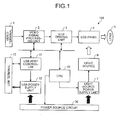
- FIG. 1 is a block diagram illustrating the functional configuration of the projector 100 in this embodiment.
- the projector 100 includes a video terminal 1, a video signal processing unit 2, an LCD driving unit 3, an LCD panel 4, a projection lens 5, a light source 6, a light source power supply unit 7, a USB terminal 10, a USB host controller 11, a USB power supply unit 12, a CPU 20, and a power source circuit 30.
- the video terminal 1 is an input terminal for receiving an input of video data from outside. Examples may include HDMI terminals, S input terminals, and component video terminals.
- the video signal processing unit 2 carries out various image processing or data conversion on input video data.
- the LCD driving unit 3 drives the LCD panel 4 based on the video data processed by the video signal processing unit 2.
- the LCD panel 4 adjusts its angle to direct the light projected from the light source 6 to the lens 5 to form an image.
- the light source power supply unit 7 supplies power to the light source 6.
- the CPU 20 controls the video signal processing unit 2, the LCD driving unit 3, a USB host controller 11, a power source circuit 30, and a light source power supply unit 7 connected on a bus.
- the CPU 20 corresponds to a control unit.
- the projector 100 in this embodiment can project an image input from an external device such as a PC, a DVD player, or a set-top box. These external devices are to be connected to the video terminal 1.
- the video signal processing unit 2 performs contrast adjustment, brightness adjustment, sharpness adjustment, scaling, and superimposition of a menu display, and/or other operations on the video data input from an external device.
- the projector 100 may use any projection methods such as an LCD method or a DLP (Digital Light Processing) method that uses a digital mirror device (DMD).
- DMD digital mirror device
- the LCD method will be described as one example in this embodiment.
- the LCD panel 4 uses three primary colors of red (R), green (G), and blue (B).
- the LCD driving unit 3 converts a video signal processed by the video signal processing unit 2 into an RGB video signal for driving the LCD panel 4.
- the LCD panel 4 is disposed to transmit light emitted from the light source 6 in the projector 100 to form an image based on the input video signal and to project this image through the projection lens 5 to the outside of the projector 100.
- the light intensity of the light source 6 is changed by controlling the light source power supply unit 7 with the CPU 20. The more the light amount of the lamp is, the higher the power consumption of the projector 100 is. For example, when the lamp emits a maximum amount of light, the power consumption of the light source 6 takes up about 80% of that of the entire projector 100.
- the light source power supply unit 7 is supplied with power from the power source circuit 30.
- the CPU 20 controls the power source circuit 30 to start power supply to various parts when it detects a depression of a power button provided to the projector 100.
- the projector 100 can also project video data stored in a USB memory connected to the USB terminal 10.
- the projector 100 has a function of projecting an image directly from a USB device, which is called "USB On-The-Go", and acts as the USB host, so that it can read out video data from the USB memory.
- the USB host controller 11 detects that a USB device is connected to a USB terminal 10, whereupon the USB power supply unit 12 supplies power to the external device connected to the USB terminal 10. That is, the USB terminal 10 and USB power supply unit 12 in this embodiment correspond to a connection unit and a device power supply unit, respectively.
- the USB power supply unit 12 is supplied with power from the power source circuit 30.
- One example of the external device connected to the USB terminal 10 is a receiving apparatus that receives operation of an electronic pen.
- FIG. 2 shows a configuration example of an interactive operation system that uses this receiving apparatus.
- the receiving apparatus 101 connected to the USB terminal 10 of the projector 100 receives information on the position transmitted from the electronic pen 111.
- the projector 100 sends the received positional information to the PC 120.
- the positional information may be transmitted from the projector 100 to the PC 120 either through a wireless communication channel or a USB connection.
- the PC 120 superimposes trajectory data of the pen based on the positional information received from the projector 100 on the signal of the image to be projected, and outputs the signal to the video terminal 1 of the projector 100, which then projects this video signal.
- the system thus achieves an interactive function.
- the projector 100 is a ultra-short-focus projector and the positional information from the electronic pen 111 should preferably be received at a position close to the screen 110. Therefore, the receiving apparatus 101 is supplied with power from the projector 100 via the USB terminal 10.
- FIG. 3 Another example of an external device that can be connected to the projector 100 is a dongle type set-top box connected to an HDMI terminal, which is shown in FIG. 3 .
- the dongle type set-top box 210 having the HDMI terminal is connected to the video terminal 1 of the projector 200, while the USB connector 211 for supplying power to the set-top box is connected to the USB terminal 10 of the projector 200.
- the set-top box 210 receives terrestrial broadcasting or an image distributed via a wireless network and outputs the video signal thereof to the projector 200.
- the projector 200 then projects the image based on the input video signal.
- the external devices shown in FIG. 2 and FIG. 3 are supplied with power from the projectors 100 and 200, respectively, via the USB terminal 10.
- the projector 100 or 200 which is the USB host, supplies power to the connected external device in accordance with the USB standard.
- the power source circuit 30 of the host (here, the projector) has a limited power supply capacity and cannot supply power more than its limit.
- the USB standard allows the host to refuse to supply power to a USB device if there is no surplus of power in the host. That, however, may lead to a case where the USB device cannot be used. Therefore, there is a need for a scheme for saving energy or reducing power consumption in the host when a USB device that demands power is connected. The scheme will be described below.
- the projector 100 also supports a USB hub, and deals with the USB hub connected to the USB terminal 10 of the projector 100 in accordance with the USB standard. Therefore, a plurality of USB devices can be connected to the projector via the USB hub.
- the USB host controller 11 acquires information on the capacity of the external device in the enumeration phase where the external terminal is identified when connected to the projector 100 by USB connection.
- the acquired capacity information also includes the amount of power the external device requires. This amount of power may indicate the maximum amount of power of the external device, or selected one of several levels of power consumption if the external device is capable of adjusting the power consumption stepwise.
- An external device can draw a maximum of 500 mA from the host according to the USB 2.0 specification, and 900 mA according to the USB 3.0 specification.
- As the USB standard supplies a voltage of +5 V a USB 2.0 device can consume a maximum of 2.5 W power, and a USB 3.0 device can consume a maximum of 4.5 W power.
- the projector 100 consumes the maximum proportion of power in the light source 6, as mentioned above. Although it depends on the type of the projector, the light source 6 can use up to 80% of power of the entire projector. If the brightness of the projector is about 2500 lumens, the entire projector can consume about 250 W power. In this case, about 200 W would be consumed by the light source 6.
- the CPU 20 allocates about 2.5 to 4.5 W out of 200 W that is consumed by the light source 6, to supply power to the external device.
- the lamp brightness will lower about 1.25 to 2.25% by the reduced amount of power, which is hardly perceptible to the eye, and therefore has hardly any impact on the quality of projected image.
- the projector 100 which is the host, detects in the enumeration phase that an external device that demands power is connected, and reduces the amount of power supplied to the light source 6 by the amount of power to be consumed by the external device. This control is performed by the CPU 20 to the light source power supply unit 7.
- FIG. 4 shows the flow of this process. As shown in FIG. 4 , first, the USB host controller 11 detects that an external device is connected to the USB terminal 10 (step S101).
- the USB host controller 11 acquires information on the maximum amount of power to be consumed from the connected external device (step S102). This information on the maximum amount of power consumption is stored in the external device in advance in a format supported by the USB standard so that it is available to the host via USB.
- the CPU 20 then instructs the light source power supply unit 7 to reduce the power of the light source by an amount of power corresponding to the maximum power consumption of the external device (step S103).
- the projector 100 of this embodiment acquires information on the maximum amount of power to be consumed by the connected external device when an external device that draws power through the USB terminal 10 is connected, and reduces the power to the light source 6 by the amount of the maximum power consumption of the external device. Since a large amount of power is supplied to the light source 6, the reduction in power by the amount necessary for driving the external device only slightly affects the brightness in practice. Thus the external device can be supplied with power appropriately while suppressing reduction of the quality of the image or the performance of the projector 100.
- the second embodiment differs from the first embodiment in that the amount of power supplied to the external device is compensated for by further reducing the power consumption of the light source 6. More specifically, the video signal processing unit 2 performs an operation to vary the brightness level of the video data input from the video terminal 1.
- the brightness level may be varied by, for example, gamma correction carried out in the video signal processing unit 2.
- Gamma correction defines the brightness level of video data to be output relative to the brightness level (gradation) of the input original video data.
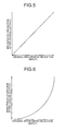
- FIG. 5 shows a case where the brightness level of input video data and that of output video data are equivalent and no correction is performed.
- the brightness level of the output video data will be reduced relative to the brightness level of the input video data, as shown in FIG. 6 .
- the power consumption required for the light source 6 will also decrease.
- step S101 to S103 in FIG. 7 are the same as those shown in FIG. 4 and will not be described again.
- the video signal processing unit 2 performs a gamma correction process that reduces the brightness, on the input video data (step S201). By reducing the brightness, the power consumption of the light source 6 can further be reduced.
- This gamma correction process may be performed in accordance with a predetermined standard instead of being carried out to all the input video data.
- the gamma correction process may be performed when the amount of power for the light source 6 reduced by the power supply to the external device becomes equal to or smaller than a predetermined threshold, i.e., when the power consumption of the external device becomes equal to or larger than a predetermined threshold.
- the threshold may be 500 mA, for example, which is the standard power for USB devices. Since reducing the light amount of the light source 6 may apparently lower overall brightness, the brightness level is adjusted by gamma correction only when the power supply to the light source 6 is equal to or smaller than the predetermined threshold, thereby to save energy.
- FIG. 8 shows the flow of the process in this case.
- step S202 whether or not the acquired data of the power consumption of the external device indicates that the power consumption is equal to or larger than a predetermined threshold is determined. If the power consumption is equal to or larger than the predetermined threshold (YES at step S202), the gamma correction process is performed.
- the decision may be made based on whether or not the sum of the respective power consumptions of the connected external devices, and not the individual power consumption, is equal to or larger than the predetermined threshold.
- FIG. 9 is a diagram illustrating one example of the shape of the projector 100.
- the drawing shows a perspective view of the front side of the image projection apparatus.
- the embodiment provides the effect of reducing power consumption while suppressing reduction of the quality of projected image.
Landscapes
- Engineering & Computer Science (AREA)
- Multimedia (AREA)
- Signal Processing (AREA)
- General Engineering & Computer Science (AREA)
- Theoretical Computer Science (AREA)
- Computer Hardware Design (AREA)
- Physics & Mathematics (AREA)
- General Physics & Mathematics (AREA)
- Transforming Electric Information Into Light Information (AREA)
- Projection Apparatus (AREA)
- Control Of Indicators Other Than Cathode Ray Tubes (AREA)
Abstract
An image projection apparatus (100, 200) includes: a connection unit (10) to which an external device (101, 210) is to be connected; a light source power supply unit (7) that supplies power to a light source (6); a device power supply unit (12) that supplies drive power via the connection unit (10) to the external device (101, 210); a power acquisition unit (11) that acquires an amount of power to be consumed by the external device (101, 210) when the external device (101, 210) is connected; and a control unit (20) that controls the light source power supply unit (7) to supply, to the light source (6), an amount of power reduced by the amount of power to be consumed by the external device (101, 210) when the external device (101, 210) is connected.
Description
- The present application claims priority to and incorporates by reference the entire contents of Japanese Patent Application No.
2013-004973 - The present invention relates to an image projection apparatus and a power control method.
- Some image projection apparatuses such as projectors of recent years are configured to supply power to a connected peripheral device. One example of such peripheral device is a receiving apparatus of an electronic pen or the like, which acquires information on the position on a screen transmitted from the electronic pen when a letter or a figure is drawn by a user with the electronic pen on an image or picture projected on the screen. Such a receiving apparatus is connected to the projector with a USB cable, for example, and it is supplied with power via the USB. Positional information of the electronic pen received by the receiving apparatus is transmitted to a PC that is connected to the projector, where data input from the electronic pen is combined with image data that is to be projected, and the combined image data is projected from the projector. Another example of a device connected to the projector is a dongle type set-top box connected to an HDMI terminal.
- In a case where such a device receives power from a projector, the power that the projector can supply to the device is limited. Japanese Laid-open Patent Publication No.
2009-086223 2007-305062 - These conventional techniques achieve energy saving by reducing the quality of projected image data or the performance.
- In view of the circumstance described above, there is a need to realize an image projection apparatus that can reduce power consumption while suppressing reduction of the quality of projected images when there is an external device connected to the image projection apparatus.
- It is an object of the present invention to at least partially solve the problems in the conventional technology.
- The above and other objects, features, advantages and technical and industrial significance of this invention will be better understood by reading the following detailed description of presently preferred embodiments of the invention, when considered in connection with the accompanying drawings.
-
-
FIG. 1 is a block diagram illustrating the functional configuration of the image projection apparatus in a first embodiment. -
FIG. 2 is a diagram illustrating a system configuration example in which the image projection apparatus of the first embodiment is connected to an external device. -
FIG. 3 is a diagram illustrating a system configuration example in which the image projection apparatus of the first embodiment is connected to an external device. -
FIG. 4 is a flowchart showing the flow of the process steps for determining an amount of power in the image projection apparatus of the first embodiment. -
FIG. 5 is a graph showing the relationship between the gradation of input image data and that of output image data of the image projection apparatus of a second embodiment. -
FIG. 6 is a graph showing the relationship between the gradation of input image data and that of output image data of the image projection apparatus of the second embodiment. -
FIG. 7 is a flowchart showing the flow of the process steps for determining an amount of power in the image projection apparatus of the second embodiment. -
FIG. 8 is a flowchart showing the flow of the process steps for determining an amount of power in another example of image projection apparatus of the second embodiment. -
FIG. 9 is a perspective view of the front side of the image projection apparatus in which information processing devices of various embodiments are embodied. - Hereinafter, an image projection apparatus of the present invention embodied as a
projector 100 will be described.FIG. 1 is a block diagram illustrating the functional configuration of theprojector 100 in this embodiment. Theprojector 100 includes a video terminal 1, a videosignal processing unit 2, anLCD driving unit 3, anLCD panel 4, aprojection lens 5, a light source 6, a light sourcepower supply unit 7, aUSB terminal 10, aUSB host controller 11, a USBpower supply unit 12, aCPU 20, and apower source circuit 30. - The video terminal 1 is an input terminal for receiving an input of video data from outside. Examples may include HDMI terminals, S input terminals, and component video terminals. The video
signal processing unit 2 carries out various image processing or data conversion on input video data. TheLCD driving unit 3 drives theLCD panel 4 based on the video data processed by the videosignal processing unit 2. TheLCD panel 4 adjusts its angle to direct the light projected from the light source 6 to thelens 5 to form an image. The light sourcepower supply unit 7 supplies power to the light source 6. - The
CPU 20 controls the videosignal processing unit 2, theLCD driving unit 3, aUSB host controller 11, apower source circuit 30, and a light sourcepower supply unit 7 connected on a bus. TheCPU 20 corresponds to a control unit. - The
projector 100 in this embodiment can project an image input from an external device such as a PC, a DVD player, or a set-top box. These external devices are to be connected to the video terminal 1. The videosignal processing unit 2 performs contrast adjustment, brightness adjustment, sharpness adjustment, scaling, and superimposition of a menu display, and/or other operations on the video data input from an external device. Theprojector 100 may use any projection methods such as an LCD method or a DLP (Digital Light Processing) method that uses a digital mirror device (DMD). The LCD method will be described as one example in this embodiment. TheLCD panel 4 uses three primary colors of red (R), green (G), and blue (B). TheLCD driving unit 3 converts a video signal processed by the videosignal processing unit 2 into an RGB video signal for driving theLCD panel 4. TheLCD panel 4 is disposed to transmit light emitted from the light source 6 in theprojector 100 to form an image based on the input video signal and to project this image through theprojection lens 5 to the outside of theprojector 100. The light intensity of the light source 6 is changed by controlling the light sourcepower supply unit 7 with theCPU 20. The more the light amount of the lamp is, the higher the power consumption of theprojector 100 is. For example, when the lamp emits a maximum amount of light, the power consumption of the light source 6 takes up about 80% of that of theentire projector 100. The light sourcepower supply unit 7 is supplied with power from thepower source circuit 30. TheCPU 20 controls thepower source circuit 30 to start power supply to various parts when it detects a depression of a power button provided to theprojector 100. - The
projector 100 can also project video data stored in a USB memory connected to theUSB terminal 10. Theprojector 100 has a function of projecting an image directly from a USB device, which is called "USB On-The-Go", and acts as the USB host, so that it can read out video data from the USB memory. TheUSB host controller 11 detects that a USB device is connected to aUSB terminal 10, whereupon the USBpower supply unit 12 supplies power to the external device connected to theUSB terminal 10. That is, theUSB terminal 10 and USBpower supply unit 12 in this embodiment correspond to a connection unit and a device power supply unit, respectively. The USBpower supply unit 12 is supplied with power from thepower source circuit 30. One example of the external device connected to theUSB terminal 10 is a receiving apparatus that receives operation of an electronic pen.FIG. 2 shows a configuration example of an interactive operation system that uses this receiving apparatus. - As shown in
FIG. 2 , when a letter or a figure is drawn on thescreen 110 with theelectronic pen 111, thereceiving apparatus 101 connected to theUSB terminal 10 of theprojector 100 receives information on the position transmitted from theelectronic pen 111. Theprojector 100 sends the received positional information to the PC 120. The positional information may be transmitted from theprojector 100 to the PC 120 either through a wireless communication channel or a USB connection. ThePC 120 superimposes trajectory data of the pen based on the positional information received from theprojector 100 on the signal of the image to be projected, and outputs the signal to the video terminal 1 of theprojector 100, which then projects this video signal. The system thus achieves an interactive function. - In this configuration example, the
projector 100 is a ultra-short-focus projector and the positional information from theelectronic pen 111 should preferably be received at a position close to thescreen 110. Therefore, the receivingapparatus 101 is supplied with power from theprojector 100 via theUSB terminal 10. - Another example of an external device that can be connected to the
projector 100 is a dongle type set-top box connected to an HDMI terminal, which is shown inFIG. 3 . As shown inFIG. 3 , the dongle type set-top box 210 having the HDMI terminal is connected to the video terminal 1 of theprojector 200, while theUSB connector 211 for supplying power to the set-top box is connected to theUSB terminal 10 of theprojector 200. The set-top box 210 receives terrestrial broadcasting or an image distributed via a wireless network and outputs the video signal thereof to theprojector 200. Theprojector 200 then projects the image based on the input video signal. - The external devices shown in
FIG. 2 and FIG. 3 are supplied with power from theprojectors USB terminal 10. Theprojector power source circuit 30 of the host (here, the projector) has a limited power supply capacity and cannot supply power more than its limit. The USB standard allows the host to refuse to supply power to a USB device if there is no surplus of power in the host. That, however, may lead to a case where the USB device cannot be used. Therefore, there is a need for a scheme for saving energy or reducing power consumption in the host when a USB device that demands power is connected. The scheme will be described below. Theprojector 100 also supports a USB hub, and deals with the USB hub connected to theUSB terminal 10 of theprojector 100 in accordance with the USB standard. Therefore, a plurality of USB devices can be connected to the projector via the USB hub. - The USB host controller 11 (power acquisition unit) acquires information on the capacity of the external device in the enumeration phase where the external terminal is identified when connected to the
projector 100 by USB connection. The acquired capacity information also includes the amount of power the external device requires. This amount of power may indicate the maximum amount of power of the external device, or selected one of several levels of power consumption if the external device is capable of adjusting the power consumption stepwise. An external device can draw a maximum of 500 mA from the host according to the USB 2.0 specification, and 900 mA according to the USB 3.0 specification. As the USB standard supplies a voltage of +5 V, a USB 2.0 device can consume a maximum of 2.5 W power, and a USB 3.0 device can consume a maximum of 4.5 W power. Theprojector 100 consumes the maximum proportion of power in the light source 6, as mentioned above. Although it depends on the type of the projector, the light source 6 can use up to 80% of power of the entire projector. If the brightness of the projector is about 2500 lumens, the entire projector can consume about 250 W power. In this case, about 200 W would be consumed by the light source 6. TheCPU 20 allocates about 2.5 to 4.5 W out of 200 W that is consumed by the light source 6, to supply power to the external device. The lamp brightness will lower about 1.25 to 2.25% by the reduced amount of power, which is hardly perceptible to the eye, and therefore has hardly any impact on the quality of projected image. - The higher the projector's maximum brightness (e.g., 5000 lumens) is, the smaller the ratio of the brightness reduction due to the power supply to the external device will be, and hence its impact is more negligible. The
projector 100, which is the host, detects in the enumeration phase that an external device that demands power is connected, and reduces the amount of power supplied to the light source 6 by the amount of power to be consumed by the external device. This control is performed by theCPU 20 to the light sourcepower supply unit 7.FIG. 4 shows the flow of this process. As shown inFIG. 4 , first, theUSB host controller 11 detects that an external device is connected to the USB terminal 10 (step S101). TheUSB host controller 11 then acquires information on the maximum amount of power to be consumed from the connected external device (step S102). This information on the maximum amount of power consumption is stored in the external device in advance in a format supported by the USB standard so that it is available to the host via USB. TheCPU 20 then instructs the light sourcepower supply unit 7 to reduce the power of the light source by an amount of power corresponding to the maximum power consumption of the external device (step S103). - The
projector 100 of this embodiment, as described above, acquires information on the maximum amount of power to be consumed by the connected external device when an external device that draws power through theUSB terminal 10 is connected, and reduces the power to the light source 6 by the amount of the maximum power consumption of the external device. Since a large amount of power is supplied to the light source 6, the reduction in power by the amount necessary for driving the external device only slightly affects the brightness in practice. Thus the external device can be supplied with power appropriately while suppressing reduction of the quality of the image or the performance of theprojector 100. - The second embodiment differs from the first embodiment in that the amount of power supplied to the external device is compensated for by further reducing the power consumption of the light source 6. More specifically, the video
signal processing unit 2 performs an operation to vary the brightness level of the video data input from the video terminal 1. The brightness level may be varied by, for example, gamma correction carried out in the videosignal processing unit 2. Gamma correction defines the brightness level of video data to be output relative to the brightness level (gradation) of the input original video data.FIG. 5 shows a case where the brightness level of input video data and that of output video data are equivalent and no correction is performed. With gamma correction to the input video data, the brightness level of the output video data will be reduced relative to the brightness level of the input video data, as shown inFIG. 6 . When the brightness level of the output video data is reduced, the power consumption required for the light source 6 will also decrease. - The flow of the process will be described in detail with reference to
FIG. 7 . Process steps S101 to S103 inFIG. 7 are the same as those shown inFIG. 4 and will not be described again. As shown inFIG. 7 , after the process of step S103, the videosignal processing unit 2 performs a gamma correction process that reduces the brightness, on the input video data (step S201). By reducing the brightness, the power consumption of the light source 6 can further be reduced. - This gamma correction process may be performed in accordance with a predetermined standard instead of being carried out to all the input video data. For example, the gamma correction process may be performed when the amount of power for the light source 6 reduced by the power supply to the external device becomes equal to or smaller than a predetermined threshold, i.e., when the power consumption of the external device becomes equal to or larger than a predetermined threshold. The threshold may be 500 mA, for example, which is the standard power for USB devices. Since reducing the light amount of the light source 6 may apparently lower overall brightness, the brightness level is adjusted by gamma correction only when the power supply to the light source 6 is equal to or smaller than the predetermined threshold, thereby to save energy.
FIG. 8 shows the flow of the process in this case. The process steps inFIG. 8 that are the same as those ofFIG. 4 andFIG. 7 are given the same reference numerals and will not be described again. As shown inFIG. 8 , in step S202 whether or not the acquired data of the power consumption of the external device indicates that the power consumption is equal to or larger than a predetermined threshold is determined. If the power consumption is equal to or larger than the predetermined threshold (YES at step S202), the gamma correction process is performed. - At the determination in
FIG. 8 , if a plurality of external devices are connected to theUSB terminal 10, the decision may be made based on whether or not the sum of the respective power consumptions of the connected external devices, and not the individual power consumption, is equal to or larger than the predetermined threshold. -
FIG. 9 is a diagram illustrating one example of the shape of theprojector 100. The drawing shows a perspective view of the front side of the image projection apparatus. - While power is supplied via the
USB terminal 10 in the embodiments described above, power can be supplied via another connection unit. - The embodiment provides the effect of reducing power consumption while suppressing reduction of the quality of projected image.
- Although the invention has been described with respect to specific embodiments for a complete and clear disclosure, the appended claims are not to be thus limited but are to be construed as embodying all modifications and alternative constructions that may occur to one skilled in the art that fairly fall within the basic teaching herein set forth.
Claims (5)
- An image projection apparatus (100, 200) comprising:a connection unit (10) to which an external device (101, 210) is to be connected;a light source power supply unit (7) that supplies power to a light source (6);a device power supply unit (12) that supplies drive power via the connection unit (10) to the external device (101, 210);a power acquisition unit (11) that acquires an amount of power to be consumed by the external device (101, 210) when the external device (101, 210) is connected; anda control unit (20) that controls the light source power supply unit (7) to supply, to the light source (6), an amount of power reduced by the amount of power to be consumed by the external device (101, 210) when the external device (101, 210) is connected.
- The image projection apparatus (100, 200) according to claim 1, further comprising a video signal processing unit (2) that performs, on input video data, image processing that reduces brightness, and wherein
the control unit (20) controls the video signal processing unit (2) to perform, on the input video data, the image processing that reduces brightness when the external device (101, 210) is connected. - The image projection apparatus (100, 200) according to claim 2, wherein the control unit (20) controls the video signal processing unit (2) to perform, on the input video data, the image processing that reduces brightness when the external device (101, 210) is connected and when the acquired amount of power consumed by the external device (101, 210) is equal to or larger than a predetermined threshold.
- The image projection apparatus (100, 200) according to claim 3, wherein
a plurality of the external devices (101, 210) are connected to the connection unit (10), and
the control unit (20) controls the video signal processing unit (2) to perform, on the input video data, the image processing that reduces brightness when the external devices (101, 210) are connected and when a sum of the respectively-acquired amounts of power consumed by the external devices (101, 210) is equal to or larger than a predetermined threshold. - A power control method of an image projection apparatus (100, 200), the image projection apparatus (100, 200) including:a connection unit (10) to which an external device (101, 210) is to be connected;a light source power supply unit (7) that supplies power to a light source (6);a device power supply unit (12) that supplies drive power via the connection unit (10) to the external device (101, 210);a power acquisition unit (11) that acquires an amount of power to be consumed by the external device (101, 210) when the external device (101, 210) is connected; anda control unit (20) that controls power supplied to the light source (6), the power control method comprising:a detecting step of detecting that the external device (101, 210) is connected; anda controlling step of controlling the light source power supply unit (7) to supply, to the light source (6), an amount of power reduced by the amount of power to be consumed by the external device (101, 210) when it is detected that the external device (101, 210) is connected.
Applications Claiming Priority (1)
| Application Number | Priority Date | Filing Date | Title |
|---|---|---|---|
| JP2013004973 | 2013-01-15 |
Publications (1)
| Publication Number | Publication Date |
|---|---|
| EP2755380A1 true EP2755380A1 (en) | 2014-07-16 |
Family
ID=50028763
Family Applications (1)
| Application Number | Title | Priority Date | Filing Date |
|---|---|---|---|
| EP20140151102 Withdrawn EP2755380A1 (en) | 2013-01-15 | 2014-01-14 | Image projection apparatus and power control method |
Country Status (1)
| Country | Link |
|---|---|
| EP (1) | EP2755380A1 (en) |
Cited By (1)
| Publication number | Priority date | Publication date | Assignee | Title |
|---|---|---|---|---|
| CN114442791A (en) * | 2020-11-05 | 2022-05-06 | 深圳Tcl新技术有限公司 | Power adjustment method, intelligent terminal and storage medium |
Citations (11)
| Publication number | Priority date | Publication date | Assignee | Title |
|---|---|---|---|---|
| EP1659478A1 (en) * | 2003-08-28 | 2006-05-24 | Fujitsu Limited | Host apparatus, device, and communication system control method |
| US20070250193A1 (en) * | 2006-04-20 | 2007-10-25 | Sandisk Il Ltd. | Dongle-based multimedia player |
| JP2007305062A (en) | 2006-05-15 | 2007-11-22 | Seiko Epson Corp | Electronic control device, control method thereof and program thereof |
| EP2015162A1 (en) * | 2007-07-12 | 2009-01-14 | Research In Motion Limited | System and method for portable power source management |
| JP2009086223A (en) | 2007-09-28 | 2009-04-23 | Nikon Corp | Electronic equipment with projection function |
| US20090256973A1 (en) * | 2008-03-31 | 2009-10-15 | Cristiano Bazzani | Reducing power dissipation in portable LCOS/LCD/DLP portable projection systems |
| EP2131350A1 (en) * | 2007-03-26 | 2009-12-09 | NEC Corporation | Portable phone terminal, image display controlling method, program thereof, and program recording medium |
| EP2312569A2 (en) * | 2009-10-16 | 2011-04-20 | Samsung Electronics Co., Ltd. | Method and apparatus for controlling power consumption of light source in mobile projector |
| US20110264933A1 (en) * | 2010-04-23 | 2011-10-27 | Lawrence David Forsythe | Method and apparatus for optimal allocation of operating power across multiple power domains of a handheld device |
| US20120098851A1 (en) * | 2009-06-26 | 2012-04-26 | Kyocera Corporation | Mobile electronic device |
| US20120246458A1 (en) * | 2011-03-25 | 2012-09-27 | Cisco Technology, Inc. | Power optimization on a thin client device |
-
2014
- 2014-01-14 EP EP20140151102 patent/EP2755380A1/en not_active Withdrawn
Patent Citations (11)
| Publication number | Priority date | Publication date | Assignee | Title |
|---|---|---|---|---|
| EP1659478A1 (en) * | 2003-08-28 | 2006-05-24 | Fujitsu Limited | Host apparatus, device, and communication system control method |
| US20070250193A1 (en) * | 2006-04-20 | 2007-10-25 | Sandisk Il Ltd. | Dongle-based multimedia player |
| JP2007305062A (en) | 2006-05-15 | 2007-11-22 | Seiko Epson Corp | Electronic control device, control method thereof and program thereof |
| EP2131350A1 (en) * | 2007-03-26 | 2009-12-09 | NEC Corporation | Portable phone terminal, image display controlling method, program thereof, and program recording medium |
| EP2015162A1 (en) * | 2007-07-12 | 2009-01-14 | Research In Motion Limited | System and method for portable power source management |
| JP2009086223A (en) | 2007-09-28 | 2009-04-23 | Nikon Corp | Electronic equipment with projection function |
| US20090256973A1 (en) * | 2008-03-31 | 2009-10-15 | Cristiano Bazzani | Reducing power dissipation in portable LCOS/LCD/DLP portable projection systems |
| US20120098851A1 (en) * | 2009-06-26 | 2012-04-26 | Kyocera Corporation | Mobile electronic device |
| EP2312569A2 (en) * | 2009-10-16 | 2011-04-20 | Samsung Electronics Co., Ltd. | Method and apparatus for controlling power consumption of light source in mobile projector |
| US20110264933A1 (en) * | 2010-04-23 | 2011-10-27 | Lawrence David Forsythe | Method and apparatus for optimal allocation of operating power across multiple power domains of a handheld device |
| US20120246458A1 (en) * | 2011-03-25 | 2012-09-27 | Cisco Technology, Inc. | Power optimization on a thin client device |
Cited By (2)
| Publication number | Priority date | Publication date | Assignee | Title |
|---|---|---|---|---|
| CN114442791A (en) * | 2020-11-05 | 2022-05-06 | 深圳Tcl新技术有限公司 | Power adjustment method, intelligent terminal and storage medium |
| CN114442791B (en) * | 2020-11-05 | 2024-01-19 | 深圳Tcl新技术有限公司 | A power adjustment method, intelligent terminal and storage medium |
Similar Documents
| Publication | Publication Date | Title |
|---|---|---|
| CN107038982B (en) | Projection device and control method thereof | |
| US8780143B2 (en) | Display method and apparatus for controlling brightness of projector light source | |
| US10242607B2 (en) | Display system, display apparatus, method of controlling display apparatus, and program | |
| US20170061894A1 (en) | Image display apparatus | |
| US20100171933A1 (en) | Method for compensating for color loss of image in image projector and apparatus thereof | |
| KR102554598B1 (en) | Display device and operating local dimming control method thereof | |
| JP6883254B2 (en) | Display device, display method and display system | |
| US20110043704A1 (en) | Image display device, image display method, and image processing device | |
| US10802383B2 (en) | Projector and method for controlling projector | |
| US20110113272A1 (en) | Projector and power control method thereof | |
| WO2023246211A1 (en) | Laser projection apparatus and projection image display method | |
| US8654058B2 (en) | Apparatus and method for enhancing image contrast | |
| US11637997B2 (en) | Projection apparatus and control method | |
| US9813683B2 (en) | Light source control apparatus, image display apparatus and light source control method | |
| US9300905B2 (en) | Projector, projector control method, and recording medium storing projector control program | |
| CN111866307B (en) | Display device, control method of display device, and storage medium | |
| US11044435B2 (en) | Driver circuit and projector including voltage conversion units at primary side | |
| JP2019128590A (en) | Image projection device | |
| KR20230171722A (en) | Display apparatus and control method thereof | |
| JP2013130744A (en) | Image display device | |
| US8896234B2 (en) | Power supply apparatus and display apparatus including the same | |
| JP2014137595A (en) | Image projection device, and power control method | |
| KR102663510B1 (en) | Electronic apparatus and the control method thereof | |
| JP5407176B2 (en) | Projection system | |
| JP5387752B2 (en) | Projection apparatus, projection method, and program |
Legal Events
| Date | Code | Title | Description |
|---|---|---|---|
| PUAI | Public reference made under article 153(3) epc to a published international application that has entered the european phase |
Free format text: ORIGINAL CODE: 0009012 |
|
| 17P | Request for examination filed |
Effective date: 20140115 |
|
| AK | Designated contracting states |
Kind code of ref document: A1 Designated state(s): AL AT BE BG CH CY CZ DE DK EE ES FI FR GB GR HR HU IE IS IT LI LT LU LV MC MK MT NL NO PL PT RO RS SE SI SK SM TR |
|
| AX | Request for extension of the european patent |
Extension state: BA ME |
|
| 17Q | First examination report despatched |
Effective date: 20160805 |
|
| STAA | Information on the status of an ep patent application or granted ep patent |
Free format text: STATUS: THE APPLICATION IS DEEMED TO BE WITHDRAWN |
|
| 18D | Application deemed to be withdrawn |
Effective date: 20161216 |