EP2755209A1 - Sample-containing cell for x-ray microscope and method for observing x-ray microscopic image - Google Patents
Sample-containing cell for x-ray microscope and method for observing x-ray microscopic image Download PDFInfo
- Publication number
- EP2755209A1 EP2755209A1 EP20120830348 EP12830348A EP2755209A1 EP 2755209 A1 EP2755209 A1 EP 2755209A1 EP 20120830348 EP20120830348 EP 20120830348 EP 12830348 A EP12830348 A EP 12830348A EP 2755209 A1 EP2755209 A1 EP 2755209A1
- Authority
- EP
- European Patent Office
- Prior art keywords
- ray
- sample
- containing cell
- film
- ray transmission
- Prior art date
- Legal status (The legal status is an assumption and is not a legal conclusion. Google has not performed a legal analysis and makes no representation as to the accuracy of the status listed.)
- Granted
Links
Images



Classifications
-
- G—PHYSICS
- G01—MEASURING; TESTING
- G01N—INVESTIGATING OR ANALYSING MATERIALS BY DETERMINING THEIR CHEMICAL OR PHYSICAL PROPERTIES
- G01N23/00—Investigating or analysing materials by the use of wave or particle radiation, e.g. X-rays or neutrons, not covered by groups G01N3/00 – G01N17/00, G01N21/00 or G01N22/00
- G01N23/02—Investigating or analysing materials by the use of wave or particle radiation, e.g. X-rays or neutrons, not covered by groups G01N3/00 – G01N17/00, G01N21/00 or G01N22/00 by transmitting the radiation through the material
- G01N23/04—Investigating or analysing materials by the use of wave or particle radiation, e.g. X-rays or neutrons, not covered by groups G01N3/00 – G01N17/00, G01N21/00 or G01N22/00 by transmitting the radiation through the material and forming images of the material
-
- G—PHYSICS
- G21—NUCLEAR PHYSICS; NUCLEAR ENGINEERING
- G21K—HANDLING OF PARTICLES OR IONISING RADIATION NOT OTHERWISE PROVIDED FOR; IRRADIATION DEVICES; GAMMA RAY OR X-RAY MICROSCOPES
- G21K5/00—Irradiation devices
- G21K5/08—Holders for targets or for other objects to be irradiated
-
- G—PHYSICS
- G21—NUCLEAR PHYSICS; NUCLEAR ENGINEERING
- G21K—HANDLING OF PARTICLES OR IONISING RADIATION NOT OTHERWISE PROVIDED FOR; IRRADIATION DEVICES; GAMMA RAY OR X-RAY MICROSCOPES
- G21K7/00—Gamma- or X-ray microscopes
-
- G—PHYSICS
- G01—MEASURING; TESTING
- G01N—INVESTIGATING OR ANALYSING MATERIALS BY DETERMINING THEIR CHEMICAL OR PHYSICAL PROPERTIES
- G01N2223/00—Investigating materials by wave or particle radiation
- G01N2223/30—Accessories, mechanical or electrical features
- G01N2223/309—Accessories, mechanical or electrical features support of sample holder
-
- G—PHYSICS
- G01—MEASURING; TESTING
- G01N—INVESTIGATING OR ANALYSING MATERIALS BY DETERMINING THEIR CHEMICAL OR PHYSICAL PROPERTIES
- G01N2223/00—Investigating materials by wave or particle radiation
- G01N2223/60—Specific applications or type of materials
- G01N2223/612—Specific applications or type of materials biological material
Definitions
- the present invention relates to a technology for observing an X-ray microscopic image and particularly relates to a technology suitable for high-resolution X-ray microscope observation of a biological sample in a solution.
- X-ray microscopes can perform high-resolution observation of a sample in a solution, giving a useful technique in the case where the observation target sample is a biological sample particularly.
- X-rays in a wavelength range of 2.3 to 4.4 nm corresponding to an energy range of 284 to 540 eV
- water window soft X-rays
- differences in absorption coefficient between the constituent substances of the living body are large and the relevant X-rays, while transmitted without being absorbed by water, are liable to be absorbed by carbon and nitrogen, this leading to characteristics in which proteins and the like hardly allow the relevant X-rays to be transmitted.
- X-ray microscope observation using the soft X-rays is suitable for observing a biological sample.
- the soft X-rays in the wavelength region of "water window” have enable an observation target object containing moisture (biological sample or sample in a solution) to be observed as it is, and in addition, enables observation in higher resolution than in the optical microscope observation because of the shorter wavelength than that of the visible light. Such reasons are promoting development of the microscope utilizing the X-rays in the "water window” wavelength region (soft X-ray microscope).
- soft X-rays in a wavelength region of "carbon window” (5.0 to 4.5 nm) showing less absorption by carbon and soft X-rays in a region of a further shorter wavelength (0.6 to 2.3 nm) are also effective for observing a biological sample.
- X-ray microscopes are categorized mainly into a scheme of irradiating the sample with an X-ray beam thinly focused using a light collecting system such as a zone plate (light collecting scheme) and a scheme of irradiating the sample with an X-ray beam from a point light source (point light source scheme).
- a light collecting system such as a zone plate (light collecting scheme)
- a scheme of irradiating the sample with an X-ray beam from a point light source point light source scheme
- the X-ray microscopes in the light collecting scheme are categorized into ones of irradiating transmission type and ones of scanning transmission type.
- the resolution depends on processing precision of the zone plate and the like and its theoretical limit is predicted to be approximately 10 to 15 nm.
- the X-ray microscopes in the point light source scheme are categorized into a scheme of generating X-rays with a laser and a scheme of generating X-rays by means of irradiation with a charged particle beam such as an electron beam.
- a scheme of generating X-rays by means of irradiation with a charged particle beam including a technique that an electron beam is allowed to incident on and through the surface of a sample supporting film to generate the X-rays in the sample supporting film and samples adhering to the rear face of the sample supporting film is irradiated with the X-rays
- Patent Literature 1 Japanese Patent Laid-Open No. 8-43600
- Patent Literature 2 Japanese Patent No. 4565168
- Patent Literature 3 Japanese Patent Laid-Open No. 2-138856 .
- a silicon nitride film As a sample supporting member (supporting film) used for such soft X-ray microscope observation, a silicon nitride film has been widely used. Since the silicon nitride film has excellent pressure resistance, it has been thought that even when the relevant silicon nitride film is provided in a window part of a sample-containing cell inside which is under atmospheric pressure, the usage of the sample-containing cell in the microscope apparatus inside which is under a vacuum suffers no difficulty at all. For example, according to the invention disclosed in Japanese Patent Laid-Open No.
- Patent Literature 4 a sample cell in which two silicon nitride films are arranged opposite to each other with a predetermined interval is used, a recess for storing a sample solution is provided in the periphery of an X-ray transmission window, observation samples along with a solution are sealed between the silicon nitride films to be closed, and thus, X-ray microscope observation is performed.
- the silicon nitride film has excellent pressure resistance, it has been thought that the sample-containing cell using such a film as a sample supporting member (supporting film) practically suffers no difficulty at all in the usage inside the X-ray microscope apparatus. Nevertheless, the inventors consider that the sample-containing cell with the conventional configuration still leaves room for further improvement.
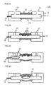
- FIGS 1A to C are diagrams for explaining a problem arising in using the sample-containing cell with the conventional configuration in an X-ray microscope.
- a sample-containing cell 100 includes a container part 10 having a cavity part 11 for containing observation samples along with a solution. Hole parts 12 through which a sample solution is introduced for filling are provided in the container part 10.
- an X-ray emission film 13 that receives irradiation with charged particles and emits soft X-rays and a first X-ray transmission film 14a that transmits the soft X-rays and is capable of maintaining airtightness in the cavity part 11 are provided in this order in the upper portion of the figure.
- a second X-ray transmission film 14b that transmits the soft X-rays from the X-ray emission film 13 and is capable of maintaining airtightness in the cavity part 11 is provided in the lower portion of the figure.
- sample-containing cell 100 When such a sample-containing cell 100 is filled with a sample solution 15, observation samples 16 in the sample solution are held due to absorption or the like on the X-ray transmission film (on the rear face of the first X-ray transmission film 14a in the example illustrated in Figure 1B ).
- the X-ray transmission film also functions as a sample supporting film.
- the hole parts 12 After the filling with the sample solution, the hole parts 12 are closed with sealing members 17 and the sample-containing cell 100 is set inside the X-ray microscope.
- the inside of the mirror body is configured to be under a vacuum.
- the thicknesses of the X-ray emission film 13 and the X-ray transmission films 14a and 14b are small generally with a sub-micrometer level (for example, approximately 0.05 to 0.1 ⁇ m). Due to the pressure difference, the X-ray emission film 13 and the X-ray transmission films 14a and 14b are bent to be convex outward ( Figure 1 C) .
- An extent of the bending depends on the thicknesses and materials of the X-ray emission film 13 and the X-ray transmission films 14a and 14b and the gap do being 5 ⁇ m under atmospheric pressure can sometimes become a gap d being 20 ⁇ m under a vacuum.
- the cause for such a phenomenon including that air bubbles generated due to the reduced pressure at any location in the sample solution 15, for example, lead to substantial increase in volume of the sample solution 15.
- the sample solution 15 for example, is allowed to be at a reduced pressure for degassing in advance before the sample-containing cell 100 is set inside the X-ray microscope as an effective process. Nevertheless, such a process possibly causes exceeding evacuation in pressure inside the sample-containing cell 100.
- the observation samples 16 are relatively vulnerable ones such as living body cells, their partial breakage or the like caused by this can disadvantageously affect the morphological observation of those as a result.
- the present invention is devised in view of such problems regarding the sample-containing cell with the conventional configuration as mentioned above and an object is to provide a sample-containing cell contributing to high-resolution X-ray microscope observation of a biological sample in a solution particularly.
- a sample-containing cell which is a sample-containing cell for an X-ray microscope, the sample-containing cell used in performing X-ray microscope observation in a vacuum mirror body, the sample-containing cell including: a cavity part for containing a sample solution inside; a charged particle incident window provided on one face of the sample-containing cell, for allowing charged particles to be incident on the cavity part; an X-ray emission film that receives irradiation with the charged particles and emits a characteristic X-ray in a soft X-ray region and a first X-ray transmission film that transmits the characteristic X-ray and also functions as an observation sample supporting film, the films provided in the charged particle incident window in this order; an X-ray transmission window provided on the other face of the sample-containing cell; and a second X-ray transmission film that transmits the characteristic X-ray, the film provided in the X-ray transmission window, wherein the cavity
- a sample-containing cell which is a sample-containing cell for an X-ray microscope, the sample-containing cell used in performing X-ray microscope observation in a vacuum mirror body, the sample-containing cell including: a cavity part for containing a sample solution inside; a charged particle incident window provided on one face of the sample-containing cell, for allowing charged particles to be incident on the cavity part; an X-ray emission film that receives irradiation with the charged particles and emits a characteristic X-ray in a soft X-ray region and a first X-ray transmission film that transmits the characteristic X-ray and also functions as an observation sample supporting film, the films provided in the charged particle incident window in this order; an X-ray transmission window provided on the other face of the sample-containing cell; and a second X-ray transmission film that transmits the characteristic X-ray, the film provided in the X-ray transmission window, wherein a hole part for filling the cavity part with the
- a sample-containing cell which is a sample-containing cell for an X-ray microscope, the sample-containing cell used in performing X-ray microscope observation in a vacuum mirror body, the sample-containing cell including: a sample introduction part equipped with a plunger operable therein for containing a sample solution inside; a charged particle incident window provided on one face of the sample-containing cell, for allowing charged particles to be incident on the sample introduction part; an X-ray emission film that receives irradiation with the charged particles and emits a characteristic X-ray in a soft X-ray region and a first X-ray transmission film that transmits the characteristic X-ray and also functions as an observation sample supporting film, the films provided in the charged particle incident window in this order; an X-ray transmission window provided on the other face of the sample-containing cell; and a second X-ray transmission film that transmits the characteristic X-ray, the film provided in the X-ray transmission window.
- sample-containing cells for an X-ray microscope to include a charged particle absorption film that transmits the characteristic X-ray and shields a charged particle beam, the film provided between the X-ray emission film and the first X-ray transmission film.
- a method for observing an X-ray microscopic image according to the present invention is performed using the above-mentioned sample-containing cell according to the present invention.
- the X-ray optical path length in the sample solution does not lengthen and absorption of the X-rays by the sample solution can be suppressed.
- a biological sample in a solution can undergo high-resolution X-ray microscope observation.
- the X-ray emission film and the X-ray transmission films are bent to be convex outward due to the pressure difference between the inside and outside at the interior of the mirror body of the X-ray microscope under a vacuum.
- the X-ray optical path length over the primary visual field region of the X-ray microscope observation length ens, this causing the X-rays to be absorbed by the sample solution and image quality deterioration in observation image to arise.
- the present invention is to solve the problem as follows.
- a sample solution containing part and a gas containing part in a cavity part for containing a sample solution are provided inside the sample-containing cell.
- An increase in X-ray optical path length due to the pressure difference between the inside and outside is imposed on the above-mentioned gas containing part that does not give X-ray absorption.
- increase of the X-ray optical path length in the sample solution containing part is suppressed.
- the problem is to be solved using a sample-containing cell according to another embodiment as follows.
- a gas bubble air bubble
- an increase in X-ray optical path length due to the pressure difference between the inside and outside is imposed on the above-mentioned air bubble that does not give X-ray absorption, this enabling increase of the X-ray optical path length in the sample solution to be suppressed.
- the sample-containing cell according to the present invention even when the X-ray emission film and the X-ray transmission films are bent due to the pressure difference between the inside and outside at the interior of the mirror body, lengthening of the X-ray optical path length takes place in the gas portion that does not give X-ray absorption. Thus, absorption of the X-rays by the sample solution can be suppressed, this leading to no image quality deterioration in observation image.
- Figures 2A to C are schematic cross-sectional views for explaining a basic configuration of a sample-containing cell according to a first embodiment of the present invention.
- a container part 10 of a sample-containing cell 100 is configured to be separable into an upper part 10a and a lower part 10b, whereas it may be integrated into one ( Figure 2B ).
- a sample solution is contained in a cavity part 11 which is to be formed inside the container part 10.
- a charged particle incident window for allowing charged particles to be incident on the cavity part is provided on one face of the sample-containing cell 100.
- an X-ray emission film 13 that receives irradiation with the charged particles and emits characteristic X-rays in the soft X-ray region and a first X-ray transmission film 14a that transmits the characteristic X-rays and also functions as an observation sample supporting film are provided in this order.
- a window for transmitting X-rays emitted from the inside of the cavity part 11 and enabling observation from the outside is provided on the other face of the sample-containing cell 100.
- a second X-ray transmission film 14b that transmits the above-mentioned characteristic X-rays is provided.
- a third X-ray transmission film 14c that transmits the above-mentioned characteristic X-rays is provided on the lower side of the upper part 10a of the container part 10.
- a cavity part on the upper part 10a side of the container part (first cavity part 11 a) is sealed with the third X-ray transmission film 14c and the first X-ray transmission film 14a
- a cavity part on the lower part 10b side of the container part (second cavity part 11 b) is sealed with the third X-ray transmission film 14c and the second X-ray transmission film 14b.
- the cavity part 11 is separated with the third X-ray transmission film 14c into the first cavity part 11 a on the one face side of the sample-containing cell 100 and the second cavity part 11 b on the other face side thereof.
- the first cavity part 11 a is filled with a sample solution through a hole part 12.
- Observation samples 16 in a sample solution 15 are held due to absorption or the like on the rear face of the first X-ray transmission film 14a.
- the hole parts 12 are closed with sealing members 17 and the sample-containing cell 100 is set inside the X-ray microscope.
- the second cavity part 11 b is filled with gas in the environment of introducing the observation samples for the filling (generally air).
- the X-ray emission film 13 and the X-ray transmission films 14a and 14b are bent due to the pressure difference to be convex outward as mentioned above, and in this stage, the X-ray transmission film 14c is bent due to gas expansion in the second cavity part 11 b to be convex toward the X-ray transmission film 14a side ( Figure 2C ).
- Figures 3A to D are schematic cross-sectional views for explaining a basic configuration of a sample-containing cell according to a second embodiment of the present invention.
- a sample solution is contained in the cavity part 11 which is to be formed inside the container part 10.
- the charged particle incident window for allowing charged particles to be incident on the cavity part is provided on one face of the sample-containing cell 100.
- the X-ray emission film 13 that receives irradiation with the charged particles and emits characteristic X-rays in the soft X-ray region and the first X-ray transmission film 14a that transmits the characteristic X-rays and also functions as an observation sample supporting film are provided in this order.
- a window for transmitting X-rays emitted from the inside of the cavity part 11 and enabling observation from the outside is provided on the other face of the sample-containing cell 100.
- a second X-ray transmission film 14b that transmits the above-mentioned characteristic X-rays is provided.
- the cavity part 11 is filled with the sample solution 15 through the hole part 12.
- the observation samples 16 in the sample solution 15 are held due to absorption or the like on the rear face of the first X-ray transmission film 14a.
- the hole parts 12 are closed with the sealing members 17 and the sample-containing cell 100 is set inside the X-ray microscope.
- a gas injection part 18 for injecting gas into the cavity part 11 is provided in the sample-containing cell 100.
- the X-ray emission film 13 and the X-ray transmission films 14a and 14b are bent to be convex outward due to the pressure difference.
- Gas is injected into the cavity part 11 through the gas injection part 18 ( Figure 3C ) and this gas bubble 19 is introduced between the X-ray transmission films 14a and 14b ( Figure 3D ).
- Occurrence of the bending of the X-ray emission film 13 and the X-ray transmission films 14a and 14b results in widening of a gap between the first X-ray transmission film 14a that also functions as a sample supporting film and the second X-ray transmission film 14b in the center part of these more compared with a gap between the end parts of these X-ray transmission films 14a and 14b.
- an increase in X-ray optical path length over the primary visual field region of the X-ray microscope observation is made equal to a thickness of the gas bubble 19 by controlling the injection gas amount, absorption of the X-rays by the sample solution 15 is suppressed.
- Examples of the above-mentioned injection gas can include, for example, air, helium and the like. Supposing that the energy of the X-rays is 300 eV, the thickness at which the strength attenuates to 1/e is approximately 1.5 mm for air and approximately 10 mm for helium compared with that for water being approximately 2.3 ⁇ m.
- a gap between the first X-ray transmission film and the second X-ray transmission film in the state where these films are bent under a vacuum is preferable for a gap between the first X-ray transmission film and the second X-ray transmission film in the state where these films are bent under a vacuum to be 0.1 to 0.5 mm in the case of the gas being air, and moreover, to be 0.1 to 5 mm in the case of the gas being helium, still preferably 0.1 to 1 mm.
- Examples of the method for injecting the gas include a method of introducing the gas into the cavity part 11, taking advantage of the reduced pressure in the cell arising from the pressure difference between the inside and outside caused in the mirror body, and a method of injecting the gas by means of compression from the outside of the cell 100.
- the expansion rate of liquid according to pressure is small compared with gas by nature, the expansion amount under a vacuum is small. Therefore, the interior of the cell is allowed to be under a reduced pressure. Since the state of the reduced pressure is a harsh environment for the samples such as living body cells, the state of too much reduced pressure should be prevented. Specifically, it is not desirable for the inner pressure of the cell to be 1/2 atm or less. Assuming that a volume expansion amount of the cavity part in the cell due to the reduced pressure is 1, the inner pressure of the cell can be made approximately 1/2 atm when gas of 2 in volume is injected into the cavity part.
- sample-containing cell with the structure illustrated in Figures 3A to D is also effective to be used as follows.
- Figures 4A to D are diagrams for explaining one example of a method for utilizing the sample-containing cell with the structure illustrated in Figures 3A to D .
- the cavity part 11 is filled with the sample solution 15 ( Figure 4A ) and the observation samples 16 are held due to absorption or the like utilizing surface tension or the like on first X-ray transmission film 14a ( Figure 4B ).
- the sample solution 15 is discharged from the cavity part 11 to the outside and the hole parts 12 are closed with the sealing members 17 to set the sample-containing cell 100 inside the X-ray microscope ( Figure 4C ).
- the X-ray emission film 13 and the X-ray transmission films 14a and 14b are bent to be convex outward due to the pressure difference. Since the sample solution (solution) in the cavity part 11 is just little in amount remaining on the surface of the observation samples 16, absorption of the X-rays by the sample solution 15 does not take place to an extent to which the microscope observation is disadvantageously affected ( Figure 4D ).
- the sample-containing cell according to the present invention can be represented by various embodiments other than the above-mentioned configurations.
- a configuration is supposed in which a charged particle absorption film that transmits the characteristic X-rays and shields the charged particle beam is included between the X-ray emission film 13 and the first X-ray transmission film 14a, this preferably enabling damage on the observation samples due to irradiation with the charged particle beam to be reduced.
- observation samples are allowed to be supported on the first X-ray transmission film
- a very thin absorption film may be provided on the sample supporting surface of the first X-ray transmission film or the observation samples may be absorbed by means of electrostatic action due to voltage application.
- a sensor which is provided in the vicinity of the X-ray transmission window, may take a technique such as capacitance measurement and electric resistivity measurement to calculate a suitable injection gas amount or may take a technique, for example, in which the injection gas amount is regulated by means of remote manipulation, observing the status of the cell inside the mirror body, other than the embodiment according to which gas with a calculated amount based on a beforehand expected expansion amount is injected.
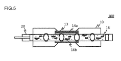
- a long sample introduction tube 20 in the cell is used equipped with a plunger operable therein.
- the inside of the sample introduction tube 20 is filled with gas A (for example, oxygen gas); a sample solution a (for example, solvent liquid); gas B (for example, carbon dioxide gas); a sample solution b (for example, protein solution); gas C (for example, argon gas); a sample solution c (for example, antibody solution); gas D (for example, helium gas); a sample solution d (for example, chemical liquid), for example, wherein different kinds of gas and solutions are beforehand introduced for the filling, these being partitioned from one another. In observation, these may be sequentially moved to be observed under different conditions.
- gas A for example, oxygen gas
- a sample solution a for example, solvent liquid
- gas B for example, carbon dioxide gas
- a sample solution b for example, protein solution
- gas C for example, argon gas
- a sample solution c for example, antibody solution
- gas D for example, helium gas
- the solution since there sometimes is a case where a reduced pressure causes bubbles in a solution with dissolved gas, it is still preferable for the solution to be degassed under a reduced pressure beforehand to be used.
- the pressure in the degassing under a reduced pressure it is desirable for the pressure in the degassing under a reduced pressure to be a lower value than in the usage conditions, specifically 2/3 atm or less, or effective to be a further lower pressure such as approximately 0.1 atm depending on the observation object.
- Such a method for introducing samples in a single channel manner has a merit that the sample-containing cell that once has been set is not needed to be taken outside the mirror body, this enabling the observations under various different kinds of conditions to be performed in a short time.
- Examples of the movement of the sample solution portions and the gas portions can include, for example, known techniques of a valve of a pressurized air chamber operable by ON/OFF switching and an electromagnetic vibratory micro pump.
- a biological sample in a solution can undergo high-resolution X-ray microscope observation.
Landscapes
- Physics & Mathematics (AREA)
- High Energy & Nuclear Physics (AREA)
- General Engineering & Computer Science (AREA)
- Engineering & Computer Science (AREA)
- General Health & Medical Sciences (AREA)
- Biochemistry (AREA)
- Analytical Chemistry (AREA)
- General Physics & Mathematics (AREA)
- Immunology (AREA)
- Pathology (AREA)
- Chemical & Material Sciences (AREA)
- Life Sciences & Earth Sciences (AREA)
- Health & Medical Sciences (AREA)
- Analysing Materials By The Use Of Radiation (AREA)
- Sampling And Sample Adjustment (AREA)
Abstract
Description
- The present invention relates to a technology for observing an X-ray microscopic image and particularly relates to a technology suitable for high-resolution X-ray microscope observation of a biological sample in a solution.
- It is known that X-ray microscopes can perform high-resolution observation of a sample in a solution, giving a useful technique in the case where the observation target sample is a biological sample particularly. Particularly, on X-rays in a wavelength range of 2.3 to 4.4 nm (corresponding to an energy range of 284 to 540 eV) generally called "water window" (soft X-rays), differences in absorption coefficient between the constituent substances of the living body are large and the relevant X-rays, while transmitted without being absorbed by water, are liable to be absorbed by carbon and nitrogen, this leading to characteristics in which proteins and the like hardly allow the relevant X-rays to be transmitted. X-ray microscope observation using the soft X-rays is suitable for observing a biological sample.
- The above-mentioned characteristics that the soft X-rays in the wavelength region of "water window" have enable an observation target object containing moisture (biological sample or sample in a solution) to be observed as it is, and in addition, enables observation in higher resolution than in the optical microscope observation because of the shorter wavelength than that of the visible light. Such reasons are promoting development of the microscope utilizing the X-rays in the "water window" wavelength region (soft X-ray microscope).
- Notably, soft X-rays in a wavelength region of "carbon window" (5.0 to 4.5 nm) showing less absorption by carbon and soft X-rays in a region of a further shorter wavelength (0.6 to 2.3 nm) are also effective for observing a biological sample.
- X-ray microscopes are categorized mainly into a scheme of irradiating the sample with an X-ray beam thinly focused using a light collecting system such as a zone plate (light collecting scheme) and a scheme of irradiating the sample with an X-ray beam from a point light source (point light source scheme).
- The X-ray microscopes in the light collecting scheme are categorized into ones of irradiating transmission type and ones of scanning transmission type. The resolution depends on processing precision of the zone plate and the like and its theoretical limit is predicted to be approximately 10 to 15 nm.
- On the other hand, the X-ray microscopes in the point light source scheme are categorized into a scheme of generating X-rays with a laser and a scheme of generating X-rays by means of irradiation with a charged particle beam such as an electron beam. There are proposed examples of the scheme of generating X-rays by means of irradiation with a charged particle beam, including a technique that an electron beam is allowed to incident on and through the surface of a sample supporting film to generate the X-rays in the sample supporting film and samples adhering to the rear face of the sample supporting film is irradiated with the X-rays (Patent Literature 1: Japanese Patent Laid-Open No.
8-43600 4565168 2-138856 - According to such a technique, exceedingly thinly focused charged particles can be allowed to be incident on the sample supporting film, suppressing a diffusion range of the charged particles to attain high resolution. Moreover, when a plurality of X-ray detectors are installed at various angles and positions below the sample supporting film (on its rear face side), inclined images depending on the installation angles can be obtained, affording as many inclined images as the number of the installed detectors in one charged particle beam scanning and also enabling a three-dimensional structure of the observation target sample to be reproduced based on these inclined images (Patent Literature 2).
- As a sample supporting member (supporting film) used for such soft X-ray microscope observation, a silicon nitride film has been widely used. Since the silicon nitride film has excellent pressure resistance, it has been thought that even when the relevant silicon nitride film is provided in a window part of a sample-containing cell inside which is under atmospheric pressure, the usage of the sample-containing cell in the microscope apparatus inside which is under a vacuum suffers no difficulty at all. For example, according to the invention disclosed in Japanese Patent Laid-Open No.
6-180400 -
- Patent Literature 1: Japanese Patent Laid-Open No.
8-43600 - Patent Literature 2: Japanese Patent No.
4565168 - Patent Literature 3: Japanese Patent Laid-Open No.
2-138856 - Patent Literature 4: Japanese Patent Laid-Open No.
6-180400 - As mentioned above, since the silicon nitride film has excellent pressure resistance, it has been thought that the sample-containing cell using such a film as a sample supporting member (supporting film) practically suffers no difficulty at all in the usage inside the X-ray microscope apparatus. Nevertheless, the inventors consider that the sample-containing cell with the conventional configuration still leaves room for further improvement.
-
Figures 1A to C are diagrams for explaining a problem arising in using the sample-containing cell with the conventional configuration in an X-ray microscope. As illustrated inFigure 1A , a sample-containingcell 100 includes acontainer part 10 having acavity part 11 for containing observation samples along with a solution.Hole parts 12 through which a sample solution is introduced for filling are provided in thecontainer part 10. In the center part of thecontainer part 10, anX-ray emission film 13 that receives irradiation with charged particles and emits soft X-rays and a firstX-ray transmission film 14a that transmits the soft X-rays and is capable of maintaining airtightness in thecavity part 11 are provided in this order in the upper portion of the figure. Similarly to the firstX-ray transmission film 14a, a secondX-ray transmission film 14b that transmits the soft X-rays from theX-ray emission film 13 and is capable of maintaining airtightness in thecavity part 11 is provided in the lower portion of the figure. - When such a sample-containing
cell 100 is filled with asample solution 15,observation samples 16 in the sample solution are held due to absorption or the like on the X-ray transmission film (on the rear face of the firstX-ray transmission film 14a in the example illustrated inFigure 1B ). In other words, the X-ray transmission film also functions as a sample supporting film. After the filling with the sample solution, thehole parts 12 are closed with sealingmembers 17 and the sample-containingcell 100 is set inside the X-ray microscope. - In performing X-ray microscope observation, the inside of the mirror body is configured to be under a vacuum. In this stage, there arises the difference between the inner pressure of the sample-containing
cell 100 and the pressure inside the mirror body of the X-ray microscope. The thicknesses of theX-ray emission film 13 and theX-ray transmission films X-ray emission film 13 and theX-ray transmission films Figure 1 C) . - Occurrence of such bending results in widening of a gap d between the first
X-ray transmission film 14a that also functions as a sample supporting film and the secondX-ray transmission film 14b in the center part of these more compared with a gap do between the end parts of theseX-ray transmission films sample solution 15 in accordance with the increase of the optical path length, causing sensitivity to deteriorate and image quality deterioration in observation image to arise. - An extent of the bending depends on the thicknesses and materials of the
X-ray emission film 13 and theX-ray transmission films sample solution 15, for example, lead to substantial increase in volume of thesample solution 15. In order to suppress this, it is thought that thesample solution 15, for example, is allowed to be at a reduced pressure for degassing in advance before the sample-containingcell 100 is set inside the X-ray microscope as an effective process. Nevertheless, such a process possibly causes exceeding evacuation in pressure inside the sample-containingcell 100. When theobservation samples 16 are relatively vulnerable ones such as living body cells, their partial breakage or the like caused by this can disadvantageously affect the morphological observation of those as a result. - The present invention is devised in view of such problems regarding the sample-containing cell with the conventional configuration as mentioned above and an object is to provide a sample-containing cell contributing to high-resolution X-ray microscope observation of a biological sample in a solution particularly.
- In order to solve the above-mentioned problems, there is provided a sample-containing cell according to a first aspect of the present invention, which is a sample-containing cell for an X-ray microscope, the sample-containing cell used in performing X-ray microscope observation in a vacuum mirror body, the sample-containing cell including: a cavity part for containing a sample solution inside; a charged particle incident window provided on one face of the sample-containing cell, for allowing charged particles to be incident on the cavity part; an X-ray emission film that receives irradiation with the charged particles and emits a characteristic X-ray in a soft X-ray region and a first X-ray transmission film that transmits the characteristic X-ray and also functions as an observation sample supporting film, the films provided in the charged particle incident window in this order; an X-ray transmission window provided on the other face of the sample-containing cell; and a second X-ray transmission film that transmits the characteristic X-ray, the film provided in the X-ray transmission window, wherein the cavity part is separated with a third X-ray transmission film that transmits the characteristic X-ray into a first cavity part on a side of the one face of the sample-containing cell and a second cavity part on a side of the other face of the sample-containing cell, and a hole part is provided in the sample-containing cell, for filling the first cavity part with the sample solution.
- Moreover, there is provided a sample-containing cell according to a second aspect of the present invention, which is a sample-containing cell for an X-ray microscope, the sample-containing cell used in performing X-ray microscope observation in a vacuum mirror body, the sample-containing cell including: a cavity part for containing a sample solution inside; a charged particle incident window provided on one face of the sample-containing cell, for allowing charged particles to be incident on the cavity part; an X-ray emission film that receives irradiation with the charged particles and emits a characteristic X-ray in a soft X-ray region and a first X-ray transmission film that transmits the characteristic X-ray and also functions as an observation sample supporting film, the films provided in the charged particle incident window in this order; an X-ray transmission window provided on the other face of the sample-containing cell; and a second X-ray transmission film that transmits the characteristic X-ray, the film provided in the X-ray transmission window, wherein a hole part for filling the cavity part with the sample solution and a gas injection part for injecting gas into the cavity part are provided in the sample-containing cell.
- Furthermore, there is provided a sample-containing cell according to a third aspect of the present invention, which is a sample-containing cell for an X-ray microscope, the sample-containing cell used in performing X-ray microscope observation in a vacuum mirror body, the sample-containing cell including: a sample introduction part equipped with a plunger operable therein for containing a sample solution inside; a charged particle incident window provided on one face of the sample-containing cell, for allowing charged particles to be incident on the sample introduction part; an X-ray emission film that receives irradiation with the charged particles and emits a characteristic X-ray in a soft X-ray region and a first X-ray transmission film that transmits the characteristic X-ray and also functions as an observation sample supporting film, the films provided in the charged particle incident window in this order; an X-ray transmission window provided on the other face of the sample-containing cell; and a second X-ray transmission film that transmits the characteristic X-ray, the film provided in the X-ray transmission window.
- It is preferable for these sample-containing cells for an X-ray microscope to include a charged particle absorption film that transmits the characteristic X-ray and shields a charged particle beam, the film provided between the X-ray emission film and the first X-ray transmission film.
- A method for observing an X-ray microscopic image according to the present invention is performed using the above-mentioned sample-containing cell according to the present invention.
- According to the present invention, even when the X-ray emission film and the X-ray transmission films are bent due to the pressure difference between the inside and outside at the interior of the mirror body, the X-ray optical path length in the sample solution does not lengthen and absorption of the X-rays by the sample solution can be suppressed. Thereby, a biological sample in a solution can undergo high-resolution X-ray microscope observation.
-
- [
Figure 1A] Figure 1A is a diagram for explaining a problem arising in using a sample-containing cell with the conventional configuration in an X-ray microscope. - [
Figure 1B] Figure 1B is a diagram for explaining the problem arising in using a sample-containing cell with the conventional configuration in an X-ray microscope. - [
Figure 1C] Figure 1C is a diagram for explaining the problem arising in using a sample-containing cell with the conventional configuration in an X-ray microscope. - [
Figure 2A] Figure 2A is a schematic cross-sectional view for explaining a basic configuration of a sample-containing cell according to a first embodiment of the present invention. - [
Figure 2B] Figure 2B is a schematic cross-sectional view for explaining the basic configuration of the sample-containing cell according to the first embodiment of the present invention. - [
Figure 2C] Figure 2C is a schematic cross-sectional view for explaining the basic configuration of the sample-containing cell according to the first embodiment of the present invention. - [
Figure 3A] Figure 3A is a schematic cross-sectional view for explaining a basic configuration of a sample-containing cell according to a second embodiment of the present invention. - [
Figure 3B] Figure 3B is a schematic cross-sectional view for explaining the basic configuration of the sample-containing cell according to the second embodiment of the present invention. - [
Figure 3C] Figure 3C is a schematic cross-sectional view for explaining the basic configuration of the sample-containing cell according to the second embodiment of the present invention. - [
Figure 3D] Figure 3D is a schematic cross-sectional view for explaining the basic configuration of the sample-containing cell according to the second embodiment of the present invention. - [
Figure 4A] Figure 4A is a diagram for explaining one example of a method for utilizing the sample-containing cell with the structure illustrated inFigures 3A to D . - [
Figure 4B] Figure 4B is a diagram for explaining one example of the method for utilizing the sample-containing cell with the structure illustrated inFigures 3A to D . - [
Figure 4C] Figure 4C is a diagram for explaining one example of the method for utilizing the sample-containing cell with the structure illustrated inFigures 3A to D . - [
Figure 4D] Figure 4D is a diagram for explaining one example of the method for utilizing the sample-containing cell with the structure illustrated inFigures 3A to D . - [
Figure 5] Figure 5 is a schematic cross-sectional view for explaining a basic configuration of a sample-containing cell according to a third embodiment of the present invention. - Hereinafter, a sample-containing cell for an X-ray microscope and a method for observing an X-ray microscopic image using the same according to the present invention will be described with reference to the drawings.
- As mentioned above, in the sample-containing cell with the conventional structure, the X-ray emission film and the X-ray transmission films are bent to be convex outward due to the pressure difference between the inside and outside at the interior of the mirror body of the X-ray microscope under a vacuum. The X-ray optical path length over the primary visual field region of the X-ray microscope observation lengthens, this causing the X-rays to be absorbed by the sample solution and image quality deterioration in observation image to arise.
- The present invention is to solve the problem as follows. A sample solution containing part and a gas containing part in a cavity part for containing a sample solution are provided inside the sample-containing cell. An increase in X-ray optical path length due to the pressure difference between the inside and outside is imposed on the above-mentioned gas containing part that does not give X-ray absorption. Thus, increase of the X-ray optical path length in the sample solution containing part is suppressed.
- Moreover, the problem is to be solved using a sample-containing cell according to another embodiment as follows. A gas bubble (air bubble) is introduced into the sample solution contained in the cavity part, an increase in X-ray optical path length due to the pressure difference between the inside and outside is imposed on the above-mentioned air bubble that does not give X-ray absorption, this enabling increase of the X-ray optical path length in the sample solution to be suppressed.
- In other words, in the sample-containing cell according to the present invention, even when the X-ray emission film and the X-ray transmission films are bent due to the pressure difference between the inside and outside at the interior of the mirror body, lengthening of the X-ray optical path length takes place in the gas portion that does not give X-ray absorption. Thus, absorption of the X-rays by the sample solution can be suppressed, this leading to no image quality deterioration in observation image.
-
Figures 2A to C are schematic cross-sectional views for explaining a basic configuration of a sample-containing cell according to a first embodiment of the present invention. InFigure 2A , acontainer part 10 of a sample-containingcell 100 is configured to be separable into anupper part 10a and alower part 10b, whereas it may be integrated into one (Figure 2B ). - In the sample-containing
cell 100, a sample solution is contained in acavity part 11 which is to be formed inside thecontainer part 10. A charged particle incident window for allowing charged particles to be incident on the cavity part is provided on one face of the sample-containingcell 100. In this charged particle incident window, anX-ray emission film 13 that receives irradiation with the charged particles and emits characteristic X-rays in the soft X-ray region and a firstX-ray transmission film 14a that transmits the characteristic X-rays and also functions as an observation sample supporting film are provided in this order. - A window for transmitting X-rays emitted from the inside of the
cavity part 11 and enabling observation from the outside (X-ray transmission window) is provided on the other face of the sample-containingcell 100. In the X-ray transmission window, a secondX-ray transmission film 14b that transmits the above-mentioned characteristic X-rays is provided. - A third
X-ray transmission film 14c that transmits the above-mentioned characteristic X-rays is provided on the lower side of theupper part 10a of thecontainer part 10. In the state where theupper part 10a of the container part and thelower part 10b of the container part are coupled together, a cavity part on theupper part 10a side of the container part (first cavity part 11 a) is sealed with the thirdX-ray transmission film 14c and the firstX-ray transmission film 14a, and a cavity part on thelower part 10b side of the container part (second cavity part 11 b) is sealed with the thirdX-ray transmission film 14c and the secondX-ray transmission film 14b. - In other words, the
cavity part 11 is separated with the thirdX-ray transmission film 14c into thefirst cavity part 11 a on the one face side of the sample-containingcell 100 and thesecond cavity part 11 b on the other face side thereof. Thefirst cavity part 11 a is filled with a sample solution through ahole part 12. -
Observation samples 16 in asample solution 15 are held due to absorption or the like on the rear face of the firstX-ray transmission film 14a. After the filling with thesample solution 15, thehole parts 12 are closed with sealingmembers 17 and the sample-containingcell 100 is set inside the X-ray microscope. Notably, as a result, thesecond cavity part 11 b is filled with gas in the environment of introducing the observation samples for the filling (generally air). - After setting the sample-containing
cell 100, theX-ray emission film 13 and theX-ray transmission films X-ray transmission film 14c is bent due to gas expansion in thesecond cavity part 11 b to be convex toward theX-ray transmission film 14a side (Figure 2C ). - Occurrence of such bending results in widening of a gap between the first
X-ray transmission film 14a that also functions as a sample supporting film and the secondX-ray transmission film 14b in the center part of these more compared with a gap between the end parts of theseX-ray transmission films X-ray transmission films X-ray transmission films - Accordingly, even when the X-ray emission film and the X-ray transmission films are bent due to the pressure difference between the inside and outside at the interior of the mirror body, lengthening of the X-ray optical path length arises in the
second cavity part 11 b (gas portion) with no occurrence of X-ray absorption, and absorption of the X-rays by thesample solution 15 is suppressed. -
Figures 3A to D are schematic cross-sectional views for explaining a basic configuration of a sample-containing cell according to a second embodiment of the present invention. - In the sample-containing
cell 100, a sample solution is contained in thecavity part 11 which is to be formed inside thecontainer part 10. The charged particle incident window for allowing charged particles to be incident on the cavity part is provided on one face of the sample-containingcell 100. In this charged particle incident window, theX-ray emission film 13 that receives irradiation with the charged particles and emits characteristic X-rays in the soft X-ray region and the firstX-ray transmission film 14a that transmits the characteristic X-rays and also functions as an observation sample supporting film are provided in this order. - A window for transmitting X-rays emitted from the inside of the
cavity part 11 and enabling observation from the outside (X-ray transmission window) is provided on the other face of the sample-containingcell 100. In the X-ray transmission window, a secondX-ray transmission film 14b that transmits the above-mentioned characteristic X-rays is provided. - The
cavity part 11 is filled with thesample solution 15 through thehole part 12. Theobservation samples 16 in thesample solution 15 are held due to absorption or the like on the rear face of the firstX-ray transmission film 14a. After the filling with thesample solution 15, thehole parts 12 are closed with the sealingmembers 17 and the sample-containingcell 100 is set inside the X-ray microscope. - A
gas injection part 18 for injecting gas into thecavity part 11 is provided in the sample-containingcell 100. - When the sample-containing
cell 100 is set, as mentioned above, theX-ray emission film 13 and theX-ray transmission films cavity part 11 through the gas injection part 18 (Figure 3C ) and thisgas bubble 19 is introduced between theX-ray transmission films Figure 3D ). - Occurrence of the bending of the
X-ray emission film 13 and theX-ray transmission films X-ray transmission film 14a that also functions as a sample supporting film and the secondX-ray transmission film 14b in the center part of these more compared with a gap between the end parts of theseX-ray transmission films gas bubble 19 by controlling the injection gas amount, absorption of the X-rays by thesample solution 15 is suppressed. - Examples of the above-mentioned injection gas can include, for example, air, helium and the like. Supposing that the energy of the X-rays is 300 eV, the thickness at which the strength attenuates to 1/e is approximately 1.5 mm for air and approximately 10 mm for helium compared with that for water being approximately 2.3 µm.
- Notably, taking account of movability of the
gas bubble 19 in thecavity part 11, it is preferable for a gap between the first X-ray transmission film and the second X-ray transmission film in the state where these films are bent under a vacuum to be 0.1 to 0.5 mm in the case of the gas being air, and moreover, to be 0.1 to 5 mm in the case of the gas being helium, still preferably 0.1 to 1 mm. - Examples of the method for injecting the gas include a method of introducing the gas into the
cavity part 11, taking advantage of the reduced pressure in the cell arising from the pressure difference between the inside and outside caused in the mirror body, and a method of injecting the gas by means of compression from the outside of thecell 100. - Since the expansion rate of liquid according to pressure is small compared with gas by nature, the expansion amount under a vacuum is small. Therefore, the interior of the cell is allowed to be under a reduced pressure. Since the state of the reduced pressure is a harsh environment for the samples such as living body cells, the state of too much reduced pressure should be prevented. Specifically, it is not desirable for the inner pressure of the cell to be 1/2 atm or less. Assuming that a volume expansion amount of the cavity part in the cell due to the reduced pressure is 1, the inner pressure of the cell can be made approximately 1/2 atm when gas of 2 in volume is injected into the cavity part.
- Notably, the sample-containing cell with the structure illustrated in
Figures 3A to D is also effective to be used as follows. -
Figures 4A to D are diagrams for explaining one example of a method for utilizing the sample-containing cell with the structure illustrated inFigures 3A to D . Once, thecavity part 11 is filled with the sample solution 15 (Figure 4A ) and theobservation samples 16 are held due to absorption or the like utilizing surface tension or the like on firstX-ray transmission film 14a (Figure 4B ). After that, thesample solution 15 is discharged from thecavity part 11 to the outside and thehole parts 12 are closed with the sealingmembers 17 to set the sample-containingcell 100 inside the X-ray microscope (Figure 4C ). - When setting the sample-containing cell, as mentioned above, the
X-ray emission film 13 and theX-ray transmission films cavity part 11 is just little in amount remaining on the surface of theobservation samples 16, absorption of the X-rays by thesample solution 15 does not take place to an extent to which the microscope observation is disadvantageously affected (Figure 4D ). - The sample-containing cell according to the present invention can be represented by various embodiments other than the above-mentioned configurations. For example, a configuration is supposed in which a charged particle absorption film that transmits the characteristic X-rays and shields the charged particle beam is included between the
X-ray emission film 13 and the firstX-ray transmission film 14a, this preferably enabling damage on the observation samples due to irradiation with the charged particle beam to be reduced. - Moreover, when the observation samples are allowed to be supported on the first X-ray transmission film, there can be various techniques other than the embodiment according to which surface tension is utilized. For example, a very thin absorption film may be provided on the sample supporting surface of the first X-ray transmission film or the observation samples may be absorbed by means of electrostatic action due to voltage application.
- When the gas bubble is injected into the cavity part, for example, a sensor, which is provided in the vicinity of the X-ray transmission window, may take a technique such as capacitance measurement and electric resistivity measurement to calculate a suitable injection gas amount or may take a technique, for example, in which the injection gas amount is regulated by means of remote manipulation, observing the status of the cell inside the mirror body, other than the embodiment according to which gas with a calculated amount based on a beforehand expected expansion amount is injected.
- Furthermore, as illustrated in
Figure 5 , a longsample introduction tube 20 in the cell is used equipped with a plunger operable therein. The inside of thesample introduction tube 20 is filled with gas A (for example, oxygen gas); a sample solution a (for example, solvent liquid); gas B (for example, carbon dioxide gas); a sample solution b (for example, protein solution); gas C (for example, argon gas); a sample solution c (for example, antibody solution); gas D (for example, helium gas); a sample solution d (for example, chemical liquid), for example, wherein different kinds of gas and solutions are beforehand introduced for the filling, these being partitioned from one another. In observation, these may be sequentially moved to be observed under different conditions. Although only a part of thesample introduction tube 20 is illustrated in the figure, a sufficiently long plunger is configured in reality. The design is made such that the above-mentioned movement of the gas portions and the sample solution portions can be performed with no difficulty. - Notably, since there sometimes is a case where a reduced pressure causes bubbles in a solution with dissolved gas, it is still preferable for the solution to be degassed under a reduced pressure beforehand to be used. Herein, it is desirable for the pressure in the degassing under a reduced pressure to be a lower value than in the usage conditions, specifically 2/3 atm or less, or effective to be a further lower pressure such as approximately 0.1 atm depending on the observation object.
- Such a method for introducing samples in a single channel manner has a merit that the sample-containing cell that once has been set is not needed to be taken outside the mirror body, this enabling the observations under various different kinds of conditions to be performed in a short time. Examples of the movement of the sample solution portions and the gas portions can include, for example, known techniques of a valve of a pressurized air chamber operable by ON/OFF switching and an electromagnetic vibratory micro pump.
- According to the present invention, a biological sample in a solution can undergo high-resolution X-ray microscope observation.
-
- 100
- Sample-containing cell
- 10
- Container part
- 10a
- Upper part
- 10b
- Lower part
- 11
- Cavity part
- 11a
- First cavity part
- 11b
- Second cavity part
- 12
- Hole part
- 13
- X-ray emission film
- 14a
- First X-ray transmission film
- 14b
- Second X-ray transmission film
- 14c
- Third X-ray transmission film
- 15
- Sample solution
- 16
- Observation sample
- 17
- Sealing member
- 18
- Gas injection part
- 19
- Gas bubble
- 20
- Sample introduction tube
Claims (6)
- A sample-containing cell for an X-ray microscope, the sample-containing cell used in performing X-ray microscope observation in a vacuum mirror body, the sample-containing cell comprising:a cavity part for containing a sample solution inside;a charged particle incident window provided on one face of the sample-containing cell, for allowing charged particles to be incident on the cavity part;an X-ray emission film that receives irradiation with the charged particles and emits a characteristic X-ray in a soft X-ray region and a first X-ray transmission film that transmits the characteristic X-ray and also functions as an observation sample supporting film, the films provided in the charged particle incident window in this order;an X-ray transmission window provided on the other face of the sample-containing cell; anda second X-ray transmission film that transmits the characteristic X-ray, the film provided in the X-ray transmission window, whereinthe cavity part is separated with a third X-ray transmission film that transmits the characteristic X-ray into a first cavity part on a side of the one face of the sample-containing cell and a second cavity part on a side of the other face of the sample-containing cell, anda hole part is provided in the sample-containing cell, for filling the first cavity part with the sample solution.
- A sample-containing cell for an X-ray microscope, the sample-containing cell used in performing X-ray microscope observation in a vacuum mirror body, the sample-containing cell comprising:a cavity part for containing a sample solution inside;a charged particle incident window provided on one face of the sample-containing cell, for allowing charged particles to be incident on the cavity part;an X-ray emission film that receives irradiation with the charged particles and emits a characteristic X-ray in a soft X-ray region and a first X-ray transmission film that transmits the characteristic X-ray and also functions as an observation sample supporting film, the films provided in the charged particle incident window in this order;an X-ray transmission window provided on the other face of the sample-containing cell; anda second X-ray transmission film that transmits the characteristic X-ray, the film provided in the X-ray transmission window, whereina hole part for filling the cavity part with the sample solution and a gas injection part for injecting gas into the cavity part are provided in the sample-containing cell.
- A sample-containing cell for an X-ray microscope, the sample-containing cell used in performing X-ray microscope observation in a vacuum mirror body, the sample-containing cell comprising:a sample introduction part equipped with a plunger operable therein for containing a sample solution inside;a charged particle incident window provided on one face of the sample-containing cell, for allowing charged particles to be incident on the sample introduction part;an X-ray emission film that receives irradiation with the charged particles and emits a characteristic X-ray in a soft X-ray region and a first X-ray transmission film that transmits the characteristic X-ray and also functions as an observation sample supporting film, the films provided in the charged particle incident window in this order;an X-ray transmission window provided on the other face of the sample-containing cell; anda second X-ray transmission film that transmits the characteristic X-ray, the film provided in the X-ray transmission window.
- The sample-containing cell for an X-ray microscope according to any one of claims 1 to 3, comprising
a charged particle absorption film that transmits the characteristic X-ray and shields a charged particle beam, the film provided between the X-ray emission film and the first X-ray transmission film. - A method for observing an X-ray microscopic image, wherein
the sample-containing cell for an X-ray microscope according to any one of claims 1 to 3 is used. - A method for observing an X-ray microscopic image, wherein
the sample-containing cell for an X-ray microscope according to Claim 4 is used.
Applications Claiming Priority (2)
| Application Number | Priority Date | Filing Date | Title |
|---|---|---|---|
| JP2011197097A JP5750763B2 (en) | 2011-09-09 | 2011-09-09 | Sample storage cell for X-ray microscope and observation method of X-ray microscope image |
| PCT/JP2012/005528 WO2013035292A1 (en) | 2011-09-09 | 2012-08-31 | Sample-containing cell for x-ray microscope and method for observing x-ray microscopic image |
Publications (3)
| Publication Number | Publication Date |
|---|---|
| EP2755209A1 true EP2755209A1 (en) | 2014-07-16 |
| EP2755209A4 EP2755209A4 (en) | 2015-05-20 |
| EP2755209B1 EP2755209B1 (en) | 2016-10-12 |
Family
ID=47831764
Family Applications (1)
| Application Number | Title | Priority Date | Filing Date |
|---|---|---|---|
| EP12830348.4A Not-in-force EP2755209B1 (en) | 2011-09-09 | 2012-08-31 | Sample-containing cell for x-ray microscope and method for observing x-ray microscopic image |
Country Status (4)
| Country | Link |
|---|---|
| US (1) | US9336918B2 (en) |
| EP (1) | EP2755209B1 (en) |
| JP (1) | JP5750763B2 (en) |
| WO (1) | WO2013035292A1 (en) |
Families Citing this family (1)
| Publication number | Priority date | Publication date | Assignee | Title |
|---|---|---|---|---|
| JP5750763B2 (en) * | 2011-09-09 | 2015-07-22 | 国立研究開発法人産業技術総合研究所 | Sample storage cell for X-ray microscope and observation method of X-ray microscope image |
Family Cites Families (19)
| Publication number | Priority date | Publication date | Assignee | Title |
|---|---|---|---|---|
| EP0319912A3 (en) | 1987-12-07 | 1990-05-09 | Nanodynamics, Incorporated | Method and apparatus for investigating materials with x-rays |
| US5107526A (en) * | 1990-10-31 | 1992-04-21 | The United State Of America As Represented By The Administrator Of The National Aeronautics And Space Administration | Water window imaging x-ray microscope |
| US5216699A (en) * | 1991-09-17 | 1993-06-01 | Olympus Optical Co., Ltd. | X-ray microscope |
| US5528646A (en) * | 1992-08-27 | 1996-06-18 | Olympus Optical Co., Ltd. | Sample vessel for X-ray microscopes |
| JP2749238B2 (en) * | 1992-12-24 | 1998-05-13 | エヌ・ティ・ティ移動通信網株式会社 | Mobile communication base station transmitting apparatus and mobile communication system |
| JPH06180400A (en) | 1992-12-11 | 1994-06-28 | Nikon Corp | Sample capsule for x-ray microscope |
| US5550378A (en) * | 1993-04-05 | 1996-08-27 | Cardiac Mariners, Incorporated | X-ray detector |
| JPH0843600A (en) | 1994-08-02 | 1996-02-16 | Horon:Kk | X-ray observing device |
| JPH08194100A (en) * | 1995-01-18 | 1996-07-30 | Shimadzu Corp | X-ray microscope and X-ray generator |
| US5680429A (en) | 1995-01-18 | 1997-10-21 | Shimadzu Corporation | X-ray generating apparatus and X-ray microscope |
| JP2642907B2 (en) * | 1995-06-14 | 1997-08-20 | 工業技術院長 | X-ray exposure equipment |
| JPH095500A (en) * | 1995-06-26 | 1997-01-10 | Shimadzu Corp | X-ray microscope |
| US5912939A (en) * | 1997-02-07 | 1999-06-15 | Hirsch; Gregory | Soft x-ray microfluoroscope |
| JP2001519022A (en) * | 1997-04-08 | 2001-10-16 | エックス−レイ・テクノロジーズ・プロプライエタリー・リミテッド | High-resolution X-ray imaging method for minute objects |
| US7145987B2 (en) * | 2003-07-24 | 2006-12-05 | Nikon Corporation | X-ray-generating devices and exposure apparatus comprising same |
| JP4565168B2 (en) | 2009-01-29 | 2010-10-20 | 独立行政法人産業技術総合研究所 | Scanning X-ray microscope and observation method of scanning X-ray microscope image |
| JP5626757B2 (en) * | 2010-02-24 | 2014-11-19 | 独立行政法人産業技術総合研究所 | X-ray microscope image observation sample support member, X-ray microscope image observation cell, and X-ray microscope |
| JP5871529B2 (en) * | 2011-08-31 | 2016-03-01 | キヤノン株式会社 | Transmission X-ray generator and X-ray imaging apparatus using the same |
| JP5750763B2 (en) * | 2011-09-09 | 2015-07-22 | 国立研究開発法人産業技術総合研究所 | Sample storage cell for X-ray microscope and observation method of X-ray microscope image |
-
2011
- 2011-09-09 JP JP2011197097A patent/JP5750763B2/en not_active Expired - Fee Related
-
2012
- 2012-08-31 EP EP12830348.4A patent/EP2755209B1/en not_active Not-in-force
- 2012-08-31 US US14/343,590 patent/US9336918B2/en not_active Expired - Fee Related
- 2012-08-31 WO PCT/JP2012/005528 patent/WO2013035292A1/en not_active Ceased
Also Published As
| Publication number | Publication date |
|---|---|
| WO2013035292A1 (en) | 2013-03-14 |
| US20140226797A1 (en) | 2014-08-14 |
| EP2755209A4 (en) | 2015-05-20 |
| JP2013057623A (en) | 2013-03-28 |
| US9336918B2 (en) | 2016-05-10 |
| EP2755209B1 (en) | 2016-10-12 |
| JP5750763B2 (en) | 2015-07-22 |
Similar Documents
| Publication | Publication Date | Title |
|---|---|---|
| EP2565900B1 (en) | Beam device and system comprising a particle beam device and an optical microscope | |
| KR101752164B1 (en) | Charged particle beam apparatus and sample image acquiring method | |
| US7745802B2 (en) | Specimen holder, specimen inspection apparatus, specimen inspection method, and method of fabricating specimen holder | |
| EP2312302A1 (en) | Apparatus and method for inspecting samples | |
| US7928380B2 (en) | Sample holder, method for observation and inspection, and apparatus for observation and inspection | |
| KR101390112B1 (en) | Charged particle beam apparatus | |
| US9466460B2 (en) | Charged particle-beam device and specimen observation method | |
| EP2975631B1 (en) | Charged particle beam device with sample platform, observation system and light emitting member | |
| US9418818B2 (en) | Charged particle beam device and sample observation method | |
| US8030622B2 (en) | Specimen holder, specimen inspection apparatus, and specimen inspection method | |
| KR101725137B1 (en) | Sample chamber for electron microscope and the electron microscope including the same | |
| EP2388575A1 (en) | Sample holder, inspection apparatus and inspection method | |
| JP5317120B2 (en) | Sample storage cell for X-ray microscope, X-ray microscope, and observation method of X-ray microscope image | |
| EP2105727B1 (en) | Scanning electron microscope comprising a film for holding a sample and a dish for receiving sample material from a damaged film | |
| US20160336145A1 (en) | Charged-Particle-Beam Device, Specimen-Image Acquisition Method, and Program Recording Medium | |
| KR102029869B1 (en) | Detachable Sample Chamber for Electron Microscope and Electron Microscope Comprising The Same | |
| US7906760B2 (en) | Inspection method and reagent solution | |
| EP2755209B1 (en) | Sample-containing cell for x-ray microscope and method for observing x-ray microscopic image | |
| JP2008210715A (en) | Charged particle beam device, and sample surface observation method using the same | |
| Grzebyk et al. | Towards a MEMS transmission point X-ray source | |
| US20100019146A1 (en) | Specimen Holder, Specimen Inspection Apparatus, and Specimen Inspection Method | |
| JP2012142129A (en) | Soft x-ray source | |
| CN116997989A (en) | Specimen holders and electron microscopes | |
| EP1953793B1 (en) | Specimen holder, specimen inspection apparatus, specimen inspection method, and method of fabricating specimen holder | |
| WO2021070340A1 (en) | Thin film damage detection function and charged particle beam device |
Legal Events
| Date | Code | Title | Description |
|---|---|---|---|
| PUAI | Public reference made under article 153(3) epc to a published international application that has entered the european phase |
Free format text: ORIGINAL CODE: 0009012 |
|
| 17P | Request for examination filed |
Effective date: 20140306 |
|
| AK | Designated contracting states |
Kind code of ref document: A1 Designated state(s): AL AT BE BG CH CY CZ DE DK EE ES FI FR GB GR HR HU IE IS IT LI LT LU LV MC MK MT NL NO PL PT RO RS SE SI SK SM TR |
|
| DAX | Request for extension of the european patent (deleted) | ||
| RA4 | Supplementary search report drawn up and despatched (corrected) |
Effective date: 20150416 |
|
| RIC1 | Information provided on ipc code assigned before grant |
Ipc: G21K 5/08 20060101ALI20150410BHEP Ipc: G21K 7/00 20060101AFI20150410BHEP |
|
| GRAP | Despatch of communication of intention to grant a patent |
Free format text: ORIGINAL CODE: EPIDOSNIGR1 |
|
| INTG | Intention to grant announced |
Effective date: 20160329 |
|
| GRAS | Grant fee paid |
Free format text: ORIGINAL CODE: EPIDOSNIGR3 |
|
| GRAA | (expected) grant |
Free format text: ORIGINAL CODE: 0009210 |
|
| AK | Designated contracting states |
Kind code of ref document: B1 Designated state(s): AL AT BE BG CH CY CZ DE DK EE ES FI FR GB GR HR HU IE IS IT LI LT LU LV MC MK MT NL NO PL PT RO RS SE SI SK SM TR |
|
| REG | Reference to a national code |
Ref country code: GB Ref legal event code: FG4D |
|
| REG | Reference to a national code |
Ref country code: CH Ref legal event code: EP |
|
| REG | Reference to a national code |
Ref country code: AT Ref legal event code: REF Ref document number: 837156 Country of ref document: AT Kind code of ref document: T Effective date: 20161015 |
|
| REG | Reference to a national code |
Ref country code: IE Ref legal event code: FG4D |
|
| REG | Reference to a national code |
Ref country code: DE Ref legal event code: R096 Ref document number: 602012024168 Country of ref document: DE |
|
| REG | Reference to a national code |
Ref country code: LT Ref legal event code: MG4D |
|
| REG | Reference to a national code |
Ref country code: NL Ref legal event code: MP Effective date: 20161012 |
|
| PG25 | Lapsed in a contracting state [announced via postgrant information from national office to epo] |
Ref country code: LV Free format text: LAPSE BECAUSE OF FAILURE TO SUBMIT A TRANSLATION OF THE DESCRIPTION OR TO PAY THE FEE WITHIN THE PRESCRIBED TIME-LIMIT Effective date: 20161012 |
|
| REG | Reference to a national code |
Ref country code: AT Ref legal event code: MK05 Ref document number: 837156 Country of ref document: AT Kind code of ref document: T Effective date: 20161012 |
|
| PG25 | Lapsed in a contracting state [announced via postgrant information from national office to epo] |
Ref country code: NO Free format text: LAPSE BECAUSE OF FAILURE TO SUBMIT A TRANSLATION OF THE DESCRIPTION OR TO PAY THE FEE WITHIN THE PRESCRIBED TIME-LIMIT Effective date: 20170112 Ref country code: SE Free format text: LAPSE BECAUSE OF FAILURE TO SUBMIT A TRANSLATION OF THE DESCRIPTION OR TO PAY THE FEE WITHIN THE PRESCRIBED TIME-LIMIT Effective date: 20161012 Ref country code: LT Free format text: LAPSE BECAUSE OF FAILURE TO SUBMIT A TRANSLATION OF THE DESCRIPTION OR TO PAY THE FEE WITHIN THE PRESCRIBED TIME-LIMIT Effective date: 20161012 Ref country code: GR Free format text: LAPSE BECAUSE OF FAILURE TO SUBMIT A TRANSLATION OF THE DESCRIPTION OR TO PAY THE FEE WITHIN THE PRESCRIBED TIME-LIMIT Effective date: 20170113 |
|
| PG25 | Lapsed in a contracting state [announced via postgrant information from national office to epo] |
Ref country code: ES Free format text: LAPSE BECAUSE OF FAILURE TO SUBMIT A TRANSLATION OF THE DESCRIPTION OR TO PAY THE FEE WITHIN THE PRESCRIBED TIME-LIMIT Effective date: 20161012 Ref country code: HR Free format text: LAPSE BECAUSE OF FAILURE TO SUBMIT A TRANSLATION OF THE DESCRIPTION OR TO PAY THE FEE WITHIN THE PRESCRIBED TIME-LIMIT Effective date: 20161012 Ref country code: RS Free format text: LAPSE BECAUSE OF FAILURE TO SUBMIT A TRANSLATION OF THE DESCRIPTION OR TO PAY THE FEE WITHIN THE PRESCRIBED TIME-LIMIT Effective date: 20161012 Ref country code: FI Free format text: LAPSE BECAUSE OF FAILURE TO SUBMIT A TRANSLATION OF THE DESCRIPTION OR TO PAY THE FEE WITHIN THE PRESCRIBED TIME-LIMIT Effective date: 20161012 Ref country code: BE Free format text: LAPSE BECAUSE OF FAILURE TO SUBMIT A TRANSLATION OF THE DESCRIPTION OR TO PAY THE FEE WITHIN THE PRESCRIBED TIME-LIMIT Effective date: 20161012 Ref country code: AT Free format text: LAPSE BECAUSE OF FAILURE TO SUBMIT A TRANSLATION OF THE DESCRIPTION OR TO PAY THE FEE WITHIN THE PRESCRIBED TIME-LIMIT Effective date: 20161012 Ref country code: NL Free format text: LAPSE BECAUSE OF FAILURE TO SUBMIT A TRANSLATION OF THE DESCRIPTION OR TO PAY THE FEE WITHIN THE PRESCRIBED TIME-LIMIT Effective date: 20161012 Ref country code: PT Free format text: LAPSE BECAUSE OF FAILURE TO SUBMIT A TRANSLATION OF THE DESCRIPTION OR TO PAY THE FEE WITHIN THE PRESCRIBED TIME-LIMIT Effective date: 20170213 Ref country code: IS Free format text: LAPSE BECAUSE OF FAILURE TO SUBMIT A TRANSLATION OF THE DESCRIPTION OR TO PAY THE FEE WITHIN THE PRESCRIBED TIME-LIMIT Effective date: 20170212 Ref country code: PL Free format text: LAPSE BECAUSE OF FAILURE TO SUBMIT A TRANSLATION OF THE DESCRIPTION OR TO PAY THE FEE WITHIN THE PRESCRIBED TIME-LIMIT Effective date: 20161012 |
|
| REG | Reference to a national code |
Ref country code: FR Ref legal event code: PLFP Year of fee payment: 6 |
|
| REG | Reference to a national code |
Ref country code: DE Ref legal event code: R097 Ref document number: 602012024168 Country of ref document: DE |
|
| PG25 | Lapsed in a contracting state [announced via postgrant information from national office to epo] |
Ref country code: SK Free format text: LAPSE BECAUSE OF FAILURE TO SUBMIT A TRANSLATION OF THE DESCRIPTION OR TO PAY THE FEE WITHIN THE PRESCRIBED TIME-LIMIT Effective date: 20161012 Ref country code: RO Free format text: LAPSE BECAUSE OF FAILURE TO SUBMIT A TRANSLATION OF THE DESCRIPTION OR TO PAY THE FEE WITHIN THE PRESCRIBED TIME-LIMIT Effective date: 20161012 Ref country code: CZ Free format text: LAPSE BECAUSE OF FAILURE TO SUBMIT A TRANSLATION OF THE DESCRIPTION OR TO PAY THE FEE WITHIN THE PRESCRIBED TIME-LIMIT Effective date: 20161012 Ref country code: DK Free format text: LAPSE BECAUSE OF FAILURE TO SUBMIT A TRANSLATION OF THE DESCRIPTION OR TO PAY THE FEE WITHIN THE PRESCRIBED TIME-LIMIT Effective date: 20161012 Ref country code: EE Free format text: LAPSE BECAUSE OF FAILURE TO SUBMIT A TRANSLATION OF THE DESCRIPTION OR TO PAY THE FEE WITHIN THE PRESCRIBED TIME-LIMIT Effective date: 20161012 |
|
| PLBE | No opposition filed within time limit |
Free format text: ORIGINAL CODE: 0009261 |
|
| STAA | Information on the status of an ep patent application or granted ep patent |
Free format text: STATUS: NO OPPOSITION FILED WITHIN TIME LIMIT |
|
| PG25 | Lapsed in a contracting state [announced via postgrant information from national office to epo] |
Ref country code: BG Free format text: LAPSE BECAUSE OF FAILURE TO SUBMIT A TRANSLATION OF THE DESCRIPTION OR TO PAY THE FEE WITHIN THE PRESCRIBED TIME-LIMIT Effective date: 20170112 Ref country code: IT Free format text: LAPSE BECAUSE OF FAILURE TO SUBMIT A TRANSLATION OF THE DESCRIPTION OR TO PAY THE FEE WITHIN THE PRESCRIBED TIME-LIMIT Effective date: 20161012 Ref country code: SM Free format text: LAPSE BECAUSE OF FAILURE TO SUBMIT A TRANSLATION OF THE DESCRIPTION OR TO PAY THE FEE WITHIN THE PRESCRIBED TIME-LIMIT Effective date: 20161012 |
|
| 26N | No opposition filed |
Effective date: 20170713 |
|
| PG25 | Lapsed in a contracting state [announced via postgrant information from national office to epo] |
Ref country code: SI Free format text: LAPSE BECAUSE OF FAILURE TO SUBMIT A TRANSLATION OF THE DESCRIPTION OR TO PAY THE FEE WITHIN THE PRESCRIBED TIME-LIMIT Effective date: 20161012 |
|
| REG | Reference to a national code |
Ref country code: CH Ref legal event code: PL |
|
| PG25 | Lapsed in a contracting state [announced via postgrant information from national office to epo] |
Ref country code: MC Free format text: LAPSE BECAUSE OF FAILURE TO SUBMIT A TRANSLATION OF THE DESCRIPTION OR TO PAY THE FEE WITHIN THE PRESCRIBED TIME-LIMIT Effective date: 20161012 |
|
| PG25 | Lapsed in a contracting state [announced via postgrant information from national office to epo] |
Ref country code: LI Free format text: LAPSE BECAUSE OF NON-PAYMENT OF DUE FEES Effective date: 20170831 Ref country code: CH Free format text: LAPSE BECAUSE OF NON-PAYMENT OF DUE FEES Effective date: 20170831 |
|
| REG | Reference to a national code |
Ref country code: IE Ref legal event code: MM4A |
|
| REG | Reference to a national code |
Ref country code: FR Ref legal event code: PLFP Year of fee payment: 7 |
|
| PG25 | Lapsed in a contracting state [announced via postgrant information from national office to epo] |
Ref country code: LU Free format text: LAPSE BECAUSE OF NON-PAYMENT OF DUE FEES Effective date: 20170831 |
|
| PG25 | Lapsed in a contracting state [announced via postgrant information from national office to epo] |
Ref country code: IE Free format text: LAPSE BECAUSE OF NON-PAYMENT OF DUE FEES Effective date: 20170831 |
|
| PG25 | Lapsed in a contracting state [announced via postgrant information from national office to epo] |
Ref country code: MT Free format text: LAPSE BECAUSE OF NON-PAYMENT OF DUE FEES Effective date: 20170831 |
|
| PG25 | Lapsed in a contracting state [announced via postgrant information from national office to epo] |
Ref country code: HU Free format text: LAPSE BECAUSE OF FAILURE TO SUBMIT A TRANSLATION OF THE DESCRIPTION OR TO PAY THE FEE WITHIN THE PRESCRIBED TIME-LIMIT; INVALID AB INITIO Effective date: 20120831 |
|
| PGFP | Annual fee paid to national office [announced via postgrant information from national office to epo] |
Ref country code: FR Payment date: 20190624 Year of fee payment: 8 |
|
| PG25 | Lapsed in a contracting state [announced via postgrant information from national office to epo] |
Ref country code: CY Free format text: LAPSE BECAUSE OF NON-PAYMENT OF DUE FEES Effective date: 20161012 |
|
| PGFP | Annual fee paid to national office [announced via postgrant information from national office to epo] |
Ref country code: GB Payment date: 20190621 Year of fee payment: 8 Ref country code: DE Payment date: 20190620 Year of fee payment: 8 |
|
| PG25 | Lapsed in a contracting state [announced via postgrant information from national office to epo] |
Ref country code: MK Free format text: LAPSE BECAUSE OF FAILURE TO SUBMIT A TRANSLATION OF THE DESCRIPTION OR TO PAY THE FEE WITHIN THE PRESCRIBED TIME-LIMIT Effective date: 20161012 |
|
| PG25 | Lapsed in a contracting state [announced via postgrant information from national office to epo] |
Ref country code: TR Free format text: LAPSE BECAUSE OF FAILURE TO SUBMIT A TRANSLATION OF THE DESCRIPTION OR TO PAY THE FEE WITHIN THE PRESCRIBED TIME-LIMIT Effective date: 20161012 |
|
| PG25 | Lapsed in a contracting state [announced via postgrant information from national office to epo] |
Ref country code: AL Free format text: LAPSE BECAUSE OF FAILURE TO SUBMIT A TRANSLATION OF THE DESCRIPTION OR TO PAY THE FEE WITHIN THE PRESCRIBED TIME-LIMIT Effective date: 20161012 |
|
| REG | Reference to a national code |
Ref country code: DE Ref legal event code: R119 Ref document number: 602012024168 Country of ref document: DE |
|
| REG | Reference to a national code |
Ref country code: DE Ref legal event code: R082 Ref document number: 602012024168 Country of ref document: DE Representative=s name: STOLMAR & PARTNER PATENTANWAELTE PARTG MBB, DE |
|
| GBPC | Gb: european patent ceased through non-payment of renewal fee |
Effective date: 20200831 |
|
| PG25 | Lapsed in a contracting state [announced via postgrant information from national office to epo] |
Ref country code: DE Free format text: LAPSE BECAUSE OF NON-PAYMENT OF DUE FEES Effective date: 20210302 Ref country code: FR Free format text: LAPSE BECAUSE OF NON-PAYMENT OF DUE FEES Effective date: 20200831 |
|
| PG25 | Lapsed in a contracting state [announced via postgrant information from national office to epo] |
Ref country code: GB Free format text: LAPSE BECAUSE OF NON-PAYMENT OF DUE FEES Effective date: 20200831 |