EP2755104A2 - Upper lid body of laptop - Google Patents
Upper lid body of laptop Download PDFInfo
- Publication number
- EP2755104A2 EP2755104A2 EP13161080.0A EP13161080A EP2755104A2 EP 2755104 A2 EP2755104 A2 EP 2755104A2 EP 13161080 A EP13161080 A EP 13161080A EP 2755104 A2 EP2755104 A2 EP 2755104A2
- Authority
- EP
- European Patent Office
- Prior art keywords
- front bezel
- rear case
- magnetic
- upper lid
- lid body
- Prior art date
- Legal status (The legal status is an assumption and is not a legal conclusion. Google has not performed a legal analysis and makes no representation as to the accuracy of the status listed.)
- Withdrawn
Links
Images




Classifications
-
- G—PHYSICS
- G06—COMPUTING OR CALCULATING; COUNTING
- G06F—ELECTRIC DIGITAL DATA PROCESSING
- G06F1/00—Details not covered by groups G06F3/00 - G06F13/00 and G06F21/00
- G06F1/16—Constructional details or arrangements
- G06F1/1601—Constructional details related to the housing of computer displays, e.g. of CRT monitors, of flat displays
-
- G—PHYSICS
- G06—COMPUTING OR CALCULATING; COUNTING
- G06F—ELECTRIC DIGITAL DATA PROCESSING
- G06F1/00—Details not covered by groups G06F3/00 - G06F13/00 and G06F21/00
- G06F1/16—Constructional details or arrangements
- G06F1/1613—Constructional details or arrangements for portable computers
-
- G—PHYSICS
- G06—COMPUTING OR CALCULATING; COUNTING
- G06F—ELECTRIC DIGITAL DATA PROCESSING
- G06F1/00—Details not covered by groups G06F3/00 - G06F13/00 and G06F21/00
- G06F1/16—Constructional details or arrangements
- G06F1/1613—Constructional details or arrangements for portable computers
- G06F1/1615—Constructional details or arrangements for portable computers with several enclosures having relative motions, each enclosure supporting at least one I/O or computing function
- G06F1/1616—Constructional details or arrangements for portable computers with several enclosures having relative motions, each enclosure supporting at least one I/O or computing function with folding flat displays, e.g. laptop computers or notebooks having a clamshell configuration, with body parts pivoting to an open position around an axis parallel to the plane they define in closed position
-
- G—PHYSICS
- G06—COMPUTING OR CALCULATING; COUNTING
- G06F—ELECTRIC DIGITAL DATA PROCESSING
- G06F1/00—Details not covered by groups G06F3/00 - G06F13/00 and G06F21/00
- G06F1/16—Constructional details or arrangements
- G06F1/1613—Constructional details or arrangements for portable computers
- G06F1/1633—Constructional details or arrangements of portable computers not specific to the type of enclosures covered by groups G06F1/1615 - G06F1/1626
- G06F1/1637—Details related to the display arrangement, including those related to the mounting of the display in the housing
Definitions
- This disclosure relates to an upper lid body, and more particularly to an upper lid body of a laptop, which uses magnetic components as a mean to assemble/disassemble.
- the upper lid body which is the body includes the display, includes a rear case (so called A member), a front bezel (so called B member), and a liquid crystal display.
- the liquid crystal display is disposed in the front bezel, and then the liquid crystal display and the front bezel is fixed to the rear case.
- the front bezel is pivotally connected to the main body by a hinge.
- appearance consideration, structure limitation, and other considerations of the front bezel are concerned, so that the design of the upper lid body is difficult to be screwless. And the aesthetic feeling of the appearance of the laptop will be destroyed by the screws fixed on the front bezel.
- the exposed screw holes may have some dirt in them, and the screws may get rusty due to the direct contact with the air, so that it is difficult to assembly/disassembly the upper lid body.
- a fixing method which uses hook structure to combine the rear case and the front bezel is proposed.
- the conventional hook structure solves the problem of aesthetic feeling caused by the screw-fixing method
- the hook structure generates new problems: the rear case and the front bezel are difficult to disassemble, so that a specific hand tool is needed to disassemble, and during the disassemble process, the hook structure may be damaged due to improper force implementation.
- the backing adhesive is also used to bond the rear case and the front bezel of the upper lid body of the laptop, but it is also difficult to disassemble the upper lid body bonding by the backing adhesive. Besides, when the rear case and the front bezel are disassembled, the backing adhesive loses the adhesive function, and new backing adhesive should be pasted, so that the rear case and the front bezel can be assembled together again.
- this disclosure provides an upper lid body of a laptop, so as to solve the issue that the aesthetic feeling of the appearance of the electronic device is destroyed, as well as the case assembling/disassembling is inconvenient.
- the upper lid body of the laptop includes a rear case, a front bezel, a display panel, and two magnetic components.
- the front bezel is combined with the rear case and forms an accommodation room.
- the display panel is disposed in the front bezel and in the accommodation room.
- the two magnetic components are respectively disposed to the rear case and the front bezel, and the positions of the two magnetic components correspond to each other.
- the rear case and the front bezel are combined with each other by the magnetic attraction of the two magnetic components.
- the upper lid body of a laptop includes a rear case, a front bezel, a display panel, and a magnetic component.
- the material of the front bezel is magnetic metal, and the front bezel is combined with the rear case and forms an accommodation room inside.
- the display panel is disposed in the front bezel and in the accommodation room.
- the magnetic component is disposed to the rear case, and the rear case and the front bezel are combined with each other by the magnetic attraction of the magnetic component and the front bezel.
- the rear case and the front bezel of the upper lid body of the laptop is able to assemble/disassemble without specific hand tools, and the integrity of the appearance of the laptop is created, so as to enhance the aesthetic feeling of the overall appearance.
- FIG. 1 is a perspective view of the laptop according to a first embodiment
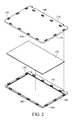
- FIG. 2 is an exploded view of the upper lid body of the laptop according to the first embodiment
- FIG. 3 is a cross-sectional view of the upper lid body of the laptop according to the first embodiment
- FIG. 4 is a perspective view of the laptop according to the first embodiment
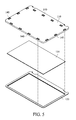
- FIG. 5 is an exploded view of the upper lid body of the laptop according to a second embodiment
- FIG. 6 is a cross-sectional view of the upper lid body of the laptop according to the second embodiment.
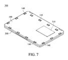
- FIG. 7 is a perspective view of the laptop according to the second embodiment.
- a laptop 300 includes an upper lid body 100 and a main body 200.
- the upper lid body 100 is able to rotate with respect to the main body 200 to the opened position or the closed position, so that users can use the laptop or carry the laptop with them easily.
- a motherboard and a plurality of electronic components are electronically disposed in the main body 200 (not shown in the figures), for example, a central processing unit, a video card, a Northbridge, and a Southbridge, so as to execute the default function of the laptop 300.
- the upper lid body 100 includes a rear case 110, a front bezel 120, a display panel 130, and at least two magnetic components 140.
- the rear case 110 is so called A member in industry, and the front bezel 120 is so called B member in industry.
- the rear case 110 is a long-rectangular thin metal board, and the front bezel 120 is a hollowed frame.
- the rear case 110 is combined with the front bezel 120 and forms an accommodation room inside.
- the display panel 130 could be a liquid crystal display, not limited as described herein.
- the display panel 130 is disposed in the front bezel 120 and in the accommodation room, and the display panel is exposed only in the hollowed part of the front bezel 120.
- the magnetic components 140 are respectively disposed in the edges of the rear case 110 and the front bezel 120.
- Each magnetic component 130 is disposed at intervals, and the position of each magnetic component 140 in the rear case 110 corresponds to the position of each magnetic component 140 in the front bezel 120.
- the magnetic components 140 could all be magnet. Or the magnetic components 140 in the rear case 110 are magnetic, and the magnetic components 140 in the front bezel 120 are made of magnetic metal, such as iron, cobalt, nickel, and the alloy thereof, not limited as described herein. Or the magnetic components 140 in the front bezel 120 are magnet, the magnetic components 140 in the rear case 110 are made of magnetic metal, such as iron, cobalt, nickel, and the alloy thereof, not limited as described herein.
- the magnetic components 140 in the rear case 110 are attracted by the magnetic force of the magnetic components 140 in the front bezel 120, as shown in FIG. 3 . Therefore, the rear case 110 and the front bezel 120 are combined with each other by the magnetic force of the magnetic components 140, such that the assembling of the upper lid body 100 of the laptop 300 is screwless. Besides, a force a little larger than the magnetic component 140 is only needed to disassemble the upper lid body 100, such that the assembling and disassembling is quick and easy.
- the positions of the magnetic components 140 are spaced from the hard disk driver 310 of the laptop 300, for avoiding the magnetic head of the hard disk driver 310 and the proper functioning of the sectors being affected by the magnetic force of the magnetic components 140.
- the positions of the magnetic components 140 also should be spaced from magnetic electronic components of the main body 200, not only the hard desk driver 310.
- a laptop 300 includes an upper lid body 100 and a main body 200 pivotally connected to each other.
- the upper lid body is able to rotate with respect to the main body 200 to the opened position or the closed position, so that users can use the laptop or carry the laptop with them easily.
- a motherboard and a plurality of electronic components are electronically disposed in the main body 200 (not shown in the figures), for example, a central processing unit, a video card, a Northbridge, and a Southbridge, so as to execute the default function of the laptop 300.
- the upper lid body 100 includes a rear case 110, a front bezel 120, a display panel 130, and at least one magnetic component 140.
- the rear case 110 is so called A member in industry, and the front bezel 120 is so called B member in industry.
- the rear case 110 is a long-rectangular thin metal board, and the front bezel 120 is a hollowed frame.
- the material of the front bezel 120 is magnetic metal, such as iron, cobalt, nickel, and the alloy thereof, not limited as described herein.
- the rear case 110 is combined with the front bezel 120 and forms an accommodation room inside.
- the display panel 130 could be a liquid crystal display, not limited as described herein.
- the display panel 130 is disposed in the front bezel 120 and in the accommodation room, and the display panel is exposed only in the hollowed part of the front bezel 120.
- the magnetic components 140 are respectively disposed in the edges of the rear case 110. Each magnetic component 130 is disposed at intervals, and the magnetic components are magnets. People having ordinary skill in the art can make proper modification to the number or deposition interval lengths of the magnetic components 140 according to the actual needs or design requirements, not limited as described herein.
- the magnetic components 140 in the rear case 110 and the front bezel 120 made of magnetic metal are attracted with each other by the magnetic force, as shown in FIG. 6 . Therefore, the rear case 110 and the front bezel 120 are combined with each other by the magnetic force, such that the assembling of the upper lid body 100 of the laptop 300 is screwless. Besides, a force a little larger than the magnetic component 140 is only needed to disassemble the upper lid body 100, such that the assembling and disassembling is quick and easy.
- the positions of the magnetic components 140 are spaced from the hard disk driver 310 of the laptop 300, for avoiding the magnetic head of the hard disk driver 310 and the proper functioning of the sectors being affected by the magnetic force of the magnetic components 140.
- the positions of the magnetic components 140 also should be spaced from magnetic electronic components of the main body 200, not only the hard desk driver 310.
- the rear case and the front bezel of the upper lid body of the laptop is able to assemble/disassemble without the specific hand tools, and the integrity of the appearance of the laptop is created, so as to enhance the aesthetic feeling of the overall appearance.
Landscapes
- Engineering & Computer Science (AREA)
- Theoretical Computer Science (AREA)
- Computer Hardware Design (AREA)
- General Engineering & Computer Science (AREA)
- Physics & Mathematics (AREA)
- Human Computer Interaction (AREA)
- General Physics & Mathematics (AREA)
- Mathematical Physics (AREA)
- Casings For Electric Apparatus (AREA)
- Devices For Indicating Variable Information By Combining Individual Elements (AREA)
Abstract
Description
- This disclosure relates to an upper lid body, and more particularly to an upper lid body of a laptop, which uses magnetic components as a mean to assemble/disassemble.
- With the advancement of the computer industry, the associated electronics have become more delicate. The development trend of current electronic devices seeks not only a better computation performance but also compactness. Take laptops as an illustration, the displays of laptops mostly are liquid crystal displays, which have advantages of high resolution, small volume, light weight, low voltage drive, and low power consumption, so that liquid crystal displays has become the mainstream of displays.
- For laptops equipped with liquid crystal displays, the upper lid body, which is the body includes the display, includes a rear case (so called A member), a front bezel (so called B member), and a liquid crystal display. The liquid crystal display is disposed in the front bezel, and then the liquid crystal display and the front bezel is fixed to the rear case. The front bezel is pivotally connected to the main body by a hinge.
However, for the assembling of the liquid crystal display of current laptops, appearance consideration, structure limitation, and other considerations of the front bezel are concerned, so that the design of the upper lid body is difficult to be screwless. And the aesthetic feeling of the appearance of the laptop will be destroyed by the screws fixed on the front bezel. Besides, after the laptop is used for a period of time, the exposed screw holes may have some dirt in them, and the screws may get rusty due to the direct contact with the air, so that it is difficult to assembly/disassembly the upper lid body. - To solve the above problem caused by the screw-fixing method, a fixing method which uses hook structure to combine the rear case and the front bezel is proposed. Though the conventional hook structure solves the problem of aesthetic feeling caused by the screw-fixing method, the hook structure generates new problems: the rear case and the front bezel are difficult to disassemble, so that a specific hand tool is needed to disassemble, and during the disassemble process, the hook structure may be damaged due to improper force implementation.
- The backing adhesive is also used to bond the rear case and the front bezel of the upper lid body of the laptop, but it is also difficult to disassemble the upper lid body bonding by the backing adhesive. Besides, when the rear case and the front bezel are disassembled, the backing adhesive loses the adhesive function, and new backing adhesive should be pasted, so that the rear case and the front bezel can be assembled together again.
- The above assembling methods, that is, screw-fixing, hook structure, and backing adhesive method, will cause inconvenience and difficulty while the upper lid body is assembling/disassembling, so how to provide a structure that can be assemble quickly and conveniently is an important issue that should be solved by the technicians in the art.
- In view of the above problems, this disclosure provides an upper lid body of a laptop, so as to solve the issue that the aesthetic feeling of the appearance of the electronic device is destroyed, as well as the case assembling/disassembling is inconvenient.
- The upper lid body of the laptop includes a rear case, a front bezel, a display panel, and two magnetic components. The front bezel is combined with the rear case and forms an accommodation room. The display panel is disposed in the front bezel and in the accommodation room. The two magnetic components are respectively disposed to the rear case and the front bezel, and the positions of the two magnetic components correspond to each other. The rear case and the front bezel are combined with each other by the magnetic attraction of the two magnetic components.
- Another kind of upper lid body of a laptop is disclosed. The upper lid body of the laptop includes a rear case, a front bezel, a display panel, and a magnetic component. The material of the front bezel is magnetic metal, and the front bezel is combined with the rear case and forms an accommodation room inside. The display panel is disposed in the front bezel and in the accommodation room. The magnetic component is disposed to the rear case, and the rear case and the front bezel are combined with each other by the magnetic attraction of the magnetic component and the front bezel.
- By the disposition of the magnetic components, the rear case and the front bezel of the upper lid body of the laptop is able to assemble/disassemble without specific hand tools, and the integrity of the appearance of the laptop is created, so as to enhance the aesthetic feeling of the overall appearance.
-
FIG. 1 is a perspective view of the laptop according to a first embodiment; -
FIG. 2 is an exploded view of the upper lid body of the laptop according to the first embodiment; -
FIG. 3 is a cross-sectional view of the upper lid body of the laptop according to the first embodiment; -
FIG. 4 is a perspective view of the laptop according to the first embodiment; -
FIG. 5 is an exploded view of the upper lid body of the laptop according to a second embodiment; -
FIG. 6 is a cross-sectional view of the upper lid body of the laptop according to the second embodiment; and -
FIG. 7 is a perspective view of the laptop according to the second embodiment. - Refer to
FIG. 1 to FIG. 4 , alaptop 300 according to the first embodiment includes anupper lid body 100 and amain body 200. Theupper lid body 100 is able to rotate with respect to themain body 200 to the opened position or the closed position, so that users can use the laptop or carry the laptop with them easily. A motherboard and a plurality of electronic components are electronically disposed in the main body 200 (not shown in the figures), for example, a central processing unit, a video card, a Northbridge, and a Southbridge, so as to execute the default function of thelaptop 300. - The
upper lid body 100 includes arear case 110, afront bezel 120, adisplay panel 130, and at least twomagnetic components 140. Therear case 110 is so called A member in industry, and thefront bezel 120 is so called B member in industry. Therear case 110 is a long-rectangular thin metal board, and thefront bezel 120 is a hollowed frame. Therear case 110 is combined with thefront bezel 120 and forms an accommodation room inside. Thedisplay panel 130 could be a liquid crystal display, not limited as described herein. Thedisplay panel 130 is disposed in thefront bezel 120 and in the accommodation room, and the display panel is exposed only in the hollowed part of thefront bezel 120. - The
magnetic components 140 are respectively disposed in the edges of therear case 110 and thefront bezel 120. Eachmagnetic component 130 is disposed at intervals, and the position of eachmagnetic component 140 in therear case 110 corresponds to the position of eachmagnetic component 140 in thefront bezel 120. - The
magnetic components 140 could all be magnet. Or themagnetic components 140 in therear case 110 are magnetic, and themagnetic components 140 in thefront bezel 120 are made of magnetic metal, such as iron, cobalt, nickel, and the alloy thereof, not limited as described herein. Or themagnetic components 140 in thefront bezel 120 are magnet, themagnetic components 140 in therear case 110 are made of magnetic metal, such as iron, cobalt, nickel, and the alloy thereof, not limited as described herein. - People having ordinary skill in the art can make proper modification to the number, deposition interval lengths, or the material of the
magnetic components 140 according to the actual needs or design requirements, not limited as described herein. Most importantly, themagnetic components 140 in therear case 110 are attracted by the magnetic force of themagnetic components 140 in thefront bezel 120, as shown inFIG. 3 . Therefore, therear case 110 and thefront bezel 120 are combined with each other by the magnetic force of themagnetic components 140, such that the assembling of theupper lid body 100 of thelaptop 300 is screwless. Besides, a force a little larger than themagnetic component 140 is only needed to disassemble theupper lid body 100, such that the assembling and disassembling is quick and easy. - Refer to
FIG. 4 , the positions of themagnetic components 140 are spaced from thehard disk driver 310 of thelaptop 300, for avoiding the magnetic head of thehard disk driver 310 and the proper functioning of the sectors being affected by the magnetic force of themagnetic components 140. The positions of themagnetic components 140 also should be spaced from magnetic electronic components of themain body 200, not only thehard desk driver 310. - Refer to
FIG. 5 to FIG. 7 , alaptop 300 according to the second embodiment includes anupper lid body 100 and amain body 200 pivotally connected to each other. The upper lid body is able to rotate with respect to themain body 200 to the opened position or the closed position, so that users can use the laptop or carry the laptop with them easily. A motherboard and a plurality of electronic components are electronically disposed in the main body 200 (not shown in the figures), for example, a central processing unit, a video card, a Northbridge, and a Southbridge, so as to execute the default function of thelaptop 300. - The
upper lid body 100 includes arear case 110, afront bezel 120, adisplay panel 130, and at least onemagnetic component 140. Therear case 110 is so called A member in industry, and thefront bezel 120 is so called B member in industry. Therear case 110 is a long-rectangular thin metal board, and thefront bezel 120 is a hollowed frame. The material of thefront bezel 120 is magnetic metal, such as iron, cobalt, nickel, and the alloy thereof, not limited as described herein. Therear case 110 is combined with thefront bezel 120 and forms an accommodation room inside. Thedisplay panel 130 could be a liquid crystal display, not limited as described herein. Thedisplay panel 130 is disposed in thefront bezel 120 and in the accommodation room, and the display panel is exposed only in the hollowed part of thefront bezel 120. - The
magnetic components 140 are respectively disposed in the edges of therear case 110. Eachmagnetic component 130 is disposed at intervals, and the magnetic components are magnets. People having ordinary skill in the art can make proper modification to the number or deposition interval lengths of themagnetic components 140 according to the actual needs or design requirements, not limited as described herein. Most importantly, themagnetic components 140 in therear case 110 and thefront bezel 120 made of magnetic metal are attracted with each other by the magnetic force, as shown inFIG. 6 . Therefore, therear case 110 and thefront bezel 120 are combined with each other by the magnetic force, such that the assembling of theupper lid body 100 of thelaptop 300 is screwless. Besides, a force a little larger than themagnetic component 140 is only needed to disassemble theupper lid body 100, such that the assembling and disassembling is quick and easy. - Refer to
FIG. 7 , the positions of themagnetic components 140 are spaced from thehard disk driver 310 of thelaptop 300, for avoiding the magnetic head of thehard disk driver 310 and the proper functioning of the sectors being affected by the magnetic force of themagnetic components 140. The positions of themagnetic components 140 also should be spaced from magnetic electronic components of themain body 200, not only thehard desk driver 310. - By the disposition of the magnetic components, the rear case and the front bezel of the upper lid body of the laptop is able to assemble/disassemble without the specific hand tools, and the integrity of the appearance of the laptop is created, so as to enhance the aesthetic feeling of the overall appearance.
Claims (9)
- An upper lid body (100) of a laptop (300), comprising:a rear case (110);a front bezel (120), combined with the rear case (110) to define an accommodation room between the rear case (110) and the front bezel (120);a display panel (130), disposed to the front bezel (120) and located in the accommodation room; andtwo magnetic components (140), respectively disposed to the rear case (110) and the front bezel (120), wherein the positions of the two magnetic components (140) correspond to each other;wherein the rear case (110) and the front bezel (120) are combined with each other by the magnetic attraction of the two magnetic components (140).
- The upper lid body (100) of claim 1, wherein the two magnetic components (140) are magnets.
- The upper lid body (100) of claim 1, wherein one of the magnetic component (140) is a magnet, and the other of the magnetic component (140) is made of magnetic metal.
- The upper lid body (100) of claim 1, wherein the two magnetic components (140) are respectively disposed at the edges of the rear case (110) and the front bezel (120).
- The upper lid body (100) of claim 4, wherein the positions of the two magnetic components (140) are spaced from a hard desk driver (310) of the laptop (300).
- An upper lid body (100) of a laptop (300), comprising:a rear case (110);a front bezel (120), combined with the rear case (110) to define an accommodation room between the rear case (110) and the front bezel (120), wherein the material of the front bezel (120) is magnetic metal;a display panel (130), disposed to the front bezel (120) and located in the accommodation room; anda magnetic component (140), disposed to the rear case (110);wherein the rear case (110) and the front bezel (120) are combined with each other by the magnetic attraction of the magnetic component (140).
- The upper lid body (100) of claim 6, wherein the magnetic component (140) is a magnet.
- The upper lid body (100) of claim 6, wherein the magnetic component (140) is disposed at the edges of the rear case (110).
- The upper lid body (100) of claim 8, wherein the position of the magnetic component (140) is spaced from a hard desk driver (310) of the laptop(300).
Applications Claiming Priority (1)
| Application Number | Priority Date | Filing Date | Title |
|---|---|---|---|
| TW102100792A TW201429360A (en) | 2013-01-09 | 2013-01-09 | Upper lid body of laptop |
Publications (2)
| Publication Number | Publication Date |
|---|---|
| EP2755104A2 true EP2755104A2 (en) | 2014-07-16 |
| EP2755104A3 EP2755104A3 (en) | 2016-07-06 |
Family
ID=48044604
Family Applications (1)
| Application Number | Title | Priority Date | Filing Date |
|---|---|---|---|
| EP13161080.0A Withdrawn EP2755104A3 (en) | 2013-01-09 | 2013-03-26 | Upper lid body of laptop |
Country Status (5)
| Country | Link |
|---|---|
| US (1) | US20140192470A1 (en) |
| EP (1) | EP2755104A3 (en) |
| JP (1) | JP2014134757A (en) |
| CN (1) | CN103914105A (en) |
| TW (1) | TW201429360A (en) |
Families Citing this family (20)
| Publication number | Priority date | Publication date | Assignee | Title |
|---|---|---|---|---|
| USD745508S1 (en) | 2013-03-15 | 2015-12-15 | Intel Corporation | Computing device with sensor |
| USD732526S1 (en) * | 2013-04-16 | 2015-06-23 | Intel Corporation | Computing device with sensor |
| CN204087716U (en) * | 2014-10-28 | 2015-01-07 | 北京京东方多媒体科技有限公司 | A kind of display device |
| CN108254953B (en) * | 2016-12-29 | 2021-02-02 | 技嘉科技股份有限公司 | Display device |
| US10303221B2 (en) | 2017-05-11 | 2019-05-28 | Microsoft Technology Licensing, Llc | Magnet biasing mechanism |
| US10555427B2 (en) * | 2017-11-08 | 2020-02-04 | Microsoft Technology Licensing, Llc | Electronic device with a magnetically attached electronic component |
| JP7168493B2 (en) * | 2018-03-23 | 2022-11-09 | 株式会社Soken | radar equipment |
| CN110782775B (en) * | 2018-07-31 | 2021-12-31 | 中强光电股份有限公司 | Display device |
| USD927482S1 (en) * | 2019-05-08 | 2021-08-10 | Dynabook Inc. | Electronic computer |
| US11086366B2 (en) * | 2019-09-05 | 2021-08-10 | Microsoft Technology Licensing, Llc | User-serviceable dimensionally-constrained device |
| CN113129735B (en) * | 2019-12-31 | 2022-12-30 | 苏州佳世达电通有限公司 | Display device with magnetic attraction type frame body |
| CN114598760B (en) * | 2020-12-07 | 2025-09-05 | Oppo广东移动通信有限公司 | An electronic device |
| US12596997B2 (en) | 2022-10-18 | 2026-04-07 | Dell Products L.P. | Information handling system and peripheral printed circuit board having non-homogeneous substrate material |
| US12306676B2 (en) | 2022-10-18 | 2025-05-20 | Dell Products L.P. | Information handling system keyboard with rapid assembly and disassembly to aid recycling |
| US12245372B2 (en) | 2022-10-18 | 2025-03-04 | Dell Products L.P. | Information handling system and peripheral printed circuit board having non-homogeneous substrate material and integrated thermal solution |
| US12085993B2 (en) * | 2022-10-18 | 2024-09-10 | Dell Products L.P. | Information handling system coupling device for improved assembly, disassembly and repair |
| US12235683B2 (en) * | 2022-10-18 | 2025-02-25 | Dell Products L.P. | Information handling system display rapid panel assembly and repair |
| US12306677B2 (en) | 2022-10-18 | 2025-05-20 | Dell Products L.P. | Information handling system with rapid assembly and disassembly to aid recycling |
| US12284429B2 (en) | 2022-10-18 | 2025-04-22 | Dell Products L.P. | Camera housing structure for enhanced manufacture assembly and repair |
| USD1101747S1 (en) * | 2023-11-17 | 2025-11-11 | Shanghai Fusaimengyang Technology Co., Ltd. | Laptop |
Family Cites Families (12)
| Publication number | Priority date | Publication date | Assignee | Title |
|---|---|---|---|---|
| US7855703B1 (en) * | 1999-07-21 | 2010-12-21 | Samsung Electronics Co., Ltd. | Liquid crystal display and an information processing apparatus having the same |
| JP2002244581A (en) * | 2001-02-14 | 2002-08-30 | Koito Ind Ltd | Information display device |
| US20050018393A1 (en) * | 2003-07-25 | 2005-01-27 | Uniwill Computer Corp. | Magnetic open/close structure for electronic device |
| JP2007003698A (en) * | 2005-06-22 | 2007-01-11 | Hitachi Ltd | Liquid crystal display |
| TWI285305B (en) * | 2005-11-07 | 2007-08-11 | High Tech Comp Corp | Auto-aligning and connecting structure between electronic device and accessory |
| TWM312853U (en) * | 2006-10-20 | 2007-05-21 | Wistron Corp | Laptop computer and changeable case for the same |
| US20090027583A1 (en) * | 2007-07-27 | 2009-01-29 | Mcbroom Michael David | Magnetic-based visual display cover arrangement |
| US20090267461A1 (en) * | 2008-04-25 | 2009-10-29 | Jan Salloum | Device front panel |
| JP2010054900A (en) * | 2008-08-29 | 2010-03-11 | Brother Ind Ltd | Casing for display |
| TWM380510U (en) * | 2010-01-12 | 2010-05-11 | Quanta Comp Inc | Laptop computer display |
| KR101084651B1 (en) * | 2010-03-05 | 2011-11-17 | 엘지전자 주식회사 | Expansion module and portable electronic device having same |
| JP3179191U (en) * | 2012-08-08 | 2012-10-18 | ラディウス株式会社 | Cover for electronic device stand |
-
2013
- 2013-01-09 TW TW102100792A patent/TW201429360A/en unknown
- 2013-03-13 CN CN201310079047.7A patent/CN103914105A/en active Pending
- 2013-03-26 EP EP13161080.0A patent/EP2755104A3/en not_active Withdrawn
- 2013-04-17 US US13/865,181 patent/US20140192470A1/en not_active Abandoned
- 2013-05-02 JP JP2013096887A patent/JP2014134757A/en active Pending
Non-Patent Citations (1)
| Title |
|---|
| None |
Also Published As
| Publication number | Publication date |
|---|---|
| TW201429360A (en) | 2014-07-16 |
| JP2014134757A (en) | 2014-07-24 |
| CN103914105A (en) | 2014-07-09 |
| US20140192470A1 (en) | 2014-07-10 |
| EP2755104A3 (en) | 2016-07-06 |
Similar Documents
| Publication | Publication Date | Title |
|---|---|---|
| US20140192470A1 (en) | Upper lid body of laptop | |
| CN209765371U (en) | information processing device | |
| US8947872B2 (en) | Holding frame for hard disk drive | |
| TW201507575A (en) | Portable electronic device | |
| US8811003B1 (en) | Keyboard support member for a computing device | |
| TWI433074B (en) | Electronic apparatus and display panel module | |
| CN110736002A (en) | Display device frame and display device | |
| CN210831037U (en) | Display device frame and display device | |
| CN105158951A (en) | Display device | |
| CN104156034B (en) | Portable electronic device and its hinge assembly | |
| CN102902300B (en) | Assembly structure and panel device for selectively assembling panel modules of different sizes | |
| US20200084896A1 (en) | Display device and frame member | |
| TW201325374A (en) | Portable electronic device | |
| CN104823124B (en) | Integral computer and host computer | |
| TW201721332A (en) | Portable electronic device | |
| CN204440237U (en) | A thin and light all-in-one computer | |
| TW201311099A (en) | Portable electronic apparatus | |
| TWI403253B (en) | Electronic apparatus | |
| CN210034860U (en) | Magnetic leveling structure and display | |
| US10555427B2 (en) | Electronic device with a magnetically attached electronic component | |
| CN203630675U (en) | Case with handle structure | |
| CN204287639U (en) | There is the LCDs of exchangeable panel | |
| CN2824089Y (en) | liquid crystal display case | |
| CN204512863U (en) | Running gear supporting frame | |
| CN204948548U (en) | Control panel structure |
Legal Events
| Date | Code | Title | Description |
|---|---|---|---|
| PUAI | Public reference made under article 153(3) epc to a published international application that has entered the european phase |
Free format text: ORIGINAL CODE: 0009012 |
|
| 17P | Request for examination filed |
Effective date: 20130326 |
|
| AK | Designated contracting states |
Kind code of ref document: A2 Designated state(s): AL AT BE BG CH CY CZ DE DK EE ES FI FR GB GR HR HU IE IS IT LI LT LU LV MC MK MT NL NO PL PT RO RS SE SI SK SM TR |
|
| AX | Request for extension of the european patent |
Extension state: BA ME |
|
| PUAL | Search report despatched |
Free format text: ORIGINAL CODE: 0009013 |
|
| AK | Designated contracting states |
Kind code of ref document: A3 Designated state(s): AL AT BE BG CH CY CZ DE DK EE ES FI FR GB GR HR HU IE IS IT LI LT LU LV MC MK MT NL NO PL PT RO RS SE SI SK SM TR |
|
| AX | Request for extension of the european patent |
Extension state: BA ME |
|
| RIC1 | Information provided on ipc code assigned before grant |
Ipc: G06F 1/16 20060101AFI20160601BHEP |
|
| RIC1 | Information provided on ipc code assigned before grant |
Ipc: G06F 1/16 20060101AFI20160913BHEP |
|
| STAA | Information on the status of an ep patent application or granted ep patent |
Free format text: STATUS: REQUEST FOR EXAMINATION WAS MADE |
|
| STAA | Information on the status of an ep patent application or granted ep patent |
Free format text: STATUS: THE APPLICATION IS DEEMED TO BE WITHDRAWN |
|
| 18D | Application deemed to be withdrawn |
Effective date: 20170110 |