EP2755091A2 - Fixing unit position-adjusting apparatus and image forming apparatus - Google Patents
Fixing unit position-adjusting apparatus and image forming apparatus Download PDFInfo
- Publication number
- EP2755091A2 EP2755091A2 EP14150169.2A EP14150169A EP2755091A2 EP 2755091 A2 EP2755091 A2 EP 2755091A2 EP 14150169 A EP14150169 A EP 14150169A EP 2755091 A2 EP2755091 A2 EP 2755091A2
- Authority
- EP
- European Patent Office
- Prior art keywords
- fixing unit
- main body
- adjusting
- image forming
- reference pin
- Prior art date
- Legal status (The legal status is an assumption and is not a legal conclusion. Google has not performed a legal analysis and makes no representation as to the accuracy of the status listed.)
- Granted
Links
- 238000003780 insertion Methods 0.000 claims abstract description 27
- 230000037431 insertion Effects 0.000 claims abstract description 27
- 108091008695 photoreceptors Proteins 0.000 description 5
- 238000010438 heat treatment Methods 0.000 description 4
- 230000007246 mechanism Effects 0.000 description 3
- 230000001105 regulatory effect Effects 0.000 description 3
- 230000015572 biosynthetic process Effects 0.000 description 2
- 230000004044 response Effects 0.000 description 2
- 230000037303 wrinkles Effects 0.000 description 2
- 238000010276 construction Methods 0.000 description 1
- 238000005516 engineering process Methods 0.000 description 1
- 238000000034 method Methods 0.000 description 1
- 238000012986 modification Methods 0.000 description 1
- 230000004048 modification Effects 0.000 description 1
- 230000003287 optical effect Effects 0.000 description 1
- 230000008569 process Effects 0.000 description 1
- 238000011144 upstream manufacturing Methods 0.000 description 1
Images


Classifications
-
- G—PHYSICS
- G03—PHOTOGRAPHY; CINEMATOGRAPHY; ANALOGOUS TECHNIQUES USING WAVES OTHER THAN OPTICAL WAVES; ELECTROGRAPHY; HOLOGRAPHY
- G03G—ELECTROGRAPHY; ELECTROPHOTOGRAPHY; MAGNETOGRAPHY
- G03G21/00—Arrangements not provided for by groups G03G13/00 - G03G19/00, e.g. cleaning, elimination of residual charge
- G03G21/16—Mechanical means for facilitating the maintenance of the apparatus, e.g. modular arrangements
- G03G21/1642—Mechanical means for facilitating the maintenance of the apparatus, e.g. modular arrangements for connecting the different parts of the apparatus
- G03G21/1647—Mechanical connection means
-
- G—PHYSICS
- G03—PHOTOGRAPHY; CINEMATOGRAPHY; ANALOGOUS TECHNIQUES USING WAVES OTHER THAN OPTICAL WAVES; ELECTROGRAPHY; HOLOGRAPHY
- G03G—ELECTROGRAPHY; ELECTROPHOTOGRAPHY; MAGNETOGRAPHY
- G03G15/00—Apparatus for electrographic processes using a charge pattern
- G03G15/20—Apparatus for electrographic processes using a charge pattern for fixing, e.g. by using heat
- G03G15/2003—Apparatus for electrographic processes using a charge pattern for fixing, e.g. by using heat using heat
- G03G15/2014—Apparatus for electrographic processes using a charge pattern for fixing, e.g. by using heat using heat using contact heat
- G03G15/2017—Structural details of the fixing unit in general, e.g. cooling means, heat shielding means
-
- G—PHYSICS
- G03—PHOTOGRAPHY; CINEMATOGRAPHY; ANALOGOUS TECHNIQUES USING WAVES OTHER THAN OPTICAL WAVES; ELECTROGRAPHY; HOLOGRAPHY
- G03G—ELECTROGRAPHY; ELECTROPHOTOGRAPHY; MAGNETOGRAPHY
- G03G15/00—Apparatus for electrographic processes using a charge pattern
- G03G15/20—Apparatus for electrographic processes using a charge pattern for fixing, e.g. by using heat
- G03G15/2003—Apparatus for electrographic processes using a charge pattern for fixing, e.g. by using heat using heat
- G03G15/2014—Apparatus for electrographic processes using a charge pattern for fixing, e.g. by using heat using heat using contact heat
- G03G15/2017—Structural details of the fixing unit in general, e.g. cooling means, heat shielding means
- G03G15/2032—Retractable heating or pressure unit
- G03G15/2035—Retractable heating or pressure unit for maintenance purposes, e.g. for removing a jammed sheet
-
- G—PHYSICS
- G03—PHOTOGRAPHY; CINEMATOGRAPHY; ANALOGOUS TECHNIQUES USING WAVES OTHER THAN OPTICAL WAVES; ELECTROGRAPHY; HOLOGRAPHY
- G03G—ELECTROGRAPHY; ELECTROPHOTOGRAPHY; MAGNETOGRAPHY
- G03G21/00—Arrangements not provided for by groups G03G13/00 - G03G19/00, e.g. cleaning, elimination of residual charge
- G03G21/16—Mechanical means for facilitating the maintenance of the apparatus, e.g. modular arrangements
- G03G21/1661—Mechanical means for facilitating the maintenance of the apparatus, e.g. modular arrangements means for handling parts of the apparatus in the apparatus
- G03G21/1685—Mechanical means for facilitating the maintenance of the apparatus, e.g. modular arrangements means for handling parts of the apparatus in the apparatus for the fixing unit
Definitions
- the first member and the second member are provided in between the fixing unit and the main body so as to mount the fixing unit on the main body in a position adjustable manner.
Landscapes
- Physics & Mathematics (AREA)
- General Physics & Mathematics (AREA)
- Electrophotography Configuration And Component (AREA)
- Fixing For Electrophotography (AREA)
Abstract
Description
- The present application claims priority to and incorporates by reference the entire contents of Japanese Patent Application No.
2013-001668 - The present invention relates to a fixing unit position-adjusting apparatus for positioning a fixing unit which fixes a toner image on a record medium, such as a recording paper sheet, with respect to a main body of an image forming apparatus, and to an image forming apparatus.
- Image forming apparatuses which form an image on a recording paper sheet with an electrophotographic system have conventionally been used as copying machines, facsimile machines, and printers. Such an electrophotographic image forming apparatus charges a photoreceptor with a charging apparatus, and then forms an electrostatic latent image on the surface of the photoreceptor through such operation as optical writing performed in accordance with a document image or image information. The electrostatic latent image is then developed by a developing apparatus into a toner image with use of a toner. The toner image that is a visible image is transferred onto a recording paper sheet that is a recording medium. The recording paper sheet is then heat-pressurized by a fixing unit so that the toner image is fixed onto the recording paper sheet. Thus, copied sheets and printed sheets are obtained.
- One example of the fixing unit for use in image forming apparatuses is a roller-type fixing unit made up of a heating roller having a heat source and a pressure roller that rotates in contact with the heating roller. The roller-type fixing unit applies heat and pressure to a recording paper sheet, which has been conveyed to between the heating roller and the pressure roller, to fix a toner image thereon. Another example is a belt-type fixing unit having an endless fixing belt stretched over between the heating roller and the fixing roller. The belt-type fixing unit applies heat and pressure to a recording paper sheet, which has been conveyed to between the fixing belt and the pressure roller, to fix a toner image thereon.
- Image forming apparatuses are required to support a wide variety of recording paper sheets, ranging from extra large-size paper sheets that are one size larger than standardized sizes to small postcard sheets with a relatively small size as well as from super-thin paper sheets to super-thick paper sheets. At the same time, high productivity and high image quality are also required. However, it was difficult to satisfy both conveying performance and image quality for the recording paper sheets.
- When the positioning accuracy of the fixing unit with respect to the recording paper sheets are poor, the recording paper sheets may enter into the fixing unit with a displaced position, which causes distorted images, generation of wrinkles, edges of the recording paper sheets being folded, and occurrence of paper jam. In such circumstances, enhanced positioning accuracy of the fixing unit is required. In response to such requirements, an adjustment mechanism is used, that adjusts a reference pin of the fixing unit in a conveyance direction.
- In one example, the adjustment mechanism is adapted to fix the position of a reference pin on the rear side of the fixing unit while adjusting the position of a reference pin on the near side of the fixing unit in the conveyance direction so as to optimize the parallelism of the fixing unit with respect to the recording paper sheets.
- Japanese Laid-open Patent Publication No.
2004-117395 - However, when the adjustment mechanism is provided, a parts count increases as a plurality of component members need to be added. This causes a problem of a complicated configuration of the apparatus. Similarly, in the case of providing the retract drive means described in Japanese Laid-open Patent Publication No.
2004-117395 - In view of the above-mentioned conventional art, there is need to provide a fixing unit position-adjusting apparatus which can position the fixing unit with a simple configuration and which can optimize the parallelism of the fixing unit with respect to recording paper sheets that enter into the fixing unit.
- It is an object of the present invention to at least partially solve the problems in the conventional technology.
- According to the present invention, there is provided: a fixing unit position-adjusting apparatus for adjusting a position of a fixing unit with respect to a main body of an image forming apparatus, comprising: a first member configured to include a positioning portion that is formed on a lateral surface of the first member, the positioning portion being engaged with a positioning portion of the main body so that the first member is mounted on the main body in a manner positionable in a left and right direction; and a second member configured to include a reference pin insertion portion that is formed to receive insertion of the reference pin of the main body, the second member being assembled with the first member.
- In the above-described fixing unit, in a state where the first member and the second member are assembled and the reference pin of the main body is inserted into the reference pin insertion portion, the first member and the second member are provided in between the fixing unit and the main body so as to mount the fixing unit on the main body in a position adjustable manner.
- The present invention also provides an image forming apparatus that includes the above-defined fixing unit position-adjusting apparatus.
- The above and other objects, features, advantages and technical and industrial significance of this invention will be better understood by reading the following detailed description of presently preferred embodiments of the invention, when considered in connection with the accompanying drawings.
-
-
FIG. 1 is a schematic configuration view of an image forming apparatus according to an embodiment of the present invention. -
FIG. 2 is a front view illustrating an assembled state of a position-adjusting apparatus in the embodiment of the present invention. -
FIG. 3 is a front view illustrating a first member of the position adjusting apparatus in the embodiment of the present invention. -
FIG. 4 is a perspective view of the first member in the embodiment of the invention. -
FIG. 5 is a perspective view of a second member in the embodiment of the invention. -
FIG. 6 is a front view illustrating a position adjustment target portion in a main body in the embodiment of the present invention. -
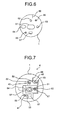
FIG. 7 is a front view illustrating adjustment by the position adjusting apparatus in the embodiment of the present invention. -
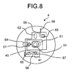
FIG. 8 is a front view illustrating the position adjustment performed with the position adjusting apparatus in an upside down orientation in the embodiment of the present invention. -
FIG. 1 is a schematic configuration view illustrating an image forming apparatus according to an embodiment of the present invention. Examples of the image forming apparatus of the present embodiment may include a copying machine, a facsimile machine, and a printer, which records an image on a recording paper sheet used as a recording medium according to an electrophotographic system. - The image forming apparatus of the present embodiment has a
main body 1 which houses each member arranged around a drum-like photoreceptor 6. An exposure apparatus 9 is provided on top of themain body 1. The exposure apparatus 9 is configured to irradiate the surface of thephotoreceptor 6 with a laser beam to form an electrostatic image. - Inside the
main body 1, atransfer roller 5, aprimary transfer belt 10, asecondary transfer roller 11, anintermediate conveyance unit 15, and afixing unit 25 are arranged around thephotoreceptor 6. Recording paper sheets are conveyed from a paper feeding tray 2 or amanual feeding tray 8. - Formation of an image with the image forming apparatus of the present embodiment is performed as shown below. First, a recording paper sheet which is a recording medium fed from the
manual feeding tray 8 or the paper feeding tray 2 is temporarily stopped at aregistration roller 3. At this time, a toner image is formed on theprimary transfer belt 10 through basic electrophotographic processes including reading, writing, charging, exposing, developing, and primary transfer, which are performed in this order in parallel with feeding of the recording paper sheet. In response to this image formation, the recording paper sheet is restarted from theregistration roller 3 and passes through a nip formed between theprimary transfer belt 10 and thesecondary transfer roller 11. By passing through the nip, an unfixed toner image is formed on the surface of the recording paper sheet. - Then, the recording paper sheet is conveyed to the
fixing unit 25 by aconveying belt 16 included in anintermediate conveyance unit 15. The recording paper sheet is then guided by a fixingentrance guide plate 17 into thefixing unit 25. When the recording paper sheet enters into the nip formed from thefixing roller 26 and thepressure roller 27, an unfixed toner image on the surface of the recording paper sheet is fixed to be a semipermanent image. The recording paper sheet is then discharged to apaper discharge tray 30. - The
fixing unit 25 is positioned on themain body 1 of the image forming apparatus. The positioning is performed with use of reference pins. A main reference and a sub reference are each provided on the front side and the rear side of the main body. The main reference is formed as a round hole, while the sub reference is formed as a noncircular hole, such as an elongated hole and an ellipse hole, to position and fix the fixingunit 25. - At the time of the positioning, if the parallelism of the fixing
unit 25 with respect to upstream units is disturbed, the position of the recording paper sheets, which are conveyed into the nip formed from the fixingroller 26 and thepressure roller 27 of the fixingunit 25, is displaced. This causes distorted images, generation of wrinkles, edges of the recording paper sheets being folded, and occurrence of paper jam. In order to solve this problem, as illustrated inFIGS. 2 to 8 , the image forming apparatus of the present embodiment includes aposition adjusting apparatus 4 that adjusts the position of the fixingunit 25 with respect to themain body 1. -
FIG. 2 is a front view of theposition adjusting apparatus 4 of the present embodiment.FIGS. 3 and 4 are respectively a front view and a perspective view of afirst member 41 of the present embodiment.FIG. 5 is a perspective view of asecond member 42 of the present embodiment.FIG. 6 is a front view illustrating a position adjustment target portion in themain body 1.FIGS. 7 and8 are front views illustrating position adjustment performed by using theposition adjusting apparatus 4 of the present embodiment. - As illustrated in
FIG. 2 , theposition adjusting apparatus 4 of the present embodiment is made up of thefirst member 41 and thesecond member 42. Thefirst member 41 and thesecond member 42 have amember body 43 and amember body 50, respectively, which are each made of a plate material. Thefirst member 41 and thesecond member 42 are assembled with use of aconnection screw 57. In the assembled state, theposition adjusting apparatus 4 is mounted on a position adjustment target portion on the side of themain body 1 of the image forming apparatus. As the position adjustment target portion on the side of themain body 1 of the image forming apparatus, a front-side plate or a drawing front-side plate, which is omitted in the drawings, is selected. -
FIGS. 3 and 4 illustrate thefirst member 41 having a mountinghole 44 formed generally in a central portion of themember body 43. Formed around the mountinghole 44 are apositioning pin 45, afirst adjusting hole 46, and asecond adjusting hole 47. The mountinghole 44 is configured to receive insertion of a referencepin insertion portion 51 of thesecond member 42 illustrated in later-describedFIG. 5 . The mountinghole 44 is formed into a horizontally-long noncircular shape such as an ellipse shape. With this configuration, the referencepin insertion portion 51 can slide in a longitudinal direction inside the mountinghole 44. - As illustrated in
FIG. 4 , thepositioning pin 45 is provided so as to protrude on an upper portion of the lateral surface of thefirst member 41. Thepositioning pin 45 is inserted into apositioning hole 62 of themain body 1 which is located on a front-side plate or a drawing front-side plate illustrated in later-describedFIG. 6 . - The
first adjusting hole 46 and thesecond adjusting hole 47 are provided at positions facing each other across the mountinghole 44. As illustrated inFIG. 3 , thefirst adjusting hole 46 is provided on a diagonally upper right side of the mountinghole 44, and thesecond adjusting hole 47 is provided on a diagonally lower left side of the mountinghole 44. These adjusting holes 46 and 47 are formed into a horizontally-long noncircular shape such as an ellipse shape. - Further as illustrated in
FIG. 3 , ascrew hole 48 for screwing theconnection screw 57 is formed in thefirst member 41. On a lower portion of thefirst member 41 in the drawings, anadjustment scale 55 to be used as a guide of position adjustment of the fixingunit 25 is marked, while on an upper portion in the drawings, areference scale 56 is formed by marking. -
FIG. 5 is a perspective view illustrating thesecond member 42. Themember body 50 of thesecond member 42 has a rectangular plate shape. In themember body 50, the referencepin insertion portion 51 and ascrew hole 53 are formed. The referencepin insertion portion 51 having an outline in a noncircular shape such as an ellipse shape is provided so as to protrude from the lateral surface of themember body 50. Areference pin 71 provided on themain body 1 side illustrated inFIG. 2 is inserted into the referencepin insertion portion 51. Accordingly, the referencepin insertion portion 51 is formed so that a circular referencepin insertion hole 52 for inserting thereference pin 71 is formed so as to pierce theportion 51. -
FIG. 6 illustrates the position adjustment target portion on the side of themain body 1 of the image forming apparatus. As mentioned before, as the target portion of themain body 1, a front-side plate or a drawing front-side plate of the image forming apparatus is selected. The target portion of themain body 1 has asupport hole 61 formed into an elongated hole having a horizontally-long noncircular shape such as an ellipse shape. As illustrated in later-describedFIGS. 7 and8 , the referencepin insertion portion 51 of thesecond member 42 is slidably inserted into thesupport hole 61. - On an upper portion of the
support hole 61 in the drawings, apositioning hole 62 in a vertically-long oval shape is formed. On a lower portion of thesupport hole 61 in the drawings, apin clearance hole 67 is formed. On upper and lower portions diagonally across thesupport hole 61, a first adjustingscrew 65 and a second adjustingscrew 66 are provided in a protruding manner. These adjusting screws 65 and 66 are inserted into the adjusting holes 46 and 47 of thefirst member 41. Areference mark 68 is marked on an upper portion of thesupport hole 61 in the drawings. Thereference mark 68 is used as a guide in performing position adjustment of the fixingunit 25. Ascrew receiving hole 63 for receiving insertion of a shaft section of theconnection screw 57 is provided on the right side of thesupport hole 61 in the drawings. -
FIG. 7 illustrates an assembly made by inserting the referencepin insertion portion 51 into the mountinghole 44 and assembling thefirst member 41 and thesecond member 42 with use of theconnection screw 57. InFIG. 7 , the assembly is mounted on the position adjustment target portion on themain body 1 side. When the assembly is mounted on the position adjustment target portion on themain body 1 side, the referencepin insertion portion 51 is inserted in thesupport hole 61, so that a height direction is put in a regulated state. - Moreover, the
positioning pin 45 of thefirst member 41 is inserted into thepositioning hole 62, while the first adjustingscrew 65 is inserted into thefirst adjusting hole 46 of thefirst member 41, and the second adjustingscrew 66 is inserted into thesecond adjusting hole 47 of thefirst member 41. At this time, the shaft section of theconnection screw 57 is inserted into thescrew receiving hole 63 of themain body 1. InFIG. 7 , thereference scale 56 of theposition adjusting apparatus 4 is aligned with thereference mark 68 of themain body 1. This indicates that the fixingunit 25 is assembled at a proper reference position. -
FIG. 8 illustrates a case of adjusting the position of the fixingunit 25. In this case, an assembly formed by assembling thefirst member 41 and thesecond member 42 is mounted upside down on the position adjustment target portion on themain body 1. Also in this case, the referencepin insertion portion 51 is inserted into thesupport hole 61 so that the height direction is regulated. - At the same time, the
positioning pin 45 of thefirst member 41 is inserted in thepin clearance hole 67, so that sliding movement in the horizontal direction is not regulated. Accordingly, thepositioning pin 45 can be slid in the horizontal direction for position adjustment. In this case, the shaft section of theconnection screw 57 is inserted into ascrew clearance hole 64 to prevent interference thereby. After position adjustment is completed, the adjusting screws 65 and 66 are used to fix the fixingunit 25. -
FIG. 8 illustrates the case where theposition adjusting apparatus 4 is moved leftward with respect to themain body 1 for position adjustment.FIG. 8 implies that theadjustment scale 55 was displaced leftward from thereference mark 68, and so the position was adjusted in the left direction. Note that similar adjustment may also be performed in the right direction. - In the present invention as described in the foregoing, the position of the fixing
unit 25 can be adjusted by assembling thefirst member 41 and thesecond member 42, inserting thereference pin 71 into the referencepin insertion portion 51, and moving thefirst member 41 in this state in the left and right direction. As a result, the fixingunit 25 can be positioned with a simple configuration. Therefore, it becomes possible to optimize the parallelism of the fixingunit 25 with respect to the recording paper sheets that enter into the fixingunit 25. - In the embodiment disclosed with referring
FIG. 7 , thepositioning pin 45 is used as a positioning portion of theposition adjusting apparatus 4, and thepositioning hole 62 is used as a positioning portion on themain body 1 side that engages with thepositioning pin 45. However, thepositioning pin 45 and thepositioning hole 62 may be reversed in this invention. That is, a positioning hole may be formed in theposition adjusting apparatus 4, and a positioning pin may be formed on themain body 1 side. - According to the present invention, the position of the fixing unit can be adjusted by assembling the first member and the second member, inserting the reference pin of the main body into the reference pin insertion portion, and moving the first member in the left and right direction. This makes it possible to position the fixing unit with a simple configuration and to also optimize the parallelism of the fixing unit with respect to recording paper sheets that enter into the fixing unit.
- Although the invention has been described with respect to specific embodiments for a complete and clear disclosure, the appended claims are not to be thus limited but are to be construed as embodying all modifications and alternative constructions that may occur to one skilled in the art that fairly fall within the basic teaching herein set forth.
Claims (6)
- A fixing unit position-adjusting apparatus for adjusting a position of a fixing unit with respect to a main body (1) of an image forming apparatus, comprising:a first member (41) configured to include a positioning portion (45) that is formed on a lateral surface of the first member (41), the positioning portion (45) being engaged with a positioning portion (62) of the main body (1) so that the first member (41) is mounted on the main body (1) in a manner positionable in a left and right direction; anda second member (42) configured to include a reference pin insertion portion (51) that is formed to receive insertion of a reference pin (71) of the main body, the second member (42) being assembled with the first member (41), whereinin a state where the first member (41) and the second member (42) are assembled and the reference pin (71) of the main body (1) is inserted into the reference pin insertion portion (51), the first member (41) and the second member (42) are provided in between the fixing unit and the main body so as to mount the fixing unit on the main body (1) in a position adjustable manner.
- The fixing unit position-adjusting apparatus according to claim 1, wherein
the first member (41) is configured to be mounted upside down onto the main body (1). - The fixing unit position-adjusting apparatus according to claim 1 or 2, wherein
the first member (1) is configured to further include a mounting hole (44) that is formed to receive insertion of the reference pin insertion portion (51) in a position adjustable manner. - The fixing unit position-adjusting apparatus according to any one of claims 1 to 3, wherein
the first member (41) is configured to further include adjusting holes (46, 47) that are formed on upper and lower portions on the lateral surface of the first member (41), the adjusting holes (46, 47) receiving insertion of adjusting screws (65, 66) of the main body (1) in a position adjustable manner. - The fixing unit position-adjusting apparatus according to any one of claims 1 to 4, wherein
the first member (41) is configured to include an adjustment scale (56) that is formed to be used as a guide of position adjustment with respect to the main body (1). - An image forming apparatus, comprising the fixing unit position-adjusting apparatus according to any one of claims 1 to 5.
Applications Claiming Priority (1)
| Application Number | Priority Date | Filing Date | Title |
|---|---|---|---|
| JP2013001668A JP6160084B2 (en) | 2013-01-09 | 2013-01-09 | Fixing unit position adjusting device and image forming apparatus |
Publications (3)
| Publication Number | Publication Date |
|---|---|
| EP2755091A2 true EP2755091A2 (en) | 2014-07-16 |
| EP2755091A3 EP2755091A3 (en) | 2016-12-14 |
| EP2755091B1 EP2755091B1 (en) | 2019-03-06 |
Family
ID=49999708
Family Applications (1)
| Application Number | Title | Priority Date | Filing Date |
|---|---|---|---|
| EP14150169.2A Active EP2755091B1 (en) | 2013-01-09 | 2014-01-03 | Fixing unit position-adjusting apparatus and image forming apparatus |
Country Status (4)
| Country | Link |
|---|---|
| US (1) | US9176444B2 (en) |
| EP (1) | EP2755091B1 (en) |
| JP (1) | JP6160084B2 (en) |
| CN (2) | CN106950809B (en) |
Families Citing this family (6)
| Publication number | Priority date | Publication date | Assignee | Title |
|---|---|---|---|---|
| US9740143B2 (en) | 2015-03-31 | 2017-08-22 | Ricoh Company, Ltd. | Image forming apparatus |
| JP6711132B2 (en) | 2016-05-20 | 2020-06-17 | 株式会社リコー | Image forming apparatus control method |
| JP6813791B2 (en) | 2016-05-20 | 2021-01-13 | 株式会社リコー | Control method of image forming apparatus |
| JP7163157B2 (en) * | 2018-12-05 | 2022-10-31 | 東芝テック株式会社 | Fixing device and image forming device |
| US11513457B2 (en) | 2020-05-21 | 2022-11-29 | Ricoh Company, Ltd. | Fixing device and image forming apparatus incorporating same |
| JP7663861B2 (en) | 2021-07-05 | 2025-04-17 | 株式会社リコー | Contact-separation device, fixing device and image forming apparatus |
Citations (1)
| Publication number | Priority date | Publication date | Assignee | Title |
|---|---|---|---|---|
| JP2004117395A (en) | 2002-09-20 | 2004-04-15 | Ricoh Co Ltd | Image forming device |
Family Cites Families (9)
| Publication number | Priority date | Publication date | Assignee | Title |
|---|---|---|---|---|
| JP2763884B2 (en) * | 1987-09-28 | 1998-06-11 | 株式会社リコー | Color image forming equipment |
| JPH0597267A (en) * | 1991-10-08 | 1993-04-20 | Fuji Xerox Co Ltd | Shaft supporting device |
| JP4480446B2 (en) * | 2004-04-02 | 2010-06-16 | 京セラミタ株式会社 | Fixing device position adjustment device |
| JP2007193087A (en) * | 2006-01-19 | 2007-08-02 | Ricoh Co Ltd | Image forming apparatus, fixing apparatus, and recording material conveyance direction correction method |
| JP4785613B2 (en) * | 2006-05-15 | 2011-10-05 | 株式会社東芝 | Transfer belt unit and image forming apparatus having the same |
| JP4918396B2 (en) * | 2007-04-23 | 2012-04-18 | 京セラミタ株式会社 | Image forming apparatus |
| JP4403191B2 (en) * | 2007-07-06 | 2010-01-20 | 株式会社沖データ | Image forming unit and image forming apparatus |
| JP5099841B2 (en) * | 2008-04-18 | 2012-12-19 | 株式会社リコー | Image forming apparatus |
| JP5692515B2 (en) * | 2011-01-12 | 2015-04-01 | 村田機械株式会社 | Image reading device |
-
2013
- 2013-01-09 JP JP2013001668A patent/JP6160084B2/en not_active Expired - Fee Related
- 2013-12-26 US US14/141,281 patent/US9176444B2/en not_active Expired - Fee Related
-
2014
- 2014-01-03 EP EP14150169.2A patent/EP2755091B1/en active Active
- 2014-01-08 CN CN201710355667.7A patent/CN106950809B/en not_active Expired - Fee Related
- 2014-01-08 CN CN201410008548.0A patent/CN103913980A/en active Pending
Patent Citations (1)
| Publication number | Priority date | Publication date | Assignee | Title |
|---|---|---|---|---|
| JP2004117395A (en) | 2002-09-20 | 2004-04-15 | Ricoh Co Ltd | Image forming device |
Also Published As
| Publication number | Publication date |
|---|---|
| JP6160084B2 (en) | 2017-07-12 |
| US9176444B2 (en) | 2015-11-03 |
| CN103913980A (en) | 2014-07-09 |
| US20140193175A1 (en) | 2014-07-10 |
| CN106950809B (en) | 2020-01-10 |
| JP2014134624A (en) | 2014-07-24 |
| CN106950809A (en) | 2017-07-14 |
| EP2755091A3 (en) | 2016-12-14 |
| EP2755091B1 (en) | 2019-03-06 |
Similar Documents
| Publication | Publication Date | Title |
|---|---|---|
| US9176444B2 (en) | Fixing unit position-adjusting apparatus and image forming apparatus | |
| CN102170504B (en) | Image reading device and image forming apparatus | |
| US20100133743A1 (en) | Sheet feeding apparutus and image forming apparatus | |
| JP4480446B2 (en) | Fixing device position adjustment device | |
| US20180259897A1 (en) | Image forming apparatus frame | |
| CN115236960B (en) | Image forming apparatus having a plurality of image forming units | |
| US11835902B2 (en) | Image reading apparatus and image forming system | |
| US11124374B2 (en) | Sheet conveying apparatus, image reading apparatus therewith and image forming apparatus therewith | |
| US11040842B2 (en) | Sheet supporting apparatus and image forming apparatus | |
| JP6185897B2 (en) | Image forming apparatus | |
| US20060033969A1 (en) | Medium feeding apparatus, document feeding apparatus, and paper feeder | |
| JP2007193087A (en) | Image forming apparatus, fixing apparatus, and recording material conveyance direction correction method | |
| US20260050233A1 (en) | Transport device and image forming apparatus | |
| US7400846B2 (en) | Image forming apparatus having guide supporting brackets including paper transportation guides | |
| US20170052497A1 (en) | Recording-medium supplying device and image forming apparatus | |
| JP5610918B2 (en) | Sheet body conveying apparatus and image forming apparatus provided with the sheet body conveying apparatus | |
| JP2007217156A (en) | Sheet delivery mechanism and image forming device equipped with it | |
| JP2006168966A (en) | Paper feeding cassette | |
| JP6185405B2 (en) | Image forming apparatus | |
| JP2016030654A (en) | Printer | |
| JP2013152408A (en) | Image forming apparatus | |
| JP2007225723A (en) | Image forming apparatus and method for maintaining image forming apparatus | |
| JP2010173800A (en) | Paper feeder and image forming device | |
| JP2018180398A (en) | Image forming device | |
| JP2016078956A (en) | Paper feeding device and image forming apparatus |
Legal Events
| Date | Code | Title | Description |
|---|---|---|---|
| PUAI | Public reference made under article 153(3) epc to a published international application that has entered the european phase |
Free format text: ORIGINAL CODE: 0009012 |
|
| 17P | Request for examination filed |
Effective date: 20140103 |
|
| AK | Designated contracting states |
Kind code of ref document: A2 Designated state(s): AL AT BE BG CH CY CZ DE DK EE ES FI FR GB GR HR HU IE IS IT LI LT LU LV MC MK MT NL NO PL PT RO RS SE SI SK SM TR |
|
| AX | Request for extension of the european patent |
Extension state: BA ME |
|
| PUAL | Search report despatched |
Free format text: ORIGINAL CODE: 0009013 |
|
| AK | Designated contracting states |
Kind code of ref document: A3 Designated state(s): AL AT BE BG CH CY CZ DE DK EE ES FI FR GB GR HR HU IE IS IT LI LT LU LV MC MK MT NL NO PL PT RO RS SE SI SK SM TR |
|
| AX | Request for extension of the european patent |
Extension state: BA ME |
|
| RIC1 | Information provided on ipc code assigned before grant |
Ipc: G03G 21/16 20060101ALI20161109BHEP Ipc: G03G 15/20 20060101AFI20161109BHEP |
|
| GRAP | Despatch of communication of intention to grant a patent |
Free format text: ORIGINAL CODE: EPIDOSNIGR1 |
|
| STAA | Information on the status of an ep patent application or granted ep patent |
Free format text: STATUS: GRANT OF PATENT IS INTENDED |
|
| INTG | Intention to grant announced |
Effective date: 20180925 |
|
| GRAS | Grant fee paid |
Free format text: ORIGINAL CODE: EPIDOSNIGR3 |
|
| GRAA | (expected) grant |
Free format text: ORIGINAL CODE: 0009210 |
|
| STAA | Information on the status of an ep patent application or granted ep patent |
Free format text: STATUS: THE PATENT HAS BEEN GRANTED |
|
| AK | Designated contracting states |
Kind code of ref document: B1 Designated state(s): AL AT BE BG CH CY CZ DE DK EE ES FI FR GB GR HR HU IE IS IT LI LT LU LV MC MK MT NL NO PL PT RO RS SE SI SK SM TR |
|
| REG | Reference to a national code |
Ref country code: GB Ref legal event code: FG4D |
|
| REG | Reference to a national code |
Ref country code: AT Ref legal event code: REF Ref document number: 1105354 Country of ref document: AT Kind code of ref document: T Effective date: 20190315 Ref country code: CH Ref legal event code: EP |
|
| REG | Reference to a national code |
Ref country code: DE Ref legal event code: R096 Ref document number: 602014042170 Country of ref document: DE |
|
| REG | Reference to a national code |
Ref country code: IE Ref legal event code: FG4D |
|
| REG | Reference to a national code |
Ref country code: NL Ref legal event code: MP Effective date: 20190306 |
|
| REG | Reference to a national code |
Ref country code: LT Ref legal event code: MG4D |
|
| PG25 | Lapsed in a contracting state [announced via postgrant information from national office to epo] |
Ref country code: SE Free format text: LAPSE BECAUSE OF FAILURE TO SUBMIT A TRANSLATION OF THE DESCRIPTION OR TO PAY THE FEE WITHIN THE PRESCRIBED TIME-LIMIT Effective date: 20190306 Ref country code: NO Free format text: LAPSE BECAUSE OF FAILURE TO SUBMIT A TRANSLATION OF THE DESCRIPTION OR TO PAY THE FEE WITHIN THE PRESCRIBED TIME-LIMIT Effective date: 20190606 Ref country code: LT Free format text: LAPSE BECAUSE OF FAILURE TO SUBMIT A TRANSLATION OF THE DESCRIPTION OR TO PAY THE FEE WITHIN THE PRESCRIBED TIME-LIMIT Effective date: 20190306 Ref country code: FI Free format text: LAPSE BECAUSE OF FAILURE TO SUBMIT A TRANSLATION OF THE DESCRIPTION OR TO PAY THE FEE WITHIN THE PRESCRIBED TIME-LIMIT Effective date: 20190306 |
|
| PG25 | Lapsed in a contracting state [announced via postgrant information from national office to epo] |
Ref country code: BG Free format text: LAPSE BECAUSE OF FAILURE TO SUBMIT A TRANSLATION OF THE DESCRIPTION OR TO PAY THE FEE WITHIN THE PRESCRIBED TIME-LIMIT Effective date: 20190606 Ref country code: RS Free format text: LAPSE BECAUSE OF FAILURE TO SUBMIT A TRANSLATION OF THE DESCRIPTION OR TO PAY THE FEE WITHIN THE PRESCRIBED TIME-LIMIT Effective date: 20190306 Ref country code: HR Free format text: LAPSE BECAUSE OF FAILURE TO SUBMIT A TRANSLATION OF THE DESCRIPTION OR TO PAY THE FEE WITHIN THE PRESCRIBED TIME-LIMIT Effective date: 20190306 Ref country code: LV Free format text: LAPSE BECAUSE OF FAILURE TO SUBMIT A TRANSLATION OF THE DESCRIPTION OR TO PAY THE FEE WITHIN THE PRESCRIBED TIME-LIMIT Effective date: 20190306 Ref country code: NL Free format text: LAPSE BECAUSE OF FAILURE TO SUBMIT A TRANSLATION OF THE DESCRIPTION OR TO PAY THE FEE WITHIN THE PRESCRIBED TIME-LIMIT Effective date: 20190306 Ref country code: GR Free format text: LAPSE BECAUSE OF FAILURE TO SUBMIT A TRANSLATION OF THE DESCRIPTION OR TO PAY THE FEE WITHIN THE PRESCRIBED TIME-LIMIT Effective date: 20190607 |
|
| REG | Reference to a national code |
Ref country code: AT Ref legal event code: MK05 Ref document number: 1105354 Country of ref document: AT Kind code of ref document: T Effective date: 20190306 |
|
| PG25 | Lapsed in a contracting state [announced via postgrant information from national office to epo] |
Ref country code: AL Free format text: LAPSE BECAUSE OF FAILURE TO SUBMIT A TRANSLATION OF THE DESCRIPTION OR TO PAY THE FEE WITHIN THE PRESCRIBED TIME-LIMIT Effective date: 20190306 Ref country code: SK Free format text: LAPSE BECAUSE OF FAILURE TO SUBMIT A TRANSLATION OF THE DESCRIPTION OR TO PAY THE FEE WITHIN THE PRESCRIBED TIME-LIMIT Effective date: 20190306 Ref country code: PT Free format text: LAPSE BECAUSE OF FAILURE TO SUBMIT A TRANSLATION OF THE DESCRIPTION OR TO PAY THE FEE WITHIN THE PRESCRIBED TIME-LIMIT Effective date: 20190706 Ref country code: ES Free format text: LAPSE BECAUSE OF FAILURE TO SUBMIT A TRANSLATION OF THE DESCRIPTION OR TO PAY THE FEE WITHIN THE PRESCRIBED TIME-LIMIT Effective date: 20190306 Ref country code: RO Free format text: LAPSE BECAUSE OF FAILURE TO SUBMIT A TRANSLATION OF THE DESCRIPTION OR TO PAY THE FEE WITHIN THE PRESCRIBED TIME-LIMIT Effective date: 20190306 Ref country code: CZ Free format text: LAPSE BECAUSE OF FAILURE TO SUBMIT A TRANSLATION OF THE DESCRIPTION OR TO PAY THE FEE WITHIN THE PRESCRIBED TIME-LIMIT Effective date: 20190306 Ref country code: EE Free format text: LAPSE BECAUSE OF FAILURE TO SUBMIT A TRANSLATION OF THE DESCRIPTION OR TO PAY THE FEE WITHIN THE PRESCRIBED TIME-LIMIT Effective date: 20190306 Ref country code: IT Free format text: LAPSE BECAUSE OF FAILURE TO SUBMIT A TRANSLATION OF THE DESCRIPTION OR TO PAY THE FEE WITHIN THE PRESCRIBED TIME-LIMIT Effective date: 20190306 |
|
| PG25 | Lapsed in a contracting state [announced via postgrant information from national office to epo] |
Ref country code: SM Free format text: LAPSE BECAUSE OF FAILURE TO SUBMIT A TRANSLATION OF THE DESCRIPTION OR TO PAY THE FEE WITHIN THE PRESCRIBED TIME-LIMIT Effective date: 20190306 Ref country code: PL Free format text: LAPSE BECAUSE OF FAILURE TO SUBMIT A TRANSLATION OF THE DESCRIPTION OR TO PAY THE FEE WITHIN THE PRESCRIBED TIME-LIMIT Effective date: 20190306 |
|
| REG | Reference to a national code |
Ref country code: DE Ref legal event code: R097 Ref document number: 602014042170 Country of ref document: DE |
|
| PG25 | Lapsed in a contracting state [announced via postgrant information from national office to epo] |
Ref country code: IS Free format text: LAPSE BECAUSE OF FAILURE TO SUBMIT A TRANSLATION OF THE DESCRIPTION OR TO PAY THE FEE WITHIN THE PRESCRIBED TIME-LIMIT Effective date: 20190706 Ref country code: AT Free format text: LAPSE BECAUSE OF FAILURE TO SUBMIT A TRANSLATION OF THE DESCRIPTION OR TO PAY THE FEE WITHIN THE PRESCRIBED TIME-LIMIT Effective date: 20190306 |
|
| PLBE | No opposition filed within time limit |
Free format text: ORIGINAL CODE: 0009261 |
|
| STAA | Information on the status of an ep patent application or granted ep patent |
Free format text: STATUS: NO OPPOSITION FILED WITHIN TIME LIMIT |
|
| PG25 | Lapsed in a contracting state [announced via postgrant information from national office to epo] |
Ref country code: DK Free format text: LAPSE BECAUSE OF FAILURE TO SUBMIT A TRANSLATION OF THE DESCRIPTION OR TO PAY THE FEE WITHIN THE PRESCRIBED TIME-LIMIT Effective date: 20190306 |
|
| 26N | No opposition filed |
Effective date: 20191209 |
|
| PG25 | Lapsed in a contracting state [announced via postgrant information from national office to epo] |
Ref country code: SI Free format text: LAPSE BECAUSE OF FAILURE TO SUBMIT A TRANSLATION OF THE DESCRIPTION OR TO PAY THE FEE WITHIN THE PRESCRIBED TIME-LIMIT Effective date: 20190306 |
|
| PG25 | Lapsed in a contracting state [announced via postgrant information from national office to epo] |
Ref country code: TR Free format text: LAPSE BECAUSE OF FAILURE TO SUBMIT A TRANSLATION OF THE DESCRIPTION OR TO PAY THE FEE WITHIN THE PRESCRIBED TIME-LIMIT Effective date: 20190306 |
|
| PG25 | Lapsed in a contracting state [announced via postgrant information from national office to epo] |
Ref country code: MC Free format text: LAPSE BECAUSE OF FAILURE TO SUBMIT A TRANSLATION OF THE DESCRIPTION OR TO PAY THE FEE WITHIN THE PRESCRIBED TIME-LIMIT Effective date: 20190306 |
|
| REG | Reference to a national code |
Ref country code: CH Ref legal event code: PL |
|
| REG | Reference to a national code |
Ref country code: BE Ref legal event code: MM Effective date: 20200131 |
|
| PG25 | Lapsed in a contracting state [announced via postgrant information from national office to epo] |
Ref country code: LU Free format text: LAPSE BECAUSE OF NON-PAYMENT OF DUE FEES Effective date: 20200103 |
|
| PG25 | Lapsed in a contracting state [announced via postgrant information from national office to epo] |
Ref country code: LI Free format text: LAPSE BECAUSE OF NON-PAYMENT OF DUE FEES Effective date: 20200131 Ref country code: BE Free format text: LAPSE BECAUSE OF NON-PAYMENT OF DUE FEES Effective date: 20200131 Ref country code: CH Free format text: LAPSE BECAUSE OF NON-PAYMENT OF DUE FEES Effective date: 20200131 |
|
| PG25 | Lapsed in a contracting state [announced via postgrant information from national office to epo] |
Ref country code: IE Free format text: LAPSE BECAUSE OF NON-PAYMENT OF DUE FEES Effective date: 20200103 |
|
| PGFP | Annual fee paid to national office [announced via postgrant information from national office to epo] |
Ref country code: GB Payment date: 20220119 Year of fee payment: 9 Ref country code: DE Payment date: 20220119 Year of fee payment: 9 |
|
| PG25 | Lapsed in a contracting state [announced via postgrant information from national office to epo] |
Ref country code: MT Free format text: LAPSE BECAUSE OF FAILURE TO SUBMIT A TRANSLATION OF THE DESCRIPTION OR TO PAY THE FEE WITHIN THE PRESCRIBED TIME-LIMIT Effective date: 20190306 Ref country code: CY Free format text: LAPSE BECAUSE OF FAILURE TO SUBMIT A TRANSLATION OF THE DESCRIPTION OR TO PAY THE FEE WITHIN THE PRESCRIBED TIME-LIMIT Effective date: 20190306 |
|
| PGFP | Annual fee paid to national office [announced via postgrant information from national office to epo] |
Ref country code: FR Payment date: 20220119 Year of fee payment: 9 |
|
| PG25 | Lapsed in a contracting state [announced via postgrant information from national office to epo] |
Ref country code: MK Free format text: LAPSE BECAUSE OF FAILURE TO SUBMIT A TRANSLATION OF THE DESCRIPTION OR TO PAY THE FEE WITHIN THE PRESCRIBED TIME-LIMIT Effective date: 20190306 |
|
| REG | Reference to a national code |
Ref country code: DE Ref legal event code: R119 Ref document number: 602014042170 Country of ref document: DE |
|
| GBPC | Gb: european patent ceased through non-payment of renewal fee |
Effective date: 20230103 |
|
| PG25 | Lapsed in a contracting state [announced via postgrant information from national office to epo] |
Ref country code: GB Free format text: LAPSE BECAUSE OF NON-PAYMENT OF DUE FEES Effective date: 20230103 Ref country code: DE Free format text: LAPSE BECAUSE OF NON-PAYMENT OF DUE FEES Effective date: 20230801 |
|
| PG25 | Lapsed in a contracting state [announced via postgrant information from national office to epo] |
Ref country code: FR Free format text: LAPSE BECAUSE OF NON-PAYMENT OF DUE FEES Effective date: 20230131 |