EP2755065A1 - Heat ray shielding material - Google Patents
Heat ray shielding material Download PDFInfo
- Publication number
- EP2755065A1 EP2755065A1 EP20120830109 EP12830109A EP2755065A1 EP 2755065 A1 EP2755065 A1 EP 2755065A1 EP 20120830109 EP20120830109 EP 20120830109 EP 12830109 A EP12830109 A EP 12830109A EP 2755065 A1 EP2755065 A1 EP 2755065A1
- Authority
- EP
- European Patent Office
- Prior art keywords
- metal particles
- tabular
- containing layer
- heat ray
- shielding material
- Prior art date
- Legal status (The legal status is an assumption and is not a legal conclusion. Google has not performed a legal analysis and makes no representation as to the accuracy of the status listed.)
- Withdrawn
Links
- 239000000463 material Substances 0.000 title claims abstract description 167
- 239000002923 metal particle Substances 0.000 claims abstract description 378
- 238000002834 transmittance Methods 0.000 claims abstract description 33
- 239000002245 particle Substances 0.000 claims description 158
- 229910052709 silver Inorganic materials 0.000 claims description 48
- 239000004332 silver Substances 0.000 claims description 48
- 239000000758 substrate Substances 0.000 claims description 45
- 229920000642 polymer Polymers 0.000 claims description 28
- 229910052751 metal Inorganic materials 0.000 claims description 21
- 239000002184 metal Substances 0.000 claims description 21
- 229920001225 polyester resin Polymers 0.000 claims description 8
- 239000004645 polyester resin Substances 0.000 claims description 8
- 229920005749 polyurethane resin Polymers 0.000 claims description 5
- 239000010410 layer Substances 0.000 description 257
- BQCADISMDOOEFD-UHFFFAOYSA-N Silver Chemical compound [Ag] BQCADISMDOOEFD-UHFFFAOYSA-N 0.000 description 47
- 238000000576 coating method Methods 0.000 description 33
- 238000000034 method Methods 0.000 description 32
- 239000002250 absorbent Substances 0.000 description 30
- 230000002745 absorbent Effects 0.000 description 30
- 239000006185 dispersion Substances 0.000 description 29
- 239000011248 coating agent Substances 0.000 description 28
- 229910044991 metal oxide Inorganic materials 0.000 description 25
- 150000004706 metal oxides Chemical class 0.000 description 25
- 239000012790 adhesive layer Substances 0.000 description 20
- 239000007788 liquid Substances 0.000 description 20
- 230000000052 comparative effect Effects 0.000 description 19
- 239000000243 solution Substances 0.000 description 19
- 229920005989 resin Polymers 0.000 description 16
- 239000011347 resin Substances 0.000 description 16
- 238000009826 distribution Methods 0.000 description 15
- 238000011156 evaluation Methods 0.000 description 15
- 239000004094 surface-active agent Substances 0.000 description 13
- 239000011521 glass Substances 0.000 description 12
- 238000004519 manufacturing process Methods 0.000 description 9
- -1 polyethylene Polymers 0.000 description 9
- 230000015572 biosynthetic process Effects 0.000 description 8
- 239000004816 latex Substances 0.000 description 8
- 229920000126 latex Polymers 0.000 description 8
- 239000004925 Acrylic resin Substances 0.000 description 7
- 229920002799 BoPET Polymers 0.000 description 7
- 108010010803 Gelatin Proteins 0.000 description 7
- 239000008273 gelatin Substances 0.000 description 7
- 229920000159 gelatin Polymers 0.000 description 7
- 235000019322 gelatine Nutrition 0.000 description 7
- 235000011852 gelatine desserts Nutrition 0.000 description 7
- 239000007787 solid Substances 0.000 description 7
- XLYOFNOQVPJJNP-UHFFFAOYSA-N water Substances O XLYOFNOQVPJJNP-UHFFFAOYSA-N 0.000 description 7
- 229920000178 Acrylic resin Polymers 0.000 description 6
- OKKJLVBELUTLKV-UHFFFAOYSA-N Methanol Chemical compound OC OKKJLVBELUTLKV-UHFFFAOYSA-N 0.000 description 6
- VYPSYNLAJGMNEJ-UHFFFAOYSA-N Silicium dioxide Chemical compound O=[Si]=O VYPSYNLAJGMNEJ-UHFFFAOYSA-N 0.000 description 6
- HEMHJVSKTPXQMS-UHFFFAOYSA-M Sodium hydroxide Chemical compound [OH-].[Na+] HEMHJVSKTPXQMS-UHFFFAOYSA-M 0.000 description 6
- XLOMVQKBTHCTTD-UHFFFAOYSA-N Zinc monoxide Chemical compound [Zn]=O XLOMVQKBTHCTTD-UHFFFAOYSA-N 0.000 description 6
- 239000011230 binding agent Substances 0.000 description 6
- SQGYOTSLMSWVJD-UHFFFAOYSA-N silver(1+) nitrate Chemical compound [Ag+].[O-]N(=O)=O SQGYOTSLMSWVJD-UHFFFAOYSA-N 0.000 description 6
- 229910003087 TiOx Inorganic materials 0.000 description 5
- 239000000853 adhesive Substances 0.000 description 5
- 230000001070 adhesive effect Effects 0.000 description 5
- 230000000694 effects Effects 0.000 description 5
- 239000000203 mixture Substances 0.000 description 5
- 239000002107 nanodisc Substances 0.000 description 5
- 229920002037 poly(vinyl butyral) polymer Polymers 0.000 description 5
- 229920000728 polyester Polymers 0.000 description 5
- 238000006722 reduction reaction Methods 0.000 description 5
- 238000001878 scanning electron micrograph Methods 0.000 description 5
- HLLICFJUWSZHRJ-UHFFFAOYSA-N tioxidazole Chemical compound CCCOC1=CC=C2N=C(NC(=O)OC)SC2=C1 HLLICFJUWSZHRJ-UHFFFAOYSA-N 0.000 description 5
- IJGRMHOSHXDMSA-UHFFFAOYSA-N Atomic nitrogen Chemical compound N#N IJGRMHOSHXDMSA-UHFFFAOYSA-N 0.000 description 4
- 241001074085 Scophthalmus aquosus Species 0.000 description 4
- PPBRXRYQALVLMV-UHFFFAOYSA-N Styrene Chemical compound C=CC1=CC=CC=C1 PPBRXRYQALVLMV-UHFFFAOYSA-N 0.000 description 4
- 238000010521 absorption reaction Methods 0.000 description 4
- 238000002360 preparation method Methods 0.000 description 4
- PXHVJJICTQNCMI-UHFFFAOYSA-N Nickel Chemical compound [Ni] PXHVJJICTQNCMI-UHFFFAOYSA-N 0.000 description 3
- 239000004372 Polyvinyl alcohol Substances 0.000 description 3
- 239000000654 additive Substances 0.000 description 3
- 230000005540 biological transmission Effects 0.000 description 3
- 239000003795 chemical substances by application Substances 0.000 description 3
- 229910052681 coesite Inorganic materials 0.000 description 3
- 229910052906 cristobalite Inorganic materials 0.000 description 3
- 239000002270 dispersing agent Substances 0.000 description 3
- 238000010030 laminating Methods 0.000 description 3
- 230000003647 oxidation Effects 0.000 description 3
- 238000007254 oxidation reaction Methods 0.000 description 3
- 229920003023 plastic Polymers 0.000 description 3
- 239000004033 plastic Substances 0.000 description 3
- 229920002451 polyvinyl alcohol Polymers 0.000 description 3
- 229920000915 polyvinyl chloride Polymers 0.000 description 3
- 239000004800 polyvinyl chloride Substances 0.000 description 3
- 238000005204 segregation Methods 0.000 description 3
- 239000000377 silicon dioxide Substances 0.000 description 3
- 229920002050 silicone resin Polymers 0.000 description 3
- 229910001961 silver nitrate Inorganic materials 0.000 description 3
- 229910052682 stishovite Inorganic materials 0.000 description 3
- 239000000126 substance Substances 0.000 description 3
- 238000003786 synthesis reaction Methods 0.000 description 3
- 229920002803 thermoplastic polyurethane Polymers 0.000 description 3
- XOLBLPGZBRYERU-UHFFFAOYSA-N tin dioxide Chemical compound O=[Sn]=O XOLBLPGZBRYERU-UHFFFAOYSA-N 0.000 description 3
- 238000000411 transmission spectrum Methods 0.000 description 3
- 229910052905 tridymite Inorganic materials 0.000 description 3
- 239000011787 zinc oxide Substances 0.000 description 3
- CIWBSHSKHKDKBQ-JLAZNSOCSA-N Ascorbic acid Chemical compound OC[C@H](O)[C@H]1OC(=O)C(O)=C1O CIWBSHSKHKDKBQ-JLAZNSOCSA-N 0.000 description 2
- CURLTUGMZLYLDI-UHFFFAOYSA-N Carbon dioxide Chemical compound O=C=O CURLTUGMZLYLDI-UHFFFAOYSA-N 0.000 description 2
- 239000004640 Melamine resin Substances 0.000 description 2
- 229920000877 Melamine resin Polymers 0.000 description 2
- 239000004698 Polyethylene Substances 0.000 description 2
- MCMNRKCIXSYSNV-UHFFFAOYSA-N Zirconium dioxide Chemical compound O=[Zr]=O MCMNRKCIXSYSNV-UHFFFAOYSA-N 0.000 description 2
- 229920000180 alkyd Polymers 0.000 description 2
- 229910000410 antimony oxide Inorganic materials 0.000 description 2
- 239000003963 antioxidant agent Substances 0.000 description 2
- 230000003078 antioxidant effect Effects 0.000 description 2
- 235000006708 antioxidants Nutrition 0.000 description 2
- OCWYEMOEOGEQAN-UHFFFAOYSA-N bumetrizole Chemical compound CC(C)(C)C1=CC(C)=CC(N2N=C3C=C(Cl)C=CC3=N2)=C1O OCWYEMOEOGEQAN-UHFFFAOYSA-N 0.000 description 2
- 238000005119 centrifugation Methods 0.000 description 2
- 239000003638 chemical reducing agent Substances 0.000 description 2
- 238000009820 dry lamination Methods 0.000 description 2
- 238000001035 drying Methods 0.000 description 2
- 125000001301 ethoxy group Chemical group [H]C([H])([H])C([H])([H])O* 0.000 description 2
- 238000010438 heat treatment Methods 0.000 description 2
- 229910003437 indium oxide Inorganic materials 0.000 description 2
- PJXISJQVUVHSOJ-UHFFFAOYSA-N indium(iii) oxide Chemical compound [O-2].[O-2].[O-2].[In+3].[In+3] PJXISJQVUVHSOJ-UHFFFAOYSA-N 0.000 description 2
- 230000031700 light absorption Effects 0.000 description 2
- 239000007791 liquid phase Substances 0.000 description 2
- 238000005259 measurement Methods 0.000 description 2
- 229910052757 nitrogen Inorganic materials 0.000 description 2
- VTRUBDSFZJNXHI-UHFFFAOYSA-N oxoantimony Chemical compound [Sb]=O VTRUBDSFZJNXHI-UHFFFAOYSA-N 0.000 description 2
- 125000001997 phenyl group Chemical group [H]C1=C([H])C([H])=C(*)C([H])=C1[H] 0.000 description 2
- ZQBAKBUEJOMQEX-UHFFFAOYSA-N phenyl salicylate Chemical compound OC1=CC=CC=C1C(=O)OC1=CC=CC=C1 ZQBAKBUEJOMQEX-UHFFFAOYSA-N 0.000 description 2
- BASFCYQUMIYNBI-UHFFFAOYSA-N platinum Chemical compound [Pt] BASFCYQUMIYNBI-UHFFFAOYSA-N 0.000 description 2
- 229920005668 polycarbonate resin Polymers 0.000 description 2
- 239000004431 polycarbonate resin Substances 0.000 description 2
- 229920000573 polyethylene Polymers 0.000 description 2
- 229920000139 polyethylene terephthalate Polymers 0.000 description 2
- 239000005020 polyethylene terephthalate Substances 0.000 description 2
- 229920002635 polyurethane Polymers 0.000 description 2
- 239000004814 polyurethane Substances 0.000 description 2
- 229920006395 saturated elastomer Polymers 0.000 description 2
- 239000002356 single layer Substances 0.000 description 2
- LPXPTNMVRIOKMN-UHFFFAOYSA-M sodium nitrite Chemical compound [Na+].[O-]N=O LPXPTNMVRIOKMN-UHFFFAOYSA-M 0.000 description 2
- GEHJYWRUCIMESM-UHFFFAOYSA-L sodium sulfite Chemical compound [Na+].[Na+].[O-]S([O-])=O GEHJYWRUCIMESM-UHFFFAOYSA-L 0.000 description 2
- 238000004544 sputter deposition Methods 0.000 description 2
- 238000003756 stirring Methods 0.000 description 2
- 230000002194 synthesizing effect Effects 0.000 description 2
- 229920001187 thermosetting polymer Polymers 0.000 description 2
- PDHSAQOQVUXZGQ-JKSUJKDBSA-N (2r,3s)-2-(3,4-dihydroxyphenyl)-3-methoxy-3,4-dihydro-2h-chromene-5,7-diol Chemical compound C1([C@H]2OC3=CC(O)=CC(O)=C3C[C@@H]2OC)=CC=C(O)C(O)=C1 PDHSAQOQVUXZGQ-JKSUJKDBSA-N 0.000 description 1
- VNFXPOAMRORRJJ-UHFFFAOYSA-N (4-octylphenyl) 2-hydroxybenzoate Chemical compound C1=CC(CCCCCCCC)=CC=C1OC(=O)C1=CC=CC=C1O VNFXPOAMRORRJJ-UHFFFAOYSA-N 0.000 description 1
- DHKHKXVYLBGOIT-UHFFFAOYSA-N 1,1-Diethoxyethane Chemical compound CCOC(C)OCC DHKHKXVYLBGOIT-UHFFFAOYSA-N 0.000 description 1
- JAAIPIWKKXCNOC-UHFFFAOYSA-N 1h-tetrazol-1-ium-5-thiolate Chemical compound SC1=NN=NN1 JAAIPIWKKXCNOC-UHFFFAOYSA-N 0.000 description 1
- WXHVQMGINBSVAY-UHFFFAOYSA-N 2-(benzotriazol-2-yl)-4-tert-butylphenol Chemical compound CC(C)(C)C1=CC=C(O)C(N2N=C3C=CC=CC3=N2)=C1 WXHVQMGINBSVAY-UHFFFAOYSA-N 0.000 description 1
- UUJKVIOMBQOXLF-UHFFFAOYSA-N 2-(triazin-5-yl)phenol Chemical class OC1=C(C=CC=C1)C=1C=NN=NC1 UUJKVIOMBQOXLF-UHFFFAOYSA-N 0.000 description 1
- PSMYELRXRQIDAX-UHFFFAOYSA-N 2-[4,6-bis(2,4-dimethylphenyl)-1,3,5-triazin-2-yl]-5-(2-hydroxy-3-tridecoxypropoxy)phenol Chemical compound OC1=CC(OCC(O)COCCCCCCCCCCCCC)=CC=C1C1=NC(C=2C(=CC(C)=CC=2)C)=NC(C=2C(=CC(C)=CC=2)C)=N1 PSMYELRXRQIDAX-UHFFFAOYSA-N 0.000 description 1
- SITYOOWCYAYOKL-UHFFFAOYSA-N 2-[4,6-bis(2,4-dimethylphenyl)-1,3,5-triazin-2-yl]-5-(3-dodecoxy-2-hydroxypropoxy)phenol Chemical compound OC1=CC(OCC(O)COCCCCCCCCCCCC)=CC=C1C1=NC(C=2C(=CC(C)=CC=2)C)=NC(C=2C(=CC(C)=CC=2)C)=N1 SITYOOWCYAYOKL-UHFFFAOYSA-N 0.000 description 1
- DBYBHKQEHCYBQV-UHFFFAOYSA-N 2-[4,6-bis(2,4-dimethylphenyl)-1,3,5-triazin-2-yl]-5-dodecoxyphenol Chemical compound OC1=CC(OCCCCCCCCCCCC)=CC=C1C1=NC(C=2C(=CC(C)=CC=2)C)=NC(C=2C(=CC(C)=CC=2)C)=N1 DBYBHKQEHCYBQV-UHFFFAOYSA-N 0.000 description 1
- WPMUMRCRKFBYIH-UHFFFAOYSA-N 2-[4,6-bis(2-hydroxy-4-octoxyphenyl)-1,3,5-triazin-2-yl]-5-octoxyphenol Chemical compound OC1=CC(OCCCCCCCC)=CC=C1C1=NC(C=2C(=CC(OCCCCCCCC)=CC=2)O)=NC(C=2C(=CC(OCCCCCCCC)=CC=2)O)=N1 WPMUMRCRKFBYIH-UHFFFAOYSA-N 0.000 description 1
- KPXQQALZZHREIU-UHFFFAOYSA-N 2-[4,6-bis(2-hydroxyphenyl)triazin-5-yl]phenol Chemical class OC1=CC=CC=C1C1=NN=NC(C=2C(=CC=CC=2)O)=C1C1=CC=CC=C1O KPXQQALZZHREIU-UHFFFAOYSA-N 0.000 description 1
- PIGBIZGGEUNVCV-UHFFFAOYSA-N 2-[4,6-bis[4-(3-butoxy-2-hydroxypropoxy)-2-hydroxyphenyl]-1,3,5-triazin-2-yl]-5-(3-butoxy-2-hydroxypropoxy)phenol Chemical compound OC1=CC(OCC(O)COCCCC)=CC=C1C1=NC(C=2C(=CC(OCC(O)COCCCC)=CC=2)O)=NC(C=2C(=CC(OCC(O)COCCCC)=CC=2)O)=N1 PIGBIZGGEUNVCV-UHFFFAOYSA-N 0.000 description 1
- HHIVRACNDKRDTF-UHFFFAOYSA-N 2-[4-(2,4-dimethylphenyl)-6-(2-hydroxy-4-propoxyphenyl)-1,3,5-triazin-2-yl]-5-propoxyphenol Chemical compound OC1=CC(OCCC)=CC=C1C1=NC(C=2C(=CC(C)=CC=2)C)=NC(C=2C(=CC(OCCC)=CC=2)O)=N1 HHIVRACNDKRDTF-UHFFFAOYSA-N 0.000 description 1
- MSHXOTKVSBHKBZ-UHFFFAOYSA-N 2-[6-(2-hydroxyphenyl)triazin-4-yl]phenol Chemical class OC1=C(C=CC=C1)C1=CC(=NN=N1)C1=C(C=CC=C1)O MSHXOTKVSBHKBZ-UHFFFAOYSA-N 0.000 description 1
- RXELBMYKBFKHSM-UHFFFAOYSA-N 2-phenyl-1,3,5-triazine Chemical compound C1=CC=CC=C1C1=NC=NC=N1 RXELBMYKBFKHSM-UHFFFAOYSA-N 0.000 description 1
- FROCQMFXPIROOK-UHFFFAOYSA-N 4-[4,6-bis(2,4-dimethylphenyl)-1,3,5-triazin-2-yl]benzene-1,3-diol Chemical compound CC1=CC(C)=CC=C1C1=NC(C=2C(=CC(C)=CC=2)C)=NC(C=2C(=CC(O)=CC=2)O)=N1 FROCQMFXPIROOK-UHFFFAOYSA-N 0.000 description 1
- WSSSPWUEQFSQQG-UHFFFAOYSA-N 4-methyl-1-pentene Chemical compound CC(C)CC=C WSSSPWUEQFSQQG-UHFFFAOYSA-N 0.000 description 1
- DBOSBRHMHBENLP-UHFFFAOYSA-N 4-tert-Butylphenyl Salicylate Chemical compound C1=CC(C(C)(C)C)=CC=C1OC(=O)C1=CC=CC=C1O DBOSBRHMHBENLP-UHFFFAOYSA-N 0.000 description 1
- UWSMKYBKUPAEJQ-UHFFFAOYSA-N 5-Chloro-2-(3,5-di-tert-butyl-2-hydroxyphenyl)-2H-benzotriazole Chemical compound CC(C)(C)C1=CC(C(C)(C)C)=CC(N2N=C3C=C(Cl)C=CC3=N2)=C1O UWSMKYBKUPAEJQ-UHFFFAOYSA-N 0.000 description 1
- DRXGKQPTFWTTJW-UHFFFAOYSA-N 5-butoxy-2-[4-(4-butoxy-2-hydroxyphenyl)-6-(2,4-dibutoxyphenyl)-1,3,5-triazin-2-yl]phenol Chemical compound OC1=CC(OCCCC)=CC=C1C1=NC(C=2C(=CC(OCCCC)=CC=2)O)=NC(C=2C(=CC(OCCCC)=CC=2)OCCCC)=N1 DRXGKQPTFWTTJW-UHFFFAOYSA-N 0.000 description 1
- QZPBGQLCNVUHJR-UHFFFAOYSA-N 6-[4-(2,4-dimethylphenyl)-6-(4-hexoxy-2-hydroxy-3-methylphenyl)-1,3,5-triazin-2-yl]-3-hexoxy-2-methylphenol Chemical compound CCCCCCOc1ccc(c(O)c1C)-c1nc(nc(n1)-c1ccc(OCCCCCC)c(C)c1O)-c1ccc(C)cc1C QZPBGQLCNVUHJR-UHFFFAOYSA-N 0.000 description 1
- NZUWGSJOJGLSCV-UHFFFAOYSA-N 6-[4-(2-hydroxy-3-methyl-4-propoxyphenyl)-6-(4-methylphenyl)-1,3,5-triazin-2-yl]-2-methyl-3-propoxyphenol Chemical compound CCCOc1ccc(c(O)c1C)-c1nc(nc(n1)-c1ccc(OCCC)c(C)c1O)-c1ccc(C)cc1 NZUWGSJOJGLSCV-UHFFFAOYSA-N 0.000 description 1
- JMKNNRIUBHHHNA-UHFFFAOYSA-N 6-methylheptyl 2-[4-[4,6-bis[2-hydroxy-4-[1-(6-methylheptoxy)-1-oxopropan-2-yl]oxyphenyl]-1,3,5-triazin-2-yl]-3-hydroxyphenoxy]propanoate Chemical compound CC(C)CCCCCOC(=O)C(C)Oc1ccc(c(O)c1)-c1nc(nc(n1)-c1ccc(OC(C)C(=O)OCCCCCC(C)C)cc1O)-c1ccc(OC(C)C(=O)OCCCCCC(C)C)cc1O JMKNNRIUBHHHNA-UHFFFAOYSA-N 0.000 description 1
- QAHUWEOGRZKANW-UHFFFAOYSA-N 6-methylheptyl 2-[4-[4-(2,4-dihydroxyphenyl)-6-[2-hydroxy-4-[1-(6-methylheptoxy)-1-oxopropan-2-yl]oxyphenyl]-1,3,5-triazin-2-yl]-3-hydroxyphenoxy]propanoate Chemical compound CC(C)CCCCCOC(=O)C(C)Oc1ccc(c(O)c1)-c1nc(nc(n1)-c1ccc(OC(C)C(=O)OCCCCCC(C)C)cc1O)-c1ccc(O)cc1O QAHUWEOGRZKANW-UHFFFAOYSA-N 0.000 description 1
- RYGMFSIKBFXOCR-UHFFFAOYSA-N Copper Chemical compound [Cu] RYGMFSIKBFXOCR-UHFFFAOYSA-N 0.000 description 1
- GRYLNZFGIOXLOG-UHFFFAOYSA-N Nitric acid Chemical compound O[N+]([O-])=O GRYLNZFGIOXLOG-UHFFFAOYSA-N 0.000 description 1
- CESNNTTVNUZHJI-UHFFFAOYSA-N OC1=C(C(=O)C2=CC=CC=C2)C=C(C(C1)(OC)O)S(=O)(=O)O Chemical compound OC1=C(C(=O)C2=CC=CC=C2)C=C(C(C1)(OC)O)S(=O)(=O)O CESNNTTVNUZHJI-UHFFFAOYSA-N 0.000 description 1
- 239000004695 Polyether sulfone Substances 0.000 description 1
- 239000004734 Polyphenylene sulfide Substances 0.000 description 1
- 239000004743 Polypropylene Substances 0.000 description 1
- UCKMPCXJQFINFW-UHFFFAOYSA-N Sulphide Chemical compound [S-2] UCKMPCXJQFINFW-UHFFFAOYSA-N 0.000 description 1
- 238000003917 TEM image Methods 0.000 description 1
- GWEVSGVZZGPLCZ-UHFFFAOYSA-N Titan oxide Chemical compound O=[Ti]=O GWEVSGVZZGPLCZ-UHFFFAOYSA-N 0.000 description 1
- 239000011354 acetal resin Substances 0.000 description 1
- 230000001154 acute effect Effects 0.000 description 1
- 239000002313 adhesive film Substances 0.000 description 1
- 239000004411 aluminium Substances 0.000 description 1
- 229910052782 aluminium Inorganic materials 0.000 description 1
- XAGFODPZIPBFFR-UHFFFAOYSA-N aluminium Chemical compound [Al] XAGFODPZIPBFFR-UHFFFAOYSA-N 0.000 description 1
- 150000001412 amines Chemical class 0.000 description 1
- 239000002216 antistatic agent Substances 0.000 description 1
- 235000010323 ascorbic acid Nutrition 0.000 description 1
- 229960005070 ascorbic acid Drugs 0.000 description 1
- 239000011668 ascorbic acid Substances 0.000 description 1
- QVGXLLKOCUKJST-UHFFFAOYSA-N atomic oxygen Chemical compound [O] QVGXLLKOCUKJST-UHFFFAOYSA-N 0.000 description 1
- 229910002113 barium titanate Inorganic materials 0.000 description 1
- 230000000903 blocking effect Effects 0.000 description 1
- FPCJKVGGYOAWIZ-UHFFFAOYSA-N butan-1-ol;titanium Chemical compound [Ti].CCCCO.CCCCO.CCCCO.CCCCO FPCJKVGGYOAWIZ-UHFFFAOYSA-N 0.000 description 1
- 238000004364 calculation method Methods 0.000 description 1
- 239000001569 carbon dioxide Substances 0.000 description 1
- 229910002092 carbon dioxide Inorganic materials 0.000 description 1
- 239000001913 cellulose Substances 0.000 description 1
- 229920002678 cellulose Polymers 0.000 description 1
- 229920002301 cellulose acetate Polymers 0.000 description 1
- 239000012461 cellulose resin Substances 0.000 description 1
- 239000011247 coating layer Substances 0.000 description 1
- 238000011109 contamination Methods 0.000 description 1
- 229910052802 copper Inorganic materials 0.000 description 1
- 239000010949 copper Substances 0.000 description 1
- 239000013078 crystal Substances 0.000 description 1
- 229910003460 diamond Inorganic materials 0.000 description 1
- 239000010432 diamond Substances 0.000 description 1
- 238000004090 dissolution Methods 0.000 description 1
- MCPKSFINULVDNX-UHFFFAOYSA-N drometrizole Chemical compound CC1=CC=C(O)C(N2N=C3C=CC=CC3=N2)=C1 MCPKSFINULVDNX-UHFFFAOYSA-N 0.000 description 1
- 238000005516 engineering process Methods 0.000 description 1
- 239000003822 epoxy resin Substances 0.000 description 1
- IAJNXBNRYMEYAZ-UHFFFAOYSA-N ethyl 2-cyano-3,3-diphenylprop-2-enoate Chemical compound C=1C=CC=CC=1C(=C(C#N)C(=O)OCC)C1=CC=CC=C1 IAJNXBNRYMEYAZ-UHFFFAOYSA-N 0.000 description 1
- 239000010419 fine particle Substances 0.000 description 1
- 239000002241 glass-ceramic Substances 0.000 description 1
- PCHJSUWPFVWCPO-UHFFFAOYSA-N gold Chemical compound [Au] PCHJSUWPFVWCPO-UHFFFAOYSA-N 0.000 description 1
- 229910052737 gold Inorganic materials 0.000 description 1
- 239000010931 gold Substances 0.000 description 1
- 230000005484 gravity Effects 0.000 description 1
- 230000003760 hair shine Effects 0.000 description 1
- 230000020169 heat generation Effects 0.000 description 1
- 230000003301 hydrolyzing effect Effects 0.000 description 1
- 238000010191 image analysis Methods 0.000 description 1
- 238000011835 investigation Methods 0.000 description 1
- 238000010884 ion-beam technique Methods 0.000 description 1
- 239000005001 laminate film Substances 0.000 description 1
- 238000003475 lamination Methods 0.000 description 1
- 239000000314 lubricant Substances 0.000 description 1
- 239000011159 matrix material Substances 0.000 description 1
- 239000012528 membrane Substances 0.000 description 1
- 238000002156 mixing Methods 0.000 description 1
- 229920005615 natural polymer Polymers 0.000 description 1
- 229910052759 nickel Inorganic materials 0.000 description 1
- 229910017604 nitric acid Inorganic materials 0.000 description 1
- FMJSMJQBSVNSBF-UHFFFAOYSA-N octocrylene Chemical compound C=1C=CC=CC=1C(=C(C#N)C(=O)OCC(CC)CCCC)C1=CC=CC=C1 FMJSMJQBSVNSBF-UHFFFAOYSA-N 0.000 description 1
- 230000003287 optical effect Effects 0.000 description 1
- 229910052760 oxygen Inorganic materials 0.000 description 1
- 239000001301 oxygen Substances 0.000 description 1
- 229960000969 phenyl salicylate Drugs 0.000 description 1
- 239000011941 photocatalyst Substances 0.000 description 1
- 239000004014 plasticizer Substances 0.000 description 1
- 229910052697 platinum Inorganic materials 0.000 description 1
- 229920003207 poly(ethylene-2,6-naphthalate) Polymers 0.000 description 1
- 229920003229 poly(methyl methacrylate) Polymers 0.000 description 1
- 229920000172 poly(styrenesulfonic acid) Polymers 0.000 description 1
- 229920006122 polyamide resin Polymers 0.000 description 1
- 229920001748 polybutylene Polymers 0.000 description 1
- 229920000647 polyepoxide Polymers 0.000 description 1
- 229920006393 polyether sulfone Polymers 0.000 description 1
- 239000011112 polyethylene naphthalate Substances 0.000 description 1
- 229920001721 polyimide Polymers 0.000 description 1
- 239000009719 polyimide resin Substances 0.000 description 1
- 239000004926 polymethyl methacrylate Substances 0.000 description 1
- 229920005672 polyolefin resin Polymers 0.000 description 1
- 229920006324 polyoxymethylene Polymers 0.000 description 1
- 229920001955 polyphenylene ether Polymers 0.000 description 1
- 229920000069 polyphenylene sulfide Polymers 0.000 description 1
- 229920001155 polypropylene Polymers 0.000 description 1
- 229940005642 polystyrene sulfonic acid Drugs 0.000 description 1
- 229920003009 polyurethane dispersion Polymers 0.000 description 1
- VKDSBABHIXQFKH-UHFFFAOYSA-M potassium;4-hydroxy-3-sulfophenolate Chemical compound [K+].OC1=CC=C(O)C(S([O-])(=O)=O)=C1 VKDSBABHIXQFKH-UHFFFAOYSA-M 0.000 description 1
- 239000002244 precipitate Substances 0.000 description 1
- 238000003825 pressing Methods 0.000 description 1
- 239000011164 primary particle Substances 0.000 description 1
- 238000012545 processing Methods 0.000 description 1
- 150000003242 quaternary ammonium salts Chemical class 0.000 description 1
- 230000005855 radiation Effects 0.000 description 1
- 229910052703 rhodium Inorganic materials 0.000 description 1
- 239000010948 rhodium Substances 0.000 description 1
- MHOVAHRLVXNVSD-UHFFFAOYSA-N rhodium atom Chemical compound [Rh] MHOVAHRLVXNVSD-UHFFFAOYSA-N 0.000 description 1
- 238000001338 self-assembly Methods 0.000 description 1
- 239000012279 sodium borohydride Substances 0.000 description 1
- 229910000033 sodium borohydride Inorganic materials 0.000 description 1
- 239000001509 sodium citrate Substances 0.000 description 1
- NLJMYIDDQXHKNR-UHFFFAOYSA-K sodium citrate Chemical compound O.O.[Na+].[Na+].[Na+].[O-]C(=O)CC(O)(CC([O-])=O)C([O-])=O NLJMYIDDQXHKNR-UHFFFAOYSA-K 0.000 description 1
- 235000010288 sodium nitrite Nutrition 0.000 description 1
- 235000010265 sodium sulphite Nutrition 0.000 description 1
- 239000002904 solvent Substances 0.000 description 1
- 241000894007 species Species 0.000 description 1
- 230000003595 spectral effect Effects 0.000 description 1
- 238000001228 spectrum Methods 0.000 description 1
- 238000005507 spraying Methods 0.000 description 1
- 238000005987 sulfurization reaction Methods 0.000 description 1
- 239000006228 supernatant Substances 0.000 description 1
- 238000012360 testing method Methods 0.000 description 1
- 229910001887 tin oxide Inorganic materials 0.000 description 1
- OGIDPMRJRNCKJF-UHFFFAOYSA-N titanium oxide Inorganic materials [Ti]=O OGIDPMRJRNCKJF-UHFFFAOYSA-N 0.000 description 1
- 238000012546 transfer Methods 0.000 description 1
- 229920002554 vinyl polymer Polymers 0.000 description 1
- 230000004304 visual acuity Effects 0.000 description 1
Images


Classifications
-
- G—PHYSICS
- G02—OPTICS
- G02B—OPTICAL ELEMENTS, SYSTEMS OR APPARATUS
- G02B5/00—Optical elements other than lenses
- G02B5/20—Filters
- G02B5/206—Filters comprising particles embedded in a solid matrix
-
- C—CHEMISTRY; METALLURGY
- C03—GLASS; MINERAL OR SLAG WOOL
- C03C—CHEMICAL COMPOSITION OF GLASSES, GLAZES OR VITREOUS ENAMELS; SURFACE TREATMENT OF GLASS; SURFACE TREATMENT OF FIBRES OR FILAMENTS MADE FROM GLASS, MINERALS OR SLAGS; JOINING GLASS TO GLASS OR OTHER MATERIALS
- C03C17/00—Surface treatment of glass, not in the form of fibres or filaments, by coating
- C03C17/006—Surface treatment of glass, not in the form of fibres or filaments, by coating with materials of composite character
- C03C17/007—Surface treatment of glass, not in the form of fibres or filaments, by coating with materials of composite character containing a dispersed phase, e.g. particles, fibres or flakes, in a continuous phase
-
- C—CHEMISTRY; METALLURGY
- C03—GLASS; MINERAL OR SLAG WOOL
- C03C—CHEMICAL COMPOSITION OF GLASSES, GLAZES OR VITREOUS ENAMELS; SURFACE TREATMENT OF GLASS; SURFACE TREATMENT OF FIBRES OR FILAMENTS MADE FROM GLASS, MINERALS OR SLAGS; JOINING GLASS TO GLASS OR OTHER MATERIALS
- C03C17/00—Surface treatment of glass, not in the form of fibres or filaments, by coating
- C03C17/34—Surface treatment of glass, not in the form of fibres or filaments, by coating with at least two coatings having different compositions
- C03C17/36—Surface treatment of glass, not in the form of fibres or filaments, by coating with at least two coatings having different compositions at least one coating being a metal
- C03C17/3602—Surface treatment of glass, not in the form of fibres or filaments, by coating with at least two coatings having different compositions at least one coating being a metal the metal being present as a layer
- C03C17/3657—Surface treatment of glass, not in the form of fibres or filaments, by coating with at least two coatings having different compositions at least one coating being a metal the metal being present as a layer the multilayer coating having optical properties
- C03C17/366—Low-emissivity or solar control coatings
-
- G—PHYSICS
- G02—OPTICS
- G02B—OPTICAL ELEMENTS, SYSTEMS OR APPARATUS
- G02B5/00—Optical elements other than lenses
- G02B5/20—Filters
- G02B5/208—Filters for use with infrared or ultraviolet radiation, e.g. for separating visible light from infrared and/or ultraviolet radiation
-
- C—CHEMISTRY; METALLURGY
- C03—GLASS; MINERAL OR SLAG WOOL
- C03C—CHEMICAL COMPOSITION OF GLASSES, GLAZES OR VITREOUS ENAMELS; SURFACE TREATMENT OF GLASS; SURFACE TREATMENT OF FIBRES OR FILAMENTS MADE FROM GLASS, MINERALS OR SLAGS; JOINING GLASS TO GLASS OR OTHER MATERIALS
- C03C2217/00—Coatings on glass
- C03C2217/40—Coatings comprising at least one inhomogeneous layer
- C03C2217/43—Coatings comprising at least one inhomogeneous layer consisting of a dispersed phase in a continuous phase
- C03C2217/44—Coatings comprising at least one inhomogeneous layer consisting of a dispersed phase in a continuous phase characterized by the composition of the continuous phase
- C03C2217/445—Organic continuous phases
-
- C—CHEMISTRY; METALLURGY
- C03—GLASS; MINERAL OR SLAG WOOL
- C03C—CHEMICAL COMPOSITION OF GLASSES, GLAZES OR VITREOUS ENAMELS; SURFACE TREATMENT OF GLASS; SURFACE TREATMENT OF FIBRES OR FILAMENTS MADE FROM GLASS, MINERALS OR SLAGS; JOINING GLASS TO GLASS OR OTHER MATERIALS
- C03C2217/00—Coatings on glass
- C03C2217/40—Coatings comprising at least one inhomogeneous layer
- C03C2217/43—Coatings comprising at least one inhomogeneous layer consisting of a dispersed phase in a continuous phase
- C03C2217/46—Coatings comprising at least one inhomogeneous layer consisting of a dispersed phase in a continuous phase characterized by the dispersed phase
- C03C2217/465—Coatings comprising at least one inhomogeneous layer consisting of a dispersed phase in a continuous phase characterized by the dispersed phase having a specific shape
-
- C—CHEMISTRY; METALLURGY
- C03—GLASS; MINERAL OR SLAG WOOL
- C03C—CHEMICAL COMPOSITION OF GLASSES, GLAZES OR VITREOUS ENAMELS; SURFACE TREATMENT OF GLASS; SURFACE TREATMENT OF FIBRES OR FILAMENTS MADE FROM GLASS, MINERALS OR SLAGS; JOINING GLASS TO GLASS OR OTHER MATERIALS
- C03C2217/00—Coatings on glass
- C03C2217/40—Coatings comprising at least one inhomogeneous layer
- C03C2217/43—Coatings comprising at least one inhomogeneous layer consisting of a dispersed phase in a continuous phase
- C03C2217/46—Coatings comprising at least one inhomogeneous layer consisting of a dispersed phase in a continuous phase characterized by the dispersed phase
- C03C2217/47—Coatings comprising at least one inhomogeneous layer consisting of a dispersed phase in a continuous phase characterized by the dispersed phase consisting of a specific material
- C03C2217/475—Inorganic materials
- C03C2217/479—Metals
-
- Y—GENERAL TAGGING OF NEW TECHNOLOGICAL DEVELOPMENTS; GENERAL TAGGING OF CROSS-SECTIONAL TECHNOLOGIES SPANNING OVER SEVERAL SECTIONS OF THE IPC; TECHNICAL SUBJECTS COVERED BY FORMER USPC CROSS-REFERENCE ART COLLECTIONS [XRACs] AND DIGESTS
- Y10—TECHNICAL SUBJECTS COVERED BY FORMER USPC
- Y10T—TECHNICAL SUBJECTS COVERED BY FORMER US CLASSIFICATION
- Y10T428/00—Stock material or miscellaneous articles
- Y10T428/25—Web or sheet containing structurally defined element or component and including a second component containing structurally defined particles
- Y10T428/256—Heavy metal or aluminum or compound thereof
Definitions
- the present invention relates to a heat ray shielding material having good visible light transmittance, heat shieldability and rubbing resistance.
- heat ray shieldability-imparting materials have been developed for windows of vehicles and buildings. From the viewpoint of heat ray shieldability (solar radiation heat acquisition rate), desired are heat reflective types with no reradiation rather than heat absorptive types with indoor reradiation of absorbed light (in an amount of about 1/3 of the absorbed solar energy), for which various proposals have been made.
- IR shielding filter As an IR shielding filter, proposed is a filter using Ag tabular particles (see Patent Literature 1).
- the IR shielding filer described in Patent Literature 1 is intended to be used in plasma display panels (PDP) and since such Ag tabular particles are not given configuration control, the filter mainly functions as an IR light absorbent in an IR region and could not function as a material that proactively reflects heat rays. Consequently, when the IR shielding filter comprising such Ag tabular particles is used for shielding from direct sunlight, then the IR absorbent filter itself would be warmed to elevate the ambient temperature owing to the heat thereof and therefore its function as an IR shielding material is insufficient.
- Patent Literature 1 a dispersion containing Ag tabular particles is applied onto glass and dried thereon to provide an IR shielding filter; however, the reference says nothing relating to the distribution of the Ag tabular particles in the thickness direction of the dried film, or that is, the reference has no description relating to segregation of silver particles.
- Patent Literature 2 describes a wavelength-selective film using granular silver.
- the Ag layer in which granular silver particles are distributed is formed through Ag sputtering and heat treatment; and as in Fig. 3 in the reference, many granular silver particles have an atypical form.
- Patent Literature 2 has no description relating to segregation of silver particles in the metal particles-containing layer therein; and even though having a disclosure relating to an embodiment of providing an AlN layer above and below the Ag layer by sputtering, the reference does not describe the plane orientation of the granular silver particles in such an embodiment.
- Patent Literature 3 discloses a heat ray shielding material which has tabular metal particles having a hexagonal to circular form in a ratio of at least 60% by number and in which the main plane of the hexagonal to circular, tabular metal particles is plane-oriented in a range of from 0° to ⁇ 30° on average relative to one surface of the metal particles-containing layer.
- Patent Literature 3 has no description relating to segregation of particles.
- the reference discloses in the drawings therein that, in the coating film in the Example therein, which is formed by redispersing a gelatin dispersion of tabular silver particles in water after centrifugation thereof, followed by adding an aqueous methanol solution containing a specific surfactant thereto, and further followed by applying the resulting coating liquid, tabular silver particles exist in the area from the lower part to the central part of the metal particles-containing layer.
- Patent Literature 2 when IR rays are shielded by granular silver, then it is impossible to sharply shield from IR rays since the half-value width of the spectrum is large, or that is, there is a problem in that the film could not fully shield from IR rays on a shortwave side having much sunlight energy.
- Patent Literature 3 discloses a drawing in which tabular silver particles exists in the area from the lower part to the central part of the metal particles-containing layer, but in fact, the present inventors found that, when the heat shieldability of the material disclosed in the reference is desired to be increased, then the film of the silver-containing layer must be much more thinned than that disclosed in the drawing given in the reference, for the purpose of bettering the alignment of the tabular silver particles in the coating film in the Example in the reference.
- the inventors have further found that, in case where the film of the silver-containing layer is thinned, there occurs another problem in that the tabular metal particles peel away or the alignment of the particles may be disordered when the metal particles-containing layer is rubbed, even though the plane orientation of the tabular metal particles is kept good in film formation.
- the present invention is to solve the above-mentioned problems in the prior art. Specifically, the technical problem to which the present invention is directed is to provide a heat ray shielding material having good visible light transmittance, heat shieldability (solar reflectance) and rubbing resistance.
- the present inventors have assiduously investigated the existence state of the tabular metal particles in the metal particles-containing layer and, as a result, have found that when the shape of the tabular metal particles and the plane orientation thereof are too much at random, then the heat ray shieldability worsens.
- the inventors have further found that, in the constitution in Patent Literature 3, when the film of the metal particles-containing layer is thinned for increasing the heat ray shieldability, then the tabular metal particles may peel away or the alignment thereof may be disordered owing to the problem of rubbing resistance of the film as described above, and therefore a stable heat shielding function could not be obtained.
- Patent Literature 3 when the tabular metal particles are made to exist in a specific range from the surface of the tabular metal particles-containing layer, then a heat ray shielding material can be provided which has good visible light transmittance, heat shieldability (solar reflectance) and rubbing resistance.
- the present invention is based on the above-mentioned findings made by the inventors, and the means thereof for solving the above-mentioned problems are as follows:
- a heat ray shielding material having good visible light transmittance, heat shieldability (solar reflectance) and rubbing resistance.
- the description of the constitutive elements of the invention given hereinunder may be for some typical embodiments of the invention, to which, however, the invention should not be limited.
- the numerical range expressed by the wording "a number to another number” means the range that falls between the former number indicating the lower limit of the range and the latter number indicating the upper limit thereof.
- the heat ray shielding material of the invention has a metal particles-containing layer that contains at least one type of metal particles, in which the metal particles contain tabular metal particles having a hexagonal to circular form in a ratio of at least 60% by number relative to the total number of the metal particles, the main plane of the hexagonal to circular, tabular metal particles is in plane orientation in a range of from 0° to ⁇ 30° on average relative to one surface of the metal particles-containing layer, and at least 80% by number of the hexagonal to circular, tabular metal particles exist in the range of from the surface to d/2, of the metal particles-containing layer where d indicates the thickness of the metal particles-containing layer.
- the heat ray shielding material of the invention has a metal particles-containing layer that contains at least one type of metal particles, and optionally has any other layer such as an adhesive layer, a UV absorbent layer, a substrate layer, a metal oxide particles-containing layer, etc.
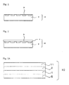
- the heat ray shielding material 10 has, as shown in Fig. 1 , a metal particles-containing layer 2 that contains at least one type of metal particles and where tabular metal particles 3 are eccentrically located in the surface of the layer. Also mentioned is an embodiment as shown in Fig. 2 , where the material has a metal particles-containing layer 2 and an overcoat layer 4 on the metal particles-containing layer and where tabular metal particles 3 are eccentrically located in the surface of the metal particles-containing layer.
- Fig. 3A where the material has a substrate 1, a metal particles-containing layer 2 on the substrate and an adhesive layer 11 on the metal particles-containing layer, and has a hard coat layer 5 on the back of the substrate 1.
- Fig. 3B where the material has a substrate 1, a metal particles-containing layer 2 on the substrate, an overcoat layer 4 on the metal particles-containing layer, and an adhesive layer 11 on the overcoat layer, and has a hard coat layer 5 on the back of the substrate 1.
- the metal particles-containing layer is a layer that contains at least one type of metal particles, and may be suitably selected in accordance with the intended object thereof with no limitation, so far as the metal particles therein contain hexagonal to circular, tabular metal particles in a ratio of at least 60% by number relative to the total number of the metal particles, the main plane of the hexagonal to circular, tabular metal particles is in plane orientation in a range of from 0° to ⁇ 30° on average relative to one surface of the metal particles-containing layer, and at least 80% by number of the hexagonal to circular, tabular metal particles exist in the range of from the surface to d/2, of the metal particles-containing layer where d indicates the thickness of the metal particles-containing layer.
- the heat ray shielding material of the invention is not limited to one produced according to the production method mentioned below; however, the tabular metal particles may be eccentrically located in one surface of the metal particles-containing layer by adding a specific polymer (preferably a latex) thereto in forming the metal particles-containing layer.
- a specific polymer preferably a latex
- the metal particles may be suitably selected in accordance with the intended object thereof so far as they contain hexagonal to circular, tabular metal particles in a ratio of at least 60% by number relative to the total number of the metal particles, in which the main plane of the hexagonal to circular, tabular metal particles is in plane orientation in a range of from 0° to ⁇ 30° on average relative to one surface of the metal particles-containing layer, and at least 80% by number of the hexagonal to circular, tabular metal particles exist in the range of from the surface to d/2, of the metal particles-containing layer where d indicates the thickness of the metal particles-containing layer.
- at least 80% by number of the hexagonal to circular, tabular metal particles exist in the range of from the surface to d/3, of the metal particles-containing layer where d indicates the thickness of the metal particles-containing layer.
- the tabular metal particles are plane-oriented in a range of from 0° to ⁇ 30° on average relative to one surface of the metal particles-containing layer (in case where the heat ray shielding material of the invention has a substrate, relative to the surface of the substrate).
- one surface of the metal particles-containing layer is a flat surface.
- the metal particles-containing layer of the heat ray shielding material of the invention has a substrate serving as a temporary support, it is desirable that both the surface of the metal particles-containing layer and the surface of the substrate are nearly horizontal surfaces.
- the heat ray shielding material may have or may not have the temporary support.
- the size of the metal particles may be suitably selected in accordance with the intended object thereof.
- the particles may have a mean particle diameter of at most 500 nm.
- the material of the metal particles may be suitably selected in accordance with the intended object thereof.
- the heat ray (near-IR ray) reflectance thereof is high, preferred are silver, gold, aluminium, copper, rhodium, nickel, platinum, etc.
- the tabular metal particles may be suitably selected in accordance with the intended object thereof so far as they are particles each comprising two main planes (see Fig. 4A and Fig. 4B ).
- hexagonal, circular, triangular forms, etc. Of those, more preferred are hexagonal or more polygonal to circular forms from the viewpoint of high visible light transmittance thereof. More preferred is a hexagonal or circular form.
- the circular form means such a form that, in the metal tabular particles to be mentioned below, the number of the sides thereof having a length of at most 50% of the mean circle-equivalent diameter is 0 (zero) per one tabular metal particle.
- the circular tabular metal particles are not specifically defined and may be suitably selected in accordance with the intended object thereof, so far as the particles have, when they are observed from the top of the main plane thereof with a transmission electronic microscope (TEM), no angle but have a roundish form.
- TEM transmission electronic microscope
- the hexagonal form means such a form that, in the metal tabular particles to be mentioned below, the number of the sides thereof having a length of at most 20% of the mean circle-equivalent diameter is 6 per one tabular metal particle.
- the hexagonal tabular metal particles are not specifically defined and may be suitably selected in accordance with the intended object thereof, so far as the particles have, when they are observed from the top of the main plane thereof with a transmission electronic microscope (TEM), have a nearly hexagonal form.
- the angle of the hexagonal form of the particles may be an acute angle or a blunt angle. However, from the viewpoint of the ability of the particles to reduce visible light absorption, the angle is preferably a blunt angle.
- the degree of the bluntness of the angle is not specifically defined and may be suitably selected in accordance with the intended object thereof.
- the tabular metal particles may be the same as that of the above-mentioned metal particles and may be suitably selected in accordance with the intended object thereof.
- the tabular metal particles contain at least silver.
- the ratio of the hexagonal to circular, tabular metal particles is at least 60% by number to the total number of the metal particles, preferably at least 65% by number, more preferably at least 70% by number. When the ratio of the tabular metal particles is less than 60% by number, then the visible light transmittance of the layer would lower.
- the main plane of the hexagonal to circular, tabular metal particles is plane-oriented in a range of from 0° to ⁇ 30° on average relative to one surface of the metal particles-containing layer (in case where the heat ray shielding material has a substrate, relative to the surface of the substrate), more preferably in a range of from 0° to ⁇ 20° on average, even more preferably in a range of from 0° to ⁇ 5° on average.
- the existence condition of the tabular metal particles may be suitably selected in accordance with the intended object thereof, but preferably, the particles are aligned as in Fig. 5B or Fig. 5C to be mentioned hereinunder.
- Fig. 5A to Fig. 5E each are a schematic cross-sectional view showing the existence condition of the metal particles-containing layer that contains tabular metal particles in the heat ray shielding material of the invention.
- Fig. 5A, Fig. 5B and Fig. 5C each show the existence condition of the tabular metal particles 3 in the metal particles-containing layer 2.
- Fig. 5D is a view explaining the angle ( ⁇ ) between the plane of the substrate 1 and the plane of the tabular metal particle 3.
- Fig. 5E shows the existence region in the depth direction of the heat ray shielding material of the metal particles-containing layer 2.
- the angle ( ⁇ ) between the surface of the substrate 1 and the main plane or the extended line of the main plane of the tabular metal particle 3 corresponds to the predetermined range in the above-mentioned plane orientation.
- the plane orientation means that the inclined angle ( ⁇ ) shown in Fig. 5D is small when the cross section of the heat ray shielding material is observed, and in particular as in Fig. 5B , means that the surface of the substrate 1 is kept in contact with the main plane of the tabular metal particles 3, or that is, ⁇ is 0°.
- the angle of the plane orientation of the main plane of the tabular metal particle 3 relative to the surface of the substrate 1, or that is, ⁇ shown in Fig. 5D is more than ⁇ 30°, then the reflectance at a predetermined wavelength (for example, from the visible wavelength side to the near-IR region) of the heat ray shielding material may lower.
- the mode of evaluation of whether or not the main plane of the tabular metal particle is in plane orientation relative to one surface of the metal particles-containing layer may be suitably selected in accordance with the object thereof.
- a suitable cross-sectional slice of the heat ray shielding material is prepared, and the metal particles-containing layer (in case where the heat ray shielding material has a substrate, the substrate) and the tabular metal particles in the slice are observed and evaluated.
- the heat ray shielding material is cut with a microtome or through focused ion beam technology (FIB) to prepare a cross-sectional sample or a cross-sectional slice sample, and this is observed with various types of microscopes (for example, field emission scanning electron microscope (FE-SEM) or the like, and the resulting image is analyzed for the intended evaluation.
- FIB focused ion beam technology
- the sample thereof that has been frozen with liquid nitrogen may be cut with a diamond cutter mounted on a microtome to give the cross-sectional sample or the cross-sectional slice sample.
- the binder to cover the tabular metal particles in the heat ray shielding material does not swell in water, the intended cross-sectional sample or cross-sectional slice sample may be directly prepared from the material.
- the cross-sectional sample or the cross-sectional slice sample prepared in the manner as above may be observed in any manner suitably selected in accordance with the intended object thereof so far as in the sample, it is possible to confirm whether or not the main plane of the tabular metal particles could be in plane orientation relative to one surface of the metal particles-containing layer (in case where the heat ray shielding material has a substrate, the surface of the substrate).
- the cross-sectional sample may be observed with FE-SEM, and the cross-sectional slice sample may be observed with TEM.
- the microscope has a spatial resolving power capable of clearly determining the form of the tabular metal particles and the tilt angle ( ⁇ in Fig. 5D ) thereof.
- the mean particle diameter (mean circle-equivalent diameter) of the tabular metal particles may be suitably selected in accordance with the intended object thereof.
- the mean particle diameter is from 70 nm to 500 nm, more preferably from 100 nm to 400 nm.
- the mean particle diameter is less than 70 nm, then the contribution of absorption by the tabular metal particles would be larger than that of reflection by the particles and therefore, the material could not secure sufficient heat ray reflectance; but when more than 500 nm, then the haze (scattering) would increase so that the transparency of the substrate would be thereby lowered.
- the mean particle diameter means the mean value of the data of the main plane diameter (maximum length) of 200 tabular particles that are randomly selected on the image taken in observation of the image with TEM.
- the metal particles-containing layer may contain two or more different types of metal particles that differ in the mean particle diameter (mean circle-equivalent diameter) thereof; and in such a case, the metal particles may have two or more peaks of the mean particle diameter (mean circle-equivalent diameter) thereof, or that is, the metal particles may have two or more mean particle diameters (mean circle-equivalent diameters).
- the coefficient of variation of the particle size distribution of the tabular metal particles is at most 30%, more preferably at most 20%.
- the coefficient of variation is more than 30%, then the heat ray reflection wavelength range of the heat ray shielding material may broaden.
- the coefficient of variation of the particle size distribution of the tabular metal particles is a value (%) calculated, for example, as follows:
- the distribution range of the particle diameter of 200 tabular metal particles that have been employed for calculation of the mean value as described above is plotted to determine the standard deviation of the particle size distribution, and this is divided by the mean value of the main plane diameter (maximum length) obtained as above (mean particle diameter (mean circle-equivalent diameter)) to give the intended value (%).
- the aspect ratio of the tabular metal particles may be suitably selected in accordance with the intended object thereof, and is preferably from 8 to 40, more preferably from 10 to 35 from the viewpoint that the reflectance of the particles in an IR region of from a wavelength 800 nm to a wavelength 1,800 nm could be high.
- the aspect ratio is less than 8, then the reflection wavelength would be shorter than 800 nm; and when more than 40, then the reflection wavelength would be longer than 1,800 nm and the material could not secure a sufficient heat ray reflective power.
- the aspect ratio means a value calculated by dividing the mean particle diameter (mean circle-equivalent diameter of the tabular metal particles by the mean particle thickness of the tabular metal particles.
- the mean particle thickness corresponds to the distance between the main planes of the tabular metal particles; and for example, as shown in Fig. 4A and Fig. 4B , the mean particle thickness may be measured with an atomic force microscope (AFM).
- AFM atomic force microscope
- the method of measuring the mean particle thickness with AFM may be suitably selected in accordance with the intended object thereof. For example, there is mentioned a method where a dispersion of particles that contains tabular metal particles is dropped onto a glass substrate and dried thereon, and the thickness of one particle is measured.
- the thickness of the tabular metal particles is preferably from 5 to 20 nm.
- the heat ray shielding material of the invention at least 80% by number of the hexagonal to circular, tabular metal particles exist in the range of from the surface to d/2, of the metal particles-containing layer, preferably in the range to d/3; and more preferably, at least 60% by number of the hexagonal to circular, tabular metal particles are exposed out of one surface of the metal particles-containing layer.
- the tabular metal particles existing in the range of from the surface to d/2, of the metal particles-containing layer means that at least a part of the tabular metal particles are contained in the range of from the surface to d/2, of the metal particles-containing layer. In other words, the tabular metal particles that partly protrude out of the surface of the metal particles-containing layer, as in Fig.
- Fig. 5C are also in the scope of the concept of the tabular metal particles existing in the range of from the surface to d/2, of the metal particles-containing layer.
- Fig. 5C means that only a part of each tabular metal particle is buried in the metal particles-containing layer in the thickness direction thereof but does not mean that each tabular metal particle is laid on the surface of the metal particles-containing layer.
- the tabular metal particles that are exposed out of one surface of the metal particles-containing layer mean that a part of one surface of the tabular metal particle protrudes out of the surface of the metal particles-containing layer.
- the existence distribution of the tabular metal particles in the metal particles-containing layer may be determined, for example, on the image taken through SEM observation of a cross-sectional sample of the heat ray shielding material.
- the plasmon resonance wavelength ⁇ of the metal that constitutes the tabular metal particles in the metal particles-containing layer may be suitably selected in accordance with the intended object thereof, but from the viewpoint of imparting heat ray reflection performance to the layer, the wavelength is preferably from 400 nm to 2,500 nm, and from the viewpoint of imparting visible light transmittance thereto, the wavelength is more preferably from 700 nm to 2,500 nm.
- the medium in the metal particles-containing layer may be suitably selected in accordance with the intended object thereof.
- the metal-containing layer contains a polymer.
- the polymer includes various high-molecular substances, for example, polyvinyl acetal resin, polyvinyl alcohol resin, polyvinyl butyral resin, polyacrylate resin, polymethyl methacrylate resin, polycarbonate resin, polyvinyl chloride resin, (saturated) polyester resin, polyurethane resin, natural polymers such as gelatin, cellulose, etc.
- the main polymer of the polymer is a polyvinyl alcohol resin, a polyvinyl butyral resin, a polyvinyl chloride resin, a (saturated) polyester resin or a polyurethane resin. More preferred are a polyester resin and a polyurethane resin from the viewpoint that at least 80% by number of the hexagonal to circular, tabular metal particles could be readily made to exist in the range of from the surface to d/2, of the metal particles-containing layer; and even more preferred is a polyester resin from the viewpoint of improving the rubbing resistance of the heat ray shielding material of the invention.
- the main polymer of the polymer contained in the metal-containing layer means the polymer component that accounts for at least 50% by mass of the polymer contained in the metal-containing layer.
- the refractive index n of the medium is preferably from 1.4 to 1.7.
- the heat ray shielding material of the invention in which the thickness of the hexagonal to circular, tabular metal particles is referred to as a, at least 80% by number of the hexagonal to circular, tabular metal particles are covered with the polymer in the range of at least a/10 in the thickness direction thereof, more preferably covered with the polymer in the range of from a/10 to 10a in the thickness direction thereof, even more preferably covered with the polymer in the range of from a/8 to 4a.
- the metal particles when at least a predetermined proportion of the hexagonal to circular, tabular metal particles are buried in the metal particles-containing layer in the manner as above, then the rubbing resistance of the layer could be further more enhanced.
- the embodiment of Fig. 5B is preferred to the embodiment of Fig. 5C .
- the areal ratio [(B/A) x 100] that is the ratio of the total area B of the tabular metal particles to the area A of the substrate when the heat ray shielding material is seen from the top thereof (the total projected area A of the metal particles-containing layer when the metal particles-containing layer is seen in the vertical direction thereof) is preferably at least 15%, more preferably at least 20%.
- the areal ratio is less than 15%, then the maximum heat ray reflectance of the material may lower and the material could not sufficiently secure the heat shielding effect thereof.
- the areal ratio may be determined, for example, by processing the image taken through SEM observation of the substrate of the heat ray shielding material from the top thereof or the image taken through AFM (atomic force microscope) observation thereof.
- the mean intergranular distance of the tabular metal particles that are adjacent to each other in the horizontal direction in the metal particles-containing layer is preferably at least 1/10 of the mean particle diameter of the tabular metal particles from the viewpoint of the visible light transmittance and the maximum heat ray reflectance of the layer.
- the mean intergranular distance in the horizontal direction of the tabular metal particles is less than 1/10 of mean particle diameter of the tabular metal particles, then the maximum heat ray reflectance of the layer may lower.
- the mean intergranular distance in the horizontal direction is preferably at random from the viewpoint of the visible light transmittance of the layer. When the distance is not at random, or that is, when the distance is uniform, there may occur visible light absorption and the visible light transmittance may be thereby lowered.
- the mean intergranular distance in the horizontal direction of the tabular metal particles means a mean value of the intragranular distance data of two adjacent particles.
- the mean intergranular distance that is at random means that "when a SEM image containing at least 100 tabular metal particles is binarized to provide a two-dimensional autocorrelation of the brightness value, then the result does not have any other significant maximum point than the point of origin".
- the tabular metal particles are arranged in the form of the metal particles-containing layer that contains the tabular metal particles, as in Fig. 5A to Fig. 5E .
- the metal particles-containing layer may be composed of a single layer as in Fig. 5A to Fig. 5E , or may be composed of multiple metal particles-containing layers.
- the metal particles-containing layer may be given any desired heat shieldability in accordance with the wavelength range in which the heat shieldability is desired to be given to the layer.
- the metal particles-containing layer is composed of multiple layers, it is necessary that, at least in the outermost metal particles-containing layer in the heat ray shielding material of the invention, at least 80% by number of the hexagonal to circular, tabular metal particles exist in the range of from the surface to d'/2, of the outermost metal particles-containing layer, in which d' indicates the thickness of the outermost metal particles-containing layer.
- the thickness of the metal particles-containing layer is from 10 to 160 nm, more preferably from 20 to 80 nm.
- the thickness d of the metal particles-containing layer is preferably from a to 10a, more preferably from 2a to 8a, in which a indicates the thickness of the hexagonal to circular, tabular metal particles.
- each metal particles-containing layer may be determined, for example, on the image taken through SEM observation of a cross-sectional sample of the heat ray shielding material.
- the boundary between the other layer and the metal particles-containing layer may be determined in the same manner as above, and the thickness d of the metal particles-containing layer may also be determined in the same manner as above.
- the boundary between the metal particles-containing layer and the coating film could be determined on the image taken through SEM observation, and the thickness d of the metal particles-containing layer could be thereby determined.
- the method for synthesizing the tabular metal particles may be suitably selected in accordance with the intended object thereof so far as the intended hexagonal to circular, tabular metal particles could be synthesized in the method.
- a liquid-phase method such as a chemical reduction method, an optochemical reduction method, an electrochemical reduction method or the like.
- a liquid-phase method such as a chemical reduction method, an optochemical reduction method or the like, from the viewpoint of the form and size controllability thereof.
- the particles may be etched with a dissolution species capable of dissolving silver, such as nitric acid, sodium nitrite or the like, then aged by heating or the like to thereby blunt the corners of the hexagonal to triangular, tabular metal particles to give the intended hexagonal to circular, tabular metal particles.
- a dissolution species capable of dissolving silver such as nitric acid, sodium nitrite or the like
- a seed crystal may be fixed on the surface a transparent substrate such as film, glass or the like, and then tabular metal particles (for example, Ag) may be crystal-like grown thereon.
- tabular metal particles for example, Ag
- the tabular metal particles may be further processed so as to be given desired characteristics.
- the additional treatment may be suitably selected in accordance with the intended object thereof. For example, there are mentioned formation of a high-refractivity shell layer, addition of various additives such as dispersant, antioxidant, etc.
- the tabular metal particles may be coated with a high-refractivity material having a high visible light transparency for the purpose of further increasing the visible light transparency thereof.
- the high-refractivity material may be suitably selected in accordance with the object thereof.
- the object thereof there are mentioned TiO x , BaTiO 3 , ZnO, SnO 2 , ZrO 2 , NbO x , etc.
- the coating method may be suitably selected in accordance with the intended object thereof.
- employable here is a method of hydrolyzing tetrabutoxytitanium to form a TiO x layer on the surface of the tabular metal particles of silver, as so reported by Langmuir, 2000, Vol. 16, pp. 2731-2735 .
- TiO x is used as a material of the high-refractivity metal oxide layer
- TiO x having a photocatalyst activity may deteriorate the matrix in which the tabular metal particles are to be dispersed, and in such a case, therefore, an SiO 2 layer may be optionally formed in accordance with the intended object thereof, after the TiO x layer has been formed on the tabular metal particles.
- the tabular metal particles may have, as adsorbed thereon, an antioxidant such as mercaptotetrazole, ascorbic acid or the like for the purpose of preventing the metal such as silver constituting the tabular metal particles from being oxidized.
- an oxidation sacrifice layer of Ni or the like may be formed on the surface of the tabular metal particles.
- the particles may be coated with a metal oxide film of SiO 2 or the like.
- a low-molecular-weight dispersant for imparting dispersibility to the tabular metal particles, for example, a low-molecular-weight dispersant, a high-molecular-weight dispersant or the like that contains at least any of N element, S element and P element, such as quaternary ammonium salts, amines or the like may be added to the tabular metal particles.
- the heat ray shielding material of the invention has an adhesive layer.
- the adhesive layer may contain a UV absorbent.
- the material usable for forming the adhesive layer may be suitably selected in accordance with the intended object thereof.
- the material usable for forming the adhesive layer may be suitably selected in accordance with the intended object thereof.
- PVB polyvinyl butyral
- acrylic resin acrylic resin
- styrene/acrylic resin urethane resin
- polyester resin silicone resin
- silicone resin etc.
- One or more of these may be used here either singly or as combined.
- the adhesive layer comprising the material may be formed by coating.
- an antistatic agent such as sodium metabisulfite, sodium metabisulfite, sodium metabisulfite, sodium metabisulfite, sodium metabisulfite, sodium metabisulfite, sodium metabisulfite, sodium metabisulfite, sodium metabisulfite, sodium metabisulfite, sodium metabisulfite, sodium metabisulfite, sodium metabisulfite, sodium metabisulfite, sodium metabisulfite, sodium metabisulfite, sodium metabisulfite, sodium metabisulfite, sodium metabisulfite, sodium metabisulfite, sodium metabisulfite, sodium metabisulfite, sodium metabisulfite, sodium metabisulfite, sodium metabisulfite, sodium metabisulfite, sodium metabisulfite, sodium metabisulfite, sodium metabisulfite, sodium metabisulfite, sodium metabisulfite, sodium metabisulfite, sodium metabisulfite, sodium metabisulfite, sodium metabisulfite
- the thickness of the adhesive layer is from 0.1 ⁇ m to 10 ⁇ m.
- the heat ray shielding material of the invention has a substrate on the side thereof opposite to the side of the surface of the metal particles-containing layer therein in which at least 80% by number of hexagonal to circular, tabular metal particles are located eccentrically.
- the substrate may be any optically transparent substrate, and may be suitably selected in accordance with the intended object thereof.
- the substrate may be any optically transparent substrate, and may be suitably selected in accordance with the intended object thereof.
- a visible light transmittance of at least 70%, preferably at least 80%, and one having a high near-IR transmittance.
- the substrate is not specifically defined in point of the shape, structure, size, material and others thereof, and may be suitably selected in accordance with the intended object thereof.
- the shape may be tabular or the like; the structure may be a single-layer structure or a laminate layer structure; and the size may be suitably selected in accordance with the size of the heat ray shielding material.
- the material of the substrate may be suitably selected in accordance with the intended object thereof.
- films formed of a polyolefin resin such as polyethylene, polypropylene, poly-4-methylpentene-1, polybutene-1, etc.
- a polyester resin such as polyethylene terephthalate, polyethylene naphthalate, etc.
- a polycarbonate resin such as polyvinyl chloride resin, a polyphenylene sulfide resin, a polyether sulfone resin, a polyethylene sulfide resin, a polyphenylene ether resin, a styrene resin, an acrylic resin, a polyamide resin, a polyimide resin, a cellulose resin such as cellulose acetate, etc.
- a polyethylene terephthalate film especially preferred is a polyethylene terephthalate film.
- the thickness of the substrate film may be suitably selected in accordance with the intended use object of the solar shielding film.
- the thickness maybe from 10 ⁇ m to 500 ⁇ m or so, preferably from 12 ⁇ m to 300 ⁇ m, more preferably from 16 ⁇ m to 125 ⁇ m.
- the functional film has a hard coat layer that has a function of hard coatability.
- the hard coat layer may contain metal oxide particles.
- the hard coat layer may be suitably selected in point of the type thereof and the formation method for the layer, in accordance with the intended object thereof.
- thermosetting or thermocurable resins such as acrylic resin, silicone resin, melamine resin, urethane resin, alkyd resin, fluororesin, etc.
- the thickness of the hard coat layer may be suitably selected in accordance with the intended object thereof. Preferably, the thickness is from 1 ⁇ m to 50 ⁇ m.
- Further forming an antireflection layer and/or an antiglare layer on the hard coat layer is preferred, since a functional film having an antireflection property and/or an antiglare property in addition to scratch resistance may be obtained.
- the hard coat layer may contain the above-mentioned metal oxide particles.
- the heat ray shielding material of the invention may have an overcoat layer that is kept in direct contact with the surface of the metal particles-containing layers on which the hexagonal to circular, tabular metal particles are kept exposed out, for the purpose of preventing oxidation and sulfurization of the tabular metal particles therein through mass transfer and for the purpose of imparting scratch resistance to the material.
- the material may have an overcoat layer between the metal particles-containing layer and the UV absorbent layer to be mentioned hereinunder.
- the material may have such an overcoat layer for the purpose of preventing the tabular metal particles from peeling away in the production step to cause contamination, and for the purpose of preventing the configuration of the tabular metal particles being disordered in forming any other layer on the metal particles-containing layer.
- the overcoat layer may contain a UV absorbent.
- the overcoat layer may be suitably selected in accordance with the intended object thereof.
- the layer contains a binder, a mat agent and a surfactant and may optionally contain any other component.
- the binder may be suitably selected in accordance with the intended object thereof.
- thermosetting or thermocurable resins such as acrylic resin, silicone resin, melamine resin, urethane resin, alkyd resin, fluororesin, etc.
- the thickness of the overcoat layer is preferably from 0.01 ⁇ m to 1,000 ⁇ m, more preferably from 0.02 ⁇ m to 500 ⁇ m, even more preferably from 0.1 to 10 ⁇ m, still more preferably from 0.2 to 5 ⁇ m.
- the layer containing a UV absorbent may be suitably selected in accordance with the intended object thereof, and may be an adhesive layer, or a layer between the adhesive layer and the metal particles-containing layer (for example, an overcoat layer or the like). In any case, it is desirable that the UV absorbent is added to the layer to be arranged on the side to be exposed to sunlight relative to the metal particles-containing layer.
- the UV absorbent may be suitably selected in accordance with the intended object thereof.
- benzophenone-type UV absorbent benzotriazole-type UV absorbent, triazine-type UV absorbent, salicylate-type UV absorbent, cyanoacrylate-type UV absorbent, etc.
- benzophenone-type UV absorbent benzotriazole-type UV absorbent
- triazine-type UV absorbent triazine-type UV absorbent
- salicylate-type UV absorbent cyanoacrylate-type UV absorbent, etc.
- cyanoacrylate-type UV absorbent etc.
- One alone or two or more different types of these may be used here either singly or as combined.
- the benzophenone-type UV absorbent may be suitably selected in accordance with the intended object thereof.
- the intended object thereof there are mentioned 2,4-dihydroxy-4-methoxy-5-sulfobenzophenone, etc.
- the benzotriazole-type UV absorbent may be suitably selected in accordance with the intended object thereof.
- 2-(5-chloro-2H-benzotriazol-2-yl)-4-methyl-6-tertbutylphenol (Tinuvin 326) 2-(2-hydroxy-5-methylphenyl)benzotriazole, 2-(2-hydroxy-5-tertiary butylphenyl)benzotriazole, 2-(2-hydroxy-3,5-di-tertiary butylphenyl)-5-chlorobenzotriazole, etc.
- the triazine-type UV absorbent may be suitably selected in accordance with the intended object thereof.
- mono(hydroxyphenyl)triazine compounds there are mentioned mono(hydroxyphenyl)triazine compounds, bis(hydroxyphenyl)triazine compounds, tris(hydroxyphenyl)triazine compounds, etc.
- the mono(hydroxyphenyl)triazine compound includes, for example, 2-[4-[(2-hydroxy-3-dodecyloxypropyl)oxy]-2-hydroxyphenyl]-4,6-bis(2,4-dimethylphenyl)-1,3,5-triazine, 2-[4-[(2-hydroxy-3-tridecyloxypropyl)oxy]-2-hydroxyphenyl]-4,6-bis(2,4-dimethylphenyl)-1,3,5-triazine, 2-(2,4-dihydroxyphenyl)-4,6-bis(2,4-dimethylphenyl)-1,3,5-triazine, 2-(2-hydroxy-4-isooctyloxyphenyl9-4,6-bis(2,4-dimethylphenyl)-1,3,5-triazine, 2-(2-hydroxy-4-dodecyloxyphenyl)-4,6-bis(2,4-dimethylphenyl)-1,3,5-triazine,
- the bis(hydroxyphenyl)triazine compound includes, for example, 2,4-bis(2-hydroxy-4-propyloxyphenyl)-6-(2,4-dimethylphenyl)-1,3,5-triazine, 2,4-bis(2-hydroxy-3-methyl-4-propyloxyphenyl)-6-(4-methylphenyl)-1,3,5-triazine, 2,4-bis(2-hydroxy-3-methyl-4-hexyloxyphenyl)-6-(2,4-dimethylphenyl)-1,3,5-triazine, 2-phenyl-4,6-bis[2-hydroxy-4-[3-(methoxyheptaethoxy)-2-hydroxypropyloxy]phenyl]-1,3,5-triazine, etc.
- the tris(hydroxyphenyl)triazine compound includes, for example, 2,4-bis(2-hydroxy-4-butoxyphenyl)-6-(2,4-dibutoxyphenyl)-1,3,5-triazine, 2,4,6-tris(2-hydroxy-4-octyloxyphenyl)-1,3,5-triazine, 2,4,6-tris[2-hydroxy-4-(3-butoxy-2-hydroxypropyloxy)phenyl]-1,3,5-triazine, 2,4-bis[2-hydroxy-4-[1-(isooctyloxycarbonyl)ethoxy]phenyl]-6-(2,4-dihydroxyphenyl)-1,3,5-triazine, 2,4,6-tris[2-hydroxy-4-[1-(isooctyloxycarbonyl)ethoxy]phenyl]-1,3,5-triazine, 2,4-bis[2-hydroxy-4-[1-(isooctyloxycarbonyl)e
- the salicylate-type UV absorbent may be suitably selected in accordance with the intended object thereof.
- the intended object thereof there are mentioned phenyl salicylate, p-tert-butylphenyl salicylate, p-octylphenyl salicylate, 2-ethylhexyl salicylate, etc.
- the cyanoacrylate-type UV absorbent may be suitably selected in accordance with the intended object thereof.
- the intended object thereof there are mentioned 2-ethylhexyl-2-cyano-3,3-diphenyl acrylate, ethyl-2-cyano-3,3-diphenyl acrylate, etc.
- the binder may be suitably selected in accordance with the intended object thereof, but is preferably one having high visible light transparency and solar transparency.
- acrylic resin polyvinyl butyral, polyvinyl alcohol, etc.
- the binder absorbs heat rays, then the reflection effect of the tabular metal particles may be thereby weakened, and therefore, it is desirable that, for the UV absorbent layer to be formed between a heat ray source and the tabular metal particles, a material not having an absorption in the region of from 450 nm to 1,500 nm is selected and the thickness of the UV absorbent layer is reduced.
- the thickness of the UV absorbent layer is preferably from 0.01 ⁇ m to 1,000 ⁇ m, more preferably from 0.02 ⁇ m to 500 ⁇ m. When the thickness is less than 0.01 ⁇ m, then the UV absorption would be poor; and when more than 1,000 ⁇ m, then the visible light transmittance may lower.
- the content of the UV absorbent layer varies, depending on the UV absorbent layer to be used, and therefore could not be indiscriminately defined.
- the content is suitably so defined as to give a desired UV transmittance to the heat ray shielding material of the invention.
- the UV transmittance is preferably at most 5%, more preferably at most 2%. When the UV transmittance is more than 5%, then the color of the tabular metal particles-containing layer would be changed by the UV ray of sunlight.
- the heat ray shielding material of the invention optionally contains at least one type of metal oxide particles.
- the heat ray shielding material of the invention has the layer containing the metal oxide particles on the side thereof opposite to the side of the surface of the metal particles-containing layer therein in which hexagonal to circular, tabular metal particles of the metal particles-containing layer are exposed.
- the hard coat layer 5 contains metal oxide particles.
- the hard coat layer 5 maybe laminated on the tabular metal particles-containing layer 2 via the substrate 1. As is in Fig.
- the tabular metal particles-containing layer 2 could reflect a part (or optionally all) of the heat rays given thereto may be reflected and the hard coat layer 5 could absorb a part of the heat rays, and as a result, the heat quantity as a total of the heat quantity which the heat ray shielding material directly receives inside it owing to the heat rays not absorbed by the metal oxide particles-containing layer but having run into the heat ray shielding material and the heat quantity absorbed by the metal oxide particles-containing layer of the heat ray shielding material and indirectly transferred to the inside of the heat ray shielding material could be thereby reduced.
- the material for the metal oxide particles may be suitably selected in accordance with the intended object thereof.
- ITO tin-doped indium oxide
- ATO tin-doped antimony oxide
- zinc oxide titanium oxide, indium oxide, tin oxide, antimony oxide, glass ceramics, etc.
- ITO, ATO and zinc oxide as having an excellent heat ray absorbability and capable of producing a heat ray shielding material having a broad-range heat ray absorbability when combined with the tabular silver particles.
- ITO as capable of blocking at least 90% of IR rays of 1,200 nm or longer and having a visible light transmittance of at least 90%.
- the volume-average particle diameter of the primary particles of the metal oxide particles is at most 0.1 ⁇ m in order not to lower the visible light transmittance of the particles.
- the shape of the metal oxide particles may be suitably selected in accordance with the intended object thereof.
- the particles may be spherical, needle-like, tabular or the like ones.
- the content of the metal oxide particles in the metal oxide particles-containing layer may be suitably selected in accordance with the intended object thereof.
- the content is preferably from 0.1 g/m 2 to 20 g/m 2 , more preferably from 0.5 g/m 2 to 10 g/m 2 , even more preferably from 1.0 g/m 2 to 4.0 g/m 2 .
- the content When the content is less than 0.1 g/m 2 , then the amount of sunshine which could be felt on skin may increase; and when more than 20 g/m 2 , then the visible light transmittance of the layer may worsen. On the other hand, when the content is from 1.0 g/m 2 to 4.0 g/m 2 , it is advantageous since the above two problems could be overcome.
- the content of the metal oxide particles in the metal oxide particles-containing layer may be determined, for example, as follows: The TEM image of an ultra-thin section of the heat ray shielding layer and the SEM image of the surface thereof are observed, the number of the metal oxide particles in a given area and the mean particle diameter thereof are measured, and the mass (g) calculated on the basis of the number and the mean particle diameter thereof and the specific gravity of the metal oxide particles is divided by the given area (m 2 ) to give the content.
- the metal oxide fine particles in a given area of the metal oxide particles-containing layer are dissolved out in methanol, and the mass (g) of the metal oxide particles is measured through fluorescent X-ray determination, and is divided by the given area (m 2 ) to give the content.
- the method for producing the heat ray shielding material of the invention may be suitably selected in accordance with the intended object thereof.
- a coating method of forming the above-mentioned metal particles-containing layer, the above-mentioned UV absorbent layer and optionally other layers on the surface of the above-mentioned substrate is mentioned.
- the method for forming the metal particles-containing layer in the invention may be suitably selected in accordance with the intended object thereof.
- a method of applying a dispersion containing the above-mentioned tabular metal particles onto the surface of the under layer such as the above-mentioned substrate by coating with a dip coater, a die coater, a slit coater, a bar coater, a gravure coater or the like, and a method of plane orientation according to an LB membrane method, a self-assembly method, a spray coating method or the like.
- a composition of the metal particles-containing layer as shown in Examples to be given hereinunder is prepared, and then a latex or the like is added thereto in order that at least 80% by number of the above-mentioned hexagonal to circular, tabular metal particles could exist in the range of from the surface of the metal particles-containing layer to d/2 thereof.
- a latex or the like is added thereto in order that at least 80% by number of the above-mentioned hexagonal to circular, tabular metal particles could exist in the range of from the surface of the metal particles-containing layer to d/2 thereof.
- at least 80% by number of the above-mentioned hexagonal to circular, tabular metal particles exist in the range of from the surface of the metal particles-containing layer to d/3 thereof.
- the amount of the latex to be added is not specifically defined.
- the latex is preferably added in an amount of from 1 to 10000% by mass relative to the tabular silver particles.
- the plane orientation of the tabular metal particles may be promoted by pressing with a pressure roller, such as a calender roller, a lamination roller or the like after the coating.
- the overcoat layer is formed by coating.
- the coating method is not specifically defined, for which is employable any known method. For example, there is mentioned a method of coating with a dispersion that contains the above-mentioned UV absorbent by the use of a dip coater, a die coater, a slit coater, a bar coater, a gravure coater or the like.
- the hard coat layer is formed by coating.
- the coating method is not specifically defined, for which is employable any known method. For example, there is mentioned a method of coating with a dispersion that contains the above-mentioned UV absorbent by the use of a dip coater, a die coater, a slit coater, a bar coater, a gravure coater or the like.
- the adhesive layer is formed by coating.
- the adhesive layer may be laminated on the surface of the under layer such as the above-mentioned substrate, the above-mentioned metal particles-containing layer, the above-mentioned UV absorbent layer or the like.
- the coating method is not specifically defined, for which is employable any known method.
- the maximum value of the solar reflectance of the heat ray shielding material of the invention is in a range of from 600 nm to 2,000 nm, (more preferably from 800 nm to 1,800 nm) for increasing the heat ray reflectance of the material.
- the visible light transmittance of the heat ray shielding material of the invention is at least 60%, more preferably at least 70%.
- the visible light transmittance is less than 60%, then the material may cause a trouble in seeing outside objects when used for glass for automobiles or for glass for buildings.
- the UV transmittance of the heat ray shielding material of the invention is at most 5%, more preferably at most 2%.
- the UV transmittance is more than 5%, then the color of the tabular metal particles-containing layer would be changed by the UV ray of sunlight.
- the haze of the heat ray shielding material of the invention is at most 20%.
- the haze is more than 20%, then it would be unfavorable for safety since the material may cause a trouble in seeing outside objects when used, for example, for glass for automobiles or for glass for buildings.
- the film may be stuck to the indoor side of the windowpanes by laminating thereon via an adhesive.
- the reflection layer is made to face as much as possible the sunlight side because the heat generation could be prevented, and therefore it is suitable that an adhesive layer is laminated on the silver nanodisc particles-containing layer and the material is stuck to a windowpane via the adhesive layer.
- an adhesive-containing liquid may be directly applied onto the surface thereof; however, various additives contained in the adhesive as well as the plasticizer and the solvent used may disturb the alignment of the silver nanodisc layer or may deteriorate the silver nanodiscs themselves.
- the production method may be suitably selected in accordance with the intended object thereof.
- a method of sticking the heat ray shielding material as produced in the manner as above to glass or plastic for vehicles such as automobiles or the like, or to glass or plastic for buildings.
- the heat ray shielding material of the invention may be used in any mode of selectively reflecting or absorbing heat rays (near IR rays), and not specifically defined, the mode of using the material may be suitably selected in accordance with the intended object thereof.
- a film or a laminate structure for vehicles a film or a laminate structure for buildings, a film for agricultural use, etc.
- a film or a laminate structure for vehicles and a film or a laminate structure for buildings from the viewpoint of the energy-saving effect thereof.
- the heat rays mean near-IR rays (from 780 nm to 1,800 nm) that are contained in a ratio of about 50% in sunlight.
- the shape uniformity of the Ag tabular particles was confirmed as follows: The observed SEM image was analyzed for the shape of 200 particles extracted arbitrarily thereon. Of those particles, hexagonal to circular tabular metal particles were referred to as A, and atypical particles such as tears-like ones or other polygonal particles less than hexagonal ones were referred to as B. The proportion of the particles A (% by number) was calculated by image analysis.
- the particle diameter of each of those 100 particles A was measured with a digital caliper, and the data were averaged to give a mean value, which is the mean particle diameter (mean circle-equivalent diameter) of the tabular particles A.
- the standard deviation of the particle diameter distribution was divided by the mean particle diameter (mean circle-equivalent diameter) to give the coefficient (%) of variation of the particle size distribution of the tabular particles A.
- the dispersion containing the formed tabular metal particles was dropped onto a glass substrate and dried thereon, and the thickness of one tabular metal particle A was measured with an atomic force microscope (AFM) (Nanocutell, by Seiko Instruments).
- AFM atomic force microscope
- the condition in measurement with AFM was as follows: Using an autodetection sensor in a DFM mode, the measurement range was 5 ⁇ m, the scanning speed was 180 seconds/1 frame, and the data score was 256 x 256.
- the mean value of the obtained data is the mean particle thickness of the tabular particles A.
- the aspect ratio of the tabular particles A was calculated by dividing the mean particle thickness by the mean particle diameter (mean circle-equivalent diameter).
- a coating liquid 1 having the composition shown below was prepared.
- Aqueous dispersion of polyester latex Finetex ES-650 (by DIC, solid concentration 30% by mas) 28.2 parts by mass
- Surfactant A Lupizol A-90 (by NOF, solid content 1% by mass) 12.5 parts by mass
- Surfactant B Naroacty CL-95 (by Sanyo Chemical, solid content 1% by mass) 15.5 parts by mass Silver Tabular Particles Dispersion B1 of Production Example 1 200 parts by mass Water 800 parts by mass
- the coating liquid 1 was applied onto the surface of a PET film (Cosmoshine A4300, by Toyobo, thickness: 75 ⁇ m) in such a manner that the mean thickness thereof after dried could be 0.08 ⁇ m (80 nm). Subsequently, this was heated at 150°C for 10 minutes, dried and solidified to form a metal particles-containing layer, thereby producing a heat ray shielding material of Example 1.
- a PET film Cosmoshine A4300, by Toyobo, thickness: 75 ⁇ m
- the mean thickness of the metal particles-containing layer, after dried, was determined as follows: Using a laser microscope (VK-8510, by Keyence), the thickness of the PET film not coated with the coating liquid 1, and the thickness of the PET film after coated with the coating liquid 1, heated, dried and solidified were measured. The difference between the thickness of the uncoated film and the thickness of the coated film was calculated. The data at 10 points of one sample were averaged to give the mean thickness of the coating layer.
- the heat ray shielding material was buried in an epoxy resin and frozen with liquid nitrogen. This was cut with a razor in the vertical direction to prepare a cross-sectional sample of the heat ray shielding material.
- the vertical cross-sectional sample was observed with a scanning electron microscope (SEM), and 100 tabular metal particles in the view field were analyzed in point of the tilt angle thereof to the horizontal plane of the substrate (corresponding to ⁇ in Fig. 5D ). The found data were averaged to give a mean value of the tilt angle.
- SEM scanning electron microscope
- FIG. 6 the SEM image of the vertical cross-sectional sample of the heat ray shielding material obtained in Example 1 is shown in Fig. 6 . From Fig. 6 , it is known that at least 80% by number of hexagonal to circular, tabular metal particles were buried in the range of from a/8 to 4a in the thickness direction of the metal particles-containing layer where a indicates the thickness of the hexagonal to circular, tabular metal particles.
- the thickness of the metal particles-containing layer was measured, and the distance from the surface of the metal particles-containing layer to each of 100 tabular metal particles in the layer was measured.
- the tabular metal particles exposed out of the surface of the metal particles-containing layer means that at least 60% by area of one surface of the tabular metal particles is on the same level as the surface of the metal particles-containing layer or protrudes out of the surface thereof.
- the transmittance, as measured at a different wavelength in a range of from 380 nm to 780 nm, of the produced heat ray shielding material was corrected by the spectral luminosity factor at the wavelength to be the visible light transmittance of the material.
- the solar reflectance was determined and evaluated from the transmittance of the produced heat ray shielding material, as measured at a different wavelength in a range of from 350 nm to 2,100 nm. For the heat shieldability evaluation, the samples having a higher reflectance are better.
- a cardboard piece of 1 cm 2 was fixed on the rubbing tip of a rubbing tester. In a smooth-surface dish, the sample was clipped at the top and the bottom thereof. At room temperature of 25°C, a load of 300 g was applied to the cardboard piece and the sample was rubbed with the rubbing tip while the rubbing frequency was varied in the test.
- the rubbing condition was as follows:
- the rubbing resistance of the sample was evaluated by the rubbing frequency that had caused film peeling, as follows:
- Example 2 A heat ray shielding material of Example 2 in which the thickness d of the metal particles-containing layer was 80 nm was produced in the same manner as in Example 1, except that, in Example 1, the PET film of Cosmoshine A4300 was changed to Fujipet (by Fujifilm, thickness: 188 ⁇ m) and that the aqueous polyester latex dispersion (Finetex ES-650) in the coating liquid 1 was changed to an aqueous polyurethane latex dispersion (Olester UD-350, by Mitsui Chemical, solid concentration 38%).
- a heat ray shielding material of Comparative Example 1 was produced in the same manner as in Example 1, except that, in Example 1, the surfactant A, the surfactant B and the aqueous polyester latex dispersion were not added to the coating liquid 1 but 200 parts by mass of a surfactant C (W-1 mentioned below: solid content 2% by mass) was added to the coating liquid 1.
- a surfactant C W-1 mentioned below: solid content 2% by mass
- the metal particles-containing layer in the heat ray shielding material of Comparative Example 1 did not contain a polymer, and the thickness thereof d was 100 nm.
- a heat ray shielding material of Comparative Example 2 in which the thickness d of the metal particles-containing layer was 80 nm, was produced in the same manner as in Example 1, except that, in Example 1, 100 parts by mass of gelatin was further added to the coating liquid 1.
- a heat ray shielding material of Comparative Example 4 was produced in the same manner as in Example 2, except that, in Example 2, the surfactant A, the surfactant B and the aqueous polyurethane dispersion were not added to the coating liquid, but 200 parts by mass of the surfactant C (above W-1: solid content 2% by mass) was added thereto.
- the metal particles-containing layer in the heat ray shielding material of Comparative Example 4 did not contain a polymer, and the thickness thereof was 100 nm.
- Example 2 The heat ray shielding materials of Example 2 and Comparative Examples 1 to 4 were evaluated for various characteristics thereof in the same manner as in Example 1. The obtained results are shown in Table 2 below.
- Table 2 Constitution of Heat Ray Shielding Material Evaluation of Heat Ray Shielding Material Tabular Metal Particles Particle Tilt Angle (plane orientation) Thickness d of Metal Particles-Containing Layer
- [nm] Uneven Distribution of Tabular Metal Particles Presence or Absence of Polymer in Metal Particles-Containing Layer Visible Light trans-mittance (%) Heat Shieldability Rubbing Resistance At least 80% by number of tabular metal particles existing in the range from the surface to d/2, of metal particles-containing layer At least 80% by number of tabular metal particles existing in the range from the surface to d/3, of metal particles-containing layer At least 60% by number of tabular metal particles exposed out of one surface of metal particles-containing layer
- Example 1 tabular silver particles dispersion B1 A 80 A A A polyester 70.1 A A A Example
- the heat ray shielding material of the invention is good in point of all the evaluation results of visible light transmittance, heat shieldability (solar reflectance) and rubbing resistance.
- the mechanism of eccentrically locating tabular metal particles in the surface is not as yet sufficiently clarified, it is considered to be important that the metal particles must indispensably be floated in the liquid surface in coating and drying and that the surface tension balance that would vary in drying would have to be kept well.
- Comparative Example 1 the uneven distribution of the tabular metal particles in the metal particles-containing layer does not satisfy the scope of the invention, and it is known that the rubbing resistance of the produced material is not good.
- the surfactant C was further added to the coating liquid for the metal particles-containing layer so that the uneven distribution of the tabular metal particles could not satisfy the scope of the invention. As a result, it is considered that the rubbing resistance of the material would be thereby worsened. In addition, it is considered that too much addition of the surfactant C would lower the surface tension whereby the tabular metal particles could not float on the surface of the metal particles-containing layer.
- the heat ray shielding material of the invention has high visible light transmittance and high solar reflectance, has excellent heat shieldability and has high rubbing resistance, and therefore the alignment of the tabular metal particles therein can be kept good. Accordingly, the heat ray shielding material can be favorably utilized as various members that are required to prevent heat ray transmission, for example, for films and laminate structures for vehicles such as automobiles, buses, etc.; films and laminate structures for buildings, etc.
Landscapes
- Chemical & Material Sciences (AREA)
- Physics & Mathematics (AREA)
- General Physics & Mathematics (AREA)
- Optics & Photonics (AREA)
- Organic Chemistry (AREA)
- Life Sciences & Earth Sciences (AREA)
- Engineering & Computer Science (AREA)
- Chemical Kinetics & Catalysis (AREA)
- General Chemical & Material Sciences (AREA)
- Geochemistry & Mineralogy (AREA)
- Materials Engineering (AREA)
- Composite Materials (AREA)
- Dispersion Chemistry (AREA)
- Health & Medical Sciences (AREA)
- Toxicology (AREA)
- Surface Treatment Of Glass (AREA)
- Optical Filters (AREA)
Abstract
Description
- The present invention relates to a heat ray shielding material having good visible light transmittance, heat shieldability and rubbing resistance.
- In recent years, as one of energy saving measures for reducing carbon dioxide, heat ray shieldability-imparting materials have been developed for windows of vehicles and buildings. From the viewpoint of heat ray shieldability (solar radiation heat acquisition rate), desired are heat reflective types with no reradiation rather than heat absorptive types with indoor reradiation of absorbed light (in an amount of about 1/3 of the absorbed solar energy), for which various proposals have been made.
- As an IR shielding filter, proposed is a filter using Ag tabular particles (see Patent Literature 1). However, since the IR shielding filer described in
Patent Literature 1 is intended to be used in plasma display panels (PDP) and since such Ag tabular particles are not given configuration control, the filter mainly functions as an IR light absorbent in an IR region and could not function as a material that proactively reflects heat rays. Consequently, when the IR shielding filter comprising such Ag tabular particles is used for shielding from direct sunlight, then the IR absorbent filter itself would be warmed to elevate the ambient temperature owing to the heat thereof and therefore its function as an IR shielding material is insufficient. In Examples inPatent Literature 1, a dispersion containing Ag tabular particles is applied onto glass and dried thereon to provide an IR shielding filter; however, the reference says nothing relating to the distribution of the Ag tabular particles in the thickness direction of the dried film, or that is, the reference has no description relating to segregation of silver particles. -
Patent Literature 2 describes a wavelength-selective film using granular silver. InPatent Literature 2, the Ag layer in which granular silver particles are distributed is formed through Ag sputtering and heat treatment; and as inFig. 3 in the reference, many granular silver particles have an atypical form. In addition,Patent Literature 2 has no description relating to segregation of silver particles in the metal particles-containing layer therein; and even though having a disclosure relating to an embodiment of providing an AlN layer above and below the Ag layer by sputtering, the reference does not describe the plane orientation of the granular silver particles in such an embodiment. - On the other hand,
Patent Literature 3 discloses a heat ray shielding material which has tabular metal particles having a hexagonal to circular form in a ratio of at least 60% by number and in which the main plane of the hexagonal to circular, tabular metal particles is plane-oriented in a range of from 0° to ±30° on average relative to one surface of the metal particles-containing layer. However,Patent Literature 3 has no description relating to segregation of particles. In addition, the reference discloses in the drawings therein that, in the coating film in the Example therein, which is formed by redispersing a gelatin dispersion of tabular silver particles in water after centrifugation thereof, followed by adding an aqueous methanol solution containing a specific surfactant thereto, and further followed by applying the resulting coating liquid, tabular silver particles exist in the area from the lower part to the central part of the metal particles-containing layer. -
- Patent Literature 1:
JP-A 2007-178915 - Patent Literature 2: Japanese Patent
3454422 - Patent Literature 3:
JP-A 2009-255032 - Investigations made by the present inventors have revealed a problem that the IR shielding filter described in
Patent Literature 1 is of an IR absorption type, and therefore when it is used for shielding from the heat of sunlight, the IR absorbent itself is warmed to increase the ambient temperature. In addition, when it is stuck to windowpanes, then there occurs another problem that the glass is broken (heat crack) because of the reason that the temperature increase differs between the part on which sunlight shines and the part on which sunlight does no shine. - In
Patent Literature 2, when IR rays are shielded by granular silver, then it is impossible to sharply shield from IR rays since the half-value width of the spectrum is large, or that is, there is a problem in that the film could not fully shield from IR rays on a shortwave side having much sunlight energy. - When tabular silver particles are aligned at random as in
Patent Literature 1, then they merely absorb light; but when the particles are aligned regularly like in the heat shielding material described inPatent Literature 3, they could reflect light and would be therefore advantageous for an IR shielding film. However,Patent Literature 3 discloses a drawing in which tabular silver particles exists in the area from the lower part to the central part of the metal particles-containing layer, but in fact, the present inventors found that, when the heat shieldability of the material disclosed in the reference is desired to be increased, then the film of the silver-containing layer must be much more thinned than that disclosed in the drawing given in the reference, for the purpose of bettering the alignment of the tabular silver particles in the coating film in the Example in the reference. In addition, the inventors have further found that, in case where the film of the silver-containing layer is thinned, there occurs another problem in that the tabular metal particles peel away or the alignment of the particles may be disordered when the metal particles-containing layer is rubbed, even though the plane orientation of the tabular metal particles is kept good in film formation. - The present invention is to solve the above-mentioned problems in the prior art. Specifically, the technical problem to which the present invention is directed is to provide a heat ray shielding material having good visible light transmittance, heat shieldability (solar reflectance) and rubbing resistance.
- For solving the above-mentioned problems, the present inventors have assiduously investigated the existence state of the tabular metal particles in the metal particles-containing layer and, as a result, have found that when the shape of the tabular metal particles and the plane orientation thereof are too much at random, then the heat ray shieldability worsens. In addition, the inventors have further found that, in the constitution in
Patent Literature 3, when the film of the metal particles-containing layer is thinned for increasing the heat ray shieldability, then the tabular metal particles may peel away or the alignment thereof may be disordered owing to the problem of rubbing resistance of the film as described above, and therefore a stable heat shielding function could not be obtained. - Given the situation, the inventors have found that, in the constitution in
Patent Literature 3, when the tabular metal particles are made to exist in a specific range from the surface of the tabular metal particles-containing layer, then a heat ray shielding material can be provided which has good visible light transmittance, heat shieldability (solar reflectance) and rubbing resistance. - The present invention is based on the above-mentioned findings made by the inventors, and the means thereof for solving the above-mentioned problems are as follows:
- [1] A heat ray shielding material having a metal particles-containing layer that contains at least one type of metal particles, in which the metal particles contain tabular metal particles having a hexagonal to circular form in a ratio of at least 60% by number relative to the total number of the metal particles, the main plane of the hexagonal to circular, tabular metal particles is in plane orientation in a range of from 0° to ±30° on average relative to one surface of the metal particles-containing layer, and at least 80% by number of the hexagonal to circular, tabular metal particles exist in the range of from the surface to d/2, of the metal particles-containing layer where d indicates the thickness of the metal particles-containing layer.
- [2] Preferably, in the heat ray shielding material according to [1], the metal-containing layer contains a polymer.
- [3] Preferably, in the heat ray shielding material according to [2], at least 80% by number of the hexagonal to circular, tabular metal particles are covered by the polymer each in a ratio of at least a/10 in the thickness direction thereof where a indicates the thickness of the hexagonal to circular, tabular metal particle.
- [4] The heat ray shielding material according to [2] or [3], wherein the main polymer of the polymer contained in the metal-containing layer is a polyester resin or a polyurethane resin.
- [5] Preferably, in the heat ray shielding material according to any one of [1] to [4], at least 80% by number of the hexagonal to circular, tabular metal particles exist in the range of from the surface to d/3, of the metal particles-containing layer.
- [6] Preferably, in the heat ray shielding material according to any one of [1] to [5], at least 60% by number of the hexagonal to circular, tabular metal particles are exposed out of one surface of the metal particles-containing layer.
- [7] Preferably, in the heat ray shielding material according to any one of [1] to [6], the mean particle diameter of the hexagonal to circular, tabular metal particles is from 70 nm to 500 nm and the aspect ratio (mean particle diameter/mean particle thickness) of the hexagonal to circular, tabular metal particles is from 8 to 40.
- [8] Preferably, in the heat ray shielding material according to any one of [1] to [7], the tabular metal particles contain at least silver.
- [9] Preferably, the heat ray shielding material according to any one of [1] to [8] has a visible light transmittance of at least 70%.
- [10] Preferably, the heat ray shielding material according to any one of [1] to [9] reflects IR rays.
- [11] Preferably, the heat ray shielding material according to any one of [1] to [10] has a substrate on the surface of the side opposite to the surface of the metal particles-containing layer containing at least 80% by number of the hexagonal to circular, tabular metal particles as located eccentrically therein.
- According to the invention, there is provided a heat ray shielding material having good visible light transmittance, heat shieldability (solar reflectance) and rubbing resistance.
-
- [
Fig. 1] Fig. 1 is a schematic view showing one example of the heat ray shielding material of the invention. - [
Fig. 2] Fig. 2 is a schematic view showing another example of the heat ray shielding material of the invention. - [
Fig. 3A] Fig. 3A is a schematic view showing another example of the heat ray shielding material of the invention. - [
Fig. 3B] Fig. 3B is a schematic view showing another example of the heat ray shielding material of the invention. - [
Fig. 4A] Fig. 4A is a schematic perspective view showing one example of the shape of a tabular particle contained in the heat ray shielding material of the invention, and shows a nearly disc-like tabular particle. - [
Fig. 4B] Fig. 4B is a schematic perspective view showing one example of the shape of a tabular particle contained in the heat ray shielding material of the invention, and shows a nearly hexagonal tabular particle. - [
Fig. 5A] Fig. 5A is a schematic cross-sectional view showing one example of the existence condition of a metal particles-containing layer that contains tabular metal particles in the heat ray shielding material of the invention. - [
Fig. 5B] Fig. 5B is a schematic cross-sectional view showing another example of the existence condition of a metal particles-containing layer that contains tabular metal particles in the heat ray shielding material of the invention. - [
Fig. 5C] Fig. 5C is a schematic cross-sectional view showing another example of the existence condition of a metal particles-containing layer that contains tabular metal particles in the heat ray shielding material of the invention. - [
Fig. 5D] Fig. 5D is a schematic cross-sectional view showing the existence condition of a metal particles-containing layer that contains tabular metal particles in the heat ray shielding material of the invention, and explains the angle (θ) between the metal particles-containing layer that contains tabular metal particles (which is parallel to the plane of the substrate) and the main plane (that determines the circle-equivalent diameter D) of the tabular metal particles. - [
Fig. 5E] Fig. 5E is a schematic cross-sectional view showing the existence condition of a metal particles-containing layer that contains tabular metal particles in the heat ray shielding material of the invention, and shows the existence region of the tabular metal particles in the depth direction of the heat ray shielding material in the metal particles-containing layer. - [
Fig. 6] Fig. 6 is a scanning electron microscope (SEM) image of the cross section of a sample cut in the vertical direction of the heat ray shielding material of Example 1. Description of Embodiments - The heat ray shielding material of the invention is described in detail hereinunder.
- The description of the constitutive elements of the invention given hereinunder may be for some typical embodiments of the invention, to which, however, the invention should not be limited. In this description, the numerical range expressed by the wording "a number to another number" means the range that falls between the former number indicating the lower limit of the range and the latter number indicating the upper limit thereof.
- The heat ray shielding material of the invention has a metal particles-containing layer that contains at least one type of metal particles, in which the metal particles contain tabular metal particles having a hexagonal to circular form in a ratio of at least 60% by number relative to the total number of the metal particles, the main plane of the hexagonal to circular, tabular metal particles is in plane orientation in a range of from 0° to ±30° on average relative to one surface of the metal particles-containing layer, and at least 80% by number of the hexagonal to circular, tabular metal particles exist in the range of from the surface to d/2, of the metal particles-containing layer where d indicates the thickness of the metal particles-containing layer.
- In one preferred embodiment thereof, the heat ray shielding material of the invention has a metal particles-containing layer that contains at least one type of metal particles, and optionally has any other layer such as an adhesive layer, a UV absorbent layer, a substrate layer, a metal oxide particles-containing layer, etc.
- Regarding the layer configuration of the heat ray shielding material, there is mentioned an embodiment where the heat
ray shielding material 10 has, as shown inFig. 1 , a metal particles-containinglayer 2 that contains at least one type of metal particles and wheretabular metal particles 3 are eccentrically located in the surface of the layer. Also mentioned is an embodiment as shown inFig. 2 , where the material has a metal particles-containinglayer 2 and anovercoat layer 4 on the metal particles-containing layer and wheretabular metal particles 3 are eccentrically located in the surface of the metal particles-containing layer. - In addition, favorably mentioned is an embodiment as shown in
Fig. 3A , where the material has asubstrate 1, a metal particles-containinglayer 2 on the substrate and anadhesive layer 11 on the metal particles-containing layer, and has ahard coat layer 5 on the back of thesubstrate 1. - Also favorably mentioned is an embodiment as shown in
Fig. 3B , where the material has asubstrate 1, a metal particles-containinglayer 2 on the substrate, anovercoat layer 4 on the metal particles-containing layer, and anadhesive layer 11 on the overcoat layer, and has ahard coat layer 5 on the back of thesubstrate 1. - The metal particles-containing layer is a layer that contains at least one type of metal particles, and may be suitably selected in accordance with the intended object thereof with no limitation, so far as the metal particles therein contain hexagonal to circular, tabular metal particles in a ratio of at least 60% by number relative to the total number of the metal particles, the main plane of the hexagonal to circular, tabular metal particles is in plane orientation in a range of from 0° to ±30° on average relative to one surface of the metal particles-containing layer, and at least 80% by number of the hexagonal to circular, tabular metal particles exist in the range of from the surface to d/2, of the metal particles-containing layer where d indicates the thickness of the metal particles-containing layer.
- Not adhering to any theory, the heat ray shielding material of the invention is not limited to one produced according to the production method mentioned below; however, the tabular metal particles may be eccentrically located in one surface of the metal particles-containing layer by adding a specific polymer (preferably a latex) thereto in forming the metal particles-containing layer.
- Not specifically defined, the metal particles may be suitably selected in accordance with the intended object thereof so far as they contain hexagonal to circular, tabular metal particles in a ratio of at least 60% by number relative to the total number of the metal particles, in which the main plane of the hexagonal to circular, tabular metal particles is in plane orientation in a range of from 0° to ±30° on average relative to one surface of the metal particles-containing layer, and at least 80% by number of the hexagonal to circular, tabular metal particles exist in the range of from the surface to d/2, of the metal particles-containing layer where d indicates the thickness of the metal particles-containing layer. Preferably, at least 80% by number of the hexagonal to circular, tabular metal particles exist in the range of from the surface to d/3, of the metal particles-containing layer where d indicates the thickness of the metal particles-containing layer.
- Regarding the existence form of the hexagonal to circular, tabular metal particles in the metal particles-containing layer, the tabular metal particles are plane-oriented in a range of from 0° to ±30° on average relative to one surface of the metal particles-containing layer (in case where the heat ray shielding material of the invention has a substrate, relative to the surface of the substrate).
- Preferably, one surface of the metal particles-containing layer is a flat surface. In case where the metal particles-containing layer of the heat ray shielding material of the invention has a substrate serving as a temporary support, it is desirable that both the surface of the metal particles-containing layer and the surface of the substrate are nearly horizontal surfaces. Here, the heat ray shielding material may have or may not have the temporary support.
- Not specifically defined, the size of the metal particles may be suitably selected in accordance with the intended object thereof. For example, the particles may have a mean particle diameter of at most 500 nm.
- Also not specifically defined, the material of the metal particles may be suitably selected in accordance with the intended object thereof. From the viewpoint that the heat ray (near-IR ray) reflectance thereof is high, preferred are silver, gold, aluminium, copper, rhodium, nickel, platinum, etc.
- Not specifically defined, the tabular metal particles may be suitably selected in accordance with the intended object thereof so far as they are particles each comprising two main planes (see
Fig. 4A and Fig. 4B ). For example, there are mentioned hexagonal, circular, triangular forms, etc. Of those, more preferred are hexagonal or more polygonal to circular forms from the viewpoint of high visible light transmittance thereof. More preferred is a hexagonal or circular form. - In this description, the circular form means such a form that, in the metal tabular particles to be mentioned below, the number of the sides thereof having a length of at most 50% of the mean circle-equivalent diameter is 0 (zero) per one tabular metal particle. The circular tabular metal particles are not specifically defined and may be suitably selected in accordance with the intended object thereof, so far as the particles have, when they are observed from the top of the main plane thereof with a transmission electronic microscope (TEM), no angle but have a roundish form.
- In this description, the hexagonal form means such a form that, in the metal tabular particles to be mentioned below, the number of the sides thereof having a length of at most 20% of the mean circle-equivalent diameter is 6 per one tabular metal particle. The same shall apply to the other polygonal forms. The hexagonal tabular metal particles are not specifically defined and may be suitably selected in accordance with the intended object thereof, so far as the particles have, when they are observed from the top of the main plane thereof with a transmission electronic microscope (TEM), have a nearly hexagonal form. For example, the angle of the hexagonal form of the particles may be an acute angle or a blunt angle. However, from the viewpoint of the ability of the particles to reduce visible light absorption, the angle is preferably a blunt angle. The degree of the bluntness of the angle is not specifically defined and may be suitably selected in accordance with the intended object thereof.
- Not specifically defined, the tabular metal particles may be the same as that of the above-mentioned metal particles and may be suitably selected in accordance with the intended object thereof. Preferably, the tabular metal particles contain at least silver.
- Of the metal particles existing in the metal particles-containing layer, the ratio of the hexagonal to circular, tabular metal particles is at least 60% by number to the total number of the metal particles, preferably at least 65% by number, more preferably at least 70% by number. When the ratio of the tabular metal particles is less than 60% by number, then the visible light transmittance of the layer would lower.
- Preferably, in the heat ray shielding material of the invention, the main plane of the hexagonal to circular, tabular metal particles is plane-oriented in a range of from 0° to ±30° on average relative to one surface of the metal particles-containing layer (in case where the heat ray shielding material has a substrate, relative to the surface of the substrate), more preferably in a range of from 0° to ±20° on average, even more preferably in a range of from 0° to ±5° on average.
- Not specifically defined, the existence condition of the tabular metal particles may be suitably selected in accordance with the intended object thereof, but preferably, the particles are aligned as in
Fig. 5B or Fig. 5C to be mentioned hereinunder. - Here,
Fig. 5A to Fig. 5E each are a schematic cross-sectional view showing the existence condition of the metal particles-containing layer that contains tabular metal particles in the heat ray shielding material of the invention.Fig. 5A, Fig. 5B and Fig. 5C each show the existence condition of thetabular metal particles 3 in the metal particles-containinglayer 2.Fig. 5D is a view explaining the angle (±θ) between the plane of thesubstrate 1 and the plane of thetabular metal particle 3.Fig. 5E shows the existence region in the depth direction of the heat ray shielding material of the metal particles-containinglayer 2. - In
Fig. 5D , the angle (±θ) between the surface of thesubstrate 1 and the main plane or the extended line of the main plane of thetabular metal particle 3 corresponds to the predetermined range in the above-mentioned plane orientation. Specifically, the plane orientation means that the inclined angle (±θ) shown inFig. 5D is small when the cross section of the heat ray shielding material is observed, and in particular as inFig. 5B , means that the surface of thesubstrate 1 is kept in contact with the main plane of thetabular metal particles 3, or that is, θ is 0°. When the angle of the plane orientation of the main plane of thetabular metal particle 3 relative to the surface of thesubstrate 1, or that is, θ shown inFig. 5D is more than ±30°, then the reflectance at a predetermined wavelength (for example, from the visible wavelength side to the near-IR region) of the heat ray shielding material may lower. - Not specifically defined, the mode of evaluation of whether or not the main plane of the tabular metal particle is in plane orientation relative to one surface of the metal particles-containing layer (in case where the heat ray shielding material has a substrate, the surface of the substrate) may be suitably selected in accordance with the object thereof. For example, in one evaluation method employable here, a suitable cross-sectional slice of the heat ray shielding material is prepared, and the metal particles-containing layer (in case where the heat ray shielding material has a substrate, the substrate) and the tabular metal particles in the slice are observed and evaluated. Concretely, the heat ray shielding material is cut with a microtome or through focused ion beam technology (FIB) to prepare a cross-sectional sample or a cross-sectional slice sample, and this is observed with various types of microscopes (for example, field emission scanning electron microscope (FE-SEM) or the like, and the resulting image is analyzed for the intended evaluation.
- In the heat ray shielding material, in case where the binder to cover the tabular metal particles swells in water, then the sample thereof that has been frozen with liquid nitrogen may be cut with a diamond cutter mounted on a microtome to give the cross-sectional sample or the cross-sectional slice sample. On the other hand, in case where the binder to cover the tabular metal particles in the heat ray shielding material does not swell in water, the intended cross-sectional sample or cross-sectional slice sample may be directly prepared from the material.
- Not specifically defined, the cross-sectional sample or the cross-sectional slice sample prepared in the manner as above may be observed in any manner suitably selected in accordance with the intended object thereof so far as in the sample, it is possible to confirm whether or not the main plane of the tabular metal particles could be in plane orientation relative to one surface of the metal particles-containing layer (in case where the heat ray shielding material has a substrate, the surface of the substrate). For example, there are mentioned observation with FE-SEM, TEM, optical microscope, etc. The cross-sectional sample may be observed with FE-SEM, and the cross-sectional slice sample may be observed with TEM. In evaluation with FE-SEM, it is desirable that the microscope has a spatial resolving power capable of clearly determining the form of the tabular metal particles and the tilt angle (±θ in
Fig. 5D ) thereof. - Not specifically defined, the mean particle diameter (mean circle-equivalent diameter) of the tabular metal particles may be suitably selected in accordance with the intended object thereof. Preferably, the mean particle diameter is from 70 nm to 500 nm, more preferably from 100 nm to 400 nm. When the mean particle diameter is less than 70 nm, then the contribution of absorption by the tabular metal particles would be larger than that of reflection by the particles and therefore, the material could not secure sufficient heat ray reflectance; but when more than 500 nm, then the haze (scattering) would increase so that the transparency of the substrate would be thereby lowered.
- The mean particle diameter (mean circle-equivalent diameter) means the mean value of the data of the main plane diameter (maximum length) of 200 tabular particles that are randomly selected on the image taken in observation of the image with TEM.
- The metal particles-containing layer may contain two or more different types of metal particles that differ in the mean particle diameter (mean circle-equivalent diameter) thereof; and in such a case, the metal particles may have two or more peaks of the mean particle diameter (mean circle-equivalent diameter) thereof, or that is, the metal particles may have two or more mean particle diameters (mean circle-equivalent diameters).
- In the heat ray shielding material of the invention, preferably, the coefficient of variation of the particle size distribution of the tabular metal particles is at most 30%, more preferably at most 20%. When the coefficient of variation is more than 30%, then the heat ray reflection wavelength range of the heat ray shielding material may broaden.
- Here, the coefficient of variation of the particle size distribution of the tabular metal particles is a value (%) calculated, for example, as follows: The distribution range of the particle diameter of 200 tabular metal particles that have been employed for calculation of the mean value as described above is plotted to determine the standard deviation of the particle size distribution, and this is divided by the mean value of the main plane diameter (maximum length) obtained as above (mean particle diameter (mean circle-equivalent diameter)) to give the intended value (%).
- Not specifically defined, the aspect ratio of the tabular metal particles may be suitably selected in accordance with the intended object thereof, and is preferably from 8 to 40, more preferably from 10 to 35 from the viewpoint that the reflectance of the particles in an IR region of from a wavelength 800 nm to a wavelength 1,800 nm could be high. When the aspect ratio is less than 8, then the reflection wavelength would be shorter than 800 nm; and when more than 40, then the reflection wavelength would be longer than 1,800 nm and the material could not secure a sufficient heat ray reflective power.
- The aspect ratio means a value calculated by dividing the mean particle diameter (mean circle-equivalent diameter of the tabular metal particles by the mean particle thickness of the tabular metal particles. The mean particle thickness corresponds to the distance between the main planes of the tabular metal particles; and for example, as shown in
Fig. 4A and Fig. 4B , the mean particle thickness may be measured with an atomic force microscope (AFM). - Not specifically defined, the method of measuring the mean particle thickness with AFM may be suitably selected in accordance with the intended object thereof. For example, there is mentioned a method where a dispersion of particles that contains tabular metal particles is dropped onto a glass substrate and dried thereon, and the thickness of one particle is measured.
- The thickness of the tabular metal particles is preferably from 5 to 20 nm.
- In the heat ray shielding material of the invention, at least 80% by number of the hexagonal to circular, tabular metal particles exist in the range of from the surface to d/2, of the metal particles-containing layer, preferably in the range to d/3; and more preferably, at least 60% by number of the hexagonal to circular, tabular metal particles are exposed out of one surface of the metal particles-containing layer. The tabular metal particles existing in the range of from the surface to d/2, of the metal particles-containing layer means that at least a part of the tabular metal particles are contained in the range of from the surface to d/2, of the metal particles-containing layer. In other words, the tabular metal particles that partly protrude out of the surface of the metal particles-containing layer, as in
Fig. 5C , are also in the scope of the concept of the tabular metal particles existing in the range of from the surface to d/2, of the metal particles-containing layer.Fig. 5C means that only a part of each tabular metal particle is buried in the metal particles-containing layer in the thickness direction thereof but does not mean that each tabular metal particle is laid on the surface of the metal particles-containing layer. - The tabular metal particles that are exposed out of one surface of the metal particles-containing layer mean that a part of one surface of the tabular metal particle protrudes out of the surface of the metal particles-containing layer.
- Here, the existence distribution of the tabular metal particles in the metal particles-containing layer may be determined, for example, on the image taken through SEM observation of a cross-sectional sample of the heat ray shielding material.
- Not specifically defined, the plasmon resonance wavelength λ of the metal that constitutes the tabular metal particles in the metal particles-containing layer may be suitably selected in accordance with the intended object thereof, but from the viewpoint of imparting heat ray reflection performance to the layer, the wavelength is preferably from 400 nm to 2,500 nm, and from the viewpoint of imparting visible light transmittance thereto, the wavelength is more preferably from 700 nm to 2,500 nm.
- Not specifically defined, the medium in the metal particles-containing layer may be suitably selected in accordance with the intended object thereof. Preferably, in the heat ray shielding material of the invention, the metal-containing layer contains a polymer. The polymer includes various high-molecular substances, for example, polyvinyl acetal resin, polyvinyl alcohol resin, polyvinyl butyral resin, polyacrylate resin, polymethyl methacrylate resin, polycarbonate resin, polyvinyl chloride resin, (saturated) polyester resin, polyurethane resin, natural polymers such as gelatin, cellulose, etc. Of those, in the invention, it is desirable that the main polymer of the polymer is a polyvinyl alcohol resin, a polyvinyl butyral resin, a polyvinyl chloride resin, a (saturated) polyester resin or a polyurethane resin. More preferred are a polyester resin and a polyurethane resin from the viewpoint that at least 80% by number of the hexagonal to circular, tabular metal particles could be readily made to exist in the range of from the surface to d/2, of the metal particles-containing layer; and even more preferred is a polyester resin from the viewpoint of improving the rubbing resistance of the heat ray shielding material of the invention.
- In this description, the main polymer of the polymer contained in the metal-containing layer means the polymer component that accounts for at least 50% by mass of the polymer contained in the metal-containing layer.
- The refractive index n of the medium is preferably from 1.4 to 1.7.
- Preferably in the heat ray shielding material of the invention in which the thickness of the hexagonal to circular, tabular metal particles is referred to as a, at least 80% by number of the hexagonal to circular, tabular metal particles are covered with the polymer in the range of at least a/10 in the thickness direction thereof, more preferably covered with the polymer in the range of from a/10 to 10a in the thickness direction thereof, even more preferably covered with the polymer in the range of from a/8 to 4a. In the metal particles, when at least a predetermined proportion of the hexagonal to circular, tabular metal particles are buried in the metal particles-containing layer in the manner as above, then the rubbing resistance of the layer could be further more enhanced. Specifically, of the heat ray shielding material of the invention, the embodiment of
Fig. 5B is preferred to the embodiment ofFig. 5C . - The areal ratio [(B/A) x 100] that is the ratio of the total area B of the tabular metal particles to the area A of the substrate when the heat ray shielding material is seen from the top thereof (the total projected area A of the metal particles-containing layer when the metal particles-containing layer is seen in the vertical direction thereof) is preferably at least 15%, more preferably at least 20%. When the areal ratio is less than 15%, then the maximum heat ray reflectance of the material may lower and the material could not sufficiently secure the heat shielding effect thereof.
- Here, the areal ratio may be determined, for example, by processing the image taken through SEM observation of the substrate of the heat ray shielding material from the top thereof or the image taken through AFM (atomic force microscope) observation thereof.
- The mean intergranular distance of the tabular metal particles that are adjacent to each other in the horizontal direction in the metal particles-containing layer is preferably at least 1/10 of the mean particle diameter of the tabular metal particles from the viewpoint of the visible light transmittance and the maximum heat ray reflectance of the layer.
- When the mean intergranular distance in the horizontal direction of the tabular metal particles is less than 1/10 of mean particle diameter of the tabular metal particles, then the maximum heat ray reflectance of the layer may lower. The mean intergranular distance in the horizontal direction is preferably at random from the viewpoint of the visible light transmittance of the layer. When the distance is not at random, or that is, when the distance is uniform, there may occur visible light absorption and the visible light transmittance may be thereby lowered.
- Here, the mean intergranular distance in the horizontal direction of the tabular metal particles means a mean value of the intragranular distance data of two adjacent particles. The mean intergranular distance that is at random means that "when a SEM image containing at least 100 tabular metal particles is binarized to provide a two-dimensional autocorrelation of the brightness value, then the result does not have any other significant maximum point than the point of origin".
- In the heat ray shielding material of the invention, the tabular metal particles are arranged in the form of the metal particles-containing layer that contains the tabular metal particles, as in
Fig. 5A to Fig. 5E . - The metal particles-containing layer may be composed of a single layer as in
Fig. 5A to Fig. 5E , or may be composed of multiple metal particles-containing layers. In case where the metal particles-containing layer is composed of multiple layers, it may be given any desired heat shieldability in accordance with the wavelength range in which the heat shieldability is desired to be given to the layer. In case where the metal particles-containing layer is composed of multiple layers, it is necessary that, at least in the outermost metal particles-containing layer in the heat ray shielding material of the invention, at least 80% by number of the hexagonal to circular, tabular metal particles exist in the range of from the surface to d'/2, of the outermost metal particles-containing layer, in which d' indicates the thickness of the outermost metal particles-containing layer. - Preferably, the thickness of the metal particles-containing layer is from 10 to 160 nm, more preferably from 20 to 80 nm. The thickness d of the metal particles-containing layer is preferably from a to 10a, more preferably from 2a to 8a, in which a indicates the thickness of the hexagonal to circular, tabular metal particles.
- Here, the thickness of each metal particles-containing layer may be determined, for example, on the image taken through SEM observation of a cross-sectional sample of the heat ray shielding material.
- In case where any other layer, for example, an overcoat layer to be mentioned below is arranged on the metal particles-containing layer of the heat ray shielding material, the boundary between the other layer and the metal particles-containing layer may be determined in the same manner as above, and the thickness d of the metal particles-containing layer may also be determined in the same manner as above. In case where the same type of polymer as that of the polymer contained in the metal particles-containing layer is used to form a coating film on the metal particles-containing layer, in general, the boundary between the metal particles-containing layer and the coating film could be determined on the image taken through SEM observation, and the thickness d of the metal particles-containing layer could be thereby determined.
- Not specifically defined, the method for synthesizing the tabular metal particles may be suitably selected in accordance with the intended object thereof so far as the intended hexagonal to circular, tabular metal particles could be synthesized in the method. For example, there is mentioned a liquid-phase method such as a chemical reduction method, an optochemical reduction method, an electrochemical reduction method or the like. Of those, especially preferred is a liquid-phase method such as a chemical reduction method, an optochemical reduction method or the like, from the viewpoint of the form and size controllability thereof. After hexagonal to triangular, tabular metal particles have been synthesized, the particles may be etched with a dissolution species capable of dissolving silver, such as nitric acid, sodium nitrite or the like, then aged by heating or the like to thereby blunt the corners of the hexagonal to triangular, tabular metal particles to give the intended hexagonal to circular, tabular metal particles.
- Regarding any other method of synthesizing the tabular metal particles than the above, a seed crystal may be fixed on the surface a transparent substrate such as film, glass or the like, and then tabular metal particles (for example, Ag) may be crystal-like grown thereon.
- In the heat ray shielding material of the invention, the tabular metal particles may be further processed so as to be given desired characteristics. Not specifically defined, the additional treatment may be suitably selected in accordance with the intended object thereof. For example, there are mentioned formation of a high-refractivity shell layer, addition of various additives such as dispersant, antioxidant, etc.
- The tabular metal particles may be coated with a high-refractivity material having a high visible light transparency for the purpose of further increasing the visible light transparency thereof.
- Not specifically defined, the high-refractivity material may be suitably selected in accordance with the object thereof. For example, there are mentioned TiOx, BaTiO3, ZnO, SnO2, ZrO2, NbOx, etc.
- Not specifically defined, the coating method may be suitably selected in accordance with the intended object thereof. For example, employable here is a method of hydrolyzing tetrabutoxytitanium to form a TiOx layer on the surface of the tabular metal particles of silver, as so reported by Langmuir, 2000, Vol. 16, pp. 2731-2735.
- In case where a high-refractivity metal oxide layer shell is difficult to form directly on the tabular metal particles, another method may be employable here, in which the tabular metal particles have been synthesized in the manner as mentioned above, then a shell layer of SiO2 or a polymer is suitably formed thereon, and further the above-mentioned metal oxide layer is formed on the shell layer. In case where TiOx is used as a material of the high-refractivity metal oxide layer, TiOx having a photocatalyst activity may deteriorate the matrix in which the tabular metal particles are to be dispersed, and in such a case, therefore, an SiO2 layer may be optionally formed in accordance with the intended object thereof, after the TiOx layer has been formed on the tabular metal particles.
- In the heat ray shielding material of the invention, the tabular metal particles may have, as adsorbed thereon, an antioxidant such as mercaptotetrazole, ascorbic acid or the like for the purpose of preventing the metal such as silver constituting the tabular metal particles from being oxidized. In addition, also for preventing oxidation, an oxidation sacrifice layer of Ni or the like may be formed on the surface of the tabular metal particles. For shielding them from oxygen, the particles may be coated with a metal oxide film of SiO2 or the like.
- For imparting dispersibility to the tabular metal particles, for example, a low-molecular-weight dispersant, a high-molecular-weight dispersant or the like that contains at least any of N element, S element and P element, such as quaternary ammonium salts, amines or the like may be added to the tabular metal particles.
- Preferably, the heat ray shielding material of the invention has an adhesive layer. The adhesive layer may contain a UV absorbent.
- Not specifically defined, the material usable for forming the adhesive layer may be suitably selected in accordance with the intended object thereof. For example, there are mentioned polyvinyl butyral (PVB) resin, acrylic resin, styrene/acrylic resin, urethane resin, polyester resin, silicone resin, etc. One or more of these may be used here either singly or as combined. The adhesive layer comprising the material may be formed by coating.
- Further, an antistatic agent, a lubricant agent, an antiblocking agent or the like may be added to the adhesive layer.
- Preferably, the thickness of the adhesive layer is from 0.1 µm to 10 µm.
- Preferably, the heat ray shielding material of the invention has a substrate on the side thereof opposite to the side of the surface of the metal particles-containing layer therein in which at least 80% by number of hexagonal to circular, tabular metal particles are located eccentrically.
- Not specifically defined, the substrate may be any optically transparent substrate, and may be suitably selected in accordance with the intended object thereof. For example, there are mentioned one having a visible light transmittance of at least 70%, preferably at least 80%, and one having a high near-IR transmittance.
- The substrate is not specifically defined in point of the shape, structure, size, material and others thereof, and may be suitably selected in accordance with the intended object thereof. The shape may be tabular or the like; the structure may be a single-layer structure or a laminate layer structure; and the size may be suitably selected in accordance with the size of the heat ray shielding material.
- Not specifically defined, the material of the substrate may be suitably selected in accordance with the intended object thereof. For example, there are mentioned films formed of a polyolefin resin such as polyethylene, polypropylene, poly-4-methylpentene-1, polybutene-1, etc.; a polyester resin such as polyethylene terephthalate, polyethylene naphthalate, etc.; a polycarbonate resin, a polyvinyl chloride resin, a polyphenylene sulfide resin, a polyether sulfone resin, a polyethylene sulfide resin, a polyphenylene ether resin, a styrene resin, an acrylic resin, a polyamide resin, a polyimide resin, a cellulose resin such as cellulose acetate, etc.; as well as laminate films formed of such films. Of those, especially preferred is a polyethylene terephthalate film.
- Not specifically defined, the thickness of the substrate film may be suitably selected in accordance with the intended use object of the solar shielding film. In general, the thickness maybe from 10 µm to 500 µm or so, preferably from 12 µm to 300 µm, more preferably from 16 µm to 125 µm.
- For imparting scratch resistance thereto, preferably, the functional film has a hard coat layer that has a function of hard coatability. The hard coat layer may contain metal oxide particles.
- Not specifically defined, the hard coat layer may be suitably selected in point of the type thereof and the formation method for the layer, in accordance with the intended object thereof. For example, there are mentioned thermosetting or thermocurable resins such as acrylic resin, silicone resin, melamine resin, urethane resin, alkyd resin, fluororesin, etc. Not specifically defined, the thickness of the hard coat layer may be suitably selected in accordance with the intended object thereof. Preferably, the thickness is from 1 µm to 50 µm. Further forming an antireflection layer and/or an antiglare layer on the hard coat layer is preferred, since a functional film having an antireflection property and/or an antiglare property in addition to scratch resistance may be obtained. The hard coat layer may contain the above-mentioned metal oxide particles.
- The heat ray shielding material of the invention may have an overcoat layer that is kept in direct contact with the surface of the metal particles-containing layers on which the hexagonal to circular, tabular metal particles are kept exposed out, for the purpose of preventing oxidation and sulfurization of the tabular metal particles therein through mass transfer and for the purpose of imparting scratch resistance to the material. The material may have an overcoat layer between the metal particles-containing layer and the UV absorbent layer to be mentioned hereinunder. Especially in case where the tabular metal particles are eccentrically located in the surface of the metal particles-containing layer in the heat ray shielding material of the invention, the material may have such an overcoat layer for the purpose of preventing the tabular metal particles from peeling away in the production step to cause contamination, and for the purpose of preventing the configuration of the tabular metal particles being disordered in forming any other layer on the metal particles-containing layer.
- The overcoat layer may contain a UV absorbent.
- Not specifically defined, the overcoat layer may be suitably selected in accordance with the intended object thereof. For example, the layer contains a binder, a mat agent and a surfactant and may optionally contain any other component.
- Not specifically defined, the binder may be suitably selected in accordance with the intended object thereof. For example, there are mentioned thermosetting or thermocurable resins such as acrylic resin, silicone resin, melamine resin, urethane resin, alkyd resin, fluororesin, etc.
- The thickness of the overcoat layer is preferably from 0.01 µm to 1,000 µm, more preferably from 0.02 µm to 500 µm, even more preferably from 0.1 to 10 µm, still more preferably from 0.2 to 5 µm.
- The layer containing a UV absorbent may be suitably selected in accordance with the intended object thereof, and may be an adhesive layer, or a layer between the adhesive layer and the metal particles-containing layer (for example, an overcoat layer or the like). In any case, it is desirable that the UV absorbent is added to the layer to be arranged on the side to be exposed to sunlight relative to the metal particles-containing layer.
- Not specifically defined, the UV absorbent may be suitably selected in accordance with the intended object thereof. For example, there are mentioned benzophenone-type UV absorbent, benzotriazole-type UV absorbent, triazine-type UV absorbent, salicylate-type UV absorbent, cyanoacrylate-type UV absorbent, etc. One alone or two or more different types of these may be used here either singly or as combined.
- Not specifically defined, the benzophenone-type UV absorbent may be suitably selected in accordance with the intended object thereof. For example, there are mentioned 2,4-dihydroxy-4-methoxy-5-sulfobenzophenone, etc.
- Not specifically defined, the benzotriazole-type UV absorbent may be suitably selected in accordance with the intended object thereof. For example, there are mentioned 2-(5-chloro-2H-benzotriazol-2-yl)-4-methyl-6-tertbutylphenol (Tinuvin 326), 2-(2-hydroxy-5-methylphenyl)benzotriazole, 2-(2-hydroxy-5-tertiary butylphenyl)benzotriazole, 2-(2-hydroxy-3,5-di-tertiary butylphenyl)-5-chlorobenzotriazole, etc.
- Not specifically defined, the triazine-type UV absorbent may be suitably selected in accordance with the intended object thereof. For example, there are mentioned mono(hydroxyphenyl)triazine compounds, bis(hydroxyphenyl)triazine compounds, tris(hydroxyphenyl)triazine compounds, etc.
- The mono(hydroxyphenyl)triazine compound includes, for example, 2-[4-[(2-hydroxy-3-dodecyloxypropyl)oxy]-2-hydroxyphenyl]-4,6-bis(2,4-dimethylphenyl)-1,3,5-triazine, 2-[4-[(2-hydroxy-3-tridecyloxypropyl)oxy]-2-hydroxyphenyl]-4,6-bis(2,4-dimethylphenyl)-1,3,5-triazine, 2-(2,4-dihydroxyphenyl)-4,6-bis(2,4-dimethylphenyl)-1,3,5-triazine, 2-(2-hydroxy-4-isooctyloxyphenyl9-4,6-bis(2,4-dimethylphenyl)-1,3,5-triazine, 2-(2-hydroxy-4-dodecyloxyphenyl)-4,6-bis(2,4-dimethylphenyl)-1,3,5-triazine, etc. The bis(hydroxyphenyl)triazine compound includes, for example, 2,4-bis(2-hydroxy-4-propyloxyphenyl)-6-(2,4-dimethylphenyl)-1,3,5-triazine, 2,4-bis(2-hydroxy-3-methyl-4-propyloxyphenyl)-6-(4-methylphenyl)-1,3,5-triazine, 2,4-bis(2-hydroxy-3-methyl-4-hexyloxyphenyl)-6-(2,4-dimethylphenyl)-1,3,5-triazine, 2-phenyl-4,6-bis[2-hydroxy-4-[3-(methoxyheptaethoxy)-2-hydroxypropyloxy]phenyl]-1,3,5-triazine, etc. The tris(hydroxyphenyl)triazine compound includes, for example, 2,4-bis(2-hydroxy-4-butoxyphenyl)-6-(2,4-dibutoxyphenyl)-1,3,5-triazine, 2,4,6-tris(2-hydroxy-4-octyloxyphenyl)-1,3,5-triazine, 2,4,6-tris[2-hydroxy-4-(3-butoxy-2-hydroxypropyloxy)phenyl]-1,3,5-triazine, 2,4-bis[2-hydroxy-4-[1-(isooctyloxycarbonyl)ethoxy]phenyl]-6-(2,4-dihydroxyphenyl)-1,3,5-triazine, 2,4,6-tris[2-hydroxy-4-[1-(isooctyloxycarbonyl)ethoxy]phenyl]-1,3,5-triazine, 2,4-bis[2-hydroxy-4-[1-(isooctyloxycarbonyl)ethoxy]phenyl]-6-[2,4-bis[1-(isooctyloxycarbonyl)ethoxy]phenyl-1,3,5-triazine, etc.
- Not specifically defined, the salicylate-type UV absorbent may be suitably selected in accordance with the intended object thereof. For example, there are mentioned phenyl salicylate, p-tert-butylphenyl salicylate, p-octylphenyl salicylate, 2-ethylhexyl salicylate, etc.
- Not specifically defined, the cyanoacrylate-type UV absorbent may be suitably selected in accordance with the intended object thereof. For example, there are mentioned 2-ethylhexyl-2-cyano-3,3-diphenyl acrylate, ethyl-2-cyano-3,3-diphenyl acrylate, etc.
- Not specifically defined, the binder may be suitably selected in accordance with the intended object thereof, but is preferably one having high visible light transparency and solar transparency. For example, there are mentioned acrylic resin, polyvinyl butyral, polyvinyl alcohol, etc. When the binder absorbs heat rays, then the reflection effect of the tabular metal particles may be thereby weakened, and therefore, it is desirable that, for the UV absorbent layer to be formed between a heat ray source and the tabular metal particles, a material not having an absorption in the region of from 450 nm to 1,500 nm is selected and the thickness of the UV absorbent layer is reduced.
- The thickness of the UV absorbent layer is preferably from 0.01 µm to 1,000 µm, more preferably from 0.02 µm to 500 µm. When the thickness is less than 0.01 µm, then the UV absorption would be poor; and when more than 1,000 µm, then the visible light transmittance may lower.
- The content of the UV absorbent layer varies, depending on the UV absorbent layer to be used, and therefore could not be indiscriminately defined. Preferably, the content is suitably so defined as to give a desired UV transmittance to the heat ray shielding material of the invention.
- The UV transmittance is preferably at most 5%, more preferably at most 2%. When the UV transmittance is more than 5%, then the color of the tabular metal particles-containing layer would be changed by the UV ray of sunlight.
- For absorbing long-wave IR rays and from the viewpoint of the balance between the heat ray shieldability and the production balance thereof, the heat ray shielding material of the invention optionally contains at least one type of metal oxide particles. Preferably, the heat ray shielding material of the invention has the layer containing the metal oxide particles on the side thereof opposite to the side of the surface of the metal particles-containing layer therein in which hexagonal to circular, tabular metal particles of the metal particles-containing layer are exposed. In this case, as in
Fig. 3A , for example, it is desirable that thehard coat layer 5 contains metal oxide particles. Thehard coat layer 5 maybe laminated on the tabular metal particles-containinglayer 2 via thesubstrate 1. As is inFig. 3A , in case where the heat ray shielding material of the invention is so configured that the tabular metal particles-containinglayer 2 could be on the side to receive heat rays such as solar light, the tabular metal particles-containinglayer 2 could reflect a part (or optionally all) of the heat rays given thereto may be reflected and thehard coat layer 5 could absorb a part of the heat rays, and as a result, the heat quantity as a total of the heat quantity which the heat ray shielding material directly receives inside it owing to the heat rays not absorbed by the metal oxide particles-containing layer but having run into the heat ray shielding material and the heat quantity absorbed by the metal oxide particles-containing layer of the heat ray shielding material and indirectly transferred to the inside of the heat ray shielding material could be thereby reduced. - Not specifically defined, the material for the metal oxide particles may be suitably selected in accordance with the intended object thereof. For example, there are mentioned tin-doped indium oxide (hereinafter abbreviated as "ITO"), tin-doped antimony oxide (hereinafter abbreviated as "ATO"), zinc oxide, titanium oxide, indium oxide, tin oxide, antimony oxide, glass ceramics, etc. Of those, more preferred are ITO, ATO and zinc oxide as having an excellent heat ray absorbability and capable of producing a heat ray shielding material having a broad-range heat ray absorbability when combined with the tabular silver particles. Especially preferred is ITO as capable of blocking at least 90% of IR rays of 1,200 nm or longer and having a visible light transmittance of at least 90%.
- Preferably, the volume-average particle diameter of the primary particles of the metal oxide particles is at most 0.1 µm in order not to lower the visible light transmittance of the particles.
- Not specifically defined, the shape of the metal oxide particles may be suitably selected in accordance with the intended object thereof. For example, the particles may be spherical, needle-like, tabular or the like ones.
- Not specifically defined, the content of the metal oxide particles in the metal oxide particles-containing layer may be suitably selected in accordance with the intended object thereof. For example, the content is preferably from 0.1 g/m2 to 20 g/m2, more preferably from 0.5 g/m2 to 10 g/m2, even more preferably from 1.0 g/m2 to 4.0 g/m2.
- When the content is less than 0.1 g/m2, then the amount of sunshine which could be felt on skin may increase; and when more than 20 g/m2, then the visible light transmittance of the layer may worsen. On the other hand, when the content is from 1.0 g/m2 to 4.0 g/m2, it is advantageous since the above two problems could be overcome.
- The content of the metal oxide particles in the metal oxide particles-containing layer may be determined, for example, as follows: The TEM image of an ultra-thin section of the heat ray shielding layer and the SEM image of the surface thereof are observed, the number of the metal oxide particles in a given area and the mean particle diameter thereof are measured, and the mass (g) calculated on the basis of the number and the mean particle diameter thereof and the specific gravity of the metal oxide particles is divided by the given area (m2) to give the content. In a different way, the metal oxide fine particles in a given area of the metal oxide particles-containing layer are dissolved out in methanol, and the mass (g) of the metal oxide particles is measured through fluorescent X-ray determination, and is divided by the given area (m2) to give the content.
- Not specifically defined, the method for producing the heat ray shielding material of the invention may be suitably selected in accordance with the intended object thereof. For example, there is mentioned a coating method of forming the above-mentioned metal particles-containing layer, the above-mentioned UV absorbent layer and optionally other layers on the surface of the above-mentioned substrate.
- - Not specifically defined, the method for forming the metal particles-containing layer in the invention may be suitably selected in accordance with the intended object thereof. For example, there are mentioned a method of applying a dispersion containing the above-mentioned tabular metal particles onto the surface of the under layer such as the above-mentioned substrate by coating with a dip coater, a die coater, a slit coater, a bar coater, a gravure coater or the like, and a method of plane orientation according to an LB membrane method, a self-assembly method, a spray coating method or the like. In producing the heat ray shielding material of the invention, a composition of the metal particles-containing layer as shown in Examples to be given hereinunder is prepared, and then a latex or the like is added thereto in order that at least 80% by number of the above-mentioned hexagonal to circular, tabular metal particles could exist in the range of from the surface of the metal particles-containing layer to d/2 thereof. Preferably, at least 80% by number of the above-mentioned hexagonal to circular, tabular metal particles exist in the range of from the surface of the metal particles-containing layer to d/3 thereof. The amount of the latex to be added is not specifically defined. For example, the latex is preferably added in an amount of from 1 to 10000% by mass relative to the tabular silver particles.
- If desired, the plane orientation of the tabular metal particles may be promoted by pressing with a pressure roller, such as a calender roller, a lamination roller or the like after the coating.
- Preferably, the overcoat layer is formed by coating. The coating method is not specifically defined, for which is employable any known method. For example, there is mentioned a method of coating with a dispersion that contains the above-mentioned UV absorbent by the use of a dip coater, a die coater, a slit coater, a bar coater, a gravure coater or the like.
- Preferably, the hard coat layer is formed by coating. The coating method is not specifically defined, for which is employable any known method. For example, there is mentioned a method of coating with a dispersion that contains the above-mentioned UV absorbent by the use of a dip coater, a die coater, a slit coater, a bar coater, a gravure coater or the like.
- Preferably, the adhesive layer is formed by coating. For example, the adhesive layer may be laminated on the surface of the under layer such as the above-mentioned substrate, the above-mentioned metal particles-containing layer, the above-mentioned UV absorbent layer or the like. The coating method is not specifically defined, for which is employable any known method.
- Preferably, the maximum value of the solar reflectance of the heat ray shielding material of the invention is in a range of from 600 nm to 2,000 nm, (more preferably from 800 nm to 1,800 nm) for increasing the heat ray reflectance of the material.
- Preferably, the visible light transmittance of the heat ray shielding material of the invention is at least 60%, more preferably at least 70%. When the visible light transmittance is less than 60%, then the material may cause a trouble in seeing outside objects when used for glass for automobiles or for glass for buildings.
- Preferably, the UV transmittance of the heat ray shielding material of the invention is at most 5%, more preferably at most 2%. When the UV transmittance is more than 5%, then the color of the tabular metal particles-containing layer would be changed by the UV ray of sunlight.
- Preferably, the haze of the heat ray shielding material of the invention is at most 20%. When the haze is more than 20%, then it would be unfavorable for safety since the material may cause a trouble in seeing outside objects when used, for example, for glass for automobiles or for glass for buildings.
- In case where the heat ray shielding material film of the invention is used for imparting functionality to existing windowpanes or the like, the film may be stuck to the indoor side of the windowpanes by laminating thereon via an adhesive. In such a case, it is desirable that the reflection layer is made to face as much as possible the sunlight side because the heat generation could be prevented, and therefore it is suitable that an adhesive layer is laminated on the silver nanodisc particles-containing layer and the material is stuck to a windowpane via the adhesive layer.
- In laminating the adhesive layer onto the surface of the silver nanodisc layer, an adhesive-containing liquid may be directly applied onto the surface thereof; however, various additives contained in the adhesive as well as the plasticizer and the solvent used may disturb the alignment of the silver nanodisc layer or may deteriorate the silver nanodiscs themselves. To minimize such troubles, it would be effective to employ dry lamination in which an adhesive is previously applied onto a release film and dried thereon to prepare an adhesive film, and the adhesive surface of the resulting film is laminated to the surface of the silver nanodisc layer of the film of the invention.
- There can be produced a laminate structure by laminating the heat ray shielding material of the invention with any of glass or plastic.
- Not specifically defined, the production method may be suitably selected in accordance with the intended object thereof. There is mentioned a method of sticking the heat ray shielding material as produced in the manner as above to glass or plastic for vehicles such as automobiles or the like, or to glass or plastic for buildings.
- The heat ray shielding material of the invention may be used in any mode of selectively reflecting or absorbing heat rays (near IR rays), and not specifically defined, the mode of using the material may be suitably selected in accordance with the intended object thereof. For example, there are mentioned a film or a laminate structure for vehicles, a film or a laminate structure for buildings, a film for agricultural use, etc. Of those, preferred are a film or a laminate structure for vehicles and a film or a laminate structure for buildings, from the viewpoint of the energy-saving effect thereof.
- In the invention, the heat rays (near-IR rays) mean near-IR rays (from 780 nm to 1,800 nm) that are contained in a ratio of about 50% in sunlight.
- The characteristics of the invention are described more concretely with reference to Examples given below.
- In the following Examples, the material used, its amount and ratio, the details of the treatment and the treatment process may be suitably modified or changed not overstepping the scope of the invention. Accordingly, the scope of the invention should not be limitatively interpreted by the Examples mentioned below.
- 2.5 mL of an aqueous 0.5 g/L polystyrenesulfonic acid solution was added to 50 mL of an aqueous 2.5 mM sodium citrate solution, and heated up to 35°C. 3 mL of an aqueous 10 mM sodium borohydride solution was added to the above solution, and with stirring, 50 mL of an aqueous 0.5 mM silver nitrate solution was added thereto at a rate of 20 mL/min. The resulting solution was stirred for 30 minutes to prepare a seed solution.
- Next, 2 mL of an aqueous 10 mM ascorbic solution was added to 250 mL of the seed solution and heated up to 35°C. With stirring, 79.6 mL of an aqueous 0.5 mM silver nitrate solution was added to the solution at a rate of 10 mL/min.
- Further, the solution was stirred for 30 minutes, and then 71.1 mL of an aqueous 0.35 M potassium hydroquinonesulfonate was added thereto, and 200 g of an aqueous 7 mass% gelatin solution was added thereto. A white precipitate mixture liquid prepared by mixing 107 mL of an aqueous 0.25 M sodium sulfite solution and 107 mL of an aqueous 0.47 M silver nitrate solution was added to the solution. This was stirred until silver could be sufficiently reduced, and 72 mL of an aqueous 0.17 M NaOH solution was added thereto. Thus, a tabular silver particles dispersion A was obtained.
- It was confirmed that hexagonal tabular particles of silver (hereinafter referred to as Ag hexagonal tabular particles) having a mean circle-equivalent diameter of 240 nm were formed in the obtained, tabular silver particles dispersion A. The thickness of the hexagonal tabular particles was measured with an atomic force microscope (Nanocutell, by Seiko Instruments). It was found that tabular particles were formed having a thickness of 8 nm on average and an aspect ratio of 17.5. The results are shown in Table 1.
- 0.5 mL of NaOH was added to 12 mL of the tabular silver particles dispersion A, 18 mL of ion-exchanged water was added thereto, and the resulting mixture was centrifuged in a centrifuge (Kokusan's H-200N, Amble Rotor BN) to precipitate the Ag hexagonal tabular particles. The supernatant after the centrifugation was removed, 2 mL of water was added to the residue so as to redisperse the precipitated, Ag hexagonal tabular particles, thereby preparing a tabular silver particles dispersion B1 of Production Example 1.
- Next, the obtained metal particles were evaluated for the characteristics thereof, as follows. The results are shown in Table 1 below.
- The shape uniformity of the Ag tabular particles was confirmed as follows: The observed SEM image was analyzed for the shape of 200 particles extracted arbitrarily thereon. Of those particles, hexagonal to circular tabular metal particles were referred to as A, and atypical particles such as tears-like ones or other polygonal particles less than hexagonal ones were referred to as B. The proportion of the particles A (% by number) was calculated by image analysis.
- Similarly, the particle diameter of each of those 100 particles A was measured with a digital caliper, and the data were averaged to give a mean value, which is the mean particle diameter (mean circle-equivalent diameter) of the tabular particles A. The standard deviation of the particle diameter distribution was divided by the mean particle diameter (mean circle-equivalent diameter) to give the coefficient (%) of variation of the particle size distribution of the tabular particles A.
- The dispersion containing the formed tabular metal particles was dropped onto a glass substrate and dried thereon, and the thickness of one tabular metal particle A was measured with an atomic force microscope (AFM) (Nanocutell, by Seiko Instruments). The condition in measurement with AFM was as follows: Using an autodetection sensor in a DFM mode, the measurement range was 5 µm, the scanning speed was 180 seconds/1 frame, and the data score was 256 x 256. The mean value of the obtained data is the mean particle thickness of the tabular particles A.
- From the mean particle diameter (mean circle-equivalent diameter) and the mean particle thickness of the tabular metal particles A thus obtained here, the aspect ratio of the tabular particles A was calculated by dividing the mean particle thickness by the mean particle diameter (mean circle-equivalent diameter).
- The obtained silver tabular dispersion was diluted with water, and the transmittance spectrum thereof was measured with a UV-visible light-near IR spectroscope (JASCO's V-670).
[Table 1] Proportion of Tabular Particles to All Metal Particles (% by number) Shape of Metal Particles Proportion of Tabular Particles A to All Metal Particles (% by number) Characteristics of Hexagonal to Circular, Tabular Metal Particles Peak Wavelength of Transmittance Spectrum of Metal Particles Dispersion (nm) Hexagonal to Circular, Tabular Metal Particles, A Atypical Particles or Other Polygonal Particles less than hexagonal ones, B Mean Particle Diameter of Tabular Particles A (nm) Fluctuation Coefficient of Particle Size Distribution of Tabular Particles A (%) Mean Particle Thickness of Tabular Particles A (nm) Aspect Ratio of Tabular Particles A Silver tabular Particles Dispersion B1 93 nearly hexagonal atypical tabular 93 140 7 8 17.5 1010 - A
coating liquid 1 having the composition shown below was prepared. -
Aqueous dispersion of polyester latex: Finetex ES-650 (by DIC, solid concentration 30% by mas) 28.2 parts by mass Surfactant A: Lupizol A-90 (by NOF, solid content 1% by mass)12.5 parts by mass Surfactant B: Naroacty CL-95 (by Sanyo Chemical, solid content 1% by mass)15.5 parts by mass Silver Tabular Particles Dispersion B1 of Production Example 1 200 parts by mass Water 800 parts by mass - Using a wire bar, the
coating liquid 1 was applied onto the surface of a PET film (Cosmoshine A4300, by Toyobo, thickness: 75 µm) in such a manner that the mean thickness thereof after dried could be 0.08 µm (80 nm). Subsequently, this was heated at 150°C for 10 minutes, dried and solidified to form a metal particles-containing layer, thereby producing a heat ray shielding material of Example 1. - The mean thickness of the metal particles-containing layer, after dried, was determined as follows: Using a laser microscope (VK-8510, by Keyence), the thickness of the PET film not coated with the
coating liquid 1, and the thickness of the PET film after coated with thecoating liquid 1, heated, dried and solidified were measured. The difference between the thickness of the uncoated film and the thickness of the coated film was calculated. The data at 10 points of one sample were averaged to give the mean thickness of the coating layer. - Next, the obtained heat ray shielding material was evaluated for various characteristics thereof. The results are shown in Table 2 below.
- The heat ray shielding material was buried in an epoxy resin and frozen with liquid nitrogen. This was cut with a razor in the vertical direction to prepare a cross-sectional sample of the heat ray shielding material. The vertical cross-sectional sample was observed with a scanning electron microscope (SEM), and 100 tabular metal particles in the view field were analyzed in point of the tilt angle thereof to the horizontal plane of the substrate (corresponding to ±θ in
Fig. 5D ). The found data were averaged to give a mean value of the tilt angle. -
- A: The tilt angle was ±30° or less.
- B: The tile angle was more than ±30°
- In addition, the SEM image of the vertical cross-sectional sample of the heat ray shielding material obtained in Example 1 is shown in
Fig. 6 . FromFig. 6 , it is known that at least 80% by number of hexagonal to circular, tabular metal particles were buried in the range of from a/8 to 4a in the thickness direction of the metal particles-containing layer where a indicates the thickness of the hexagonal to circular, tabular metal particles. - On the cross-sectional SEM image, the thickness of the metal particles-containing layer was measured, and the distance from the surface of the metal particles-containing layer to each of 100 tabular metal particles in the layer was measured.
-
- A: The ratio of the tabular metal particles existing in the range of from the surface to d/2, of the metal particles-containing layer is at least 80% by number.
- B: The ratio of the tabular metal particles existing in the range of from the surface to d/2, of the metal particles-containing layer is less than 80% by number.
-
- A: The ratio of the tabular metal particles existing in the range of from the surface to d/3, of the metal particles-containing layer is at least 80% by number.
- B: The ratio of the tabular metal particles existing in the range of from the surface to d/3, of the metal particles-containing layer is less than 80% by number.
-
- A: The ratio of the tabular metal particles exposed out of one surface of the metal particles-containing layer is at least 60% by number.
- B: The ratio of the tabular metal particles exposed out of one surface of the metal particles-containing layer is less than 60% by number.
- The tabular metal particles exposed out of the surface of the metal particles-containing layer means that at least 60% by area of one surface of the tabular metal particles is on the same level as the surface of the metal particles-containing layer or protrudes out of the surface thereof.
- The transmittance, as measured at a different wavelength in a range of from 380 nm to 780 nm, of the produced heat ray shielding material was corrected by the spectral luminosity factor at the wavelength to be the visible light transmittance of the material.
- Based on the description in JIS5759, the solar reflectance was determined and evaluated from the transmittance of the produced heat ray shielding material, as measured at a different wavelength in a range of from 350 nm to 2,100 nm. For the heat shieldability evaluation, the samples having a higher reflectance are better.
-
- A: The reflectance is 20% or more.
- B: The reflectance is from 17% to less than 20%.
- C: The reflectance is from 13% to less than 17%.
- D: The reflectance is less than 13%.
- A cardboard piece of 1 cm2 was fixed on the rubbing tip of a rubbing tester. In a smooth-surface dish, the sample was clipped at the top and the bottom thereof. At room temperature of 25°C, a load of 300 g was applied to the cardboard piece and the sample was rubbed with the rubbing tip while the rubbing frequency was varied in the test. The rubbing condition was as follows:
- Rubbing distance (one way): 5 cm
- Rubbing speed: about 0.5 back-and-forth/second
- After rubbed, the sample was observed. The rubbing resistance of the sample was evaluated by the rubbing frequency that had caused film peeling, as follows:
-
- D: Film peeled in 0 to 3 back-and-forth rubbings.
- C: Film peeled in 3 to 10 back-and-forth rubbings.
- B: Film peeled in 10 to 30 back-and-forth rubbings.
- A: Film did not peel after 30 back-and-forth rubbings.
- A heat ray shielding material of Example 2 in which the thickness d of the metal particles-containing layer was 80 nm was produced in the same manner as in Example 1, except that, in Example 1, the PET film of Cosmoshine A4300 was changed to Fujipet (by Fujifilm, thickness: 188 µm) and that the aqueous polyester latex dispersion (Finetex ES-650) in the
coating liquid 1 was changed to an aqueous polyurethane latex dispersion (Olester UD-350, by Mitsui Chemical, solid concentration 38%). - A heat ray shielding material of Comparative Example 1 was produced in the same manner as in Example 1, except that, in Example 1, the surfactant A, the surfactant B and the aqueous polyester latex dispersion were not added to the
coating liquid 1 but 200 parts by mass of a surfactant C (W-1 mentioned below:solid content 2% by mass) was added to thecoating liquid 1. - The metal particles-containing layer in the heat ray shielding material of Comparative Example 1 did not contain a polymer, and the thickness thereof d was 100 nm.

- A heat ray shielding material of Comparative Example 2, in which the thickness d of the metal particles-containing layer was 80 nm, was produced in the same manner as in Example 1, except that, in Example 1, 100 parts by mass of gelatin was further added to the
coating liquid 1. - It was known that addition of gelatin disturbed the alignment of the metal particles and therefore worsened the plane orientation thereof (see Table 2 given below).
- A heat ray shielding material of Comparative Example 3, in which the thickness d of the metal particles-containing layer was 80 nm, was produced in the same manner as in Example 1, except that, in Example 1, 200 parts by mass of the surfactant C (above W-1:
solid content 2% by mass) was added to thecoating liquid 1. - A heat ray shielding material of Comparative Example 4 was produced in the same manner as in Example 2, except that, in Example 2, the surfactant A, the surfactant B and the aqueous polyurethane dispersion were not added to the coating liquid, but 200 parts by mass of the surfactant C (above W-1:
solid content 2% by mass) was added thereto. - The metal particles-containing layer in the heat ray shielding material of Comparative Example 4 did not contain a polymer, and the thickness thereof was 100 nm.
- The heat ray shielding materials of Example 2 and Comparative Examples 1 to 4 were evaluated for various characteristics thereof in the same manner as in Example 1. The obtained results are shown in Table 2 below.
[Table 2] Constitution of Heat Ray Shielding Material Evaluation of Heat Ray Shielding Material Tabular Metal Particles Particle Tilt Angle (plane orientation) Thickness d of Metal Particles-Containing Layer [nm] Uneven Distribution of Tabular Metal Particles Presence or Absence of Polymer in Metal Particles-Containing Layer Visible Light trans-mittance (%) Heat Shieldability Rubbing Resistance At least 80% by number of tabular metal particles existing in the range from the surface to d/2, of metal particles-containing layer At least 80% by number of tabular metal particles existing in the range from the surface to d/3, of metal particles-containing layer At least 60% by number of tabular metal particles exposed out of one surface of metal particles-containing layer Example 1 tabular silver particles dispersion B1 A 80 A A A polyester 70.1 A A Example 2 tabular silver particles dispersion B1 A 80 A A A polyurethane 70.2 A B Comparative Example 1 tabular silver particles dispersion B1 A 100 B B A none 70.3 B D Comparative Example 2 tabular silver particles dispersion B1 B 80 A A A Gelatin (main polymer) 70.1 D D Comparative Example 3 tabular silver particles dispersion B1 A 80 B B B polyester 70.0 C C Comparative Example 4 tabular silver particles dispersion B1 A 100 B B A none 70.3 B D - From the results in the above Table 2, it is known that the heat ray shielding material of the invention is good in point of all the evaluation results of visible light transmittance, heat shieldability (solar reflectance) and rubbing resistance. Though the mechanism of eccentrically locating tabular metal particles in the surface is not as yet sufficiently clarified, it is considered to be important that the metal particles must indispensably be floated in the liquid surface in coating and drying and that the surface tension balance that would vary in drying would have to be kept well.
- In Comparative Example 1, the uneven distribution of the tabular metal particles in the metal particles-containing layer does not satisfy the scope of the invention, and it is known that the rubbing resistance of the produced material is not good.
- In Comparative Example 2, gelatin was further added to be the main polymer in the coating liquid for the metal particles-containing layer. In this, however, it is known that the heat shieldability (solar reflectance) of the obtained heat ray shielding material lowered and the rubbing resistance thereof also lowered. The reason why the heat sealability of the obtained material lowered would be considered because the alignment of the metal particles would be disordered and the plane orientation thereof would be thereby worsened.
- In Comparative Example 3, the surfactant C was further added to the coating liquid for the metal particles-containing layer so that the uneven distribution of the tabular metal particles could not satisfy the scope of the invention. As a result, it is considered that the rubbing resistance of the material would be thereby worsened. In addition, it is considered that too much addition of the surfactant C would lower the surface tension whereby the tabular metal particles could not float on the surface of the metal particles-containing layer.
- In Comparative Example 4, the uneven distribution of the tabular metal particles in the metal particles-containing layer does not satisfy the scope of the invention, and it is known that the rubbing resistance of the obtained material is poor.
- The heat ray shielding material of the invention has high visible light transmittance and high solar reflectance, has excellent heat shieldability and has high rubbing resistance, and therefore the alignment of the tabular metal particles therein can be kept good. Accordingly, the heat ray shielding material can be favorably utilized as various members that are required to prevent heat ray transmission, for example, for films and laminate structures for vehicles such as automobiles, buses, etc.; films and laminate structures for buildings, etc.
-
- 1
- Substrate
- 2
- Metal Particles-Containing Layer
- 2a
- Surface of Metal Particles-Containing Layer
- 3
- Tabular Metal Particles
- 4
- Overcoat Layer
- 5
- Hard Coat Layer
- 10
- Heat Ray Shielding Material
- 11
- Adhesive Layer
- 20
- Burying Agent
- D
- Diameter
- L
- Thickness
- F(λ)
- Thickness of Particles-Existing Region
Claims (11)
- A heat ray shielding material having a metal particles-containing layer that contains at least one type of metal particles, in which:the metal particles contain tabular metal particles having a hexagonal to circular form in a ratio of at least 60% by number relative to the total number of the metal particles,the main plane of the hexagonal to circular, tabular metal particles is in plane orientation in a range of from 0° to ±30° on average relative to one surface of the metal particles-containing layer, andat least 80% by number of the hexagonal to circular, tabular metal particles exist in the range of from the surface to d/2, of the metal particles-containing layer where d indicates the thickness of the metal particles-containing layer.
- The heat ray shielding material according to Claim 1, wherein the metal-containing layer contains a polymer.
- The heat ray shielding material according to Claim 2, wherein at least 80% by number of the hexagonal to circular, tabular metal particles are covered by the polymer each in a ratio of at least a/10 in the thickness direction thereof where a indicates the thickness of the hexagonal to circular, tabular metal particle.
- The heat ray shielding material according to Claim 2 or 3, wherein the main polymer of the polymer contained in the metal-containing layer is a polyester resin or a polyurethane resin.
- The heat ray shielding material according to any one of Claims 1 to 4, wherein at least 80% by number of the hexagonal to circular, tabular metal particles exist in the range of from the surface to d/3, of the metal particles-containing layer.
- The heat ray shielding material according to any one of Claims 1 to 5, wherein at least 60% by number of the hexagonal to circular, tabular metal particles are exposed out of one surface of the metal particles-containing layer.
- The heat ray shielding material according to any one of Claims 1 to 6, wherein the mean particle diameter of the hexagonal to circular, tabular metal particles is from 70 nm to 500 nm and the aspect ratio of the hexagonal to circular, tabular metal particles:mean particle diameter/mean particle thickness is from 8 to 40.
- The heat ray shielding material according to any one of Claims 1 to 7, wherein the tabular metal particles contain at least silver.
- The heat ray shielding material according to any one of Claims 1 to 8, which has a visible light transmittance of at least 70%.
- The heat ray shielding material according to any one of Claims 1 to 9, which reflects IR rays.
- The heat ray shielding material according to any one of Claims 1 to 10, which has a substrate on the surface of the side opposite to the surface of the metal particles-containing layer containing at least 80% by number of the hexagonal to circular, tabular metal particles as located eccentrically therein.
Applications Claiming Priority (2)
| Application Number | Priority Date | Filing Date | Title |
|---|---|---|---|
| JP2011193975 | 2011-09-06 | ||
| PCT/JP2012/072780 WO2013035802A1 (en) | 2011-09-06 | 2012-09-06 | Heat ray shielding material |
Publications (2)
| Publication Number | Publication Date |
|---|---|
| EP2755065A1 true EP2755065A1 (en) | 2014-07-16 |
| EP2755065A4 EP2755065A4 (en) | 2015-06-10 |
Family
ID=47832242
Family Applications (1)
| Application Number | Title | Priority Date | Filing Date |
|---|---|---|---|
| EP12830109.0A Withdrawn EP2755065A4 (en) | 2011-09-06 | 2012-09-06 | Heat ray shielding material |
Country Status (5)
| Country | Link |
|---|---|
| US (1) | US20140272386A1 (en) |
| EP (1) | EP2755065A4 (en) |
| JP (1) | JP2013068945A (en) |
| CN (1) | CN103782205B (en) |
| WO (1) | WO2013035802A1 (en) |
Cited By (1)
| Publication number | Priority date | Publication date | Assignee | Title |
|---|---|---|---|---|
| EP2759854A4 (en) * | 2011-09-20 | 2015-04-22 | Fujifilm Corp | Heat ray shielding material |
Families Citing this family (10)
| Publication number | Priority date | Publication date | Assignee | Title |
|---|---|---|---|---|
| EP2833173A4 (en) * | 2012-03-29 | 2015-11-25 | Fujifilm Corp | Heat-ray-shielding material and laminated structure |
| JP6063846B2 (en) * | 2013-09-09 | 2017-01-18 | 富士フイルム株式会社 | Electromagnetic wave permeable laminate |
| JP6268838B2 (en) * | 2013-09-13 | 2018-01-31 | 凸版印刷株式会社 | Infrared shielding film and manufacturing method thereof |
| KR102463851B1 (en) * | 2015-06-02 | 2022-11-04 | 스미토모 긴조쿠 고잔 가부시키가이샤 | Metal particle aggregate, metal particle dispersion, heat ray shielding film, heat ray shielding glass, heat ray shielding fine particle dispersion and heat ray shielding laminated transparent substrate |
| JP6602453B2 (en) * | 2016-02-29 | 2019-11-06 | 富士フイルム株式会社 | Ink composition, ink set, image forming method, and printed matter |
| JP6580248B2 (en) * | 2016-02-29 | 2019-09-25 | 富士フイルム株式会社 | Ink composition and image forming method |
| LU100018B1 (en) * | 2017-01-11 | 2018-08-14 | Luxembourg Inst Science & Tech List | Infrared reflective and electrical conductive composite film and manufacturing method thereof |
| DE102019210952B3 (en) * | 2018-08-30 | 2019-11-14 | Ford Global Technologies, Llc | Field of view display system and windshield for a motor vehicle |
| US20220229215A1 (en) * | 2019-05-29 | 2022-07-21 | Nec Corporation | Radiation suppression film and radiation suppression structure |
| JP7679191B2 (en) * | 2020-11-09 | 2025-05-19 | 三星電子株式会社 | Resin film, method for producing resin film, and display device |
Family Cites Families (10)
| Publication number | Priority date | Publication date | Assignee | Title |
|---|---|---|---|---|
| JPS61223703A (en) * | 1985-03-28 | 1986-10-04 | Matsushita Electric Ind Co Ltd | Reflector for infra-red ray |
| JP3454422B2 (en) | 1999-07-16 | 2003-10-06 | セントラル硝子株式会社 | Radio wave transmitting wavelength selective substrate and its manufacturing method |
| US6650478B1 (en) * | 1999-08-20 | 2003-11-18 | Cpfilms Inc. | Optical filter for a window |
| JP4540945B2 (en) * | 2003-06-26 | 2010-09-08 | 住友大阪セメント株式会社 | Coating for forming metal thin film, metal thin film and method for producing the same |
| JP4855040B2 (en) * | 2005-10-14 | 2012-01-18 | 富士フイルム株式会社 | Infrared shielding filter |
| JP4855070B2 (en) | 2005-12-28 | 2012-01-18 | 富士フイルム株式会社 | Metal fine particle dispersion and infrared shielding filter |
| JP2009255032A (en) | 2008-03-27 | 2009-11-05 | Ibiden Co Ltd | Honeycomb structure |
| JP2010085917A (en) * | 2008-10-02 | 2010-04-15 | Asahi Kasei E-Materials Corp | Transparent heat-ray reflecting film and heat-ray shielding windowpane using the same |
| JP5471293B2 (en) * | 2008-10-23 | 2014-04-16 | 三菱化学株式会社 | Heat ray reflective film, laminate thereof and coating solution for forming heat ray reflective layer |
| JP5570305B2 (en) * | 2009-11-06 | 2014-08-13 | 富士フイルム株式会社 | Heat ray shielding material |
-
2012
- 2012-09-06 EP EP12830109.0A patent/EP2755065A4/en not_active Withdrawn
- 2012-09-06 WO PCT/JP2012/072780 patent/WO2013035802A1/en not_active Ceased
- 2012-09-06 JP JP2012196341A patent/JP2013068945A/en active Pending
- 2012-09-06 CN CN201280042976.4A patent/CN103782205B/en not_active Expired - Fee Related
-
2014
- 2014-03-05 US US14/198,120 patent/US20140272386A1/en not_active Abandoned
Cited By (1)
| Publication number | Priority date | Publication date | Assignee | Title |
|---|---|---|---|---|
| EP2759854A4 (en) * | 2011-09-20 | 2015-04-22 | Fujifilm Corp | Heat ray shielding material |
Also Published As
| Publication number | Publication date |
|---|---|
| EP2755065A4 (en) | 2015-06-10 |
| WO2013035802A1 (en) | 2013-03-14 |
| CN103782205B (en) | 2017-02-08 |
| JP2013068945A (en) | 2013-04-18 |
| US20140272386A1 (en) | 2014-09-18 |
| CN103782205A (en) | 2014-05-07 |
Similar Documents
| Publication | Publication Date | Title |
|---|---|---|
| EP2755065A1 (en) | Heat ray shielding material | |
| US9720153B2 (en) | Infrared ray shielding film | |
| EP2759854A1 (en) | Heat ray shielding material | |
| EP2833173A1 (en) | Heat-ray-shielding material and laminated structure | |
| US9971077B2 (en) | Multilayer structure and laminate structure | |
| US20140212655A1 (en) | Heat ray shielding material | |
| JP5709707B2 (en) | Heat ray shielding material | |
| US20130260139A1 (en) | Heat-ray shielding material | |
| JP5636208B2 (en) | Metallic tabular grain-containing composition for heat ray shielding | |
| JP5878059B2 (en) | Infrared shielding film | |
| WO2013146447A1 (en) | Silver-particle containing film and manufacturing method therefor, and heat ray shielding material | |
| JP5922919B2 (en) | Heat ray shielding material and bonded structure | |
| JP5833516B2 (en) | Far-infrared shielding material | |
| WO2014038457A1 (en) | Infrared blocking film | |
| JP2013077007A (en) | Heat-ray shielding material | |
| JP5878050B2 (en) | Heat ray shielding material |
Legal Events
| Date | Code | Title | Description |
|---|---|---|---|
| PUAI | Public reference made under article 153(3) epc to a published international application that has entered the european phase |
Free format text: ORIGINAL CODE: 0009012 |
|
| 17P | Request for examination filed |
Effective date: 20140318 |
|
| AK | Designated contracting states |
Kind code of ref document: A1 Designated state(s): AL AT BE BG CH CY CZ DE DK EE ES FI FR GB GR HR HU IE IS IT LI LT LU LV MC MK MT NL NO PL PT RO RS SE SI SK SM TR |
|
| DAX | Request for extension of the european patent (deleted) | ||
| RA4 | Supplementary search report drawn up and despatched (corrected) |
Effective date: 20150513 |
|
| RIC1 | Information provided on ipc code assigned before grant |
Ipc: C03C 17/32 20060101ALI20150507BHEP Ipc: C03C 17/36 20060101ALI20150507BHEP Ipc: B32B 7/02 20060101ALI20150507BHEP Ipc: G02B 5/26 20060101AFI20150507BHEP |
|
| 17Q | First examination report despatched |
Effective date: 20160126 |
|
| GRAP | Despatch of communication of intention to grant a patent |
Free format text: ORIGINAL CODE: EPIDOSNIGR1 |
|
| INTG | Intention to grant announced |
Effective date: 20180508 |
|
| STAA | Information on the status of an ep patent application or granted ep patent |
Free format text: STATUS: THE APPLICATION IS DEEMED TO BE WITHDRAWN |
|
| 18D | Application deemed to be withdrawn |
Effective date: 20180919 |