EP2754865A1 - Exhaust gas purifying apparatus - Google Patents
Exhaust gas purifying apparatus Download PDFInfo
- Publication number
- EP2754865A1 EP2754865A1 EP11871889.9A EP11871889A EP2754865A1 EP 2754865 A1 EP2754865 A1 EP 2754865A1 EP 11871889 A EP11871889 A EP 11871889A EP 2754865 A1 EP2754865 A1 EP 2754865A1
- Authority
- EP
- European Patent Office
- Prior art keywords
- exhaust
- exhaust gas
- evaporation tube
- connection pipes
- manifold
- Prior art date
- Legal status (The legal status is an assumption and is not a legal conclusion. Google has not performed a legal analysis and makes no representation as to the accuracy of the status listed.)
- Granted
Links
Images

Classifications
-
- F—MECHANICAL ENGINEERING; LIGHTING; HEATING; WEAPONS; BLASTING
- F01—MACHINES OR ENGINES IN GENERAL; ENGINE PLANTS IN GENERAL; STEAM ENGINES
- F01N—GAS-FLOW SILENCERS OR EXHAUST APPARATUS FOR MACHINES OR ENGINES IN GENERAL; GAS-FLOW SILENCERS OR EXHAUST APPARATUS FOR INTERNAL-COMBUSTION ENGINES
- F01N3/00—Exhaust or silencing apparatus having means for purifying, rendering innocuous, or otherwise treating exhaust
- F01N3/08—Exhaust or silencing apparatus having means for purifying, rendering innocuous, or otherwise treating exhaust for rendering innocuous
- F01N3/10—Exhaust or silencing apparatus having means for purifying, rendering innocuous, or otherwise treating exhaust for rendering innocuous by thermal or catalytic conversion of noxious components of exhaust
- F01N3/24—Exhaust or silencing apparatus having means for purifying, rendering innocuous, or otherwise treating exhaust for rendering innocuous by thermal or catalytic conversion of noxious components of exhaust characterised by constructional aspects of converting apparatus
- F01N3/28—Construction of catalytic reactors
- F01N3/2892—Exhaust flow directors or the like, e.g. upstream of catalytic device
-
- F—MECHANICAL ENGINEERING; LIGHTING; HEATING; WEAPONS; BLASTING
- F01—MACHINES OR ENGINES IN GENERAL; ENGINE PLANTS IN GENERAL; STEAM ENGINES
- F01N—GAS-FLOW SILENCERS OR EXHAUST APPARATUS FOR MACHINES OR ENGINES IN GENERAL; GAS-FLOW SILENCERS OR EXHAUST APPARATUS FOR INTERNAL-COMBUSTION ENGINES
- F01N3/00—Exhaust or silencing apparatus having means for purifying, rendering innocuous, or otherwise treating exhaust
- F01N3/08—Exhaust or silencing apparatus having means for purifying, rendering innocuous, or otherwise treating exhaust for rendering innocuous
-
- B—PERFORMING OPERATIONS; TRANSPORTING
- B01—PHYSICAL OR CHEMICAL PROCESSES OR APPARATUS IN GENERAL
- B01D—SEPARATION
- B01D53/00—Separation of gases or vapours; Recovering vapours of volatile solvents from gases; Chemical or biological purification of waste gases, e.g. engine exhaust gases, smoke, fumes, flue gases, aerosols
- B01D53/34—Chemical or biological purification of waste gases
- B01D53/92—Chemical or biological purification of waste gases of engine exhaust gases
- B01D53/94—Chemical or biological purification of waste gases of engine exhaust gases by catalytic processes
-
- F—MECHANICAL ENGINEERING; LIGHTING; HEATING; WEAPONS; BLASTING
- F01—MACHINES OR ENGINES IN GENERAL; ENGINE PLANTS IN GENERAL; STEAM ENGINES
- F01N—GAS-FLOW SILENCERS OR EXHAUST APPARATUS FOR MACHINES OR ENGINES IN GENERAL; GAS-FLOW SILENCERS OR EXHAUST APPARATUS FOR INTERNAL-COMBUSTION ENGINES
- F01N13/00—Exhaust or silencing apparatus characterised by constructional features
- F01N13/08—Other arrangements or adaptations of exhaust conduits
- F01N13/10—Other arrangements or adaptations of exhaust conduits of exhaust manifolds
-
- F—MECHANICAL ENGINEERING; LIGHTING; HEATING; WEAPONS; BLASTING
- F01—MACHINES OR ENGINES IN GENERAL; ENGINE PLANTS IN GENERAL; STEAM ENGINES
- F01N—GAS-FLOW SILENCERS OR EXHAUST APPARATUS FOR MACHINES OR ENGINES IN GENERAL; GAS-FLOW SILENCERS OR EXHAUST APPARATUS FOR INTERNAL-COMBUSTION ENGINES
- F01N3/00—Exhaust or silencing apparatus having means for purifying, rendering innocuous, or otherwise treating exhaust
- F01N3/08—Exhaust or silencing apparatus having means for purifying, rendering innocuous, or otherwise treating exhaust for rendering innocuous
- F01N3/10—Exhaust or silencing apparatus having means for purifying, rendering innocuous, or otherwise treating exhaust for rendering innocuous by thermal or catalytic conversion of noxious components of exhaust
-
- F—MECHANICAL ENGINEERING; LIGHTING; HEATING; WEAPONS; BLASTING
- F01—MACHINES OR ENGINES IN GENERAL; ENGINE PLANTS IN GENERAL; STEAM ENGINES
- F01N—GAS-FLOW SILENCERS OR EXHAUST APPARATUS FOR MACHINES OR ENGINES IN GENERAL; GAS-FLOW SILENCERS OR EXHAUST APPARATUS FOR INTERNAL-COMBUSTION ENGINES
- F01N3/00—Exhaust or silencing apparatus having means for purifying, rendering innocuous, or otherwise treating exhaust
- F01N3/08—Exhaust or silencing apparatus having means for purifying, rendering innocuous, or otherwise treating exhaust for rendering innocuous
- F01N3/10—Exhaust or silencing apparatus having means for purifying, rendering innocuous, or otherwise treating exhaust for rendering innocuous by thermal or catalytic conversion of noxious components of exhaust
- F01N3/18—Exhaust or silencing apparatus having means for purifying, rendering innocuous, or otherwise treating exhaust for rendering innocuous by thermal or catalytic conversion of noxious components of exhaust characterised by methods of operation; Control
- F01N3/20—Exhaust or silencing apparatus having means for purifying, rendering innocuous, or otherwise treating exhaust for rendering innocuous by thermal or catalytic conversion of noxious components of exhaust characterised by methods of operation; Control specially adapted for catalytic conversion
-
- F—MECHANICAL ENGINEERING; LIGHTING; HEATING; WEAPONS; BLASTING
- F01—MACHINES OR ENGINES IN GENERAL; ENGINE PLANTS IN GENERAL; STEAM ENGINES
- F01N—GAS-FLOW SILENCERS OR EXHAUST APPARATUS FOR MACHINES OR ENGINES IN GENERAL; GAS-FLOW SILENCERS OR EXHAUST APPARATUS FOR INTERNAL-COMBUSTION ENGINES
- F01N3/00—Exhaust or silencing apparatus having means for purifying, rendering innocuous, or otherwise treating exhaust
- F01N3/08—Exhaust or silencing apparatus having means for purifying, rendering innocuous, or otherwise treating exhaust for rendering innocuous
- F01N3/10—Exhaust or silencing apparatus having means for purifying, rendering innocuous, or otherwise treating exhaust for rendering innocuous by thermal or catalytic conversion of noxious components of exhaust
- F01N3/18—Exhaust or silencing apparatus having means for purifying, rendering innocuous, or otherwise treating exhaust for rendering innocuous by thermal or catalytic conversion of noxious components of exhaust characterised by methods of operation; Control
- F01N3/20—Exhaust or silencing apparatus having means for purifying, rendering innocuous, or otherwise treating exhaust for rendering innocuous by thermal or catalytic conversion of noxious components of exhaust characterised by methods of operation; Control specially adapted for catalytic conversion
- F01N3/2053—By-passing catalytic reactors, e.g. to prevent overheating
-
- F—MECHANICAL ENGINEERING; LIGHTING; HEATING; WEAPONS; BLASTING
- F01—MACHINES OR ENGINES IN GENERAL; ENGINE PLANTS IN GENERAL; STEAM ENGINES
- F01N—GAS-FLOW SILENCERS OR EXHAUST APPARATUS FOR MACHINES OR ENGINES IN GENERAL; GAS-FLOW SILENCERS OR EXHAUST APPARATUS FOR INTERNAL-COMBUSTION ENGINES
- F01N3/00—Exhaust or silencing apparatus having means for purifying, rendering innocuous, or otherwise treating exhaust
- F01N3/08—Exhaust or silencing apparatus having means for purifying, rendering innocuous, or otherwise treating exhaust for rendering innocuous
- F01N3/10—Exhaust or silencing apparatus having means for purifying, rendering innocuous, or otherwise treating exhaust for rendering innocuous by thermal or catalytic conversion of noxious components of exhaust
- F01N3/18—Exhaust or silencing apparatus having means for purifying, rendering innocuous, or otherwise treating exhaust for rendering innocuous by thermal or catalytic conversion of noxious components of exhaust characterised by methods of operation; Control
- F01N3/20—Exhaust or silencing apparatus having means for purifying, rendering innocuous, or otherwise treating exhaust for rendering innocuous by thermal or catalytic conversion of noxious components of exhaust characterised by methods of operation; Control specially adapted for catalytic conversion
- F01N3/206—Adding periodically or continuously substances to exhaust gases for promoting purification, e.g. catalytic material in liquid form, NOx reducing agents
- F01N3/2066—Selective catalytic reduction [SCR]
-
- F—MECHANICAL ENGINEERING; LIGHTING; HEATING; WEAPONS; BLASTING
- F01—MACHINES OR ENGINES IN GENERAL; ENGINE PLANTS IN GENERAL; STEAM ENGINES
- F01N—GAS-FLOW SILENCERS OR EXHAUST APPARATUS FOR MACHINES OR ENGINES IN GENERAL; GAS-FLOW SILENCERS OR EXHAUST APPARATUS FOR INTERNAL-COMBUSTION ENGINES
- F01N3/00—Exhaust or silencing apparatus having means for purifying, rendering innocuous, or otherwise treating exhaust
- F01N3/08—Exhaust or silencing apparatus having means for purifying, rendering innocuous, or otherwise treating exhaust for rendering innocuous
- F01N3/10—Exhaust or silencing apparatus having means for purifying, rendering innocuous, or otherwise treating exhaust for rendering innocuous by thermal or catalytic conversion of noxious components of exhaust
- F01N3/24—Exhaust or silencing apparatus having means for purifying, rendering innocuous, or otherwise treating exhaust for rendering innocuous by thermal or catalytic conversion of noxious components of exhaust characterised by constructional aspects of converting apparatus
-
- F—MECHANICAL ENGINEERING; LIGHTING; HEATING; WEAPONS; BLASTING
- F01—MACHINES OR ENGINES IN GENERAL; ENGINE PLANTS IN GENERAL; STEAM ENGINES
- F01N—GAS-FLOW SILENCERS OR EXHAUST APPARATUS FOR MACHINES OR ENGINES IN GENERAL; GAS-FLOW SILENCERS OR EXHAUST APPARATUS FOR INTERNAL-COMBUSTION ENGINES
- F01N3/00—Exhaust or silencing apparatus having means for purifying, rendering innocuous, or otherwise treating exhaust
- F01N3/08—Exhaust or silencing apparatus having means for purifying, rendering innocuous, or otherwise treating exhaust for rendering innocuous
- F01N3/10—Exhaust or silencing apparatus having means for purifying, rendering innocuous, or otherwise treating exhaust for rendering innocuous by thermal or catalytic conversion of noxious components of exhaust
- F01N3/24—Exhaust or silencing apparatus having means for purifying, rendering innocuous, or otherwise treating exhaust for rendering innocuous by thermal or catalytic conversion of noxious components of exhaust characterised by constructional aspects of converting apparatus
- F01N3/36—Arrangements for supply of additional fuel
-
- F—MECHANICAL ENGINEERING; LIGHTING; HEATING; WEAPONS; BLASTING
- F02—COMBUSTION ENGINES; HOT-GAS OR COMBUSTION-PRODUCT ENGINE PLANTS
- F02B—INTERNAL-COMBUSTION PISTON ENGINES; COMBUSTION ENGINES IN GENERAL
- F02B37/00—Engines characterised by provision of pumps driven at least for part of the time by exhaust
-
- F—MECHANICAL ENGINEERING; LIGHTING; HEATING; WEAPONS; BLASTING
- F02—COMBUSTION ENGINES; HOT-GAS OR COMBUSTION-PRODUCT ENGINE PLANTS
- F02B—INTERNAL-COMBUSTION PISTON ENGINES; COMBUSTION ENGINES IN GENERAL
- F02B37/00—Engines characterised by provision of pumps driven at least for part of the time by exhaust
- F02B37/12—Control of the pumps
- F02B37/18—Control of the pumps by bypassing exhaust from the inlet to the outlet of turbine or to the atmosphere
-
- F—MECHANICAL ENGINEERING; LIGHTING; HEATING; WEAPONS; BLASTING
- F01—MACHINES OR ENGINES IN GENERAL; ENGINE PLANTS IN GENERAL; STEAM ENGINES
- F01N—GAS-FLOW SILENCERS OR EXHAUST APPARATUS FOR MACHINES OR ENGINES IN GENERAL; GAS-FLOW SILENCERS OR EXHAUST APPARATUS FOR INTERNAL-COMBUSTION ENGINES
- F01N13/00—Exhaust or silencing apparatus characterised by constructional features
- F01N13/004—Exhaust or silencing apparatus characterised by constructional features specially adapted for marine propulsion, i.e. for receiving simultaneously engine exhaust gases and engine cooling water
-
- F—MECHANICAL ENGINEERING; LIGHTING; HEATING; WEAPONS; BLASTING
- F01—MACHINES OR ENGINES IN GENERAL; ENGINE PLANTS IN GENERAL; STEAM ENGINES
- F01N—GAS-FLOW SILENCERS OR EXHAUST APPARATUS FOR MACHINES OR ENGINES IN GENERAL; GAS-FLOW SILENCERS OR EXHAUST APPARATUS FOR INTERNAL-COMBUSTION ENGINES
- F01N2240/00—Combination or association of two or more different exhaust treating devices, or of at least one such device with an auxiliary device, not covered by indexing codes F01N2230/00 or F01N2250/00, one of the devices being
- F01N2240/20—Combination or association of two or more different exhaust treating devices, or of at least one such device with an auxiliary device, not covered by indexing codes F01N2230/00 or F01N2250/00, one of the devices being a flow director or deflector
-
- F—MECHANICAL ENGINEERING; LIGHTING; HEATING; WEAPONS; BLASTING
- F01—MACHINES OR ENGINES IN GENERAL; ENGINE PLANTS IN GENERAL; STEAM ENGINES
- F01N—GAS-FLOW SILENCERS OR EXHAUST APPARATUS FOR MACHINES OR ENGINES IN GENERAL; GAS-FLOW SILENCERS OR EXHAUST APPARATUS FOR INTERNAL-COMBUSTION ENGINES
- F01N2260/00—Exhaust treating devices having provisions not otherwise provided for
- F01N2260/08—Exhaust treating devices having provisions not otherwise provided for for preventing heat loss or temperature drop, using other means than layers of heat-insulating material
-
- F—MECHANICAL ENGINEERING; LIGHTING; HEATING; WEAPONS; BLASTING
- F01—MACHINES OR ENGINES IN GENERAL; ENGINE PLANTS IN GENERAL; STEAM ENGINES
- F01N—GAS-FLOW SILENCERS OR EXHAUST APPARATUS FOR MACHINES OR ENGINES IN GENERAL; GAS-FLOW SILENCERS OR EXHAUST APPARATUS FOR INTERNAL-COMBUSTION ENGINES
- F01N2340/00—Dimensional characteristics of the exhaust system, e.g. length, diameter or volume of the exhaust apparatus; Spatial arrangements of exhaust apparatuses
- F01N2340/06—Arrangement of the exhaust apparatus relative to the turbine of a turbocharger
-
- F—MECHANICAL ENGINEERING; LIGHTING; HEATING; WEAPONS; BLASTING
- F01—MACHINES OR ENGINES IN GENERAL; ENGINE PLANTS IN GENERAL; STEAM ENGINES
- F01N—GAS-FLOW SILENCERS OR EXHAUST APPARATUS FOR MACHINES OR ENGINES IN GENERAL; GAS-FLOW SILENCERS OR EXHAUST APPARATUS FOR INTERNAL-COMBUSTION ENGINES
- F01N2410/00—By-passing, at least partially, exhaust from inlet to outlet of apparatus, to atmosphere or to other device
-
- F—MECHANICAL ENGINEERING; LIGHTING; HEATING; WEAPONS; BLASTING
- F01—MACHINES OR ENGINES IN GENERAL; ENGINE PLANTS IN GENERAL; STEAM ENGINES
- F01N—GAS-FLOW SILENCERS OR EXHAUST APPARATUS FOR MACHINES OR ENGINES IN GENERAL; GAS-FLOW SILENCERS OR EXHAUST APPARATUS FOR INTERNAL-COMBUSTION ENGINES
- F01N2470/00—Structure or shape of exhaust gas passages, pipes or tubes
- F01N2470/08—Exhaust gas passages being formed between the walls of an outer shell and an inner chamber
-
- F—MECHANICAL ENGINEERING; LIGHTING; HEATING; WEAPONS; BLASTING
- F01—MACHINES OR ENGINES IN GENERAL; ENGINE PLANTS IN GENERAL; STEAM ENGINES
- F01N—GAS-FLOW SILENCERS OR EXHAUST APPARATUS FOR MACHINES OR ENGINES IN GENERAL; GAS-FLOW SILENCERS OR EXHAUST APPARATUS FOR INTERNAL-COMBUSTION ENGINES
- F01N2590/00—Exhaust or silencing apparatus adapted to particular use, e.g. for military applications, airplanes, submarines
- F01N2590/02—Exhaust or silencing apparatus adapted to particular use, e.g. for military applications, airplanes, submarines for marine vessels or naval applications
-
- F—MECHANICAL ENGINEERING; LIGHTING; HEATING; WEAPONS; BLASTING
- F01—MACHINES OR ENGINES IN GENERAL; ENGINE PLANTS IN GENERAL; STEAM ENGINES
- F01N—GAS-FLOW SILENCERS OR EXHAUST APPARATUS FOR MACHINES OR ENGINES IN GENERAL; GAS-FLOW SILENCERS OR EXHAUST APPARATUS FOR INTERNAL-COMBUSTION ENGINES
- F01N2610/00—Adding substances to exhaust gases
- F01N2610/02—Adding substances to exhaust gases the substance being ammonia or urea
-
- F—MECHANICAL ENGINEERING; LIGHTING; HEATING; WEAPONS; BLASTING
- F01—MACHINES OR ENGINES IN GENERAL; ENGINE PLANTS IN GENERAL; STEAM ENGINES
- F01N—GAS-FLOW SILENCERS OR EXHAUST APPARATUS FOR MACHINES OR ENGINES IN GENERAL; GAS-FLOW SILENCERS OR EXHAUST APPARATUS FOR INTERNAL-COMBUSTION ENGINES
- F01N2610/00—Adding substances to exhaust gases
- F01N2610/14—Arrangements for the supply of substances, e.g. conduits
- F01N2610/1453—Sprayers or atomisers; Arrangement thereof in the exhaust apparatus
-
- Y—GENERAL TAGGING OF NEW TECHNOLOGICAL DEVELOPMENTS; GENERAL TAGGING OF CROSS-SECTIONAL TECHNOLOGIES SPANNING OVER SEVERAL SECTIONS OF THE IPC; TECHNICAL SUBJECTS COVERED BY FORMER USPC CROSS-REFERENCE ART COLLECTIONS [XRACs] AND DIGESTS
- Y02—TECHNOLOGIES OR APPLICATIONS FOR MITIGATION OR ADAPTATION AGAINST CLIMATE CHANGE
- Y02T—CLIMATE CHANGE MITIGATION TECHNOLOGIES RELATED TO TRANSPORTATION
- Y02T10/00—Road transport of goods or passengers
- Y02T10/10—Internal combustion engine [ICE] based vehicles
- Y02T10/12—Improving ICE efficiencies
Definitions
- the present invention relates to an exhaust gas emission purifying device which reduces and removes a nitrogen oxide (NOx) in an exhaust gas emission discharged from an internal combustion engine, by reacting it with a reducing agent it in the presence of a denitration catalyst in a reaction such as an SCR (Selective Catalytic Reduction).
- NOx nitrogen oxide
- SCR Selective Catalytic Reduction
- a technology was employed for detoxifying exhaust gas by providing a denitration reactor which employs a denitration catalyst such as an SCR catalyst downstream of an exhaust pipe of a diesel engine, and by providing a nozzle upstream of the denitration reactor for spraying an aqueous solution of a reducing agent composition containing high-concentration urea and low-concentration ammonia into the exhaust gas so as to break down NOx in the exhaust gas into nitrogen and water in the denitration reactor (e.g., see FIG. 1 of Patent Reference 1).
- a denitration catalyst such as an SCR catalyst downstream of an exhaust pipe of a diesel engine
- FIG. 6 illustrates a prior art example of a 4-cylinder diesel engine 101 for a ship which is provided with an exhaust manifold 102 leading to an exhaust pipe 103 which collects exhaust gas emitted from exhaust ports 101a, 101b, 101c, and 101d.
- the exhaust pipe 103 which is disposed between the exhaust manifold 102 and a turbine 107a of a turbocharger 107, is provided with a supply nozzle 104 which sprays an aqueous solution of a reducing agent such as ammonia or an aqueous solution of a reducing agent precursor such as urea into the exhaust gas, and an evaporation tube 105 for forming a reducing agent such as ammonia gas by vaporizing or hydrolyzing the aqueous solution of the reducing agent or reducing agent precursor sprayed from the nozzle 104, and an SCR catalyst 106 which reduces the NOx in the exhaust gas by selectively reacting it with the reducing agent so as to purify it.
- a supply nozzle 104 which sprays an aqueous solution of a reducing agent such as ammonia or an aqueous solution of a reducing agent precursor such as urea into the exhaust gas
- an evaporation tube 105 for forming a reducing agent such as ammonia
- the reason why the installation position of the SCR catalyst 106 is upstream of the turbine 107a is because a position downstream of the turbine 107a is disadvantageous for catalytic performance, due to the fact that the temperature of the exhaust gas decreases on the downstream side of the turbine 107a.
- Patent Reference 1 Japanese Patent Application Kokai Publication No. 2003-260331
- the problems which the present invention aims to solve is that in an exhaust gas emission purifying device according to the prior art, the space efficiency was poor because the exhaust manifold and the evaporation tube took up a large space, and in cases where the fuel contained sulfur compounds, intermediates such as ammonium sulfate and/or acidic ammonium sulfate are formed and adsorbed onto the SCR catalyst, causing a decrease in catalytic performance.
- the exhaust gas emission purifying device comprises, as its most essential features:
- the exhaust gas emission purifying device can be produced in a more compact size, because the evaporation tube is provided inside the exhaust manifold.
- the exhaust gas emission purifying device because the wall surface of the evaporation tube is sufficiently heated by the high-temperature exhaust gas immediately after it is discharged from the exhaust connection pipe, the exhaust gas is not cooled by the wall surface of the evaporation tube, thus making it possible to prevent the formation of intermediates such as ammonium sulfate and/or acidic ammonium sulfate, even if the fuel contains a large quantity of sulfur compounds. Therefore, according to the present invention, it is possible to prevent the adsorption of intermediates onto the denitration catalyst apparatus, thus making it possible to advantageously maintain the catalytic performance.
- the objects of the present invention which are to conserve space in an exhaust gas emission purifying device, and also to prevent a decrease in catalytic performance due to the adsorption of intermediates such as ammonium sulfate and/or acidic ammonium sulfate if the fuel contains sulfur compounds, are achieved by means of an exhaust gas emission purifying device provided with an exhaust manifold which collects an exhaust gas discharged from exhaust connection pipes connected to exhaust ports of an engine, and which leads the exhaust gas into an exhaust passageway upstream of a turbine of a turbocharger; a denitration catalyst apparatus disposed in the exhaust passageway; an evaporation tube inside of the exhaust manifold, having one end connected to the exhaust passageway, and the other end opening into the exhaust manifold; as well as a nozzle which sprays at least one of an aqueous solution containing a reducing agent and a reducing agent precursor into the exhaust gas as it passes through the evaporation tube.
- the exhaust gas emission purifying device is configured with the exhaust connection pipes arranged facing a direction in which the evaporation tube is not present within a zone in which the exhaust connection pipe is extended in the discharge direction of the exhaust gas, it is advantageous for a high-temperature exhaust gas discharged from the exhaust connection pipe to circulate towards the periphery of the evaporation tube within the exhaust manifold without directly touching the evaporation tube, so that the entire outer periphery of the evaporation tube is efficiently heated, rather than heating the evaporation tube from the one side which faces the discharge orifice of the exhaust connection pipe.
- the exhaust gas emission purifying device is configured with the exhaust connection pipes arranged in a direction inclined toward the open side, from a direction perpendicular to the lengthwise direction of the evaporation tube, it is advantageous for a high-temperature exhaust gas discharged from the exhaust connection pipe to circulate towards the open end side on the outside of the evaporation tube, so that the exhaust gas within the exhaust manifold circulates while heating the entire length of the evaporation tube.
- the exhaust gas emission purifying device is configured with the exhaust connection pipes arranged facing a direction in which the evaporation tube is not present within a zone in which the exhaust connection pipes are extended in the discharge direction of the exhaust gas, and with the exhaust connection pipes arranged in a direction inclined toward an open end side, from a direction perpendicular to the lengthwise direction of the evaporation tube, it is most advantageous for a high-temperature exhaust gas discharged from the exhaust connection pipe to circulate in a helical manner towards the open end side of the evaporation tube on the outside of the evaporation tube, so that the exhaust gas more favorably circulates within the exhaust manifold, while efficiently heating the entire periphery and the entire length of the evaporation tube.
- Reference Numeral 1 is an exhaust gas emission purifying device according to the present invention used in a 4-cylinder diesel engine for a ship.
- the exhaust gas emission purifying device 1 is provided with an exhaust manifold 6 which collects an exhaust gas discharged from exhaust connection pipes 3 which are respectively connected to exhaust ports 2a provided to cylinder heads of an engine 2, and which leads the exhaust gas into an exhaust passageway 5 upstream of a turbine 4a of a turbocharger 4, and a denitration catalyst apparatus 7 which is installed in the exhaust passageway 5.
- Reference Numeral 5a is an exhaust passageway downstream of the turbine 4a, and 4b is a compressor of the turbocharger 4 which compresses air fed from an intake passageway 12a.
- Reference Numeral 10 is an intake manifold which distributes compressed air fed from an intake passageway 12 to an intake port 2b of a cylinder of the engine 2 via an intake connection pipe 11.
- a nozzle 9 is provided in a position in which it is able to spray an aqueous urea 9a in the vicinity of the open end 8b of the evaporation tube 8 into the exhaust gas which passes through the interior of the evaporation tube 8 after being discharged from the discharge orifices of the exhaust connection pipes 3.
- an SCR catalyst which selectively reduces and removes NOx which causes environmental pollution such as acid rain and photochemical smog, when it is in exhaust gas discharged from the engine 2.
- the SCR catalyst may be any desired catalyst, such as a metal oxide-based catalyst such as alumina, zirconia, vanadia/titania, or the like, or a zeolite-based catalyst, and these catalysts may be used in combination.
- the SCR catalyst may be supported on a catalyst carrier having a honeycomb structure, and it may be inserted into a cylindrical cage.
- urea is stored in the form of an aqueous solution to serve as a reducing agent precursor in a tank (not pictured) which is connected to the nozzle 9. Then, during operation, the aqueous urea 9a is sprayed from the nozzle 9 into the evaporation tube 8, the heat of the evaporation tube 8 is used in hydrolyzing the urea, to form ammonia.
- the evaporation tube 8 is a tube-shaped member, of which the one end 8a is connected to the exhaust passageway 5, and the other end 8b opens into the exhaust manifold 6.
- the nozzle 9 is provided for spraying the aqueous urea 9a in the vicinity of the open end 8b, and a flow regulator 8c is provided downstream of the nozzle 9 to regulate the flow of exhaust gas within the evaporation tube 8.
- the exhaust gas emission purifying device 1 of this example is also provided with a static mixer 8d downstream of the flow regulator 8c to thoroughly mix the exhaust gas and the ammonia gas formed when the aqueous ammonia 9a sprayed from the nozzle 9 is hydrolyzed inside the evaporation tube 8.
- the device according to the present invention is designed to have a more compact size than the device of the prior art in which the exhaust manifold and the evaporation tube were both disposed in the exhaust passageway 5 upstream of the turbine 4a.
- control delays can result from transient responses due to intake delays if the turbocharger 4 fails to respond to an increase in output demand from the engine 2 during a transient state such as acceleration.
- exhaust control is readily achieved, because the route of the exhaust gas to the turbocharger 4 can be made shorter than in the prior art device, in which the exhaust manifold and the evaporation tube were both disposed in the exhaust passageway 5 upstream of the turbine 4a.
- the evaporation tube 8 is installed within the exhaust manifold 6 in such a manner that the lengthwise direction of the evaporation tube 8 is parallel to the direction in which the discharge orifices of the exhaust connection pipes 3 are serially arranged so as to face each of the respective discharge orifices of the exhaust connection pipes connected to the exhaust ports 2a of each of the cylinders of the engine 2.
- FIG. 2 is a drawing showing a vertical sectional view of the exhaust manifold 6 with the evaporation tube 8 included therein, as well as the vicinity of a cylinder head of an engine 2 appearing in FIG. 1 .
- Reference Numeral 2d is a cylinder head provided with the exhaust port 2a and the intake port 2b.
- Reference Numeral 2c is a cylinder block provided with a cylinder liner.
- Reference Numeral 2e is a piston connected to a crank 2f.
- An arrow 11b indicates the direction in which fuel is supplied from a fuel spray nozzle 11a by directly spraying it into the cylinders, and an arrow 11c indicates the direction in which compressed air is introduced by means of the compressor 4b of the turbocharger 4.
- the exhaust connection pipe 3 is installed facing the center of the evaporation tube 8, with the center of the exhaust connection pipe 3 and the center of the evaporation tube 8 being positioned at the same height.
- the evaporation tube 8 is present within a zone in which the exhaust connection pipe 3 is extended in the discharge direction of the exhaust gas (within the zone enclosed by the dotted line indicated by A in the drawing).
- exhaust gas discharged from the discharge orifice of the exhaust connection pipe 3 makes direct contact with the evaporation tube 8 as shown by an arrow B, after which it separates vertically and proceeds to the back side of the evaporation tube 8.
- the discharge orifice 3a of the exhaust connection pipe 3 is disposed facing upwards.
- the evaporation tube 8 is not present within a zone in which the exhaust connection pipe 3 is extended in the discharge direction of the exhaust gas (within the zone enclosed by the dotted line indicated by A in the drawing).
- the exhaust connection pipe 3 is disposed in a horizontal orientation, and the center of the evaporation tube 8 is shifted to a position lower than the position of the center of the exhaust connection pipe 3.
- the evaporation tube 8 is not present within a zone in which the exhaust connection pipe 3 is extended in the discharge direction of the exhaust gas (within the zone enclosed by the dotted line indicated by A in the drawing).
- high-temperature exhaust gas discharged from the discharge orifice 3a of the exhaust connection pipe 3 does not make direct contact with the evaporation tube 8, and flows in around the evaporation tube 8 as shown by the arrow B, so it does not heat the evaporation tube 8 only from the surface of one side which faces the discharge orifice 3a of the exhaust connection pipe 3, but rather, it is able to efficiently heat from the entire outer periphery of the evaporation tube 8.
- the open end of the discharge orifice 3a is formed facing a direction normal to the lengthwise direction of the exhaust connection pipe 3, but in the examples shown in FIGS. 3 (b) and 3 (c) , the open end of the discharge orifice 3a is formed facing a direction diagonal to the lengthwise direction of the exhaust connection pipe 3, so that the front end of the exhaust connection pipe 3 which protrudes into the exhaust manifold 6 does not inhibit the stream of exhaust gas from flowing around the evaporation tube 8.
- the exhaust connection pipe 3 is disposed so that the forward end of the diagonally cut open end is positioned on the inner circumference side of the exhaust manifold 6. In the example shown in FIG. 3 , the open end of the discharge orifice 3a is cut at 45°, for example.
- FIG. 4 is a drawing illustrating another example in which the exhaust connection pipes 3 are respectively arranged in a direction inclined toward the open end 8b of the evaporation tube 8, from a direction perpendicular to the lengthwise direction of the evaporation tube 8 (the direction indicated by the line C).
- FIG. 4 is a sectional view only of the exhaust manifold 6 in a horizontal direction at a position in the center taken in a vertical direction.
- the exhaust connection pipes 3 are positioned on a side of the evaporation tube 8, and disposed at an angle ⁇ , which is 30°, for example, formed by the installation orientation of the exhaust connection pipes 3 with respect to a direction normal to the lengthwise direction of the evaporation tube 8 (the direction indicated by the line C).
- the resulting configuration combines the case in which the discharge orifices of the exhaust connection pipes 3 are disposed upwards towards the evaporation tube 8, and the case in which the exhaust connection pipes 3 are arranged so that they extend up to an upward position within the evaporation tube 8, so that the exhaust connection pipes 3 are arranged facing a direction in which the evaporation tube 8 is not present within a zone in which they are extended in the discharge direction of the exhaust gas, as illustrated in FIG. 4 (b) .
- the exhaust gas emission purifying device according to the present invention is designed to conserve space to a greater extent than in prior art devices, because the exhaust gas emission purifying device according to the present invention is provided with a denitration catalyst apparatus disposed in the exhaust passageway upstream of the turbine of the turbocharger , and employs a configuration in which an evaporation tube having one end connected to an exhaust passageway inside of the exhaust manifold and the other end opens into the exhaust manifold, and a nozzle capable of spraying an aqueous solution of a reducing agent or the like into the exhaust gas as it passes through the evaporation tube.
- the exhaust gas emission purifying device is able to prevent a decrease in catalytic performance due to the adsorption of intermediates, even if the fuel contains a large quantity of sulfur compounds, because the evaporation tube does not decrease in temperature.
- denitration treatment was carried out by feeding exhaust gas into the ordinary denitration catalyst apparatus 7 after being discharged from the exhaust connection pipes 3 into the exhaust manifold 6, but, as shown in FIG. 5 , a configuration may be employed in which there is provided a bypass conduit 14 which discharges exhaust gas directly into the turbine 4a of the turbocharger without going through the denitration catalyst apparatus 7 when denitration treatment with an SCR catalyst is not necessary, and in which there is provided a switching valve 13 for switching the routing of the exhaust gas.
- the above-described example disclosed a configuration in which the aqueous urea 9a was sprayed as a reducing agent precursor from the nozzle 9 into the exhaust gas within the evaporation tube 8, but the components of the reducing agent precursor are not limited thereto.
- An aqueous solution mixture of high-concentration urea and low-concentration ammonia and/or aqueous ammonia may also be used.
- the evaporation tube 8 inside the exhaust manifold 6 is heated to an elevated temperature by a high-temperature exhaust gas immediately after being discharged from the exhaust connection pipes 3, an aqueous solution containing a reducing agent and/or a reducing agent precursor sprayed from the nozzle 9 is reliably vaporized or hydrolyzed while passing through the evaporation tube 8, regardless of what kind of components are used.
- a reducing agent in a vaporized state such as ammonia gas formed in the evaporation tube 8 can be delivered to the denitration catalyst apparatus 7 together with the exhaust gas containing NOx, while maintaining a high-temperature state.
- the above-described example disclosed a case in which the nozzle 9 was installed in the vicinity of the open end 8b of the evaporation tube 8.
- the installation position of the nozzle 9 is not is not limited thereto, and it may be mounted in the center of the evaporation tube 8, for example.
- the nozzle 9 is most advantageously installed in the vicinity of the open end 8b of the evaporation tube 8, because that makes it possible to ensure a lengthy residence time for the sprayed aqueous urea 9a while it passes through the high-temperature evaporation tube 8. Also, if the nozzle 9 is installed in the vicinity of the open end 8b of the evaporation tube 8, it is easy to ensure that there is space to install the flow regulator 8c and static mixer 8d.
- the exhaust gas emission purifying device according to the present invention can be used in exhaust systems not only in diesel engines for ships, but also for automotive diesel engines.
Landscapes
- Engineering & Computer Science (AREA)
- Chemical & Material Sciences (AREA)
- Chemical Kinetics & Catalysis (AREA)
- Combustion & Propulsion (AREA)
- General Engineering & Computer Science (AREA)
- Mechanical Engineering (AREA)
- Health & Medical Sciences (AREA)
- Toxicology (AREA)
- Biomedical Technology (AREA)
- Environmental & Geological Engineering (AREA)
- Analytical Chemistry (AREA)
- General Chemical & Material Sciences (AREA)
- Oil, Petroleum & Natural Gas (AREA)
- Exhaust Gas After Treatment (AREA)
Abstract
Description
- The present invention relates to an exhaust gas emission purifying device which reduces and removes a nitrogen oxide (NOx) in an exhaust gas emission discharged from an internal combustion engine, by reacting it with a reducing agent it in the presence of a denitration catalyst in a reaction such as an SCR (Selective Catalytic Reduction).
- In the past, a technology was employed for detoxifying exhaust gas by providing a denitration reactor which employs a denitration catalyst such as an SCR catalyst downstream of an exhaust pipe of a diesel engine, and by providing a nozzle upstream of the denitration reactor for spraying an aqueous solution of a reducing agent composition containing high-concentration urea and low-concentration ammonia into the exhaust gas so as to break down NOx in the exhaust gas into nitrogen and water in the denitration reactor (e.g., see
FIG. 1 of Patent Reference 1). - Moreover,
FIG. 6 illustrates a prior art example of a 4-cylinder diesel engine 101 for a ship which is provided with anexhaust manifold 102 leading to anexhaust pipe 103 which collects exhaust gas emitted fromexhaust ports - In addition, the
exhaust pipe 103, which is disposed between theexhaust manifold 102 and aturbine 107a of aturbocharger 107, is provided with asupply nozzle 104 which sprays an aqueous solution of a reducing agent such as ammonia or an aqueous solution of a reducing agent precursor such as urea into the exhaust gas, and anevaporation tube 105 for forming a reducing agent such as ammonia gas by vaporizing or hydrolyzing the aqueous solution of the reducing agent or reducing agent precursor sprayed from thenozzle 104, and anSCR catalyst 106 which reduces the NOx in the exhaust gas by selectively reacting it with the reducing agent so as to purify it. - The reason why the installation position of the
SCR catalyst 106 is upstream of theturbine 107a is because a position downstream of theturbine 107a is disadvantageous for catalytic performance, due to the fact that the temperature of the exhaust gas decreases on the downstream side of theturbine 107a. - However, in a configuration in which the
SCR catalyst 106 is provided upstream ofturbine 107a of theturbocharger 107 in an exhaust system of thediesel engine 101 in which theexhaust manifold 102 takes up a large space, it is also necessary to install theevaporation tube 105 and theSCR catalyst 106. As a result, there was a problem in that the space efficiency was poor, because these devices took up a significant space in the engine room. - Moreover, if the fuel contains sulfur compounds, then SO2 is formed in the exhaust gas, and when an aqueous solution of ammonia or urea is sprayed from the
nozzle 104, if the temperature of theevaporation tube 105 is low, then intermediates such as such as ammonium sulfate ((NH4)2SO4), ammonium hydrogen sulfate (NH4HSO4), and the like are formed, so there is a problem that these intermediates are adsorbed onto theSCR catalyst 106, causing a decrease in catalytic performance. - The problem of the decrease in the catalytic performance of the SCR catalyst due to the adsorption of intermediates readily occurs particularly in diesel engines of ships, because of the use of fuels such as light oil or heavy oil, which contain greater quantities of sulfur than gasoline.
- Patent Reference 1: Japanese Patent Application Kokai Publication No.
2003-260331 - The problems which the present invention aims to solve is that in an exhaust gas emission purifying device according to the prior art, the space efficiency was poor because the exhaust manifold and the evaporation tube took up a large space, and in cases where the fuel contained sulfur compounds, intermediates such as ammonium sulfate and/or acidic ammonium sulfate are formed and adsorbed onto the SCR catalyst, causing a decrease in catalytic performance.
- The exhaust gas emission purifying device according to the present invention comprises, as its most essential features:
- an exhaust manifold which collects an exhaust gas discharged from exhaust connection pipes connected to exhaust ports of an engine, and which leads the exhaust gas into an exhaust passageway upstream of a turbine of a turbocharger;
- a denitration catalyst apparatus disposed in the exhaust passageway;
- an evaporation tube provided inside of the exhaust manifold, the evaporation tube having one end connected to the exhaust passageway and the other end opening into the exhaust manifold; and
- a nozzle that sprays an aqueous solution containing at least one of a reducing agent and a reducing agent precursor into the exhaust gas as it passes through the evaporation tube.
- The exhaust gas emission purifying device according to the present invention can be produced in a more compact size, because the evaporation tube is provided inside the exhaust manifold. In addition, in the exhaust gas emission purifying device according to the present invention, because the wall surface of the evaporation tube is sufficiently heated by the high-temperature exhaust gas immediately after it is discharged from the exhaust connection pipe, the exhaust gas is not cooled by the wall surface of the evaporation tube, thus making it possible to prevent the formation of intermediates such as ammonium sulfate and/or acidic ammonium sulfate, even if the fuel contains a large quantity of sulfur compounds. Therefore, according to the present invention, it is possible to prevent the adsorption of intermediates onto the denitration catalyst apparatus, thus making it possible to advantageously maintain the catalytic performance.
-
-
FIG. 1 is a schematic drawing showing the over-all structure of the exhaust gas emission purifying device according to the present invention. -
FIG. 2 is a schematic drawing showing a vertical sectional view of an exhaust manifold with an evaporation tube included therein, as well as the vicinity of a cylinder head of an engine appearing inFIG. 1 . -
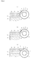
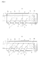
FIG. 3 is a drawing illustrating another example in which an exhaust connection pipe is disposed facing a direction in which the evaporation tube is not present within a zone in which the exhaust connection pipe is extended in the discharge direction of the exhaust gas.FIG. 3 (a) and (b) show the structure of a case where a discharge orifice of the exhaust connection pipe faces upwards.FIG. 3 (c) shows the structure of a case where the exhaust connection pipe is disposed in a horizontal orientation, and the center of the evaporation tube is shifted to a position lower than the position of the center of the exhaust connection pipe. -
FIG. 4 is a drawing illustrating another example in which exhaust connection pipes are arranged in a direction inclined toward the open end side of the evaporation tube, from a direction which is perpendicular to the lengthwise direction of the evaporation tube.FIG. 4 (a) illustrates a configuration in which the exhaust connection pipes are positioned on the side of the evaporation tube.FIG. 4 (b) illustrates a configuration in which the discharge orifices of the exhaust connection pipes are disposed in an upward position in the evaporation tube. -
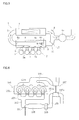
FIG. 5 is a drawing illustrating the configuration of another example, in which a switching valve is provided in order to perform a bypass so that exhaust gas is not fed to the denitration catalyst apparatus when denitration treatment is not necessary. -
FIG. 6 is a schematic drawing of a configuration of a conventional diesel engine of a ship. - The objects of the present invention, which are to conserve space in an exhaust gas emission purifying device, and also to prevent a decrease in catalytic performance due to the adsorption of intermediates such as ammonium sulfate and/or acidic ammonium sulfate if the fuel contains sulfur compounds, are achieved by means of an exhaust gas emission purifying device provided with an exhaust manifold which collects an exhaust gas discharged from exhaust connection pipes connected to exhaust ports of an engine, and which leads the exhaust gas into an exhaust passageway upstream of a turbine of a turbocharger; a denitration catalyst apparatus disposed in the exhaust passageway; an evaporation tube inside of the exhaust manifold, having one end connected to the exhaust passageway, and the other end opening into the exhaust manifold; as well as a nozzle which sprays at least one of an aqueous solution containing a reducing agent and a reducing agent precursor into the exhaust gas as it passes through the evaporation tube.
- In a case where the exhaust gas emission purifying device according to the present invention is configured with the exhaust connection pipes arranged facing a direction in which the evaporation tube is not present within a zone in which the exhaust connection pipe is extended in the discharge direction of the exhaust gas, it is advantageous for a high-temperature exhaust gas discharged from the exhaust connection pipe to circulate towards the periphery of the evaporation tube within the exhaust manifold without directly touching the evaporation tube, so that the entire outer periphery of the evaporation tube is efficiently heated, rather than heating the evaporation tube from the one side which faces the discharge orifice of the exhaust connection pipe.
- In a case where the exhaust gas emission purifying device according to the present invention is configured with the exhaust connection pipes arranged in a direction inclined toward the open side, from a direction perpendicular to the lengthwise direction of the evaporation tube, it is advantageous for a high-temperature exhaust gas discharged from the exhaust connection pipe to circulate towards the open end side on the outside of the evaporation tube, so that the exhaust gas within the exhaust manifold circulates while heating the entire length of the evaporation tube.
- Moreover, in a case where the exhaust gas emission purifying device according to the present invention is configured with the exhaust connection pipes arranged facing a direction in which the evaporation tube is not present within a zone in which the exhaust connection pipes are extended in the discharge direction of the exhaust gas, and with the exhaust connection pipes arranged in a direction inclined toward an open end side, from a direction perpendicular to the lengthwise direction of the evaporation tube, it is most advantageous for a high-temperature exhaust gas discharged from the exhaust connection pipe to circulate in a helical manner towards the open end side of the evaporation tube on the outside of the evaporation tube, so that the exhaust gas more favorably circulates within the exhaust manifold, while efficiently heating the entire periphery and the entire length of the evaporation tube.
- Various examples of the present invention are described in detail below, with reference being made to
FIGS. 1-5 . InFIG. 1 ,Reference Numeral 1 is an exhaust gas emission purifying device according to the present invention used in a 4-cylinder diesel engine for a ship. The exhaust gas emission purifyingdevice 1 is provided with anexhaust manifold 6 which collects an exhaust gas discharged fromexhaust connection pipes 3 which are respectively connected toexhaust ports 2a provided to cylinder heads of anengine 2, and which leads the exhaust gas into anexhaust passageway 5 upstream of aturbine 4a of aturbocharger 4, and adenitration catalyst apparatus 7 which is installed in theexhaust passageway 5. Reference Numeral 5a is an exhaust passageway downstream of theturbine turbocharger 4 which compresses air fed from anintake passageway 12a.Reference Numeral 10 is an intake manifold which distributes compressed air fed from anintake passageway 12 to anintake port 2b of a cylinder of theengine 2 via anintake connection pipe 11. - Inside of the
exhaust manifold 6 there is provided anevaporation tube 8 of which oneend 8a is connected to theexhaust passageway 5 and theother end 8b opens into theexhaust manifold 6. In addition, anozzle 9 is provided in a position in which it is able to spray anaqueous urea 9a in the vicinity of theopen end 8b of theevaporation tube 8 into the exhaust gas which passes through the interior of theevaporation tube 8 after being discharged from the discharge orifices of theexhaust connection pipes 3. - In the
denitration catalyst apparatus 7 there is provided an SCR catalyst which selectively reduces and removes NOx which causes environmental pollution such as acid rain and photochemical smog, when it is in exhaust gas discharged from theengine 2. The SCR catalyst may be any desired catalyst, such as a metal oxide-based catalyst such as alumina, zirconia, vanadia/titania, or the like, or a zeolite-based catalyst, and these catalysts may be used in combination. The SCR catalyst may be supported on a catalyst carrier having a honeycomb structure, and it may be inserted into a cylindrical cage. - If the SCR catalyst is used to break down NOx in exhaust gas into nitrogen and water, so as to detoxify it, a reducing agent such as ammonia must be supplied to the exhaust gas on the upstream side, but there is a risk involved in storing aqueous ammonia inside a ship. Therefore, in this example, urea is stored in the form of an aqueous solution to serve as a reducing agent precursor in a tank (not pictured) which is connected to the
nozzle 9. Then, during operation, theaqueous urea 9a is sprayed from thenozzle 9 into theevaporation tube 8, the heat of theevaporation tube 8 is used in hydrolyzing the urea, to form ammonia. - The
evaporation tube 8 is a tube-shaped member, of which the oneend 8a is connected to theexhaust passageway 5, and theother end 8b opens into theexhaust manifold 6. According to the exhaust gas emission purifying device of this example, thenozzle 9 is provided for spraying theaqueous urea 9a in the vicinity of theopen end 8b, and aflow regulator 8c is provided downstream of thenozzle 9 to regulate the flow of exhaust gas within theevaporation tube 8. The exhaust gas emission purifyingdevice 1 of this example is also provided with astatic mixer 8d downstream of theflow regulator 8c to thoroughly mix the exhaust gas and the ammonia gas formed when theaqueous ammonia 9a sprayed from thenozzle 9 is hydrolyzed inside theevaporation tube 8. - Therefore, according to the exhaust gas emission purifying
device 1 of the example illustrated inFIG. 1 , because theentire evaporation tube 8 equipped with theflow regulator 8c and thestatic mixer 8d is installed within theexhaust manifold 6, the device according to the present invention is designed to have a more compact size than the device of the prior art in which the exhaust manifold and the evaporation tube were both disposed in theexhaust passageway 5 upstream of theturbine 4a. - It should be noted that generally, in the case of an
engine 2 provided with aturbocharger 4, control delays can result from transient responses due to intake delays if theturbocharger 4 fails to respond to an increase in output demand from theengine 2 during a transient state such as acceleration. However, in the present invention, exhaust control is readily achieved, because the route of the exhaust gas to theturbocharger 4 can be made shorter than in the prior art device, in which the exhaust manifold and the evaporation tube were both disposed in theexhaust passageway 5 upstream of theturbine 4a. - Moreover, in the example illustrated in
FIG. 1 , theevaporation tube 8 is installed within theexhaust manifold 6 in such a manner that the lengthwise direction of theevaporation tube 8 is parallel to the direction in which the discharge orifices of theexhaust connection pipes 3 are serially arranged so as to face each of the respective discharge orifices of the exhaust connection pipes connected to theexhaust ports 2a of each of the cylinders of theengine 2. It is therefore possible to inhibit the formation of intermediates such as ammonium sulfate and/or acidic ammonium sulfate which cause a decrease in performance of thedenitration catalyst apparatus 7, and also to favorably support the NOx purifying performance of the SCR catalyst, even if the fuel contains a large quantity of sulfur compounds, because the wall surface of theevaporation tube 8 is heated high-temperature exhaust gas immediately after being discharged from theexhaust connection pipes 3. - Following is a description of the positional relationship between the
evaporation tubes 8 and the discharge orifices of theexhaust connection pipes 3 which open into theexhaust manifold 6, as well as the direction in which theexhaust connection pipes 3 are oriented.FIG. 2 is a drawing showing a vertical sectional view of theexhaust manifold 6 with theevaporation tube 8 included therein, as well as the vicinity of a cylinder head of anengine 2 appearing inFIG. 1 .Reference Numeral 2d is a cylinder head provided with theexhaust port 2a and theintake port 2b.Reference Numeral 2c is a cylinder block provided with a cylinder liner.Reference Numeral 2e is a piston connected to acrank 2f. Anarrow 11b indicates the direction in which fuel is supplied from afuel spray nozzle 11a by directly spraying it into the cylinders, and anarrow 11c indicates the direction in which compressed air is introduced by means of thecompressor 4b of theturbocharger 4. - In the example shown in
FIG. 2 , theexhaust connection pipe 3 is installed facing the center of theevaporation tube 8, with the center of theexhaust connection pipe 3 and the center of theevaporation tube 8 being positioned at the same height. In this case, theevaporation tube 8 is present within a zone in which theexhaust connection pipe 3 is extended in the discharge direction of the exhaust gas (within the zone enclosed by the dotted line indicated by A in the drawing). - Therefore, in a configuration of the type illustrated in
FIG. 2 , exhaust gas discharged from the discharge orifice of theexhaust connection pipe 3 makes direct contact with theevaporation tube 8 as shown by an arrow B, after which it separates vertically and proceeds to the back side of theevaporation tube 8. - By contrast, in the examples illustrated in
FIGS. 3 (a) and 3 (b) , thedischarge orifice 3a of theexhaust connection pipe 3 is disposed facing upwards. In this case, theevaporation tube 8 is not present within a zone in which theexhaust connection pipe 3 is extended in the discharge direction of the exhaust gas (within the zone enclosed by the dotted line indicated by A in the drawing). - In the example illustrated in
FIG. 3 (c) , theexhaust connection pipe 3 is disposed in a horizontal orientation, and the center of theevaporation tube 8 is shifted to a position lower than the position of the center of theexhaust connection pipe 3. In this case as well, theevaporation tube 8 is not present within a zone in which theexhaust connection pipe 3 is extended in the discharge direction of the exhaust gas (within the zone enclosed by the dotted line indicated by A in the drawing). - Therefore, in a configuration of the type illustrated in
FIG. 3 , high-temperature exhaust gas discharged from thedischarge orifice 3a of theexhaust connection pipe 3 does not make direct contact with theevaporation tube 8, and flows in around theevaporation tube 8 as shown by the arrow B, so it does not heat theevaporation tube 8 only from the surface of one side which faces thedischarge orifice 3a of theexhaust connection pipe 3, but rather, it is able to efficiently heat from the entire outer periphery of theevaporation tube 8. - It should be noted that in the example shown in
FIG. 3 (a) , the open end of thedischarge orifice 3a is formed facing a direction normal to the lengthwise direction of theexhaust connection pipe 3, but in the examples shown inFIGS. 3 (b) and 3 (c) , the open end of thedischarge orifice 3a is formed facing a direction diagonal to the lengthwise direction of theexhaust connection pipe 3, so that the front end of theexhaust connection pipe 3 which protrudes into theexhaust manifold 6 does not inhibit the stream of exhaust gas from flowing around theevaporation tube 8. In addition, theexhaust connection pipe 3 is disposed so that the forward end of the diagonally cut open end is positioned on the inner circumference side of theexhaust manifold 6. In the example shown inFIG. 3 , the open end of thedischarge orifice 3a is cut at 45°, for example. -
FIG. 4 is a drawing illustrating another example in which theexhaust connection pipes 3 are respectively arranged in a direction inclined toward theopen end 8b of theevaporation tube 8, from a direction perpendicular to the lengthwise direction of the evaporation tube 8 (the direction indicated by the line C).FIG. 4 is a sectional view only of theexhaust manifold 6 in a horizontal direction at a position in the center taken in a vertical direction. - In the example illustrated in
FIG. 4 (a) , theexhaust connection pipes 3 are positioned on a side of theevaporation tube 8, and disposed at an angle θ, which is 30°, for example, formed by the installation orientation of theexhaust connection pipes 3 with respect to a direction normal to the lengthwise direction of the evaporation tube 8 (the direction indicated by the line C). - Therefore, in a configuration of the type illustrated in
FIG. 4 (a) , high-temperature exhaust gas discharged from thedischarge orifices 3a of theexhaust connection pipes 3 flows toward theopen end 8b to the outside of theevaporation tube 8 within theexhaust manifold 6 in a direction indicated by an arrow D in the drawing, with the advantageous result that it heats the entire length of theevaporation tube 8. - In addition, if a configuration is employed such that the
exhaust connection pipes 3 are arranged in a direction inclined toward theopen end 8b of theevaporation tube 8, the resulting configuration combines the case in which the discharge orifices of theexhaust connection pipes 3 are disposed upwards towards theevaporation tube 8, and the case in which theexhaust connection pipes 3 are arranged so that they extend up to an upward position within theevaporation tube 8, so that theexhaust connection pipes 3 are arranged facing a direction in which theevaporation tube 8 is not present within a zone in which they are extended in the discharge direction of the exhaust gas, as illustrated inFIG. 4 (b) . - Therefore, in a configuration of the type illustrated in
FIG. 4 (b) , when an exhaust valve provided to theexhaust port 2a of theengine 2 is opened, the high-temperature gas discharged from theexhaust connection pipes 3 into theexhaust manifold 6 is directed towards theopen end 8b while tracing out a helical shape on the outer periphery of theevaporation tube 8, with the result that the entire circumference and the entire length of theevaporation tube 8 can be efficiently heated, and in addition, the flow of the exhaust gas within theexhaust manifold 6 is advantageous. - As described above, the exhaust gas emission purifying device according to the present invention is designed to conserve space to a greater extent than in prior art devices, because the exhaust gas emission purifying device according to the present invention is provided with a denitration catalyst apparatus disposed in the exhaust passageway upstream of the turbine of the turbocharger , and employs a configuration in which an evaporation tube having one end connected to an exhaust passageway inside of the exhaust manifold and the other end opens into the exhaust manifold, and a nozzle capable of spraying an aqueous solution of a reducing agent or the like into the exhaust gas as it passes through the evaporation tube. In addition, as a result of employing the above-described configuration, the exhaust gas emission purifying device according to the present invention is able to prevent a decrease in catalytic performance due to the adsorption of intermediates, even if the fuel contains a large quantity of sulfur compounds, because the evaporation tube does not decrease in temperature.
- The present invention is not limited to the above-described examples, and the embodiment may, of course, be advantageously modified within the scope of the technical ideas recited in the claims.
- For example, in the configuration of the example described above, denitration treatment was carried out by feeding exhaust gas into the ordinary
denitration catalyst apparatus 7 after being discharged from theexhaust connection pipes 3 into theexhaust manifold 6, but, as shown inFIG. 5 , a configuration may be employed in which there is provided abypass conduit 14 which discharges exhaust gas directly into theturbine 4a of the turbocharger without going through thedenitration catalyst apparatus 7 when denitration treatment with an SCR catalyst is not necessary, and in which there is provided a switchingvalve 13 for switching the routing of the exhaust gas. - Moreover, the above-described example disclosed a configuration in which the
aqueous urea 9a was sprayed as a reducing agent precursor from thenozzle 9 into the exhaust gas within theevaporation tube 8, but the components of the reducing agent precursor are not limited thereto. An aqueous solution mixture of high-concentration urea and low-concentration ammonia and/or aqueous ammonia may also be used. - According to the present invention, because the
evaporation tube 8 inside theexhaust manifold 6 is heated to an elevated temperature by a high-temperature exhaust gas immediately after being discharged from theexhaust connection pipes 3, an aqueous solution containing a reducing agent and/or a reducing agent precursor sprayed from thenozzle 9 is reliably vaporized or hydrolyzed while passing through theevaporation tube 8, regardless of what kind of components are used. In addition, a reducing agent in a vaporized state such as ammonia gas formed in theevaporation tube 8 can be delivered to thedenitration catalyst apparatus 7 together with the exhaust gas containing NOx, while maintaining a high-temperature state. - Moreover, the above-described example disclosed a case in which the
nozzle 9 was installed in the vicinity of theopen end 8b of theevaporation tube 8. However, the installation position of thenozzle 9 is not is not limited thereto, and it may be mounted in the center of theevaporation tube 8, for example. - Nonetheless, the
nozzle 9 is most advantageously installed in the vicinity of theopen end 8b of theevaporation tube 8, because that makes it possible to ensure a lengthy residence time for the sprayedaqueous urea 9a while it passes through the high-temperature evaporation tube 8. Also, if thenozzle 9 is installed in the vicinity of theopen end 8b of theevaporation tube 8, it is easy to ensure that there is space to install theflow regulator 8c andstatic mixer 8d. - The exhaust gas emission purifying device according to the present invention can be used in exhaust systems not only in diesel engines for ships, but also for automotive diesel engines.
-
- 1
- Exhaust gas emission purifying device
- 2
- Engine
- 2a
- Exhaust port
- 3
- Exhaust connection pipe
- 4
- Turbocharger
- 4a
- Turbine
- 5
- Exhaust passageway
- 6
- Exhaust manifold
- 7
- Denitration catalyst apparatus
- 8
- Evaporation tube
- 8a
- One end
- 8b
- Open end
- 9
- Nozzle
- 9a
- Aqueous urea
Claims (3)
- An exhaust gas emission purifying device comprising:an exhaust manifold which collects an exhaust gas discharged from exhaust connection pipes connected to exhaust ports of an engine, and which leads the exhaust gas into an exhaust passageway upstream of a turbine of a turbocharger;a denitration catalyst apparatus disposed in the exhaust passageway;an evaporation tube provided inside of the exhaust manifold, the evaporation tube having one end connected to the exhaust passageway and the other end opening into the exhaust manifold; anda nozzle that sprays an aqueous solution containing at least one of a reducing agent and a reducing agent precursor into the exhaust gas as it passes through the evaporation tube.
- The exhaust gas emission purifying device according to claim 1, wherein the exhaust connection pipes are arranged facing a direction in which the evaporation tube is not present within a zone in which the exhaust connection pipes are extended in the discharge direction of the exhaust gas.
- The exhaust gas emission purifying device according to claim 1 or claim 2, wherein the exhaust connection pipes are arranged in a direction inclined toward the open end side, from a direction perpendicular to the lengthwise direction of the evaporation tube.
Applications Claiming Priority (1)
| Application Number | Priority Date | Filing Date | Title |
|---|---|---|---|
| PCT/JP2011/070613 WO2013035199A1 (en) | 2011-09-09 | 2011-09-09 | Exhaust gas purifying apparatus |
Publications (3)
| Publication Number | Publication Date |
|---|---|
| EP2754865A1 true EP2754865A1 (en) | 2014-07-16 |
| EP2754865A4 EP2754865A4 (en) | 2015-05-06 |
| EP2754865B1 EP2754865B1 (en) | 2016-07-06 |
Family
ID=47831682
Family Applications (1)
| Application Number | Title | Priority Date | Filing Date |
|---|---|---|---|
| EP11871889.9A Not-in-force EP2754865B1 (en) | 2011-09-09 | 2011-09-09 | Exhaust gas purifying apparatus |
Country Status (4)
| Country | Link |
|---|---|
| EP (1) | EP2754865B1 (en) |
| KR (1) | KR101801629B1 (en) |
| CN (1) | CN103827455B (en) |
| WO (1) | WO2013035199A1 (en) |
Cited By (1)
| Publication number | Priority date | Publication date | Assignee | Title |
|---|---|---|---|---|
| DE102023103784A1 (en) * | 2023-02-16 | 2024-08-22 | Man Energy Solutions Se | Exhaust gas purification device of an internal combustion engine |
Families Citing this family (3)
| Publication number | Priority date | Publication date | Assignee | Title |
|---|---|---|---|---|
| JP2019152175A (en) * | 2018-03-06 | 2019-09-12 | 日立造船株式会社 | Exhaust emission control device |
| CN108714369A (en) * | 2018-07-25 | 2018-10-30 | 中国船舶重工集团柴油机有限公司 | A kind of exhaust emission combined removal device and method peculiar to vessel |
| JP2025151981A (en) * | 2024-03-28 | 2025-10-09 | マレリ株式会社 | Exhaust gas treatment device and mixing device |
Family Cites Families (13)
| Publication number | Priority date | Publication date | Assignee | Title |
|---|---|---|---|---|
| ZA803717B (en) * | 1979-06-29 | 1981-06-24 | Johnson Matthey Co Ltd | Exhaust gas purification |
| KR100229731B1 (en) * | 1990-07-27 | 1999-11-15 | 브룬너 하인리히 페터 울리히 | Large diesel engine |
| JP3140570B2 (en) * | 1992-07-27 | 2001-03-05 | 三菱重工業株式会社 | Denitration equipment for internal combustion engines |
| DE19745068C1 (en) * | 1997-10-11 | 1999-01-14 | Man B & W Diesel Gmbh | Two=stroke Diesel internal combustion engine |
| DK199801295A (en) * | 1998-10-12 | 2000-04-13 | Man B & W Diesel Gmbh | Combustion engine with a reactor for reducing NO x content in the exhaust gas and a method |
| JP4917208B2 (en) * | 2001-01-22 | 2012-04-18 | 川崎重工業株式会社 | Method and apparatus for supplying liquid reducing agent for denitration apparatus |
| JP2003260331A (en) | 2002-03-12 | 2003-09-16 | Mitsui & Co Ltd | Reducing agent composition for flue gas denitration |
| JP2005083220A (en) * | 2003-09-05 | 2005-03-31 | Nissan Diesel Motor Co Ltd | Exhaust emission control device |
| SE528119C2 (en) * | 2004-08-06 | 2006-09-05 | Scania Cv Ab | Arrangement for supplying a medium to an exhaust line of an internal combustion engine |
| DE102004042225B4 (en) * | 2004-09-01 | 2017-08-31 | MAN Truck & Bus Aktiengesellschaft | Apparatus and method for producing ammonia from solid urea pellets |
| JP2006283604A (en) * | 2005-03-31 | 2006-10-19 | Daihatsu Motor Co Ltd | Internal combustion engine |
| JP5582854B2 (en) * | 2010-04-13 | 2014-09-03 | 日立造船株式会社 | Exhaust gas purification device |
| EP2527611B1 (en) * | 2011-05-26 | 2016-11-09 | Wärtsilä Schweiz AG | Device and method for treating waste gas |
-
2011
- 2011-09-09 WO PCT/JP2011/070613 patent/WO2013035199A1/en not_active Ceased
- 2011-09-09 CN CN201180073115.8A patent/CN103827455B/en not_active Expired - Fee Related
- 2011-09-09 KR KR1020147004207A patent/KR101801629B1/en not_active Expired - Fee Related
- 2011-09-09 EP EP11871889.9A patent/EP2754865B1/en not_active Not-in-force
Cited By (1)
| Publication number | Priority date | Publication date | Assignee | Title |
|---|---|---|---|---|
| DE102023103784A1 (en) * | 2023-02-16 | 2024-08-22 | Man Energy Solutions Se | Exhaust gas purification device of an internal combustion engine |
Also Published As
| Publication number | Publication date |
|---|---|
| EP2754865A4 (en) | 2015-05-06 |
| EP2754865B1 (en) | 2016-07-06 |
| CN103827455A (en) | 2014-05-28 |
| WO2013035199A1 (en) | 2013-03-14 |
| KR101801629B1 (en) | 2017-11-27 |
| CN103827455B (en) | 2016-08-24 |
| KR20140071334A (en) | 2014-06-11 |
Similar Documents
| Publication | Publication Date | Title |
|---|---|---|
| EP2636861B1 (en) | Exhaust gas emission purification device | |
| KR102010198B1 (en) | Vessel Exhaust System | |
| JP5753485B2 (en) | Urea water spray structure | |
| US20080155973A1 (en) | Exhaust emission control device with additive injector | |
| CN108138622B (en) | Exhaust gas purification device for ships | |
| KR101619098B1 (en) | Exhaust gas purification device | |
| US20120124983A1 (en) | Exhaust system having reductant nozzle flow diverter | |
| CN203856551U (en) | Mixer module and exhaust cleaning module | |
| US20090064669A1 (en) | Additive-agent diffusion plate in exhaust passage, structure of additive-agent diffusion plate, and exhaust system including additive-agent diffusion plate | |
| JP5582854B2 (en) | Exhaust gas purification device | |
| EP2754865B1 (en) | Exhaust gas purifying apparatus | |
| JP2015086726A (en) | Exhaust gas purification system and ship equipped with the same | |
| JP7549970B2 (en) | Exhaust gas denitrification equipment | |
| JP2023167157A (en) | Exhaust emission control device | |
| KR20190062705A (en) | Reaction for selective catalytic reduction | |
| KR20200124650A (en) | Exhaust gas purification device | |
| KR20190062706A (en) | Selective catalytic reduction system |
Legal Events
| Date | Code | Title | Description |
|---|---|---|---|
| PUAI | Public reference made under article 153(3) epc to a published international application that has entered the european phase |
Free format text: ORIGINAL CODE: 0009012 |
|
| 17P | Request for examination filed |
Effective date: 20140311 |
|
| AK | Designated contracting states |
Kind code of ref document: A1 Designated state(s): AL AT BE BG CH CY CZ DE DK EE ES FI FR GB GR HR HU IE IS IT LI LT LU LV MC MK MT NL NO PL PT RO RS SE SI SK SM TR |
|
| DAX | Request for extension of the european patent (deleted) | ||
| RA4 | Supplementary search report drawn up and despatched (corrected) |
Effective date: 20150402 |
|
| RIC1 | Information provided on ipc code assigned before grant |
Ipc: F01N 3/24 20060101ALI20150327BHEP Ipc: F01N 3/28 20060101ALN20150327BHEP Ipc: B01D 53/94 20060101ALI20150327BHEP Ipc: F01N 3/08 20060101AFI20150327BHEP Ipc: F01N 13/10 20100101ALI20150327BHEP Ipc: F01N 3/20 20060101ALI20150327BHEP Ipc: F02B 37/00 20060101ALI20150327BHEP Ipc: F01N 13/00 20100101ALN20150327BHEP Ipc: F02B 67/00 20060101ALI20150327BHEP |
|
| RIC1 | Information provided on ipc code assigned before grant |
Ipc: F02B 67/00 20060101ALI20151125BHEP Ipc: F01N 13/00 20100101ALN20151125BHEP Ipc: F01N 3/28 20060101ALN20151125BHEP Ipc: F01N 3/24 20060101ALI20151125BHEP Ipc: F01N 3/20 20060101ALI20151125BHEP Ipc: B01D 53/94 20060101ALI20151125BHEP Ipc: F01N 3/08 20060101AFI20151125BHEP Ipc: F01N 13/10 20100101ALI20151125BHEP Ipc: F02B 37/00 20060101ALI20151125BHEP |
|
| GRAP | Despatch of communication of intention to grant a patent |
Free format text: ORIGINAL CODE: EPIDOSNIGR1 |
|
| INTG | Intention to grant announced |
Effective date: 20160122 |
|
| GRAS | Grant fee paid |
Free format text: ORIGINAL CODE: EPIDOSNIGR3 |
|
| GRAA | (expected) grant |
Free format text: ORIGINAL CODE: 0009210 |
|
| AK | Designated contracting states |
Kind code of ref document: B1 Designated state(s): AL AT BE BG CH CY CZ DE DK EE ES FI FR GB GR HR HU IE IS IT LI LT LU LV MC MK MT NL NO PL PT RO RS SE SI SK SM TR |
|
| REG | Reference to a national code |
Ref country code: GB Ref legal event code: FG4D |
|
| REG | Reference to a national code |
Ref country code: AT Ref legal event code: REF Ref document number: 810893 Country of ref document: AT Kind code of ref document: T Effective date: 20160715 Ref country code: CH Ref legal event code: EP |
|
| REG | Reference to a national code |
Ref country code: IE Ref legal event code: FG4D |
|
| REG | Reference to a national code |
Ref country code: DK Ref legal event code: T3 Effective date: 20160801 |
|
| REG | Reference to a national code |
Ref country code: DE Ref legal event code: R096 Ref document number: 602011028027 Country of ref document: DE |
|
| REG | Reference to a national code |
Ref country code: NL Ref legal event code: MP Effective date: 20160706 |
|
| REG | Reference to a national code |
Ref country code: LT Ref legal event code: MG4D |
|
| REG | Reference to a national code |
Ref country code: AT Ref legal event code: MK05 Ref document number: 810893 Country of ref document: AT Kind code of ref document: T Effective date: 20160706 |
|
| PG25 | Lapsed in a contracting state [announced via postgrant information from national office to epo] |
Ref country code: NO Free format text: LAPSE BECAUSE OF FAILURE TO SUBMIT A TRANSLATION OF THE DESCRIPTION OR TO PAY THE FEE WITHIN THE PRESCRIBED TIME-LIMIT Effective date: 20161006 Ref country code: NL Free format text: LAPSE BECAUSE OF FAILURE TO SUBMIT A TRANSLATION OF THE DESCRIPTION OR TO PAY THE FEE WITHIN THE PRESCRIBED TIME-LIMIT Effective date: 20160706 Ref country code: HR Free format text: LAPSE BECAUSE OF FAILURE TO SUBMIT A TRANSLATION OF THE DESCRIPTION OR TO PAY THE FEE WITHIN THE PRESCRIBED TIME-LIMIT Effective date: 20160706 Ref country code: IS Free format text: LAPSE BECAUSE OF FAILURE TO SUBMIT A TRANSLATION OF THE DESCRIPTION OR TO PAY THE FEE WITHIN THE PRESCRIBED TIME-LIMIT Effective date: 20161106 Ref country code: LT Free format text: LAPSE BECAUSE OF FAILURE TO SUBMIT A TRANSLATION OF THE DESCRIPTION OR TO PAY THE FEE WITHIN THE PRESCRIBED TIME-LIMIT Effective date: 20160706 Ref country code: RS Free format text: LAPSE BECAUSE OF FAILURE TO SUBMIT A TRANSLATION OF THE DESCRIPTION OR TO PAY THE FEE WITHIN THE PRESCRIBED TIME-LIMIT Effective date: 20160706 Ref country code: IT Free format text: LAPSE BECAUSE OF FAILURE TO SUBMIT A TRANSLATION OF THE DESCRIPTION OR TO PAY THE FEE WITHIN THE PRESCRIBED TIME-LIMIT Effective date: 20160706 |
|
| PG25 | Lapsed in a contracting state [announced via postgrant information from national office to epo] |
Ref country code: LV Free format text: LAPSE BECAUSE OF FAILURE TO SUBMIT A TRANSLATION OF THE DESCRIPTION OR TO PAY THE FEE WITHIN THE PRESCRIBED TIME-LIMIT Effective date: 20160706 Ref country code: SE Free format text: LAPSE BECAUSE OF FAILURE TO SUBMIT A TRANSLATION OF THE DESCRIPTION OR TO PAY THE FEE WITHIN THE PRESCRIBED TIME-LIMIT Effective date: 20160706 Ref country code: AT Free format text: LAPSE BECAUSE OF FAILURE TO SUBMIT A TRANSLATION OF THE DESCRIPTION OR TO PAY THE FEE WITHIN THE PRESCRIBED TIME-LIMIT Effective date: 20160706 Ref country code: ES Free format text: LAPSE BECAUSE OF FAILURE TO SUBMIT A TRANSLATION OF THE DESCRIPTION OR TO PAY THE FEE WITHIN THE PRESCRIBED TIME-LIMIT Effective date: 20160706 Ref country code: PT Free format text: LAPSE BECAUSE OF FAILURE TO SUBMIT A TRANSLATION OF THE DESCRIPTION OR TO PAY THE FEE WITHIN THE PRESCRIBED TIME-LIMIT Effective date: 20161107 Ref country code: GR Free format text: LAPSE BECAUSE OF FAILURE TO SUBMIT A TRANSLATION OF THE DESCRIPTION OR TO PAY THE FEE WITHIN THE PRESCRIBED TIME-LIMIT Effective date: 20161007 Ref country code: BE Free format text: LAPSE BECAUSE OF NON-PAYMENT OF DUE FEES Effective date: 20160706 Ref country code: PL Free format text: LAPSE BECAUSE OF FAILURE TO SUBMIT A TRANSLATION OF THE DESCRIPTION OR TO PAY THE FEE WITHIN THE PRESCRIBED TIME-LIMIT Effective date: 20160706 |
|
| REG | Reference to a national code |
Ref country code: DE Ref legal event code: R097 Ref document number: 602011028027 Country of ref document: DE |
|
| PG25 | Lapsed in a contracting state [announced via postgrant information from national office to epo] |
Ref country code: MC Free format text: LAPSE BECAUSE OF FAILURE TO SUBMIT A TRANSLATION OF THE DESCRIPTION OR TO PAY THE FEE WITHIN THE PRESCRIBED TIME-LIMIT Effective date: 20160706 Ref country code: RO Free format text: LAPSE BECAUSE OF FAILURE TO SUBMIT A TRANSLATION OF THE DESCRIPTION OR TO PAY THE FEE WITHIN THE PRESCRIBED TIME-LIMIT Effective date: 20160706 Ref country code: EE Free format text: LAPSE BECAUSE OF FAILURE TO SUBMIT A TRANSLATION OF THE DESCRIPTION OR TO PAY THE FEE WITHIN THE PRESCRIBED TIME-LIMIT Effective date: 20160706 |
|
| PLBE | No opposition filed within time limit |
Free format text: ORIGINAL CODE: 0009261 |
|
| STAA | Information on the status of an ep patent application or granted ep patent |
Free format text: STATUS: NO OPPOSITION FILED WITHIN TIME LIMIT |
|
| PG25 | Lapsed in a contracting state [announced via postgrant information from national office to epo] |
Ref country code: CZ Free format text: LAPSE BECAUSE OF FAILURE TO SUBMIT A TRANSLATION OF THE DESCRIPTION OR TO PAY THE FEE WITHIN THE PRESCRIBED TIME-LIMIT Effective date: 20160706 Ref country code: SK Free format text: LAPSE BECAUSE OF FAILURE TO SUBMIT A TRANSLATION OF THE DESCRIPTION OR TO PAY THE FEE WITHIN THE PRESCRIBED TIME-LIMIT Effective date: 20160706 Ref country code: SM Free format text: LAPSE BECAUSE OF FAILURE TO SUBMIT A TRANSLATION OF THE DESCRIPTION OR TO PAY THE FEE WITHIN THE PRESCRIBED TIME-LIMIT Effective date: 20160706 Ref country code: BG Free format text: LAPSE BECAUSE OF FAILURE TO SUBMIT A TRANSLATION OF THE DESCRIPTION OR TO PAY THE FEE WITHIN THE PRESCRIBED TIME-LIMIT Effective date: 20161006 |
|
| 26N | No opposition filed |
Effective date: 20170407 |
|
| GBPC | Gb: european patent ceased through non-payment of renewal fee |
Effective date: 20161006 |
|
| REG | Reference to a national code |
Ref country code: IE Ref legal event code: MM4A |
|
| REG | Reference to a national code |
Ref country code: FR Ref legal event code: ST Effective date: 20170531 |
|
| PG25 | Lapsed in a contracting state [announced via postgrant information from national office to epo] |
Ref country code: IE Free format text: LAPSE BECAUSE OF NON-PAYMENT OF DUE FEES Effective date: 20160909 Ref country code: FR Free format text: LAPSE BECAUSE OF NON-PAYMENT OF DUE FEES Effective date: 20160930 Ref country code: GB Free format text: LAPSE BECAUSE OF NON-PAYMENT OF DUE FEES Effective date: 20161006 |
|
| PG25 | Lapsed in a contracting state [announced via postgrant information from national office to epo] |
Ref country code: SI Free format text: LAPSE BECAUSE OF FAILURE TO SUBMIT A TRANSLATION OF THE DESCRIPTION OR TO PAY THE FEE WITHIN THE PRESCRIBED TIME-LIMIT Effective date: 20160706 Ref country code: LU Free format text: LAPSE BECAUSE OF NON-PAYMENT OF DUE FEES Effective date: 20160909 |
|
| PG25 | Lapsed in a contracting state [announced via postgrant information from national office to epo] |
Ref country code: HU Free format text: LAPSE BECAUSE OF FAILURE TO SUBMIT A TRANSLATION OF THE DESCRIPTION OR TO PAY THE FEE WITHIN THE PRESCRIBED TIME-LIMIT; INVALID AB INITIO Effective date: 20110909 |
|
| PG25 | Lapsed in a contracting state [announced via postgrant information from national office to epo] |
Ref country code: MT Free format text: LAPSE BECAUSE OF NON-PAYMENT OF DUE FEES Effective date: 20160930 Ref country code: MK Free format text: LAPSE BECAUSE OF FAILURE TO SUBMIT A TRANSLATION OF THE DESCRIPTION OR TO PAY THE FEE WITHIN THE PRESCRIBED TIME-LIMIT Effective date: 20160706 Ref country code: CY Free format text: LAPSE BECAUSE OF FAILURE TO SUBMIT A TRANSLATION OF THE DESCRIPTION OR TO PAY THE FEE WITHIN THE PRESCRIBED TIME-LIMIT Effective date: 20160706 |
|
| PG25 | Lapsed in a contracting state [announced via postgrant information from national office to epo] |
Ref country code: TR Free format text: LAPSE BECAUSE OF FAILURE TO SUBMIT A TRANSLATION OF THE DESCRIPTION OR TO PAY THE FEE WITHIN THE PRESCRIBED TIME-LIMIT Effective date: 20160706 Ref country code: AL Free format text: LAPSE BECAUSE OF FAILURE TO SUBMIT A TRANSLATION OF THE DESCRIPTION OR TO PAY THE FEE WITHIN THE PRESCRIBED TIME-LIMIT Effective date: 20160706 |
|
| PGFP | Annual fee paid to national office [announced via postgrant information from national office to epo] |
Ref country code: FI Payment date: 20210909 Year of fee payment: 11 Ref country code: CH Payment date: 20210916 Year of fee payment: 11 |
|
| PGFP | Annual fee paid to national office [announced via postgrant information from national office to epo] |
Ref country code: DE Payment date: 20210727 Year of fee payment: 11 Ref country code: DK Payment date: 20210909 Year of fee payment: 11 |
|
| REG | Reference to a national code |
Ref country code: DE Ref legal event code: R119 Ref document number: 602011028027 Country of ref document: DE |
|
| PG25 | Lapsed in a contracting state [announced via postgrant information from national office to epo] |
Ref country code: FI Free format text: LAPSE BECAUSE OF NON-PAYMENT OF DUE FEES Effective date: 20220909 |
|
| REG | Reference to a national code |
Ref country code: CH Ref legal event code: PL |
|
| REG | Reference to a national code |
Ref country code: DK Ref legal event code: EBP Effective date: 20220930 |
|
| PG25 | Lapsed in a contracting state [announced via postgrant information from national office to epo] |
Ref country code: LI Free format text: LAPSE BECAUSE OF NON-PAYMENT OF DUE FEES Effective date: 20220930 Ref country code: DE Free format text: LAPSE BECAUSE OF NON-PAYMENT OF DUE FEES Effective date: 20230401 Ref country code: CH Free format text: LAPSE BECAUSE OF NON-PAYMENT OF DUE FEES Effective date: 20220930 |
|
| PG25 | Lapsed in a contracting state [announced via postgrant information from national office to epo] |
Ref country code: DK Free format text: LAPSE BECAUSE OF NON-PAYMENT OF DUE FEES Effective date: 20220930 |