EP2754579A1 - Grille apparatus for vehicle - Google Patents
Grille apparatus for vehicle Download PDFInfo
- Publication number
- EP2754579A1 EP2754579A1 EP14150621.2A EP14150621A EP2754579A1 EP 2754579 A1 EP2754579 A1 EP 2754579A1 EP 14150621 A EP14150621 A EP 14150621A EP 2754579 A1 EP2754579 A1 EP 2754579A1
- Authority
- EP
- European Patent Office
- Prior art keywords
- grille
- cover
- covers
- vehicle
- opening portion
- Prior art date
- Legal status (The legal status is an assumption and is not a legal conclusion. Google has not performed a legal analysis and makes no representation as to the accuracy of the status listed.)
- Granted
Links
Images






Classifications
-
- B—PERFORMING OPERATIONS; TRANSPORTING
- B60—VEHICLES IN GENERAL
- B60K—ARRANGEMENT OR MOUNTING OF PROPULSION UNITS OR OF TRANSMISSIONS IN VEHICLES; ARRANGEMENT OR MOUNTING OF PLURAL DIVERSE PRIME-MOVERS IN VEHICLES; AUXILIARY DRIVES FOR VEHICLES; INSTRUMENTATION OR DASHBOARDS FOR VEHICLES; ARRANGEMENTS IN CONNECTION WITH COOLING, AIR INTAKE, GAS EXHAUST OR FUEL SUPPLY OF PROPULSION UNITS IN VEHICLES
- B60K11/00—Arrangement in connection with cooling of propulsion units
- B60K11/08—Air inlets for cooling; Shutters or blinds therefor
- B60K11/085—Air inlets for cooling; Shutters or blinds therefor with adjustable shutters or blinds
-
- B—PERFORMING OPERATIONS; TRANSPORTING
- B60—VEHICLES IN GENERAL
- B60K—ARRANGEMENT OR MOUNTING OF PROPULSION UNITS OR OF TRANSMISSIONS IN VEHICLES; ARRANGEMENT OR MOUNTING OF PLURAL DIVERSE PRIME-MOVERS IN VEHICLES; AUXILIARY DRIVES FOR VEHICLES; INSTRUMENTATION OR DASHBOARDS FOR VEHICLES; ARRANGEMENTS IN CONNECTION WITH COOLING, AIR INTAKE, GAS EXHAUST OR FUEL SUPPLY OF PROPULSION UNITS IN VEHICLES
- B60K11/00—Arrangement in connection with cooling of propulsion units
- B60K11/08—Air inlets for cooling; Shutters or blinds therefor
-
- Y—GENERAL TAGGING OF NEW TECHNOLOGICAL DEVELOPMENTS; GENERAL TAGGING OF CROSS-SECTIONAL TECHNOLOGIES SPANNING OVER SEVERAL SECTIONS OF THE IPC; TECHNICAL SUBJECTS COVERED BY FORMER USPC CROSS-REFERENCE ART COLLECTIONS [XRACs] AND DIGESTS
- Y02—TECHNOLOGIES OR APPLICATIONS FOR MITIGATION OR ADAPTATION AGAINST CLIMATE CHANGE
- Y02T—CLIMATE CHANGE MITIGATION TECHNOLOGIES RELATED TO TRANSPORTATION
- Y02T10/00—Road transport of goods or passengers
- Y02T10/80—Technologies aiming to reduce greenhouse gasses emissions common to all road transportation technologies
- Y02T10/88—Optimized components or subsystems, e.g. lighting, actively controlled glasses
Definitions
- This disclosure generally relates to a grille apparatus for a vehicle.
- Patent reference 1 A known grille apparatus for a vehicle configured with plural cover members (elongated plates for the grille apparatus) arranged at an opening portion of a front grille of a vehicle to change an opening amount of the front grille by rotating the cover members is disclosed in JPS58-139519U (hereinafter referred to as Patent reference 1).
- an aerodynamic performance (for example, Cd value, that is, coefficient of drag) of the vehicle is enhanced by limiting a flow rate of air flowing into an engine room by reducing an opening amount of a front grille (closed state).
- Cd value that is, coefficient of drag
- warm-up time is shortened by reducing the flow rate of air introduced into a radiator of the vehicle.
- the opening amount of the front grille is increased to raise the flow rate of air flowing into the engine room (open state) so that the engine temperature is controlled at an appropriate temperature.
- Patent reference 2 Another grille apparatus is disclosed in 2012-148705A (hereinafter referred to as Patent reference 2).
- the grille apparatus disclosed in Patent reference 2 is configured with a second cover member performing opening and closing operations between a closed position to close an opening portion of a front grille and an open position to open the opening portion of the front grille.
- the second cover member is arranged at the position where frontward of first cover members is covered and moves to a position where the frontward of the first cover members is exposed. Then, an opening amount of the front grille may be changed, or varied reliably regardless of shapes of the cover members.
- Patent reference 2 because a stroke of the second cover member for the opening and closing operations, that is, a moving distance of the second cover member, is increased, the grille apparatus disclosed in Patent reference 2 requires not only time to open and close the opening portion of the front grille but also a large space for arranging a housing portion for the second cover member and for arranging a movement mechanism that moves the second cover member. Thus, the mountability is decreased.
- a grille apparatus for a vehicle includes a first cover arranged at an opening portion of a front grille, a second cover arranged at the opening portion of the front grille, and a drive mechanism changing a relative position of the first cover and the second cover in response to a driving force of a drive source, in which the drive mechanism changes an opening amount of the front grille by performing an opening operation moving the second cover to a rear of the first cover, and by performing a closing operation returning the second cover to a fully-closed position, the fully-closed position before moving the second cover to the rear of the first cover while maintaining the first cover and the second cover within the opening portion of the front grille.
- opening areas are formed between the first covers adjacent to one another because the second covers move to the rear of the respective first covers regardless of a shape of cover members. Accordingly, the opening amount of the front grille may be changed, or varied reliably. Further, by positioning the first covers and the second covers within the opening portion of the front grille, a stroke of the opening and closing operations of the grille apparatus for a vehicle, that is, a moving distance of the second covers may be shortened. As a result, an operation time is reduced and a mountability of the device is enhanced by a size decrease of the device.
- the opening operation and the closing operation are performed by a sliding movement of the second cover.
- the relative position of the cover members may be changed, or varied reliably.
- reliable opening and closing operations of the grille apparatus for a vehicle may be secured.
- the sliding movement includes a movement of the second cover to the rear in a vehicle front-rear direction from the fully-closed position when the opening operation is performed, and a movement of the second cover to the front in the vehicle front-rear direction to return to the fully-closed position when the closing operation is performed.
- an interference between the cover members may be prevented.
- the reliable opening and closing operations of the grille apparatus for a vehicle may be secured.
- the drive mechanism includes a supporting member supporting the second cover, a guide protrusion provided at the supporting member, a bracket including a guide groove engaging with the guide protrusion, and a driving force transmission mechanism moving the second cover integrally with the supporting member by transmitting the driving force of the drive source to the supporting member.
- the second covers reliably operate the sliding movement with a simple configuration.
- the reliable opening and closing operations of the grille apparatus for a vehicle may be secured.
- the drive mechanism is arranged at an end portion of the opening portion of the front grille in the direction intersecting the sliding movement direction of the second cover within the opening portion of the front grille.
- the supporting member including the guide protrusion), the bracket and the driving force transmission mechanism which configure the drive mechanism may be collectively arranged at a position where the drive mechanism may not prevent air from flowing in via the opening portion of the front grille.
- the mountability of the device may be enhanced without losing the function as the grille apparatus that takes air at a front of the vehicle into an inner space of the vehicle body.
- the driving force transmission mechanism includes a moving body connected to the supporting member and a conversion mechanism converting the driving force of the drive source into a reciprocating movement of the moving body.
- the moving body may operate the reliable reciprocating movement by applying a simple configuration including a known rack and pinion mechanism (a pinion gear and a rack belt).
- a simple configuration including a known rack and pinion mechanism (a pinion gear and a rack belt).
- the bracket includes a storage chamber slidably accommodating the moving body.
- the mountability of the device is enhanced by the size decrease of the device.
- the moving body includes an engaging recessed portion engaging with the guide protrusion to be connected to the supporting member.
- the moving body and the bracket may be collectively arranged.
- the mountability of the device is enhanced.
- the plural first covers and the plural second covers are arranged alternately in line when the second cover is in the fully-closed position.
- the stroke of the opening and closing operations of the grille apparatus for a vehicle may be shortened.
- the mountability of the device is enhanced by the size decrease of the device.
- aerodynamic characteristics may be further improved by arranging the cover members in line.
- the drive mechanism includes the first drive mechanism and the second drive mechanism that are arranged at positions to sandwich the drive source.
- two drive mechanisms may be performed by a single motor, the drive source, with a simple configuration.
- the first cover and the second cover are arranged alternately in line in a width direction of the opening portion of the front grille when the second cover is in the fully-closed position.
- an influence of the gravity almost does not have to be considered for moving the second covers.
- the reliable opening and closing operations may be secured with a further simple configuration.
- the aerodynamic characteristics may be further improved by arranging the cover members in line.
- the opening amount of the front grille may be changed, or varied further reliably while the mountability of the device is enhanced.
- a front grille 2 configuring a front design face S of a vehicle 1 includes an opening portion of the front grille 2 (a grille opening portion 4) which connects an outer space at a front of the vehicle 1 and an inner space of a vehicle body 3.
- a radiator 7 is accommodated in an engine room 5 which is arranged at the vehicle body 3 to cool an engine 6.
- the grille opening portion 4 of the embodiment is arranged at a center in a width direction of the front grille 2 (left-right direction in Figs. 2 and 3 ) and, for details, the grille opening portion 4 of the embodiment is arranged above a bumper 8 and a bumper reinforcement 9.
- the radiator 7 is arranged at a position frontward of the engine 6 in the engine room 5, the position where the radiator 7 receives air flowing via the grille opening portion 4 into the engine room 5.
- plural cover members C are arranged inside the grille opening portion 4.
- the grille opening portion 4 takes air flowing via clearances formed between each of the cover members C into the engine room 5.
- a center cover 12 is arranged inside the grille opening portion 4 to close a center in a width direction of the grille opening portion 4.
- a hole portion 11 is formed at the center cover 12 of the embodiment for mounting an automobile emblem plate of the vehicle 1.
- Plural first covers 21 and plural second covers 22 are arranged at opposing sides in the width direction of the center cover 12.
- Figs. 4 and 5 illustrate a state where the first covers 21 and the second covers 22 arranged at one of the opposing sides in the width direction of the center cover 12 (at right in Figs. 4 and 5 ) are removed.
- a drive mechanism 30 is positioned at a rear of the cover members C to change a relative position of the first covers 21 and the second covers 22 in response to a driving force of a motor 25 (serving as a drive source) as a drive source.
- the first covers 21 and the second covers 22 are extended in an up-down direction of the vehicle 1 (up-down direction in Fig. 2 ) being formed in a three dimensional-shape such that each of middle portions in the up-down direction of the first covers 21 and the second covers 22 protrudes toward the center in the width direction of the grille opening portion 4 and forward of the vehicle 1.
- the first covers 21 are arranged inside the grille opening portion 4 to be spaced from one another in the width direction of the grille opening portion 4.
- the second covers 22 are arranged inside the grille opening portion 4 to be spaced from one another in the width direction of the grille opening portion 4.
- the drive mechanism 30 of the embodiment changes the relative position of the first covers 21 and the second covers 22 between a fully-closed state of the grille apparatus 20 for a vehicle (fully-closed position P1) and a fully-open state of the grille apparatus 20 for a vehicle (fully-open position P3).
- the first covers 21 and the second covers 22 are arranged alternately in line in the width direction of the grille opening portion 4 so that the grille apparatus 20 for a vehicle is in the fully-closed state (fully-closed position P1).
- the second covers 22 move to a rear of the respective first covers 21 so that the grille apparatus 20 for a vehicle is in the fully-open state (fully-open position P3).
- the size of the clearance formed between the cover members C is changed, or varied as the relative position of first covers 21 and the second covers 22 is changed, or varied in the grille opening portion 4.
- the grille opening portion 4 is closed when the first covers 21 and the second covers 22 are arranged alternately in line. Opening areas ⁇ are formed between the first covers 21 adjacent to one another in the width direction of the grille opening portion 4 as the second covers 22 move to the rear of the corresponding first covers 21.
- the grille apparatus 20 for a vehicle is configured such that the opening amount of the front grille 2 may be changed, or varied.
- the center cover 12 and the first covers 21 are fixed to opposite open ends in the up-down direction of the grille opening portion 4.
- the drive mechanism 30 may move the second covers 22 to the rear of the respective first covers 21 which are adjacent to the second covers 22 in the fully-closed state of the grille apparatus 20 for a vehicle by sliding the second covers 22 in a vehicle front-rear direction and in the width direction of the grille opening portion 4.
- the drive mechanism 30 of the embodiment includes a supporting member 31, a guide protrusion 32, and a bracket 34.
- the supporting member 31 supports the second covers 22.
- the guide protrusion 32 is mounted to the supporting member 31.
- the bracket 34 includes a guide groove 33 that engages with the respective guide protrusion 32.
- the drive mechanism 30 includes a driving force transmission mechanism 35 which transmits the driving force of the motor 25 to the supporting member 31 to move the second covers 22 integrally with the supporting member 31.
- a movement trajectory of the second cover 22 (and the supporting member 31) is determined by a groove shape of the guide groove 33.
- the motor 25 as a drive source is arranged at a substantially center in the width direction of the grille opening portion 4 and a rearward of the center cover 12.
- the motor 25 is mounted with a reduction gear 36 that reduces a rotational speed of the motor 25.
- the grille apparatus 20 for a vehicle of the embodiment includes the left-right pair of the drive mechanisms 30 (a first drive mechanism 30L and a second drive mechanism 30R) arranged to sandwich the motor 25 in the width direction of the grille opening portion 4.
- the single motor 25 drives the second covers 22 arranged at the opposing sides of the center cover 12 in the width direction of the grille opening portion 4.
- the drive mechanism 30 of the embodiment includes the upper-lower pair of the supporting members 31 (a first supporting member 31A, a second supporting member 31 B).
- the lower-arranged first supporting member 31A supports a lower end portion 22a of each of the second covers 22 while the upper-arranged second supporting member 31B supports an upper end portion 22b of each of the second covers 22.
- Each of the supporting members 31 includes a base portion 31 a and plural (for example, three) branch portions 31 b.
- the base portion 31 a extends in the width direction of the grille opening portion 4 (left-right direction in Fig. 7 ).
- the branch portions 31 b extend frontward in the vehicle front-rear direction from the base portion 31 a so that front ends in the vehicle front-rear direction of the branch portions 31b are fixed to the respective second covers 22.
- Each of the supporting members 31 (the first supporting member 31A, the second supporting member 31 B) is arranged at a lower end portion 4a (serving as an end portion) and an upper end portion 4b (serving as an end portion) of the grille opening portion 4, respectively.
- the lower end portion 4a and the upper end portion 4b are arranged at opposing ends of the grille opening portion 4, the opposing ends orthogonal to the sliding direction of the second covers 22, that is, orthogonal to the width direction of the grille opening portion 4 and orthogonal to the vehicle front-rear direction.
- the supporting members 31 (the first supporting member 31A, the second supporting member 31 B) are connected one another by a shaft-shaped connection member 37 and are bridged between the base portions 31 a of the supporting members 31 (the first supporting member 31A, the second supporting member 31 B).
- the first supporting member 31A supporting the lower end portions 22a of the second covers 22 includes shaft-shaped, plural (for example, two) first guide protrusions 32A protruding downward.
- a first bracket 34A including plural first guide grooves 33A (for example, two, for each of the first supporting member 31A) engaging with the first guide protrusions 32A is provided.
- the first bracket 34A is formed such that a first member 34a and a second member 34b both formed in a substantially elongated flat plate are overlapped one another.
- the first guide groove 33A includes oblong hole-shaped first and second through holes 38a and 38b arranged at the first member 34a and the second member 34b, respectively.
- the first and second through holes 38a and 38b penetrate in a thickness direction of the first member 34a and the second member 34b, respectively.
- a second supporting member 31B supporting the upper end portions 22b of the second covers 22 include shaft-shaped second guide protrusions 32B protruding upward.
- a second bracket 34B formed in an elongated flat plate-shape and including second guide grooves 33B engaging with the second guide protrusions 32B is provided (upper in Fig. 8 ).
- the second guide grooves 33B include oblong hole-shaped third through holes 38c penetrating in the thickness direction of the second bracket 34B.
- the drive mechanisms 30 (the first drive mechanism 30L and the second drive mechanism 30R) driving the second covers 22 which are arranged at the opposing sides in the width direction of the center cover 12 are formed integrally with the first bracket 34A (configured by the first member 34a and the second member 34b) and the second bracket 34B that are symmetrically connected.
- the lower-arranged first bracket 34A and the upper-arranged second bracket 34B are positioned at the lower end portion 4a and the upper end portion 4b of the grille opening portion 4, respectively, in a substantially horizontal manner along with the width direction of the grille opening portion 4 so that the first bracket 34A and the second bracket 34B are in parallel with one another.
- the driving force transmission mechanism 35 of the embodiment includes a moving body 40 and a conversion mechanism 41.
- the moving body 40 is connected to the first supporting member 31A.
- the conversion mechanism 41 converts a rotation of the motor 25 as a drive source into a reciprocating movement of the moving body 40.
- the second covers 22 supported by the first supporting member 31A perform opening and closing operations as the first supporting member 31A moves in response to the reciprocating movement of the moving body 40.
- the moving body 40 of the embodiment is formed in a substantially rectangular flat plate (formed in a slightly parallelogram shape).
- the moving body 40 includes plural engaging recessed portions 42 engaging with the first guide protrusions 32A of the first supporting member 31A.
- the engaging recessed portions 42 include oblong hole-shaped fourth through holes 38d penetrating in the thickness direction of the moving body 40.
- the engaging recessed portion 42 and the first guide protrusion 32A are engaged with one another so that the moving body 40 of the embodiment is connected to the first supporting member 31A in a state where the first supporting member 31A can move in response to the reciprocating movement of the moving body 40.
- the conversion mechanism 41 of the embodiment is configured with a pinion gear 44 rotated by a motor drive and rack belts 45 meshing with the pinion gear 44. That is, the rack belt 45 is a rack gear made of a flexible material, for example, resin. The rack belt 45 meshes with the pinion gear 44 to be configured as a known rack and pinion mechanism. As illustrated in Fig. 11 , an end in a longitudinal direction of the rack belt 45 is fixed to a longitudinal side 40x of the moving body 40. Accordingly, the conversion mechanism 41 of the embodiment allows the moving body 40 to perform the reciprocating movement in a longitudinal direction of the rack belt 45.
- the lower-arranged first bracket 34A includes a storage chamber 50 accommodating the moving body 40 while allowing the reciprocating movement of the moving body 40 along with the longitudinal direction of the first bracket 34A, that is, the width direction of the grille opening portion 4 (left-right direction in Fig. 6 ).
- the first member 34a and the second member 34b configuring the first bracket 34A include slidable recessed portions 51 a, 51 b, respectively, where the moving body 40 and the rack belt 45 are arranged. That is, according to the embodiment, as illustrated in Figs. 7 and 12 , the first member 34a and the second member 34b are assembled so that the first member 34a and the second member 34b sandwich the moving body 40 (and the end in the longitudinal direction of the rack belt 45).
- the storage chamber 50 accommodating the moving body 40 is formed with the slidable recessed portions 51a, 51b which close opening portions of the slidable recessed portions 51a, 51 b one another.
- the storage chamber 50 includes opposite sidewalls 50a, 50b.
- Each of the opposite sidewalls 50a, 50b extending in the longitudinal direction of the first bracket 34A includes a guiding surface s1 on which the moving body 40 slides inside the storage chamber 50.
- the guide surface s1 configured with each of the sidewalls 50a, 50b is formed such that the moving body 40 moves obliquely rearward in the vehicle front-rear direction when the moving body 40 moves from the center to an outer portion in the width direction of the grille opening portion 4.
- the first supporting member 31A is assembled such that the first guide protrusion 32A protrudes downward of the first supporting member 31A to penetrate the first through hole 38a, the second through hole 38b and the fourth through hole 38d.
- the first through hole 38a and the second through hole 38b are arranged at the first member 34a and the second member 34b, respectively, of the first guide groove 33A of the first bracket 34A.
- the fourth through hole 38d is arranged at the engaging recessed portion 42 of the moving body 40.
- the second covers 22 supported by the first supporting member 31A move in response to the reciprocating movement of the moving body 40 inside the storage chamber 50 by connecting the moving body 40 to the first supporting member 31A.
- each of the first and second through holes 38a, 38b arranged at the first guide groove 33A of the first bracket 34A is formed in a curved groove-shape and extended in the vehicle front-rear direction at the center in the width direction of the grille opening portion 4 while extending in the width direction of the grille opening portion 4 at an outer portion in the width direction of the grille opening portion 4.
- the second guide groove 33B of the upper-arranged second bracket 34B is formed in the same curved groove-shape as the first guide groove 33A of the first bracket 34A.
- the grille apparatus 20 for a vehicle can perform the opening operation forming the opening areas ⁇ by moving the second covers 22 to the rear of the respective first covers 21 (fully-open position P3) without interfering the first covers 21 that are adjacent to the second covers 22 in the width direction of the grille opening portion 4.
- the grille apparatus 20 for a vehicle can perform the closing operation by returning the relative position of the first covers 21 and the second covers 22 to the fully-closed position P1, the relative position before the second covers 22 move to the rear of the respective first covers 21.
- the engaging recessed portion 42 (the fourth through hole 38d) of the moving body 40 is formed such that the first guide protrusion 32A moves obliquely forward in the vehicle front-rear direction from the center to outward in the width direction of the grille opening portion 4 (up-down direction in Fig. 11 ). That is, a wall surface of the engaging recessed portion 42 presses the first guide protrusion 32A in response to the reciprocating movement of the moving body 40.
- the first supporting member 31A and the second covers 22 move in response to the driving force transmitted via the first guide protrusion 32A.
- the driving force is transmitted efficiently by applying the oblong hole-shaped engaging recessed portion 42.
- the first guide protrusion 32A includes rollers 57 and 58 provided at positions where the first guide groove 33A and the engaging recessed portion 42 are engaged with the first guide protrusion 32A. Because the rollers 57, 58 are slidably in contact with, and rotate on the wall surfaces of the first guide groove 33A and engaged recessed portion 42, a smooth movement of the second covers 22 is ensured.
- the grille apparatus 20 for a vehicle of the embodiment performs the opening operation by moving the moving body 40 from the center to the outer portion in the width direction of the grille opening portion 4 (from left to right in Figs. 13 to 15 ) in response to the driving force of the motor 25.
- the grille apparatus 20 for a vehicle performs the closing operation by moving the moving body 40 from the outer portion to the center in the width direction of the grille opening portion 4 (from right to left in Figs. 13 to 15 ).
- the moving body 40 arranged in the storage chamber 50 of the first bracket 34A is positioned close to an end wall 50c arranged at the center in the width direction of the grille opening portion 4 (left in Fig. 13 ).
- the guide protrusion 32 (32A) engaging with the guide groove 33 (33A) of the bracket 34 (34A) is positioned close to a center end of the guide groove 33 (33A) (left in Fig. 13 ) in the width direction of the grille opening portion 4.
- the guide protrusion 32 engaging with the guide groove 33 moves from close to the center end to the outer end of the guide groove 33 in the width direction of the grille opening portion 4 in response to a sliding movement of the moving body 40 from close to the center end to the outer portion in the width direction of the grille opening portion 4.
- the second covers 22 supported by the first supporting member 31A move to the rear of the respective first covers 21, which are adjacent to the second covers 22 in the width direction of the grille opening portion 4.
- the guide protrusion 32 engaging with the guide groove 33 moves from close to the outer end to the center end of the guide groove 33 in the width direction of the grille opening portion 4 in response to the sliding movement of the moving body 40 from close to the outer end to close to the center end in the width direction of the grille opening portion 4. Accordingly, the second covers 22 return to the position, the fully-closed position P1 where the opening areas ⁇ formed by the second covers 22 moving to the rear of the respective first covers 21 are closed.
- the second covers 22 move mainly in the vehicle front-rear direction of the grille opening portion 4 to accord with a curved groove-shape of the guide groove 33 at a space close to the fully-closed position P1 where the guide protrusion 32 within the guide groove 33 moves between close to the center end and close to a middle portion of the guide groove 33 in the width direction of the grille opening portion 4.
- the second covers 22 move mainly in the width direction of the grille opening portion 4 to accord with the curved groove-shape of the guide groove 33 at a space close to the fully-open position P3 where the guide protrusion 32 within the guide groove 33 moves between close to the middle portion and close to the outer end of the guide groove 33 in the width direction of the grille opening portion 4.
- the sliding movement of the second covers 22 by the drive mechanism 30 includes a movement of the second covers 22 to the rear in the vehicle front-rear direction from the fully-closed position P1 when the opening operation is performed.
- the sliding movement of the second covers 22 by the drive mechanism 30 further includes a movement of the second covers 22 to a front in the vehicle front-rear direction to return to the fully-closed position P1 when the closing operation is performed (see Figs. 13 and 14 ).
- the second covers 22 slide in the width direction of the grille opening portion 4 at the rear position in the vehicle front-rear direction without interfering the first covers 21 which are adjacent to the second covers 22. Accordingly, smooth opening and closing operations of the grille apparatus 20 for a vehicle are secured.
- An Engaging position of the engaging recessed portion 42 of the moving body 40 and the guide protrusion 32 moves from close to the outer end to close to the center ends of the engaging recessed portions 42 of the in the width direction of the grille opening portion 4 when the opening operation is performed in response to the sliding movement of the moving body 40.
- the engaging position of the engaging recessed portion 42 of the moving body 40 and the guide protrusion 32 moves from close to the center end to close to the outer end of the engaging recessed portion 42 in the width direction of the grille opening portion 4 when the closing operation is performed in response to the sliding movement of the moving body 40.
- the wall surface of the engaging recessed portion 42 presses the guide protrusion 32 reliably.
- air flowing via the grille opening portion 4 flows into the engine room 5 which is formed in the vehicle body 3.
- air flows into any inner space, for example, a housing of a heat exchanger such as the radiator 7 other than the engine room 5 as long as the grille apparatus 20 for a vehicle includes a clearance where air flows via the grille opening portion 4.
- the grille shutter apparatus 10 of the embodiment is applied to a vehicle in which an engine is arranged at a rear or a center of a vehicle body, or to a vehicle such as an electric vehicle in which an engine is not mounted on an frontward of a vehicle compartment of an inner body of a vehicle.
- each of the cover members C is arranged at the grille opening portion 4 formed at an upper the bumper 8.
- the grille opening portion 4 can be formed at a lower of the bumper 8.
- the first covers 21 and the second covers 22 are formed in the three-dimensional shape such that each of the middle portions in the vehicle up-down direction of the first covers 21 and the second covers 22 protrudes toward the center in the width direction of the grille opening portion 4 and forward of the vehicle 1.
- the shapes of the cover members C including the center cover 12 are changed, or varied arbitrarily.
- the number of the cover members C can be changed, or varied arbitrarily.
- the same as the center cover 12, the plural cover members C in which the second covers 22 do not move to the rear of the respective first covers 21 may be provided.
- the cover members C, such as the center cover 12, that are not related to the opening and closing operation of the grille opening portion 4 may not be provided. That is, the grille apparatus 20 for a vehicle may include at least one of the first covers 21 maintained within the grille opening portion 4 and at least one of the second covers 22 moving to the rear of the respective first covers 21 within the grille opening portion 4.
- the status can be defined as the fully-closed state of the grille apparatus 20 for a vehicle.
- the first covers 21 and the second covers 22 are unnecessarily arranged in a straight line.
- the fully-closed state of the grille apparatus 20 for a vehicle does not necessarily have to be a completely closed state in which no clearance for air flowing in is provided between the cover members C.
- the first covers 21 and the second covers 22 may be arranged in parallel with one another in the up-down direction of the grille opening portion 4.
- the drive mechanism 30 is favorably arranged at a side end of the grille opening portion 4.
- the second covers 22 do not necessarily have to move to the rear of the respective first covers 21 completely as long as the grille opening portion 4 includes new opening areas ⁇ that directly take air into the inner space of the vehicle body 3 without being interrupted by the cover members C at a front of the vehicle body 3.
- the grille apparatus 20 for a vehicle performs opening and closing operations by sliding the second covers 22.
- the second covers 22 may, for example, rotate or incline to move to the rear of the respective first covers 21.
- the sliding movement of the second covers 22 may also include rotation and inclination.
- the first covers 21 are fixed to the opposite open ends in the up-down direction of the grille opening portion 4.
- the first covers 21 may be moved including rotation and inclination as long as the first covers 21 and the second covers 22 are accommodated in the grille opening portion 4 when the grille apparatus 20 for a vehicle performs the opening operation.
- the motor 25 is applied as a drive source.
- other drive sources including a solenoid may be applied as a drive source.
- the motor 25 as the drive source is arranged at a substantially center in the width direction of the grille opening portion 4.
- the grille apparatus 20 for a vehicle includes the left-right pair of the drive mechanisms 30 (the first drive mechanism 30L and the second drive mechanism 30R) arranged to sandwich the motor 25 in the width direction of the grille opening portion 4.
- a drive source may be positioned arbitrarily.
- the motor 25 may be arranged at a side end in the width direction of the grille opening portion 4. In this case, all the second covers 22 may be driven by the single drive mechanism 30.
- the motor 25 may be arranged at a position where the drive mechanisms 30 (the first drive mechanism 30L and the second drive mechanism 30R) are positioned asymmetrically relative to the motor 25.
- the drive mechanism 30 includes an up-down pair of the supporting members 31 (the first supporting member 31A, the second supporting member 31 B).
- the lower-arranged first supporting member 31A supports the lower end portions 22a of the second covers 22 while the upper-arranged second supporting member 31B supports the upper end portions 22b of the second covers 22.
- the drive mechanism 30 may include the single supporting member 31 and the single bracket 34 corresponding to the supporting member 31.
- each of the supporting members 31 (the first supporting member 31A, the second supporting member 31 B) supporting the second covers 22 may include the driving force transmission mechanism 35.
- the number of the guide protrusion 32 mounted to the supporting member 31 and the number of the guide groove 33 which is provided at the bracket 34 and engages with the guide protrusion 32 may be changed, or varied arbitrarily.
- the shape of the guide protrusion 32 may be changed, or varied arbitrarily.
- the groove shape of the guide protrusion 32 determining a movement trajectory of each of the second covers 22 (and the supporting member 31) may be changed, or varied arbitrarily.
- the driving force transmission mechanism 35 includes the moving body 40 connected to the first supporting member 31A and the conversion mechanism 41 converting the rotational movement of the motor 25 as a drive source into the reciprocating movement of the moving body 40.
- the rack and pinion mechanism (the pinion gear 44 and the rack belt 45) is applied as the conversion mechanism 41.
- the structure of the conversion mechanism 41 may be arbitrarily changed, or varied as long as a mechanism can move the second covers 22 integrally with the supporting member 31 by transmitting a driving force of the motor 25 to the supporting member 31.
- a ball screw mechanism may be applied.
- the bracket 34 (34A) includes the storage chamber 50 in which the moving body 40 is slidably accommodated.
- the position of the moving body 40 may be changed, or varied arbitrarily.
- the bracket 34 and the moving body 40 are formed in substantially flat plate-shapes.
- the shapes of the bracket 34 and the moving body 40 may be changed, or varied arbitrarily.
- the first bracket 34A is formed such that the first member 34a and the second member 34b both formed in the substantially elongated flat plate are overlapped one another.
- the first bracket 34A may be configured with a single member.
- the linking structure of the moving body 40 and the supporting member 31 may be changed, or varied arbitrarily.
- the moving body 40 may be directly connected to the supporting member 31.
- the shape of the engaging recessed portion 42 may be changed, or varied arbitrarily.
Landscapes
- Engineering & Computer Science (AREA)
- Chemical & Material Sciences (AREA)
- Combustion & Propulsion (AREA)
- Transportation (AREA)
- Mechanical Engineering (AREA)
- Cooling, Air Intake And Gas Exhaust, And Fuel Tank Arrangements In Propulsion Units (AREA)
Abstract
Description
- This disclosure generally relates to a grille apparatus for a vehicle.
- A known grille apparatus for a vehicle configured with plural cover members (elongated plates for the grille apparatus) arranged at an opening portion of a front grille of a vehicle to change an opening amount of the front grille by rotating the cover members is disclosed in JPS58-139519U (hereinafter referred to as Patent reference 1).
- That is, for example, when a vehicle runs at a high speed, an aerodynamic performance (for example, Cd value, that is, coefficient of drag) of the vehicle is enhanced by limiting a flow rate of air flowing into an engine room by reducing an opening amount of a front grille (closed state). When starting an engine, warm-up time is shortened by reducing the flow rate of air introduced into a radiator of the vehicle. When an engine temperature has increasing tendency, the opening amount of the front grille is increased to raise the flow rate of air flowing into the engine room (open state) so that the engine temperature is controlled at an appropriate temperature.
- However, in these years, shapes of cover members arranged at an opening portion of a front grille tend to be three dimensional including a three-dimensional curved surface in terms of designability. Therefore, opening and closing operations in response to the rotational movement of the aforementioned cover members disclosed in
Patent reference 1 may not be able to change the opening amount of the front grille sufficiently. - Another grille apparatus is disclosed in 2012-148705A (hereinafter referred to as Patent reference 2). The grille apparatus disclosed in
Patent reference 2 is configured with a second cover member performing opening and closing operations between a closed position to close an opening portion of a front grille and an open position to open the opening portion of the front grille. - That is, the second cover member is arranged at the position where frontward of first cover members is covered and moves to a position where the frontward of the first cover members is exposed. Then, an opening amount of the front grille may be changed, or varied reliably regardless of shapes of the cover members.
- However, according to
Patent reference 2, because a stroke of the second cover member for the opening and closing operations, that is, a moving distance of the second cover member, is increased, the grille apparatus disclosed inPatent reference 2 requires not only time to open and close the opening portion of the front grille but also a large space for arranging a housing portion for the second cover member and for arranging a movement mechanism that moves the second cover member. Thus, the mountability is decreased. - A need thus exists for a grille apparatus that can change an opening amount of a front grille further reliably while enhancing a mountability.
- According to an aspect of this disclosure, a grille apparatus for a vehicle includes a first cover arranged at an opening portion of a front grille, a second cover arranged at the opening portion of the front grille, and a drive mechanism changing a relative position of the first cover and the second cover in response to a driving force of a drive source, in which the drive mechanism changes an opening amount of the front grille by performing an opening operation moving the second cover to a rear of the first cover, and by performing a closing operation returning the second cover to a fully-closed position, the fully-closed position before moving the second cover to the rear of the first cover while maintaining the first cover and the second cover within the opening portion of the front grille.
- According to the construction of the disclosure, opening areas are formed between the first covers adjacent to one another because the second covers move to the rear of the respective first covers regardless of a shape of cover members. Accordingly, the opening amount of the front grille may be changed, or varied reliably. Further, by positioning the first covers and the second covers within the opening portion of the front grille, a stroke of the opening and closing operations of the grille apparatus for a vehicle, that is, a moving distance of the second covers may be shortened. As a result, an operation time is reduced and a mountability of the device is enhanced by a size decrease of the device.
- According to the construction of the disclosure, the opening operation and the closing operation are performed by a sliding movement of the second cover.
- According to the construction of the disclosure, the relative position of the cover members may be changed, or varied reliably. Thus, reliable opening and closing operations of the grille apparatus for a vehicle may be secured.
- According to the construction of the disclosure, the sliding movement includes a movement of the second cover to the rear in a vehicle front-rear direction from the fully-closed position when the opening operation is performed, and a movement of the second cover to the front in the vehicle front-rear direction to return to the fully-closed position when the closing operation is performed.
- According to the construction of the disclosure, an interference between the cover members may be prevented. Thus, the reliable opening and closing operations of the grille apparatus for a vehicle may be secured.
- According to the construction of the disclosure, the drive mechanism includes a supporting member supporting the second cover, a guide protrusion provided at the supporting member, a bracket including a guide groove engaging with the guide protrusion, and a driving force transmission mechanism moving the second cover integrally with the supporting member by transmitting the driving force of the drive source to the supporting member.
- According to the construction of the disclosure, the second covers reliably operate the sliding movement with a simple configuration. Thus, the reliable opening and closing operations of the grille apparatus for a vehicle may be secured.
- According to the construction of the disclosure, the drive mechanism is arranged at an end portion of the opening portion of the front grille in the direction intersecting the sliding movement direction of the second cover within the opening portion of the front grille.
- According to the construction of the disclosure, the supporting member (including the guide protrusion), the bracket and the driving force transmission mechanism which configure the drive mechanism may be collectively arranged at a position where the drive mechanism may not prevent air from flowing in via the opening portion of the front grille. Thus, the mountability of the device may be enhanced without losing the function as the grille apparatus that takes air at a front of the vehicle into an inner space of the vehicle body.
- According to the construction of the disclosure, the driving force transmission mechanism includes a moving body connected to the supporting member and a conversion mechanism converting the driving force of the drive source into a reciprocating movement of the moving body.
- According to the construction of the disclosure, the moving body may operate the reliable reciprocating movement by applying a simple configuration including a known rack and pinion mechanism (a pinion gear and a rack belt). Thus, the reliable opening and closing operations may be secured while enhancing the mountability of the device.
- According to the construction of the disclosure, the bracket includes a storage chamber slidably accommodating the moving body.
- According to the construction of the disclosure, the mountability of the device is enhanced by the size decrease of the device.
- According to the construction of the disclosure, the moving body includes an engaging recessed portion engaging with the guide protrusion to be connected to the supporting member.
- According to the construction of the disclosure, the moving body and the bracket may be collectively arranged. Thus, the mountability of the device is enhanced.
- According to the construction of the disclosure, the plural first covers and the plural second covers are arranged alternately in line when the second cover is in the fully-closed position.
- According to the construction of the disclosure, the stroke of the opening and closing operations of the grille apparatus for a vehicle may be shortened. In addition to the reduction of the operation time achieved by a shortening of the stroke of the opening and closing operations of the grille apparatus for a vehicle, the mountability of the device is enhanced by the size decrease of the device. In addition, aerodynamic characteristics may be further improved by arranging the cover members in line.
- According to the construction of the disclosure, the drive mechanism includes the first drive mechanism and the second drive mechanism that are arranged at positions to sandwich the drive source.
- According to the construction of the disclosure, two drive mechanisms may be performed by a single motor, the drive source, with a simple configuration. By reducing the number of the cover members (the second covers) driven by the single drive mechanism, stable opening and closing operations of the grille apparatus for a vehicle may be reliably secured.
- According to the construction of the disclosure, the first cover and the second cover are arranged alternately in line in a width direction of the opening portion of the front grille when the second cover is in the fully-closed position.
- According to the construction of the disclosure, an influence of the gravity almost does not have to be considered for moving the second covers. As a result, the reliable opening and closing operations may be secured with a further simple configuration. In addition, the aerodynamic characteristics may be further improved by arranging the cover members in line.
- According to the construction of the disclosure, the opening amount of the front grille may be changed, or varied further reliably while the mountability of the device is enhanced.
- The foregoing and additional features and characteristics of this disclosure will become more apparent from the following detailed description considered with the reference to the accompanying drawings, wherein:
-
Fig. 1 is a side view schematically illustrating a front portion of a vehicle on which a grille apparatus for a vehicle is mounted according to an embodiment disclosed here; -
Fig. 2 is a front view of the grille apparatus for a vehicle (fully-closed state) according to the embodiment; -
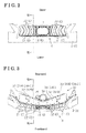
Fig. 3 is a plan view of the grille apparatus for a vehicle (fully-closed state) according to the embodiment; -
Fig. 4 is a perspective view of the grille apparatus for a vehicle (fully-closed state) according to the embodiment; -
Fig. 5 is a perspective view of the grille apparatus for a vehicle (fully-open state) according to the embodiment; -
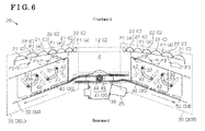
Fig. 6 is a view schematically illustrating a configuration of the grille apparatus for a vehicle according to the embodiment; -
Fig. 7 is an exploded perspective view of the grille apparatus for a vehicle according to the embodiment; -
Fig. 8 is a cross-sectional view of the grille apparatus which is taken along line VIII-VIII inFigs. 2 and 3 ; -
Fig. 9 is a cross-sectional view of the grille apparatus which is taken along line IX-IX inFig. 8 ; -
Fig. 10 is a cross-sectional view of the grille apparatus which is taken along line X-X inFig. 8 ; -
Fig. 11 is a cross-sectional view of the grille apparatus which is taken along line XI-XI inFig. 8 ; -
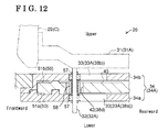
Fig. 12 is a cross-sectional view of the grille apparatus which is taken along line XII-XII inFigs. 9 ,10 and11 ; -
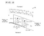
Fig. 13 is an explanatory view of an operation of the grille apparatus for a vehicle (fully-closed state) according to the embodiment; -
Fig. 14 is an explanatory view of the operation of the grille apparatus for a vehicle (moving state, or transitional state) according to the embodiment; and -
Fig. 15 is an explanatory view of the operation of the grille apparatus for a vehicle (fully-open state) according to the embodiment. - A
grille apparatus 20 for a vehicle according to an embodiment will be described referring to drawings. As illustrated inFig. 1 , afront grille 2 configuring a front design face S of avehicle 1 includes an opening portion of the front grille 2 (a grille opening portion 4) which connects an outer space at a front of thevehicle 1 and an inner space of avehicle body 3. Aradiator 7 is accommodated in anengine room 5 which is arranged at thevehicle body 3 to cool anengine 6. - Specifically, as illustrated in
Figs. 1 to 3 , thegrille opening portion 4 of the embodiment is arranged at a center in a width direction of the front grille 2 (left-right direction inFigs. 2 and 3 ) and, for details, thegrille opening portion 4 of the embodiment is arranged above a bumper 8 and abumper reinforcement 9. As illustrated inFig. 1 , theradiator 7 is arranged at a position frontward of theengine 6 in theengine room 5, the position where theradiator 7 receives air flowing via thegrille opening portion 4 into theengine room 5. - As illustrated in
Figs. 1 to 5 , according to the embodiment, plural cover members C are arranged inside thegrille opening portion 4. Thegrille opening portion 4 takes air flowing via clearances formed between each of the cover members C into theengine room 5. - In particular, a
center cover 12 is arranged inside thegrille opening portion 4 to close a center in a width direction of thegrille opening portion 4. Ahole portion 11 is formed at thecenter cover 12 of the embodiment for mounting an automobile emblem plate of thevehicle 1. Plural first covers 21 and plural second covers 22 are arranged at opposing sides in the width direction of thecenter cover 12.Figs. 4 and 5 illustrate a state where the first covers 21 and the second covers 22 arranged at one of the opposing sides in the width direction of the center cover 12 (at right inFigs. 4 and 5 ) are removed. Adrive mechanism 30 is positioned at a rear of the cover members C to change a relative position of the first covers 21 and the second covers 22 in response to a driving force of a motor 25 (serving as a drive source) as a drive source. - Further in detail, as illustrated in
Figs. 2 and 3 , the first covers 21 and the second covers 22 are extended in an up-down direction of the vehicle 1 (up-down direction inFig. 2 ) being formed in a three dimensional-shape such that each of middle portions in the up-down direction of the first covers 21 and the second covers 22 protrudes toward the center in the width direction of thegrille opening portion 4 and forward of thevehicle 1. The first covers 21 are arranged inside thegrille opening portion 4 to be spaced from one another in the width direction of thegrille opening portion 4. The second covers 22 are arranged inside thegrille opening portion 4 to be spaced from one another in the width direction of thegrille opening portion 4. According to the embodiment, for example, three each of the first covers 21 and the second covers 22 are arranged at each of the opposing sides in the width direction of thecenter cover 12. Thedrive mechanism 30 of the embodiment changes the relative position of the first covers 21 and the second covers 22 between a fully-closed state of thegrille apparatus 20 for a vehicle (fully-closed position P1) and a fully-open state of thegrille apparatus 20 for a vehicle (fully-open position P3). As illustrated inFig. 4 , the first covers 21 and the second covers 22 are arranged alternately in line in the width direction of thegrille opening portion 4 so that thegrille apparatus 20 for a vehicle is in the fully-closed state (fully-closed position P1). As illustrated inFig. 5 , the second covers 22 move to a rear of the respectivefirst covers 21 so that thegrille apparatus 20 for a vehicle is in the fully-open state (fully-open position P3). - As illustrated in
Fig. 6 , the size of the clearance formed between the cover members C is changed, or varied as the relative position offirst covers 21 and the second covers 22 is changed, or varied in thegrille opening portion 4. In particular, thegrille opening portion 4 is closed when the first covers 21 and the second covers 22 are arranged alternately in line. Opening areas α are formed between the first covers 21 adjacent to one another in the width direction of thegrille opening portion 4 as the second covers 22 move to the rear of the corresponding first covers 21. According to the embodiment, thegrille apparatus 20 for a vehicle is configured such that the opening amount of thefront grille 2 may be changed, or varied. - Next, a drive structure for opening and closing the cover members C of the
grille apparatus 20 for a vehicle according to the embodiment will be described. - According to the embodiment, the
center cover 12 and the first covers 21 are fixed to opposite open ends in the up-down direction of thegrille opening portion 4. As illustrated inFig. 6 , thedrive mechanism 30 may move the second covers 22 to the rear of the respectivefirst covers 21 which are adjacent to the second covers 22 in the fully-closed state of thegrille apparatus 20 for a vehicle by sliding the second covers 22 in a vehicle front-rear direction and in the width direction of thegrille opening portion 4. - Further in detail, as illustrated in
Fig. 7 , thedrive mechanism 30 of the embodiment includes a supportingmember 31, aguide protrusion 32, and abracket 34. The supportingmember 31 supports the second covers 22. Theguide protrusion 32 is mounted to the supportingmember 31. Thebracket 34 includes aguide groove 33 that engages with therespective guide protrusion 32. Thedrive mechanism 30 includes a drivingforce transmission mechanism 35 which transmits the driving force of themotor 25 to the supportingmember 31 to move the second covers 22 integrally with the supportingmember 31. - That is, the second covers 22 supported by the supporting
member 31 slide on a virtual plane orthogonal to an axial line of the shaft-shapedguide protrusion 32 when the supportingmember 31 is moved to change an engagement position of theguide protrusion 32 and theguide groove 33. According to the embodiment, a movement trajectory of the second cover 22 (and the supporting member 31) is determined by a groove shape of theguide groove 33. - As illustrated in
Figs. 6 and7 , themotor 25 as a drive source is arranged at a substantially center in the width direction of thegrille opening portion 4 and a rearward of thecenter cover 12. Themotor 25 is mounted with areduction gear 36 that reduces a rotational speed of themotor 25. Further, thegrille apparatus 20 for a vehicle of the embodiment includes the left-right pair of the drive mechanisms 30 (afirst drive mechanism 30L and asecond drive mechanism 30R) arranged to sandwich themotor 25 in the width direction of thegrille opening portion 4. Thesingle motor 25 drives the second covers 22 arranged at the opposing sides of thecenter cover 12 in the width direction of thegrille opening portion 4. - For convenience of explanation, a first side of the drive mechanisms 30 (the
second drive mechanism 30R) will be illustrated while a second side of the drive mechanisms 30 (thefirst drive mechanism 30L) will not be described. Further in detail, as illustrated inFigs. 7 and8 , thedrive mechanism 30 of the embodiment includes the upper-lower pair of the supporting members 31 (a first supportingmember 31A, a second supportingmember 31 B). The lower-arranged first supportingmember 31A supports alower end portion 22a of each of the second covers 22 while the upper-arranged second supportingmember 31B supports anupper end portion 22b of each of the second covers 22. Each of the supporting members 31 (the first supportingmember 31A, the second supportingmember 31 B) includes abase portion 31 a and plural (for example, three)branch portions 31 b. Thebase portion 31 a extends in the width direction of the grille opening portion 4 (left-right direction inFig. 7 ). Thebranch portions 31 b extend frontward in the vehicle front-rear direction from thebase portion 31 a so that front ends in the vehicle front-rear direction of thebranch portions 31b are fixed to the respective second covers 22. - Each of the supporting members 31 (the first supporting
member 31A, the second supportingmember 31 B) is arranged at alower end portion 4a (serving as an end portion) and anupper end portion 4b (serving as an end portion) of thegrille opening portion 4, respectively. Thelower end portion 4a and theupper end portion 4b are arranged at opposing ends of thegrille opening portion 4, the opposing ends orthogonal to the sliding direction of the second covers 22, that is, orthogonal to the width direction of thegrille opening portion 4 and orthogonal to the vehicle front-rear direction. The supporting members 31 (the first supportingmember 31A, the second supportingmember 31 B) are connected one another by a shaft-shapedconnection member 37 and are bridged between thebase portions 31 a of the supporting members 31 (the first supportingmember 31A, the second supportingmember 31 B). - According to the embodiment, the first supporting
member 31A supporting thelower end portions 22a of the second covers 22 includes shaft-shaped, plural (for example, two)first guide protrusions 32A protruding downward. At the lower of the first supportingmember 31A, afirst bracket 34A including pluralfirst guide grooves 33A (for example, two, for each of the first supportingmember 31A) engaging with thefirst guide protrusions 32A is provided. - In particular, the
first bracket 34A is formed such that afirst member 34a and asecond member 34b both formed in a substantially elongated flat plate are overlapped one another. As illustrated inFigs. 9 and10 , thefirst guide groove 33A includes oblong hole-shaped first and second throughholes first member 34a and thesecond member 34b, respectively. The first and second throughholes first member 34a and thesecond member 34b, respectively. - As illustrated in
Figs. 3 and7 , a second supportingmember 31B supporting theupper end portions 22b of the second covers 22 include shaft-shapedsecond guide protrusions 32B protruding upward. At the upper of the second supportingmember 31 B, asecond bracket 34B formed in an elongated flat plate-shape and includingsecond guide grooves 33B engaging with thesecond guide protrusions 32B is provided (upper inFig. 8 ). Thesecond guide grooves 33B include oblong hole-shaped third throughholes 38c penetrating in the thickness direction of thesecond bracket 34B. - According to the embodiment, the drive mechanisms 30 (the
first drive mechanism 30L and thesecond drive mechanism 30R) driving the second covers 22 which are arranged at the opposing sides in the width direction of thecenter cover 12 are formed integrally with thefirst bracket 34A (configured by thefirst member 34a and thesecond member 34b) and thesecond bracket 34B that are symmetrically connected. The lower-arrangedfirst bracket 34A and the upper-arrangedsecond bracket 34B are positioned at thelower end portion 4a and theupper end portion 4b of thegrille opening portion 4, respectively, in a substantially horizontal manner along with the width direction of thegrille opening portion 4 so that thefirst bracket 34A and thesecond bracket 34B are in parallel with one another. - As illustrated in
Figs. 6 and7 , the drivingforce transmission mechanism 35 of the embodiment includes a movingbody 40 and aconversion mechanism 41. The movingbody 40 is connected to the first supportingmember 31A. Theconversion mechanism 41 converts a rotation of themotor 25 as a drive source into a reciprocating movement of the movingbody 40. According to the embodiment, the second covers 22 supported by the first supportingmember 31A perform opening and closing operations as the first supportingmember 31A moves in response to the reciprocating movement of the movingbody 40. - Further in detail, as illustrated in
Fig. 11 , the movingbody 40 of the embodiment is formed in a substantially rectangular flat plate (formed in a slightly parallelogram shape). The movingbody 40 includes plural engaging recessedportions 42 engaging with thefirst guide protrusions 32A of the first supportingmember 31A. Specifically, the engaging recessedportions 42 include oblong hole-shaped fourth throughholes 38d penetrating in the thickness direction of the movingbody 40. The engaging recessedportion 42 and thefirst guide protrusion 32A are engaged with one another so that the movingbody 40 of the embodiment is connected to the first supportingmember 31A in a state where the first supportingmember 31A can move in response to the reciprocating movement of the movingbody 40. - As illustrated in
Fig. 6 , theconversion mechanism 41 of the embodiment is configured with apinion gear 44 rotated by a motor drive andrack belts 45 meshing with thepinion gear 44. That is, therack belt 45 is a rack gear made of a flexible material, for example, resin. Therack belt 45 meshes with thepinion gear 44 to be configured as a known rack and pinion mechanism. As illustrated inFig. 11 , an end in a longitudinal direction of therack belt 45 is fixed to alongitudinal side 40x of the movingbody 40. Accordingly, theconversion mechanism 41 of the embodiment allows the movingbody 40 to perform the reciprocating movement in a longitudinal direction of therack belt 45. - Further in detail, according to the embodiment, as illustrated in
Figs. 7 ,8 ,11 and12 , the lower-arrangedfirst bracket 34A includes astorage chamber 50 accommodating the movingbody 40 while allowing the reciprocating movement of the movingbody 40 along with the longitudinal direction of thefirst bracket 34A, that is, the width direction of the grille opening portion 4 (left-right direction inFig. 6 ). - In particular, according to the embodiment, as illustrated in
Figs. 6 ,7 , and12 , thefirst member 34a and thesecond member 34b configuring thefirst bracket 34A include slidable recessedportions body 40 and therack belt 45 are arranged. That is, according to the embodiment, as illustrated inFigs. 7 and12 , thefirst member 34a and thesecond member 34b are assembled so that thefirst member 34a and thesecond member 34b sandwich the moving body 40 (and the end in the longitudinal direction of the rack belt 45). Thestorage chamber 50 accommodating the movingbody 40 is formed with the slidable recessedportions portions - According to the embodiment, as illustrated in
Fig. 11 , thestorage chamber 50 includesopposite sidewalls opposite sidewalls first bracket 34A includes a guiding surface s1 on which the movingbody 40 slides inside thestorage chamber 50. According to the embodiment, the guide surface s1 configured with each of thesidewalls body 40 moves obliquely rearward in the vehicle front-rear direction when the movingbody 40 moves from the center to an outer portion in the width direction of thegrille opening portion 4. - According to the embodiment, as illustrated in
Fig. 12 , the first supportingmember 31A is assembled such that thefirst guide protrusion 32A protrudes downward of the first supportingmember 31A to penetrate the first throughhole 38a, the second throughhole 38b and the fourth throughhole 38d. The first throughhole 38a and the second throughhole 38b are arranged at thefirst member 34a and thesecond member 34b, respectively, of thefirst guide groove 33A of thefirst bracket 34A. The fourth throughhole 38d is arranged at the engaging recessedportion 42 of the movingbody 40. Thus, according to the embodiment, the second covers 22 supported by the first supportingmember 31A move in response to the reciprocating movement of the movingbody 40 inside thestorage chamber 50 by connecting the movingbody 40 to the first supportingmember 31A. - According to the embodiment, as illustrated in
Figs. 9 and10 , each of the first and second throughholes first guide groove 33A of thefirst bracket 34A is formed in a curved groove-shape and extended in the vehicle front-rear direction at the center in the width direction of thegrille opening portion 4 while extending in the width direction of thegrille opening portion 4 at an outer portion in the width direction of thegrille opening portion 4. Thesecond guide groove 33B of the upper-arrangedsecond bracket 34B is formed in the same curved groove-shape as thefirst guide groove 33A of thefirst bracket 34A. According to the embodiment, as illustrated inFig. 6 , thegrille apparatus 20 for a vehicle can perform the opening operation forming the opening areas α by moving the second covers 22 to the rear of the respective first covers 21 (fully-open position P3) without interfering the first covers 21 that are adjacent to the second covers 22 in the width direction of thegrille opening portion 4. Thegrille apparatus 20 for a vehicle can perform the closing operation by returning the relative position of the first covers 21 and the second covers 22 to the fully-closed position P1, the relative position before the second covers 22 move to the rear of the respective first covers 21. - According to the embodiment, as illustrated in
Fig. 11 , the engaging recessed portion 42 (the fourth throughhole 38d) of the movingbody 40 is formed such that thefirst guide protrusion 32A moves obliquely forward in the vehicle front-rear direction from the center to outward in the width direction of the grille opening portion 4 (up-down direction inFig. 11 ). That is, a wall surface of the engaging recessedportion 42 presses thefirst guide protrusion 32A in response to the reciprocating movement of the movingbody 40. The first supportingmember 31A and the second covers 22 move in response to the driving force transmitted via thefirst guide protrusion 32A. According to the embodiment, the driving force is transmitted efficiently by applying the oblong hole-shaped engaging recessedportion 42. - As illustrated in
Fig. 12 , thefirst guide protrusion 32A includesrollers 57 and 58 provided at positions where thefirst guide groove 33A and the engaging recessedportion 42 are engaged with thefirst guide protrusion 32A. Because therollers 57, 58 are slidably in contact with, and rotate on the wall surfaces of thefirst guide groove 33A and engaged recessedportion 42, a smooth movement of the second covers 22 is ensured. - Next, an operation (performance) of the
grille apparatus 20 for a vehicle configured as above will be described. As illustrated inFigs. 6 and13 to 15 , thegrille apparatus 20 for a vehicle of the embodiment performs the opening operation by moving the movingbody 40 from the center to the outer portion in the width direction of the grille opening portion 4 (from left to right inFigs. 13 to 15 ) in response to the driving force of themotor 25. Thegrille apparatus 20 for a vehicle performs the closing operation by moving the movingbody 40 from the outer portion to the center in the width direction of the grille opening portion 4 (from right to left inFigs. 13 to 15 ). - Specifically, as illustrated in
Fig. 13 , when thegrille apparatus 20 for a vehicle is in a fully-closed state (fully-closed position P1), the state where the first covers 21 and the second covers 22 are arranged alternately in line in the width direction of thegrille opening portion 4, the movingbody 40 arranged in thestorage chamber 50 of thefirst bracket 34A is positioned close to anend wall 50c arranged at the center in the width direction of the grille opening portion 4 (left inFig. 13 ). At this time, the guide protrusion 32 (32A) engaging with the guide groove 33 (33A) of the bracket 34 (34A) is positioned close to a center end of the guide groove 33 (33A) (left inFig. 13 ) in the width direction of thegrille opening portion 4. - As illustrated in
Figs. 14 and15 , when thegrille apparatus 20 for a vehicle performs the opening operation, theguide protrusion 32 engaging with theguide groove 33 moves from close to the center end to the outer end of theguide groove 33 in the width direction of thegrille opening portion 4 in response to a sliding movement of the movingbody 40 from close to the center end to the outer portion in the width direction of thegrille opening portion 4. Accordingly, the second covers 22 supported by the first supportingmember 31A move to the rear of the respectivefirst covers 21, which are adjacent to the second covers 22 in the width direction of thegrille opening portion 4. - As illustrated in
Figs. 13 to 15 , when thegrille apparatus 20 for a vehicle performs the closing operation, theguide protrusion 32 engaging with theguide groove 33 moves from close to the outer end to the center end of theguide groove 33 in the width direction of thegrille opening portion 4 in response to the sliding movement of the movingbody 40 from close to the outer end to close to the center end in the width direction of thegrille opening portion 4. Accordingly, the second covers 22 return to the position, the fully-closed position P1 where the opening areas α formed by the second covers 22 moving to the rear of the respectivefirst covers 21 are closed. - Further in detail, the second covers 22 move mainly in the vehicle front-rear direction of the
grille opening portion 4 to accord with a curved groove-shape of theguide groove 33 at a space close to the fully-closed position P1 where theguide protrusion 32 within theguide groove 33 moves between close to the center end and close to a middle portion of theguide groove 33 in the width direction of thegrille opening portion 4. The second covers 22 move mainly in the width direction of thegrille opening portion 4 to accord with the curved groove-shape of theguide groove 33 at a space close to the fully-open position P3 where theguide protrusion 32 within theguide groove 33 moves between close to the middle portion and close to the outer end of theguide groove 33 in the width direction of thegrille opening portion 4. - According to the embodiment, the sliding movement of the second covers 22 by the
drive mechanism 30 includes a movement of the second covers 22 to the rear in the vehicle front-rear direction from the fully-closed position P1 when the opening operation is performed. The sliding movement of the second covers 22 by thedrive mechanism 30 further includes a movement of the second covers 22 to a front in the vehicle front-rear direction to return to the fully-closed position P1 when the closing operation is performed (seeFigs. 13 and14 ). In other words, the second covers 22 slide in the width direction of thegrille opening portion 4 at the rear position in the vehicle front-rear direction without interfering the first covers 21 which are adjacent to the second covers 22. Accordingly, smooth opening and closing operations of thegrille apparatus 20 for a vehicle are secured. - An Engaging position of the engaging recessed
portion 42 of the movingbody 40 and theguide protrusion 32 moves from close to the outer end to close to the center ends of the engaging recessedportions 42 of the in the width direction of thegrille opening portion 4 when the opening operation is performed in response to the sliding movement of the movingbody 40. The engaging position of the engaging recessedportion 42 of the movingbody 40 and theguide protrusion 32 moves from close to the center end to close to the outer end of the engaging recessedportion 42 in the width direction of thegrille opening portion 4 when the closing operation is performed in response to the sliding movement of the movingbody 40. According to the embodiment, the wall surface of the engaging recessedportion 42 presses theguide protrusion 32 reliably. - The aforementioned embodiment may be changed, or modified as follows.
- According to the aforementioned embodiment, air flowing via the
grille opening portion 4 flows into theengine room 5 which is formed in thevehicle body 3. Alternatively, air flows into any inner space, for example, a housing of a heat exchanger such as theradiator 7 other than theengine room 5 as long as thegrille apparatus 20 for a vehicle includes a clearance where air flows via thegrille opening portion 4. The grille shutter apparatus 10 of the embodiment is applied to a vehicle in which an engine is arranged at a rear or a center of a vehicle body, or to a vehicle such as an electric vehicle in which an engine is not mounted on an frontward of a vehicle compartment of an inner body of a vehicle. - According to the aforementioned embodiment, each of the cover members C is arranged at the
grille opening portion 4 formed at an upper the bumper 8. Alternatively, thegrille opening portion 4 can be formed at a lower of the bumper 8. - According to the aforementioned embodiment, the first covers 21 and the second covers 22 are formed in the three-dimensional shape such that each of the middle portions in the vehicle up-down direction of the first covers 21 and the second covers 22 protrudes toward the center in the width direction of the
grille opening portion 4 and forward of thevehicle 1. Alternatively, the shapes of the cover members C including thecenter cover 12 are changed, or varied arbitrarily. - In addition, the number of the cover members C can be changed, or varied arbitrarily. For example, the same as the
center cover 12, the plural cover members C in which the second covers 22 do not move to the rear of the respectivefirst covers 21 may be provided. Alternatively, the cover members C, such as thecenter cover 12, that are not related to the opening and closing operation of thegrille opening portion 4 may not be provided. That is, thegrille apparatus 20 for a vehicle may include at least one of the first covers 21 maintained within thegrille opening portion 4 and at least one of the second covers 22 moving to the rear of the respectivefirst covers 21 within thegrille opening portion 4. - According to the aforementioned embodiment, when the
grille opening portion 4 is closed by the first covers 21 and the second covers 22 that are arranged adjacent to one another in line in the width direction of thegrille opening portion 4, the status can be defined as the fully-closed state of thegrille apparatus 20 for a vehicle. However, the first covers 21 and the second covers 22 are unnecessarily arranged in a straight line. The fully-closed state of thegrille apparatus 20 for a vehicle does not necessarily have to be a completely closed state in which no clearance for air flowing in is provided between the cover members C. - When the
grille apparatus 20 for a vehicle is in the fully-closed state, the first covers 21 and the second covers 22 may be arranged in parallel with one another in the up-down direction of thegrille opening portion 4. In this case, thedrive mechanism 30 is favorably arranged at a side end of thegrille opening portion 4. - When the
grille apparatus 20 for a vehicle is in the fully-open state, the second covers 22 do not necessarily have to move to the rear of the respectivefirst covers 21 completely as long as thegrille opening portion 4 includes new opening areas α that directly take air into the inner space of thevehicle body 3 without being interrupted by the cover members C at a front of thevehicle body 3. - According to the aforementioned embodiment, the
grille apparatus 20 for a vehicle performs opening and closing operations by sliding the second covers 22. Alternatively, the second covers 22 may, for example, rotate or incline to move to the rear of the respective first covers 21. The sliding movement of the second covers 22 may also include rotation and inclination. - According to the aforementioned embodiment, the first covers 21 are fixed to the opposite open ends in the up-down direction of the
grille opening portion 4. Alternatively, the first covers 21 may be moved including rotation and inclination as long as the first covers 21 and the second covers 22 are accommodated in thegrille opening portion 4 when thegrille apparatus 20 for a vehicle performs the opening operation. - According to the aforementioned embodiment, the
motor 25 is applied as a drive source. Alternatively, other drive sources including a solenoid may be applied as a drive source. - According to the aforementioned embodiment, the
motor 25 as the drive source is arranged at a substantially center in the width direction of thegrille opening portion 4. Thegrille apparatus 20 for a vehicle includes the left-right pair of the drive mechanisms 30 (thefirst drive mechanism 30L and thesecond drive mechanism 30R) arranged to sandwich themotor 25 in the width direction of thegrille opening portion 4. Alternatively, a drive source may be positioned arbitrarily. For example, themotor 25 may be arranged at a side end in the width direction of thegrille opening portion 4. In this case, all the second covers 22 may be driven by thesingle drive mechanism 30. Further, themotor 25 may be arranged at a position where the drive mechanisms 30 (thefirst drive mechanism 30L and thesecond drive mechanism 30R) are positioned asymmetrically relative to themotor 25. - According to the aforementioned embodiment, the
drive mechanism 30 includes an up-down pair of the supporting members 31 (the first supportingmember 31A, the second supportingmember 31 B). The lower-arranged first supportingmember 31A supports thelower end portions 22a of the second covers 22 while the upper-arranged second supportingmember 31B supports theupper end portions 22b of the second covers 22. Alternatively, thedrive mechanism 30 may include the single supportingmember 31 and thesingle bracket 34 corresponding to the supportingmember 31. - Further, alternatively, each of the supporting members 31 (the first supporting
member 31A, the second supportingmember 31 B) supporting the second covers 22 may include the drivingforce transmission mechanism 35. - The number of the
guide protrusion 32 mounted to the supportingmember 31 and the number of theguide groove 33 which is provided at thebracket 34 and engages with theguide protrusion 32 may be changed, or varied arbitrarily. The shape of theguide protrusion 32 may be changed, or varied arbitrarily. Further, the groove shape of theguide protrusion 32 determining a movement trajectory of each of the second covers 22 (and the supporting member 31) may be changed, or varied arbitrarily. - According to the aforementioned embodiment, the driving
force transmission mechanism 35 includes the movingbody 40 connected to the first supportingmember 31A and theconversion mechanism 41 converting the rotational movement of themotor 25 as a drive source into the reciprocating movement of the movingbody 40. According to the embodiment, the rack and pinion mechanism (thepinion gear 44 and the rack belt 45) is applied as theconversion mechanism 41. Alternatively, the structure of theconversion mechanism 41 may be arbitrarily changed, or varied as long as a mechanism can move the second covers 22 integrally with the supportingmember 31 by transmitting a driving force of themotor 25 to the supportingmember 31. For example, a ball screw mechanism may be applied. - According to the aforementioned embodiment, the bracket 34 (34A) includes the
storage chamber 50 in which the movingbody 40 is slidably accommodated. Alternatively, the position of the movingbody 40 may be changed, or varied arbitrarily. - According to the aforementioned embodiment, the
bracket 34 and the movingbody 40 are formed in substantially flat plate-shapes. Alternatively, the shapes of thebracket 34 and the movingbody 40 may be changed, or varied arbitrarily. - According to the aforementioned embodiment, the
first bracket 34A is formed such that thefirst member 34a and thesecond member 34b both formed in the substantially elongated flat plate are overlapped one another. Alternatively, thefirst bracket 34A may be configured with a single member. - The linking structure of the moving
body 40 and the supportingmember 31 may be changed, or varied arbitrarily. For example, the movingbody 40 may be directly connected to the supportingmember 31. In a case where a linking structure in which the guide protrusion 32 (32A) and the engaging recessedportion 42 are connected is adopted, the shape of the engaging recessedportion 42 may be changed, or varied arbitrarily.
Claims (11)
- A grille apparatus (20) for a vehicle, comprising:a first cover (21) arranged at an opening portion of a front grille (2);a second cover (22) arranged at the opening portion of the front grille (2); anda drive mechanism (30) changing a relative position of the first cover (21) and the second cover (22) in response to a driving force of a drive source (25), wherein the drive mechanism (30) changes an opening amount of the front grille (2) by performing an opening operation moving the second cover (22) to a rear of the first cover (21), and by performing a closing operation returning the second cover (22) to a fully-closed position (P1), the fully-closed position (P1) before moving the second cover (22) to the rear of the first cover (21) while maintaining the first cover (21) and the second cover (22) within the opening portion of the front grille (2).
- The grille apparatus (20) for a vehicle according to claim 1, wherein the opening operation and the closing operation are performed by a sliding movement of the second cover (22).
- The grille apparatus (20) for a vehicle according to claim 2, wherein the sliding movement includes a movement of the second cover (22) to a rear in a vehicle front-rear direction from the fully-closed position (P1) when the opening operation is performed, and a movement of the second cover (22) to a front in the vehicle front-rear direction to return to the fully-closed position (P1) when the closing operation is performed.
- The grille apparatus (20) for a vehicle according to either claim 2 or 3, wherein the drive mechanism (30) includes a supporting member (31, 31A, 31B) supporting the second cover (22), a guide protrusion (32, 32A, 32B) provided at the supporting member (31, 31A, 31 B), a bracket (34, 34A, 34B) including a guide groove (33, 33A, 33B) engaging with the guide protrusion (32, 32A, 32B), and a driving force transmission mechanism (35) moving the second cover (22) integrally with the supporting member (31, 31A, 31 B) by transmitting the driving force of the drive source (25) to the supporting member (31, 31A, 31 B).
- The grille apparatus (20) for a vehicle according to claim 4, wherein the drive mechanism (30) is arranged at an end portion (4a) of the opening portion of the front grille (2) in a direction intersecting a sliding movement direction of the second cover (22) within the opening portion of the front grille (2).
- The grille apparatus (20) for a vehicle according to either claim 4 or 5, wherein the driving force transmission mechanism (35) includes a moving body (40) connected to the supporting member (31, 31A, 31 B) and a conversion mechanism (41) converting the driving force of the drive source (25) into a reciprocating movement of the moving body (40).
- The grille apparatus (20) for a vehicle according to claim 6, wherein the bracket (34, 34A, 34B) includes a storage chamber (50) slidably accommodating the moving body (40).
- The grille apparatus (20) for a vehicle according to claim 6, wherein the moving body (40) includes an engaging recessed portion (42) engaging with the guide protrusion (32, 32A, 32B) to be connected to the supporting member (31, 31A, 31 B).
- The grille apparatus (20) for a vehicle according to any one of claims 1 to 7, wherein a plurality of the first covers (21) and a plurality of the second covers (22) are arranged alternately in line when the second cover (22) is in the fully-closed position (P1).
- The grille apparatus (20) for a vehicle according to any one of claims 1 to 8 wherein the drive mechanism (30) includes a first drive mechanism (30L) and a second drive mechanism (30R) that are arranged at positions to sandwich the drive source (25).
- The grille apparatus (20) for a vehicle according to any one of claims 1 to 9, wherein the first cover (21) and the second cover (22) are arranged alternately in line in the width direction of the opening portion of the front grille (2) when the second cover (22) is in the fully-closed position (P1).
Applications Claiming Priority (1)
| Application Number | Priority Date | Filing Date | Title |
|---|---|---|---|
| JP2013002960A JP6089708B2 (en) | 2013-01-10 | 2013-01-10 | Grill device for vehicle |
Publications (2)
| Publication Number | Publication Date |
|---|---|
| EP2754579A1 true EP2754579A1 (en) | 2014-07-16 |
| EP2754579B1 EP2754579B1 (en) | 2016-06-08 |
Family
ID=49918554
Family Applications (1)
| Application Number | Title | Priority Date | Filing Date |
|---|---|---|---|
| EP14150621.2A Not-in-force EP2754579B1 (en) | 2013-01-10 | 2014-01-09 | Grille apparatus for vehicle |
Country Status (3)
| Country | Link |
|---|---|
| US (1) | US9533564B2 (en) |
| EP (1) | EP2754579B1 (en) |
| JP (1) | JP6089708B2 (en) |
Cited By (2)
| Publication number | Priority date | Publication date | Assignee | Title |
|---|---|---|---|---|
| FR3029858A1 (en) * | 2014-12-16 | 2016-06-17 | Electricfil Automotive | DEVICE FOR CONTROLLING SHUTTERS BY A LINEAR ACTUATOR |
| EP4011673A3 (en) * | 2020-12-08 | 2022-11-09 | Hyundai Mobis Co., Ltd. | Active air flap apparatus for vehicle |
Families Citing this family (12)
| Publication number | Priority date | Publication date | Assignee | Title |
|---|---|---|---|---|
| DE102011113907A1 (en) * | 2011-09-21 | 2012-04-05 | Daimler Ag | Covering for driving cab of motor vehicle, particularly commercial vehicle, has covering element, which is adjusted from covering position into further position |
| US9533565B2 (en) * | 2013-02-05 | 2017-01-03 | Montaplast of North America, Inc. | Active grille shutter assembly |
| US20140273807A1 (en) * | 2013-03-15 | 2014-09-18 | Srg Global , Inc. | Grille Shutter Assembly |
| US9758031B2 (en) * | 2013-11-23 | 2017-09-12 | Daimler Ag | Radiator grille arrangement for a vehicle |
| JP2015214211A (en) | 2014-05-09 | 2015-12-03 | アイシン精機株式会社 | Grille device for vehicle |
| DE202014103672U1 (en) * | 2014-08-07 | 2015-11-10 | Reum Kunststoff- Und Metalltechnik Gmbh | aeration device |
| US9744847B2 (en) * | 2015-07-20 | 2017-08-29 | Ford Global Technologies, Llc | Flush mount active grille shutter and actuator |
| US10100707B2 (en) | 2016-02-29 | 2018-10-16 | Montaplast of North America, Inc. | Active grille shutter and shutter subassembly for use with active grill shutters |
| DE102016209156A1 (en) * | 2016-05-25 | 2017-11-30 | Magna Exteriors Gmbh | Flap system for the control of vehicle cooling |
| KR101876074B1 (en) * | 2016-11-11 | 2018-07-06 | 현대자동차주식회사 | Active air flap opening and closing during fault |
| KR20240054721A (en) * | 2022-10-19 | 2024-04-26 | 현대자동차주식회사 | Variable type grille apparatus |
| FR3145703A1 (en) * | 2023-02-15 | 2024-08-16 | Renault S.A.S | Motor vehicle grille with adjustable air intake |
Citations (5)
| Publication number | Priority date | Publication date | Assignee | Title |
|---|---|---|---|---|
| DE3151435A1 (en) * | 1980-12-26 | 1982-07-08 | Nissan Motor Co., Ltd., Yokohama, Kanagawa | "RADIATOR GRILL FOR MOTOR VEHICLES" |
| DE102006053883A1 (en) * | 2006-11-14 | 2008-05-15 | Friedrich Graepel Ag | Radiator component for vehicle, has device for influencing amount of air flowing through radiator component, and comprising two modular sheets spaced apart from each other and arranged at radiator and/or intercooler |
| DE202011000454U1 (en) * | 2011-02-28 | 2011-05-05 | Dr. Schneider Kunststoffwerke Gmbh | Throttling device for the air flow through an air inlet |
| US20120074729A1 (en) * | 2010-09-27 | 2012-03-29 | Srg Global, Inc. | Shutter System for Vehicle Grille |
| JP2012148705A (en) | 2011-01-20 | 2012-08-09 | Aisin Seiki Co Ltd | Air intake opening and closing apparatus for vehicle |
Family Cites Families (11)
| Publication number | Priority date | Publication date | Assignee | Title |
|---|---|---|---|---|
| JPS55142328U (en) * | 1979-02-28 | 1980-10-11 | ||
| JPS58139519U (en) | 1982-03-17 | 1983-09-20 | 三菱自動車工業株式会社 | grill opening/closing device |
| JPS60106860U (en) * | 1983-12-27 | 1985-07-20 | 関東自動車工業株式会社 | car grill equipment |
| DE102004026419B4 (en) | 2004-05-29 | 2025-12-18 | Bayerische Motoren Werke Aktiengesellschaft | Device for adjusting the airflow through inlet openings provided in the front area of a motor vehicle, in particular for adjusting the airflow to an engine compartment of a motor vehicle. |
| US20070077880A1 (en) * | 2005-10-03 | 2007-04-05 | Focxonn Technology Co., Ltd. | Computer system airflow-guiding device |
| DE102008049010A1 (en) * | 2008-09-25 | 2010-04-01 | Dr.Ing.H.C.F.Porsche Aktiengesellschaft | Device for supplying cooling air to a vehicle radiator of a motor vehicle |
| JP5267156B2 (en) * | 2009-01-23 | 2013-08-21 | トヨタ自動車株式会社 | Vehicle radiator grille structure |
| JP2010223150A (en) * | 2009-03-25 | 2010-10-07 | Aisin Seiki Co Ltd | Movable grill shutter for vehicles |
| US20110005851A1 (en) * | 2009-07-13 | 2011-01-13 | Doroghazi William J | Vehicle grille including adjustable louvers, and/or method of making the same |
| US8550887B2 (en) * | 2009-09-18 | 2013-10-08 | Lacks Enterprises, Inc. | Vehicle grill with moveable louvers |
| KR101163447B1 (en) * | 2009-09-30 | 2012-07-18 | 주식회사 에스에이치비 | Automobile air flap opening and closing apparatus |
-
2013
- 2013-01-10 JP JP2013002960A patent/JP6089708B2/en not_active Expired - Fee Related
- 2013-12-19 US US14/133,846 patent/US9533564B2/en active Active
-
2014
- 2014-01-09 EP EP14150621.2A patent/EP2754579B1/en not_active Not-in-force
Patent Citations (5)
| Publication number | Priority date | Publication date | Assignee | Title |
|---|---|---|---|---|
| DE3151435A1 (en) * | 1980-12-26 | 1982-07-08 | Nissan Motor Co., Ltd., Yokohama, Kanagawa | "RADIATOR GRILL FOR MOTOR VEHICLES" |
| DE102006053883A1 (en) * | 2006-11-14 | 2008-05-15 | Friedrich Graepel Ag | Radiator component for vehicle, has device for influencing amount of air flowing through radiator component, and comprising two modular sheets spaced apart from each other and arranged at radiator and/or intercooler |
| US20120074729A1 (en) * | 2010-09-27 | 2012-03-29 | Srg Global, Inc. | Shutter System for Vehicle Grille |
| JP2012148705A (en) | 2011-01-20 | 2012-08-09 | Aisin Seiki Co Ltd | Air intake opening and closing apparatus for vehicle |
| DE202011000454U1 (en) * | 2011-02-28 | 2011-05-05 | Dr. Schneider Kunststoffwerke Gmbh | Throttling device for the air flow through an air inlet |
Cited By (4)
| Publication number | Priority date | Publication date | Assignee | Title |
|---|---|---|---|---|
| FR3029858A1 (en) * | 2014-12-16 | 2016-06-17 | Electricfil Automotive | DEVICE FOR CONTROLLING SHUTTERS BY A LINEAR ACTUATOR |
| WO2016097589A1 (en) | 2014-12-16 | 2016-06-23 | Electricfil Automotive | Device for controlling flaps via a linear actuator |
| EP4011673A3 (en) * | 2020-12-08 | 2022-11-09 | Hyundai Mobis Co., Ltd. | Active air flap apparatus for vehicle |
| US11639099B2 (en) | 2020-12-08 | 2023-05-02 | Hyundai Mobis Co., Ltd. | Active air flap apparatus for vehicle |
Also Published As
| Publication number | Publication date |
|---|---|
| JP2014133491A (en) | 2014-07-24 |
| US9533564B2 (en) | 2017-01-03 |
| US20140194052A1 (en) | 2014-07-10 |
| EP2754579B1 (en) | 2016-06-08 |
| JP6089708B2 (en) | 2017-03-08 |
Similar Documents
| Publication | Publication Date | Title |
|---|---|---|
| US9533564B2 (en) | Grille apparatus for vehicle | |
| CN106143124B (en) | External activity air door for vehicle motor room | |
| EP2942221A2 (en) | Vehicle grille apparatus | |
| CN115805803A (en) | Active Air Dampers for Vehicles | |
| EP2641768A1 (en) | Grill shutter device | |
| CN105377608B (en) | Grid covers component | |
| CN106715176B (en) | Air-inlet grille module | |
| CN103476617B (en) | Drive system for multiple movable systems | |
| CN218400200U (en) | Active air damper for vehicle | |
| EP2574484A1 (en) | Grille shutter device | |
| US20170080794A1 (en) | Vehicular shutter device | |
| EP2407333A1 (en) | Movable grille shutter for vehicle | |
| US8292359B2 (en) | Roof apparatus for vehicle | |
| US20120186890A1 (en) | Air intake opening and closing apparatus for vehicle | |
| CN218400199U (en) | Active air damper for vehicle | |
| EP4067136A1 (en) | Slim air vent for vehicle | |
| CN114056080A (en) | Initiative air-inlet grille subassembly and vehicle front end module | |
| US9358915B2 (en) | Storage assembly for vehicle | |
| KR102639724B1 (en) | Glove box apparatus | |
| KR20150070769A (en) | Active Air Flap | |
| JP6463643B2 (en) | Vehicle shutter opening / closing mechanism | |
| CN113619358B (en) | Air outlet assembly for vehicle and vehicle with same | |
| CN204176864U (en) | Air-conditioner | |
| CN210852039U (en) | Blocking device for an air inlet of a front face of a motor vehicle | |
| EP3168073B1 (en) | Moving device |
Legal Events
| Date | Code | Title | Description |
|---|---|---|---|
| PUAI | Public reference made under article 153(3) epc to a published international application that has entered the european phase |
Free format text: ORIGINAL CODE: 0009012 |
|
| 17P | Request for examination filed |
Effective date: 20140109 |
|
| AK | Designated contracting states |
Kind code of ref document: A1 Designated state(s): AL AT BE BG CH CY CZ DE DK EE ES FI FR GB GR HR HU IE IS IT LI LT LU LV MC MK MT NL NO PL PT RO RS SE SI SK SM TR |
|
| AX | Request for extension of the european patent |
Extension state: BA ME |
|
| R17P | Request for examination filed (corrected) |
Effective date: 20141009 |
|
| RBV | Designated contracting states (corrected) |
Designated state(s): AL AT BE BG CH CY CZ DE DK EE ES FI FR GB GR HR HU IE IS IT LI LT LU LV MC MK MT NL NO PL PT RO RS SE SI SK SM TR |
|
| GRAP | Despatch of communication of intention to grant a patent |
Free format text: ORIGINAL CODE: EPIDOSNIGR1 |
|
| RIC1 | Information provided on ipc code assigned before grant |
Ipc: B60K 11/08 20060101AFI20151106BHEP |
|
| INTG | Intention to grant announced |
Effective date: 20151215 |
|
| GRAS | Grant fee paid |
Free format text: ORIGINAL CODE: EPIDOSNIGR3 |
|
| GRAA | (expected) grant |
Free format text: ORIGINAL CODE: 0009210 |
|
| AK | Designated contracting states |
Kind code of ref document: B1 Designated state(s): AL AT BE BG CH CY CZ DE DK EE ES FI FR GB GR HR HU IE IS IT LI LT LU LV MC MK MT NL NO PL PT RO RS SE SI SK SM TR |
|
| REG | Reference to a national code |
Ref country code: GB Ref legal event code: FG4D |
|
| REG | Reference to a national code |
Ref country code: CH Ref legal event code: EP |
|
| REG | Reference to a national code |
Ref country code: IE Ref legal event code: FG4D |
|
| REG | Reference to a national code |
Ref country code: AT Ref legal event code: REF Ref document number: 804952 Country of ref document: AT Kind code of ref document: T Effective date: 20160715 |
|
| REG | Reference to a national code |
Ref country code: DE Ref legal event code: R096 Ref document number: 602014002211 Country of ref document: DE |
|
| REG | Reference to a national code |
Ref country code: FR Ref legal event code: PLFP Year of fee payment: 4 |
|
| REG | Reference to a national code |
Ref country code: LT Ref legal event code: MG4D |
|
| REG | Reference to a national code |
Ref country code: NL Ref legal event code: MP Effective date: 20160608 |
|
| PG25 | Lapsed in a contracting state [announced via postgrant information from national office to epo] |
Ref country code: FI Free format text: LAPSE BECAUSE OF FAILURE TO SUBMIT A TRANSLATION OF THE DESCRIPTION OR TO PAY THE FEE WITHIN THE PRESCRIBED TIME-LIMIT Effective date: 20160608 Ref country code: LT Free format text: LAPSE BECAUSE OF FAILURE TO SUBMIT A TRANSLATION OF THE DESCRIPTION OR TO PAY THE FEE WITHIN THE PRESCRIBED TIME-LIMIT Effective date: 20160608 Ref country code: NO Free format text: LAPSE BECAUSE OF FAILURE TO SUBMIT A TRANSLATION OF THE DESCRIPTION OR TO PAY THE FEE WITHIN THE PRESCRIBED TIME-LIMIT Effective date: 20160908 |
|
| REG | Reference to a national code |
Ref country code: AT Ref legal event code: MK05 Ref document number: 804952 Country of ref document: AT Kind code of ref document: T Effective date: 20160608 |
|
| PG25 | Lapsed in a contracting state [announced via postgrant information from national office to epo] |
Ref country code: LV Free format text: LAPSE BECAUSE OF FAILURE TO SUBMIT A TRANSLATION OF THE DESCRIPTION OR TO PAY THE FEE WITHIN THE PRESCRIBED TIME-LIMIT Effective date: 20160608 Ref country code: GR Free format text: LAPSE BECAUSE OF FAILURE TO SUBMIT A TRANSLATION OF THE DESCRIPTION OR TO PAY THE FEE WITHIN THE PRESCRIBED TIME-LIMIT Effective date: 20160909 Ref country code: NL Free format text: LAPSE BECAUSE OF FAILURE TO SUBMIT A TRANSLATION OF THE DESCRIPTION OR TO PAY THE FEE WITHIN THE PRESCRIBED TIME-LIMIT Effective date: 20160608 Ref country code: HR Free format text: LAPSE BECAUSE OF FAILURE TO SUBMIT A TRANSLATION OF THE DESCRIPTION OR TO PAY THE FEE WITHIN THE PRESCRIBED TIME-LIMIT Effective date: 20160608 Ref country code: RS Free format text: LAPSE BECAUSE OF FAILURE TO SUBMIT A TRANSLATION OF THE DESCRIPTION OR TO PAY THE FEE WITHIN THE PRESCRIBED TIME-LIMIT Effective date: 20160608 Ref country code: SE Free format text: LAPSE BECAUSE OF FAILURE TO SUBMIT A TRANSLATION OF THE DESCRIPTION OR TO PAY THE FEE WITHIN THE PRESCRIBED TIME-LIMIT Effective date: 20160608 Ref country code: ES Free format text: LAPSE BECAUSE OF FAILURE TO SUBMIT A TRANSLATION OF THE DESCRIPTION OR TO PAY THE FEE WITHIN THE PRESCRIBED TIME-LIMIT Effective date: 20160608 |
|
| PG25 | Lapsed in a contracting state [announced via postgrant information from national office to epo] |
Ref country code: IT Free format text: LAPSE BECAUSE OF FAILURE TO SUBMIT A TRANSLATION OF THE DESCRIPTION OR TO PAY THE FEE WITHIN THE PRESCRIBED TIME-LIMIT Effective date: 20160608 Ref country code: CZ Free format text: LAPSE BECAUSE OF FAILURE TO SUBMIT A TRANSLATION OF THE DESCRIPTION OR TO PAY THE FEE WITHIN THE PRESCRIBED TIME-LIMIT Effective date: 20160608 Ref country code: RO Free format text: LAPSE BECAUSE OF FAILURE TO SUBMIT A TRANSLATION OF THE DESCRIPTION OR TO PAY THE FEE WITHIN THE PRESCRIBED TIME-LIMIT Effective date: 20160608 Ref country code: SK Free format text: LAPSE BECAUSE OF FAILURE TO SUBMIT A TRANSLATION OF THE DESCRIPTION OR TO PAY THE FEE WITHIN THE PRESCRIBED TIME-LIMIT Effective date: 20160608 Ref country code: EE Free format text: LAPSE BECAUSE OF FAILURE TO SUBMIT A TRANSLATION OF THE DESCRIPTION OR TO PAY THE FEE WITHIN THE PRESCRIBED TIME-LIMIT Effective date: 20160608 Ref country code: IS Free format text: LAPSE BECAUSE OF FAILURE TO SUBMIT A TRANSLATION OF THE DESCRIPTION OR TO PAY THE FEE WITHIN THE PRESCRIBED TIME-LIMIT Effective date: 20161008 |
|
| PG25 | Lapsed in a contracting state [announced via postgrant information from national office to epo] |
Ref country code: AT Free format text: LAPSE BECAUSE OF FAILURE TO SUBMIT A TRANSLATION OF THE DESCRIPTION OR TO PAY THE FEE WITHIN THE PRESCRIBED TIME-LIMIT Effective date: 20160608 Ref country code: BE Free format text: LAPSE BECAUSE OF FAILURE TO SUBMIT A TRANSLATION OF THE DESCRIPTION OR TO PAY THE FEE WITHIN THE PRESCRIBED TIME-LIMIT Effective date: 20160608 Ref country code: PT Free format text: LAPSE BECAUSE OF FAILURE TO SUBMIT A TRANSLATION OF THE DESCRIPTION OR TO PAY THE FEE WITHIN THE PRESCRIBED TIME-LIMIT Effective date: 20161010 Ref country code: PL Free format text: LAPSE BECAUSE OF FAILURE TO SUBMIT A TRANSLATION OF THE DESCRIPTION OR TO PAY THE FEE WITHIN THE PRESCRIBED TIME-LIMIT Effective date: 20160608 Ref country code: SM Free format text: LAPSE BECAUSE OF FAILURE TO SUBMIT A TRANSLATION OF THE DESCRIPTION OR TO PAY THE FEE WITHIN THE PRESCRIBED TIME-LIMIT Effective date: 20160608 |
|
| REG | Reference to a national code |
Ref country code: DE Ref legal event code: R097 Ref document number: 602014002211 Country of ref document: DE |
|
| PLBE | No opposition filed within time limit |
Free format text: ORIGINAL CODE: 0009261 |
|
| STAA | Information on the status of an ep patent application or granted ep patent |
Free format text: STATUS: NO OPPOSITION FILED WITHIN TIME LIMIT |
|
| 26N | No opposition filed |
Effective date: 20170309 |
|
| PG25 | Lapsed in a contracting state [announced via postgrant information from national office to epo] |
Ref country code: SI Free format text: LAPSE BECAUSE OF FAILURE TO SUBMIT A TRANSLATION OF THE DESCRIPTION OR TO PAY THE FEE WITHIN THE PRESCRIBED TIME-LIMIT Effective date: 20160608 Ref country code: DK Free format text: LAPSE BECAUSE OF FAILURE TO SUBMIT A TRANSLATION OF THE DESCRIPTION OR TO PAY THE FEE WITHIN THE PRESCRIBED TIME-LIMIT Effective date: 20160608 |
|
| REG | Reference to a national code |
Ref country code: CH Ref legal event code: PL |
|
| PG25 | Lapsed in a contracting state [announced via postgrant information from national office to epo] |
Ref country code: MC Free format text: LAPSE BECAUSE OF FAILURE TO SUBMIT A TRANSLATION OF THE DESCRIPTION OR TO PAY THE FEE WITHIN THE PRESCRIBED TIME-LIMIT Effective date: 20160608 |
|
| PG25 | Lapsed in a contracting state [announced via postgrant information from national office to epo] |
Ref country code: CH Free format text: LAPSE BECAUSE OF NON-PAYMENT OF DUE FEES Effective date: 20170131 Ref country code: LI Free format text: LAPSE BECAUSE OF NON-PAYMENT OF DUE FEES Effective date: 20170131 |
|
| REG | Reference to a national code |
Ref country code: IE Ref legal event code: MM4A |
|
| PG25 | Lapsed in a contracting state [announced via postgrant information from national office to epo] |
Ref country code: LU Free format text: LAPSE BECAUSE OF NON-PAYMENT OF DUE FEES Effective date: 20170109 |
|
| REG | Reference to a national code |
Ref country code: FR Ref legal event code: PLFP Year of fee payment: 5 |
|
| PG25 | Lapsed in a contracting state [announced via postgrant information from national office to epo] |
Ref country code: IE Free format text: LAPSE BECAUSE OF NON-PAYMENT OF DUE FEES Effective date: 20170109 |
|
| GBPC | Gb: european patent ceased through non-payment of renewal fee |
Effective date: 20180109 |
|
| PG25 | Lapsed in a contracting state [announced via postgrant information from national office to epo] |
Ref country code: MT Free format text: LAPSE BECAUSE OF NON-PAYMENT OF DUE FEES Effective date: 20170109 |
|
| PG25 | Lapsed in a contracting state [announced via postgrant information from national office to epo] |
Ref country code: AL Free format text: LAPSE BECAUSE OF FAILURE TO SUBMIT A TRANSLATION OF THE DESCRIPTION OR TO PAY THE FEE WITHIN THE PRESCRIBED TIME-LIMIT Effective date: 20160608 |
|
| PG25 | Lapsed in a contracting state [announced via postgrant information from national office to epo] |
Ref country code: GB Free format text: LAPSE BECAUSE OF NON-PAYMENT OF DUE FEES Effective date: 20180109 |
|
| PG25 | Lapsed in a contracting state [announced via postgrant information from national office to epo] |
Ref country code: HU Free format text: LAPSE BECAUSE OF FAILURE TO SUBMIT A TRANSLATION OF THE DESCRIPTION OR TO PAY THE FEE WITHIN THE PRESCRIBED TIME-LIMIT; INVALID AB INITIO Effective date: 20140109 |
|
| PG25 | Lapsed in a contracting state [announced via postgrant information from national office to epo] |
Ref country code: BG Free format text: LAPSE BECAUSE OF FAILURE TO SUBMIT A TRANSLATION OF THE DESCRIPTION OR TO PAY THE FEE WITHIN THE PRESCRIBED TIME-LIMIT Effective date: 20160608 |
|
| PG25 | Lapsed in a contracting state [announced via postgrant information from national office to epo] |
Ref country code: CY Free format text: LAPSE BECAUSE OF NON-PAYMENT OF DUE FEES Effective date: 20160608 |
|
| PG25 | Lapsed in a contracting state [announced via postgrant information from national office to epo] |
Ref country code: MK Free format text: LAPSE BECAUSE OF FAILURE TO SUBMIT A TRANSLATION OF THE DESCRIPTION OR TO PAY THE FEE WITHIN THE PRESCRIBED TIME-LIMIT Effective date: 20160608 |
|
| PG25 | Lapsed in a contracting state [announced via postgrant information from national office to epo] |
Ref country code: TR Free format text: LAPSE BECAUSE OF FAILURE TO SUBMIT A TRANSLATION OF THE DESCRIPTION OR TO PAY THE FEE WITHIN THE PRESCRIBED TIME-LIMIT Effective date: 20160608 |
|
| PGFP | Annual fee paid to national office [announced via postgrant information from national office to epo] |
Ref country code: FR Payment date: 20201210 Year of fee payment: 8 |
|
| PGFP | Annual fee paid to national office [announced via postgrant information from national office to epo] |
Ref country code: DE Payment date: 20201229 Year of fee payment: 8 |
|
| REG | Reference to a national code |
Ref country code: DE Ref legal event code: R119 Ref document number: 602014002211 Country of ref document: DE |
|
| PG25 | Lapsed in a contracting state [announced via postgrant information from national office to epo] |
Ref country code: DE Free format text: LAPSE BECAUSE OF NON-PAYMENT OF DUE FEES Effective date: 20220802 |
|
| PG25 | Lapsed in a contracting state [announced via postgrant information from national office to epo] |
Ref country code: FR Free format text: LAPSE BECAUSE OF NON-PAYMENT OF DUE FEES Effective date: 20220131 |