EP2754561A1 - Liquid discharging apparatus - Google Patents
Liquid discharging apparatus Download PDFInfo
- Publication number
- EP2754561A1 EP2754561A1 EP20140151091 EP14151091A EP2754561A1 EP 2754561 A1 EP2754561 A1 EP 2754561A1 EP 20140151091 EP20140151091 EP 20140151091 EP 14151091 A EP14151091 A EP 14151091A EP 2754561 A1 EP2754561 A1 EP 2754561A1
- Authority
- EP
- European Patent Office
- Prior art keywords
- medium
- roll
- target portion
- sensing
- sensing target
- Prior art date
- Legal status (The legal status is an assumption and is not a legal conclusion. Google has not performed a legal analysis and makes no representation as to the accuracy of the status listed.)
- Granted
Links
- 239000007788 liquid Substances 0.000 title claims abstract description 65
- 238000007599 discharging Methods 0.000 title claims abstract description 28
- 230000005855 radiation Effects 0.000 claims abstract description 30
- 238000010438 heat treatment Methods 0.000 claims description 13
- 229910052782 aluminium Inorganic materials 0.000 claims description 7
- XAGFODPZIPBFFR-UHFFFAOYSA-N aluminium Chemical compound [Al] XAGFODPZIPBFFR-UHFFFAOYSA-N 0.000 claims description 7
- 238000004804 winding Methods 0.000 description 41
- 239000000976 ink Substances 0.000 description 28
- 230000032258 transport Effects 0.000 description 23
- 239000011347 resin Substances 0.000 description 18
- 229920005989 resin Polymers 0.000 description 18
- 239000000463 material Substances 0.000 description 9
- 229910052751 metal Inorganic materials 0.000 description 9
- 239000002184 metal Substances 0.000 description 9
- 238000010586 diagram Methods 0.000 description 6
- 238000000034 method Methods 0.000 description 6
- 239000000839 emulsion Substances 0.000 description 5
- BZHJMEDXRYGGRV-UHFFFAOYSA-N Vinyl chloride Chemical compound ClC=C BZHJMEDXRYGGRV-UHFFFAOYSA-N 0.000 description 4
- 229920001577 copolymer Polymers 0.000 description 4
- 238000011144 upstream manufacturing Methods 0.000 description 4
- 239000000123 paper Substances 0.000 description 3
- PPBRXRYQALVLMV-UHFFFAOYSA-N Styrene Chemical compound C=CC1=CC=CC=C1 PPBRXRYQALVLMV-UHFFFAOYSA-N 0.000 description 2
- NIXOWILDQLNWCW-UHFFFAOYSA-N acrylic acid group Chemical group C(C=C)(=O)O NIXOWILDQLNWCW-UHFFFAOYSA-N 0.000 description 2
- 239000003086 colorant Substances 0.000 description 2
- 230000008602 contraction Effects 0.000 description 2
- 238000001514 detection method Methods 0.000 description 2
- 230000000694 effects Effects 0.000 description 2
- 239000007772 electrode material Substances 0.000 description 2
- 238000005401 electroluminescence Methods 0.000 description 2
- 238000005530 etching Methods 0.000 description 2
- 239000004744 fabric Substances 0.000 description 2
- 239000004973 liquid crystal related substance Substances 0.000 description 2
- 238000004519 manufacturing process Methods 0.000 description 2
- 239000000203 mixture Substances 0.000 description 2
- 230000003287 optical effect Effects 0.000 description 2
- 230000002093 peripheral effect Effects 0.000 description 2
- 239000002904 solvent Substances 0.000 description 2
- 239000000758 substrate Substances 0.000 description 2
- OSSNTDFYBPYIEC-UHFFFAOYSA-N 1-ethenylimidazole Chemical compound C=CN1C=CN=C1 OSSNTDFYBPYIEC-UHFFFAOYSA-N 0.000 description 1
- OEPOKWHJYJXUGD-UHFFFAOYSA-N 2-(3-phenylmethoxyphenyl)-1,3-thiazole-4-carbaldehyde Chemical compound O=CC1=CSC(C=2C=C(OCC=3C=CC=CC=3)C=CC=2)=N1 OEPOKWHJYJXUGD-UHFFFAOYSA-N 0.000 description 1
- KGIGUEBEKRSTEW-UHFFFAOYSA-N 2-vinylpyridine Chemical compound C=CC1=CC=CC=N1 KGIGUEBEKRSTEW-UHFFFAOYSA-N 0.000 description 1
- HRPVXLWXLXDGHG-UHFFFAOYSA-N Acrylamide Chemical compound NC(=O)C=C HRPVXLWXLXDGHG-UHFFFAOYSA-N 0.000 description 1
- NIXOWILDQLNWCW-UHFFFAOYSA-M Acrylate Chemical compound [O-]C(=O)C=C NIXOWILDQLNWCW-UHFFFAOYSA-M 0.000 description 1
- 239000004925 Acrylic resin Substances 0.000 description 1
- 229920000178 Acrylic resin Polymers 0.000 description 1
- NLHHRLWOUZZQLW-UHFFFAOYSA-N Acrylonitrile Chemical compound C=CC#N NLHHRLWOUZZQLW-UHFFFAOYSA-N 0.000 description 1
- 229920001651 Cyanoacrylate Polymers 0.000 description 1
- 238000000018 DNA microarray Methods 0.000 description 1
- IMROMDMJAWUWLK-UHFFFAOYSA-N Ethenol Chemical compound OC=C IMROMDMJAWUWLK-UHFFFAOYSA-N 0.000 description 1
- MWCLLHOVUTZFKS-UHFFFAOYSA-N Methyl cyanoacrylate Chemical compound COC(=O)C(=C)C#N MWCLLHOVUTZFKS-UHFFFAOYSA-N 0.000 description 1
- WHNWPMSKXPGLAX-UHFFFAOYSA-N N-Vinyl-2-pyrrolidone Chemical compound C=CN1CCCC1=O WHNWPMSKXPGLAX-UHFFFAOYSA-N 0.000 description 1
- XTXRWKRVRITETP-UHFFFAOYSA-N Vinyl acetate Chemical compound CC(=O)OC=C XTXRWKRVRITETP-UHFFFAOYSA-N 0.000 description 1
- QYKIQEUNHZKYBP-UHFFFAOYSA-N Vinyl ether Chemical compound C=COC=C QYKIQEUNHZKYBP-UHFFFAOYSA-N 0.000 description 1
- 239000002250 absorbent Substances 0.000 description 1
- 230000002745 absorbent Effects 0.000 description 1
- 239000002253 acid Substances 0.000 description 1
- -1 acrylate ester Chemical class 0.000 description 1
- 150000001336 alkenes Chemical class 0.000 description 1
- 229920005603 alternating copolymer Polymers 0.000 description 1
- 238000007743 anodising Methods 0.000 description 1
- 230000015572 biosynthetic process Effects 0.000 description 1
- 229920001400 block copolymer Polymers 0.000 description 1
- 238000004891 communication Methods 0.000 description 1
- 239000006185 dispersion Substances 0.000 description 1
- 230000002349 favourable effect Effects 0.000 description 1
- 239000012530 fluid Substances 0.000 description 1
- 229920000578 graft copolymer Polymers 0.000 description 1
- 239000012943 hotmelt Substances 0.000 description 1
- 239000003049 inorganic solvent Substances 0.000 description 1
- 229910001867 inorganic solvent Inorganic materials 0.000 description 1
- 239000007791 liquid phase Substances 0.000 description 1
- 229910001338 liquidmetal Inorganic materials 0.000 description 1
- 239000000314 lubricant Substances 0.000 description 1
- 239000000178 monomer Substances 0.000 description 1
- KKFHAJHLJHVUDM-UHFFFAOYSA-N n-vinylcarbazole Chemical compound C1=CC=C2N(C=C)C3=CC=CC=C3C2=C1 KKFHAJHLJHVUDM-UHFFFAOYSA-N 0.000 description 1
- 239000000025 natural resin Substances 0.000 description 1
- JRZJOMJEPLMPRA-UHFFFAOYSA-N olefin Natural products CCCCCCCC=C JRZJOMJEPLMPRA-UHFFFAOYSA-N 0.000 description 1
- 239000005416 organic matter Substances 0.000 description 1
- 239000003960 organic solvent Substances 0.000 description 1
- 239000002245 particle Substances 0.000 description 1
- 239000000049 pigment Substances 0.000 description 1
- 229920000642 polymer Polymers 0.000 description 1
- 229920005604 random copolymer Polymers 0.000 description 1
- 239000007787 solid Substances 0.000 description 1
- 239000000243 solution Substances 0.000 description 1
- 239000004753 textile Substances 0.000 description 1
Images



Classifications
-
- B—PERFORMING OPERATIONS; TRANSPORTING
- B41—PRINTING; LINING MACHINES; TYPEWRITERS; STAMPS
- B41J—TYPEWRITERS; SELECTIVE PRINTING MECHANISMS, i.e. MECHANISMS PRINTING OTHERWISE THAN FROM A FORME; CORRECTION OF TYPOGRAPHICAL ERRORS
- B41J11/00—Devices or arrangements of selective printing mechanisms, e.g. ink-jet printers or thermal printers, for supporting or handling copy material in sheet or web form
- B41J11/0015—Devices or arrangements of selective printing mechanisms, e.g. ink-jet printers or thermal printers, for supporting or handling copy material in sheet or web form for treating before, during or after printing or for uniform coating or laminating the copy material before or after printing
- B41J11/002—Curing or drying the ink on the copy materials, e.g. by heating or irradiating
- B41J11/0021—Curing or drying the ink on the copy materials, e.g. by heating or irradiating using irradiation
- B41J11/00212—Controlling the irradiation means, e.g. image-based controlling of the irradiation zone or control of the duration or intensity of the irradiation
-
- B—PERFORMING OPERATIONS; TRANSPORTING
- B41—PRINTING; LINING MACHINES; TYPEWRITERS; STAMPS
- B41J—TYPEWRITERS; SELECTIVE PRINTING MECHANISMS, i.e. MECHANISMS PRINTING OTHERWISE THAN FROM A FORME; CORRECTION OF TYPOGRAPHICAL ERRORS
- B41J11/00—Devices or arrangements of selective printing mechanisms, e.g. ink-jet printers or thermal printers, for supporting or handling copy material in sheet or web form
- B41J11/0015—Devices or arrangements of selective printing mechanisms, e.g. ink-jet printers or thermal printers, for supporting or handling copy material in sheet or web form for treating before, during or after printing or for uniform coating or laminating the copy material before or after printing
-
- B—PERFORMING OPERATIONS; TRANSPORTING
- B41—PRINTING; LINING MACHINES; TYPEWRITERS; STAMPS
- B41J—TYPEWRITERS; SELECTIVE PRINTING MECHANISMS, i.e. MECHANISMS PRINTING OTHERWISE THAN FROM A FORME; CORRECTION OF TYPOGRAPHICAL ERRORS
- B41J11/00—Devices or arrangements of selective printing mechanisms, e.g. ink-jet printers or thermal printers, for supporting or handling copy material in sheet or web form
- B41J11/0015—Devices or arrangements of selective printing mechanisms, e.g. ink-jet printers or thermal printers, for supporting or handling copy material in sheet or web form for treating before, during or after printing or for uniform coating or laminating the copy material before or after printing
- B41J11/002—Curing or drying the ink on the copy materials, e.g. by heating or irradiating
- B41J11/0021—Curing or drying the ink on the copy materials, e.g. by heating or irradiating using irradiation
- B41J11/00216—Curing or drying the ink on the copy materials, e.g. by heating or irradiating using irradiation using infrared [IR] radiation or microwaves
-
- B—PERFORMING OPERATIONS; TRANSPORTING
- B41—PRINTING; LINING MACHINES; TYPEWRITERS; STAMPS
- B41J—TYPEWRITERS; SELECTIVE PRINTING MECHANISMS, i.e. MECHANISMS PRINTING OTHERWISE THAN FROM A FORME; CORRECTION OF TYPOGRAPHICAL ERRORS
- B41J11/00—Devices or arrangements of selective printing mechanisms, e.g. ink-jet printers or thermal printers, for supporting or handling copy material in sheet or web form
- B41J11/0095—Detecting means for copy material, e.g. for detecting or sensing presence of copy material or its leading or trailing end
Definitions
- the present invention relates to a liquid discharging apparatus.
- a liquid discharging apparatus which includes a head which discharges a liquid onto a medium, a medium supporting portion which supports the medium, and a heater which cures the liquid by heating the medium supported by the medium supporting portion is already well known.
- An ink jet printer is an example of the liquid discharging apparatus.
- the liquid discharging apparatus is provided with an infrared sensor which detects energy of infrared rays by sensing the surface of the medium within a heating range of the heater. Furthermore, in this case, the controller controls radiation energy of the heater on the basis of the energy detected by the infrared sensor.
- JP-A-2009-251408 is an example of the related art.
- the infrared sensor senses a sensing target portion which is provided on the medium supporting portion. Furthermore, in this case, since the situation at the sensing destination is different from that when the surface of the medium is sensed, there is a problem in that radiation energy control may not be performed in the same manner as when the medium is at the sensing destination (such as when the surface of the medium is sensed).
- An advantage of some aspects of the invention is that control of a heater is performed appropriately.
- a liquid discharging apparatus comprising:
- a liquid discharging apparatus which includes a head which discharges a liquid onto a medium; a medium supporting portion which supports the medium; a heater which heats the medium supported by the medium supporting portion; a detecting unit which performs sensing and detects energy; and which controls radiation energy of the heater on the basis of the energy detected by the detecting unit, in which the medium supporting portion is provided with a sensing target portion which is sensed by the detecting unit, and in which an emissivity of the sensing target portion is from 0.7 to 1.
- a liquid discharging apparatus which includes a head which discharges a liquid onto a medium; a medium supporting portion which supports the medium; a heater which heats the medium supported by the medium supporting portion; a detecting unit which performs sensing and detects energy; and which controls radiation energy of the heater on the basis of the energy detected by the detecting unit, in which the medium supporting portion is provided with a sensing target portion which is sensed by the detecting unit, and in which an emissivity of the sensing target portion is from 0.7 to 1.
- the liquid discharging apparatus it is possible to perform control of the heater appropriately.
- the detecting unit sense the sensing target portion or the medium supported by the medium supporting portion.
- a difference between the emissivity of the sensing target portion and the emissivity of the medium be 0.1 or less.
- the sensing target portion be formed from anodized aluminum.
- a heat capacity of the medium which is in a heating range of the heater and the heat capacity of the sensing target portion be substantially equal.
- the medium supporting portion be provided with a non-sensing target portion which is not sensed by the detecting unit, and that a gap be provided between the sensing target portion and the non-sensing target portion.
- the medium supporting portion be a thin plate
- the liquid discharging apparatus further include a supporting portion which supports the thin plate in a state in which a gap is provided between the thin plate and the supporting portion.
- a size of a sensing area which the detecting unit senses be variable, and that the size of the sensing area change between when the detecting unit senses the sensing target portion and when the detecting unit senses the medium supported by the medium supporting portion.
- the printer 1 includes a feed unit 10, a transporting unit 20, a winding unit 25, a head 30, a roll-shaped medium supporting body 32, a heater 40, a cutter 50, a controller 60 and a detector group 70.
- the feed unit 10 feeds a roll-shaped medium 2, which is an example of the medium, to the transporting unit 20.
- the feed unit 10 includes a roll-shaped medium winding shaft 18, around which the roll-shaped medium 2 is wound to be rotatably supported, and a relay roller 19 for winding the roll-shaped medium 2 which is fed out from the roll-shaped medium winding shaft 18 and guiding the roll-shaped medium 2 to the transporting unit 20.
- the transporting unit 20 transports the roll-shaped medium 2 which is sent by the feed unit 10 in a transport direction along a transport path which is set in advance.
- the transporting unit 20 includes a first transport roller 23 and a second transport roller 24 which is positioned on the downstream side in the transport direction in relation to the first transport roller 23.
- the first transport roller 23 includes a first drive roller 23a which is driven by a motor (not shown), and a first driven roller 23b which is disposed so as to face the first drive roller 23a and interpose the roll-shaped medium 2 therebetween.
- the second transport roller 24 includes a second drive roller 24a which is driven by a motor (not shown), and a second driven roller 24b which is disposed so as to face the second drive roller 24a and interpose the roll-shaped medium 2 therebetween.
- the winding unit 25 is for winding the roll-shaped medium 2 (the image recorded roll-shaped medium 2) which is sent by the transporting unit 20.
- the winding unit 25 includes a relay roller 26 for winding the roll-shaped medium 2, which is sent from the second transport roller 24, from the upstream side in the transport direction and transporting the roll-shaped medium 2 to the downstream side in the transport direction, and a roll-shaped medium winding drive shaft 27 which is rotatably supported and which winds the roll-shaped medium 2 which is sent from the relay roller 26.
- the head 30 is for recording (printing) an image onto a part of the roll-shaped medium 2 which is positioned in the image recording region on the transport path.
- the head 30 forms an image by discharging an ink, which is an example of the liquid, from an ink discharge nozzle onto the roll-shaped medium 2 which is sent over a platen 33 (described below) by the transporting unit 20.
- a piezo element (not shown) is provided in the ink discharge nozzle as the drive element for discharging ink droplets.
- a voltage of a predetermined duration is applied across electrodes provided at both ends of the piezo element, the piezo element stretches according to the application time of the voltage and causes the side walls of the ink flow path to deform. Accordingly, the volume of the ink flow path contracts according to the expansion and contraction of the piezo element, and the ink which is equivalent to the amount of contraction becomes an ink droplet and is discharged from the ink discharge nozzle.
- the roll-shaped medium supporting body 32 is for supporting the roll-shaped medium 2 from below.
- the roll-shaped medium supporting body 32 is made from metal (more specifically, is made from aluminum).
- the platen 33 which opposes the head 30, an upstream side supporting member 34 which is positioned on the upstream side in the transport direction of the platen 33, and a downstream side supporting member 35 (equivalent to the medium supporting portion) which is positioned on the downstream side in the transport direction of the platen 33 are provided as the roll-shaped medium supporting body 32.
- the heater 40 is for curing the ink by heating the roll-shaped medium 2 (in other words, the ink on the roll-shaped medium 2).
- the heater 40 is an infrared heater which radiates infrared rays, and as shown in Fig. 1 , is provided in a position which opposes the downstream side supporting member 35. In other words, the heater 40 heats the roll-shaped medium 2 which is supported by the downstream side supporting member 35.
- the cutter 50 is for cutting the roll-shaped medium 2.
- the cutter 50 cuts the image recorded roll-shaped medium 2 off from the non-image recorded roll-shaped medium 2 by cutting the roll-shaped medium 2.
- the cutter 50 is provided between the head 30 and the heater 40 in the transport direction.
- the printer 1 is provided with the controller 60 which manages the operation of the printer 1 by controlling the units and the like described above, and the detector group 70.
- the printer 1 controls each of the units (the feed unit 10, the transporting unit 20, the winding unit 25, the head 30, the heater 40 and the cutter 50) using the controller 60.
- the controller 60 prints an image onto the roll-shaped medium 2 by controlling each unit on the basis of the print data received from the computer 100.
- the situation within the printer 1 is monitored by the detector group 70, and the detector group 70 outputs the detection result to the controller 60.
- the controller 60 controls each unit on the basis of the detection results output from the detector group 70.
- an infrared sensor 72 which is a detecting unit, is provided as one of the detectors in the detector group 70.
- the infrared sensor 72 detects energy of infrared rays by sensing the surface of the roll-shaped medium 2 within the heating range (in other words, the radiation range, refer to Fig. 1 ) of the heater 40. Furthermore, the radiation energy of the heater 40 is controlled by the controller 60 on the basis of the energy detected by the infrared sensor 72.
- the controller 60 is a control unit for performing control of the printer 1.
- the controller 60 includes an interface unit 61, a CPU 62, memory 63 and a unit control unit 64.
- the interface unit 61 performs transceiving of data between the computer 100, which is an external apparatus, and the printer 1.
- the CPU 62 is a processing unit for performing overall control of the printer 1.
- the memory 63 is for securing a region for storing programs of the CPU 62 or a working region, and includes a memory element such as RAM, which is volatile memory, or EEPROM, which is nonvolatile memory.
- the CPU 62 controls each unit via the unit control unit 64 in accordance with the program stored in the memory 63.
- Figs. 3A to 3C are views for illustrating a non-winding mode. Furthermore, since the state in which the winding mode is executed is represented in Fig. 1 , the winding mode will be described with reference to Fig. 1 .
- the printer 1 As execution modes, the printer 1 according to the embodiment is provided with a non-winding mode in which the winding unit 25 is not used and the image recorded roll-shaped medium 2 is not wound by the roll-shaped medium winding drive shaft 27, and a winding mode in which the winding unit 25 is used and the image recorded roll-shaped medium 2 is wound by the roll-shaped medium winding drive shaft 27.
- the controller 60 is configured to execute a winding mode in which the winding unit 25 is caused to wind the roll-shaped medium 2 which is transported by the transporting unit 20, and a non-winding mode in which the winding unit 25 is not caused to wind the roll-shaped medium 2 which is transported by the transporting unit 20.
- the roll-shaped medium 2 is transported by the transporting unit 20 while maintaining a state of being wound around both the feed unit 10 and the winding unit 25 (the roll-shaped medium winding shaft 18 and the roll-shaped medium winding drive shaft 27).
- a part of the roll-shaped medium 2 that is fed out from the roll-shaped medium winding shaft 18 reaches a position which opposes the head 30 and an image is formed on the part at the position.
- the part on which the image is formed eventually reaches a position which opposes the heater 40, and the part is irradiated with infrared rays at the position.
- the part reaches the winding unit 25 and is wound onto the roll-shaped medium winding drive shaft 27.
- a part of the roll-shaped medium 2 that is fed out from the roll-shaped medium winding shaft 18 reaches the position which opposes the head 30 and an image (an example of the image formed range - the range in which the image is formed - in the roll-shaped medium 2 is shown in Figs. 3A to 3C with the symbol W) is formed ( Fig. 3A shows a state in which the image formation is complete) on the part at the position.
- the image formed range W reaches the position which opposes the heater 40 due to further transport of the roll-shaped medium 2, and the image formed range W is irradiated with infrared rays at that position (a state in which the radiation of infrared rays onto the image formed range W is complete is shown in Fig. 3B ).
- the roll-shaped medium 2 is transported in a backward direction (back fed) by the transporting unit 20. Then, the image formed range W is returned to in front of the cutter 50 and the roll-shaped medium 2 is cut by the cutter 50 (refer to Fig. 3C ). Furthermore, accordingly, the image recorded roll-shaped medium 2 is cut off from the non-image recorded roll-shaped medium 2, and moves (is discharged) in the direction of the long white arrow while sliding on the downstream side supporting member 35.
- the printer 1 is provided with the cutter 50, and is capable not only of executing the normal winding mode, but also the non-winding mode.
- downstream side supporting member 35 is subjected to countermeasures (contrivances) for solving (in other words, suppressing) the problem.
- Fig. 4 is a perspective view of a downstream side supporting member 35.
- Fig. 5 is a view of the downstream side supporting member 35 shown in Fig. 4 and the peripheral members thereof when observed from the side.
- the state of the downstream side supporting member 35 when observed from the side is also represented in Fig. 1 .
- the downstream side supporting member 35 of Fig. 1 is a view of the downstream side supporting member 35 of Fig. 5 re-written schematically.
- the roll-shaped medium 2 is sometimes positioned on the downstream side supporting member 35 and sometimes is not.
- the infrared sensor 72 senses the surface of the roll-shaped medium 2 within the heating range of the heater 40. Furthermore, the controller 60 controls the radiation energy of the heater 40 on the basis of the energy of the infrared rays detected by the infrared sensor 72. Furthermore, accordingly, the roll-shaped medium 2 is to be set to a predetermined temperature (approximately 100°C in the embodiment).
- the infrared sensor 72 senses the downstream side supporting member 35 (the portion of the downstream side supporting member 35 which is sensed is referred to as a sensing target portion 36).
- the sensing target portion 36 provided on the downstream side supporting member 35 is sensed by the infrared sensor 72, and the control of the radiation energy is performed on the basis of the sensing results.
- the detecting unit senses the sensing target portion provided on the medium supporting portion, and there is a case in which the detecting unit senses the medium supported by the medium supporting portion.
- this state (a state referred to as a second state, in which the roll-shaped medium 2 is not present at the sensing destination), since the situation at the sensing destination is different (for example, the difference between paper and metal) from that when the surface of the roll-shaped medium 2 is sensed, radiation energy control (such as when the surface of the roll-shaped medium 2 is sensed) may not be performed in the same manner as when the roll-shaped medium 2 is at the sensing destination (referred to as a first state).
- the radiation energy control is executed in the same manner as when the roll-shaped medium 2 is present at the sensing destination, even when the roll-shaped medium 2 is not present at the sensing destination, as the contrivance, the characteristics of the sensing target portion 36 which is sensed by the infrared sensor 72 in a state in which the roll-shaped medium 2 is not present at the sensing destination are matched with the characteristics of the roll-shaped medium 2.
- the heat capacity of the sensing target portion 36 is matched with the heat capacity of the roll-shaped medium 2. More specifically, the volume (the volume of the portion shaded with diagonal lines in Fig. 4 ) of the sensing target portion 36 is set such that the heat capacity of the roll-shaped medium 2 which is in the heating range (refer to Fig. 1 ) of the heater and the heat capacity of the sensing target portion 36 (the portion shaded with diagonal lines in Fig. 4 ) are substantially equal. Since the heat capacity per unit volume of the sensing target portion 36, which is made from metal, is higher than that of the roll-shaped medium 2, as described below, a countermeasure is performed so as to reduce the volume of the sensing target portion 36, which is made from metal, as much as possible.
- the configuration of the downstream side supporting member 35 is subjected to the contrivance which is described below.
- a gap G is provided between the sensing target portion 36 and a non-sensing target portion 38 (which is not sensed) which is positioned in the periphery of the sensing target portion 36.
- the sensing target portion 36 is treated as a small island-shape, and is isolated from the non-sensing target portion 38.
- the downstream side supporting member 35 which is provided with the sensing target portion 36 is configured from a thin plate (in the embodiment, a thin plate of a 0.5 mm thickness), and a supporting portion 52 is provided which supports the thin plate in a state in which a gap is provided between the thin plate and the supporting portion.
- a thin plate in the embodiment, a thin plate of a 0.5 mm thickness
- a supporting portion 52 is provided which supports the thin plate in a state in which a gap is provided between the thin plate and the supporting portion.
- the emissivity of the sensing target portion 36 is matched with the emissivity of the roll-shaped medium 2.
- the emissivity of the sensing target portion is set to from 0.7 to 1.
- the difference (the emissivity difference) between the emissivity of the sensing target portion 36 and the emissivity of the roll-shaped medium 2 is 0.1 or less.
- the emissivity difference is 0.1 or less, the emissivity difference is equivalent to approximately 3°C or less when converted into a temperature difference, which is considered to be a level which is not a problem for temperature control. Therefore, when the emissivity of the sensing target portion 36 is set to from 0.7 to 1, it is possible to appropriately perform control of the heater 40 in relation to a medium such as an acrylic resin, a PET resin, a vinyl chloride resin, fabric and paper, which are exemplified in the embodiment.
- a medium such as an acrylic resin, a PET resin, a vinyl chloride resin, fabric and paper, which are exemplified in the embodiment.
- the emissivity of the sensing target portion 36 is set to from 0.85 to 0.95, it is possible to further reduce the emissivity difference in relation to a medium such as a PET resin, a vinyl chloride resin, fabric and paper, which are exemplified in the embodiment. Therefore, when the emissivity of the sensing target portion 36 is set to from 0.85 to 0.95, it is possible to more appropriately perform control of the heater 40 in relation to some types of media.
- the emissivity of the sensing target portion 36 is set to 0.9, it is possible to further reduce the emissivity difference in relation to a vinyl chloride resin medium which is exemplified in the embodiment. Therefore, when the emissivity of the sensing target portion 36 is set to 0.9, it is possible to more appropriately perform control of the heater 40 in relation to some types of media.
- the emissivity of the sensing target portion 36 which is made from aluminum (the emissivity of aluminum is approximately 0.1), is less than that of the roll-shaped medium 2, as described below, a countermeasure is performed so as to increase the emissivity of the sensing target portion 36, which is made from metal.
- the emissivity of the sensing target portion 36 which is provided on the downstream side supporting member 35 rises greatly (rises from approximately 0.1 to approximately 0.9), and the difference (the emissivity difference) between the emissivity of the sensing target portion and the emissivity of the roll-shaped medium 2 is 0.1 or less.
- the printer 1 includes the head 30 which discharges an ink onto the roll-shaped medium 2, the downstream side supporting member 35 which supports the roll-shaped medium 2, the heater 40 which heats the roll-shaped medium 2 supported by the downstream side supporting member 35, and the infrared sensor 72 which performs sensing and detects energy.
- the printer 1 controls radiation energy of the heater 40 on the basis of the energy detected by the infrared sensor 72.
- the downstream side supporting member 35 is provided with the sensing target portion 36 which is sensed by the infrared sensor 72.
- the printer 1 includes the head 30 which discharges the ink onto the roll-shaped medium 2, the downstream side supporting member 35 which supports the roll-shaped medium 2, the heater 40 which cures the ink by heating the roll-shaped medium 2 supported by the downstream side supporting member 35, the infrared sensor 72 which detects energy of infrared rays by sensing the surface of the roll-shaped medium 2 within the heating range of the heater 40, and which senses the sensing target portion 36 provided on the downstream side supporting member 35 when the roll-shaped medium 2 is not present at the sensing destination, and the controller 60 which controls radiation energy of the heater 40 on the basis of the energy detected by the infrared sensor 72. Furthermore, in the printer 1, the emissivity of the sensing target portion is set to from 0.7 to 1.
- the radiation energy control is executed in the same manner as when the roll-shaped medium 2 is present at the sensing destination, even when the roll-shaped medium 2 is not present at the sensing destination, and it is possible to perform control of the heater 40 appropriately.
- the difference between the emissivity of the sensing target portion and the emissivity of the roll-shaped medium 2 is set to 0.1 or less.
- the radiation energy control is executed in the same manner as when the roll-shaped medium 2 is present at the sensing destination, even when the roll-shaped medium 2 is not present at the sensing destination, and it is possible to perform control of the heater 40 appropriately.
- the sensing target portion 36 is formed from anodized aluminum.
- the heat capacity of the roll-shaped medium 2 which is in the heating range (refer to Fig. 1 ) of the heater 40 and the heat capacity of the sensing target portion 36 are substantially equal.
- the radiation energy control is executed in the same manner as when the roll-shaped medium 2 is present at the sensing destination, even when the roll-shaped medium 2 is not present at the sensing destination, and it is possible to perform control of the heater 40 appropriately.
- downstream side supporting member 35 is provided with the non-sensing target portion 38 which is not sensed by the infrared sensor 72, and the gap G is provided between the sensing target portion 36 and the non-sensing target portion 38.
- the downstream side supporting member 35 is a thin plate
- the printer 1 includes the supporting portion 52 which supports the thin plate in a state in which a gap is provided between the thin plate and the supporting portion 52.
- the liquid discharging apparatus (the liquid ejecting apparatus) is embodied by an ink jet printer.
- a liquid ejecting apparatus that ejects, discharges or the like a liquid other than ink may also be adopted, and it is possible to use such an apparatus in various types of liquid ejecting apparatus provided with a liquid ejecting head or the like which discharges minute droplets.
- the term “droplets” refers to the state of the liquid discharged from the liquid ejecting apparatus, and includes liquids of a droplet shape, a tear shape and a liquid which forms a line-shaped tail.
- the term "liquid” referred to herein may be a material which can be ejected from the liquid ejecting apparatus.
- the liquid may be a material which is in a liquid phase state, and includes liquid bodies of high or low viscosity, and fluid bodies such as sol, aqueous gel, other inorganic solvents, organic solvents, solutions, liquid resin, and liquid metal (molten metal).
- the liquid not only includes liquids as a state of a material, but also includes solutions, disperses and mixtures in which particles of functional material formed from solids such as pigments and metal particulate are dissolved, dispersed or mixed into a solvent.
- representative examples of the liquid include the ink described in the embodiment or liquid crystal.
- the term "ink” includes general aqueous inks and solvent inks, in addition to various liquid compositions such as gel ink and hot melt ink.
- a specific example of the liquid ejecting apparatus is a liquid ejecting apparatus which ejects a liquid which contains a material such as an electrode material or a color material in the form of a dispersion or a solution.
- the electrode material, the color material or the like may be used in the manufacture and the like of liquid crystal displays, EL (electro-luminescence) displays, surface emission displays and color filters.
- the liquid ejecting apparatus may also be a liquid ejecting apparatus which ejects biological organic matter used in the manufacture of bio-chips, a liquid ejecting apparatus which is used as a precision pipette to eject a liquid to be a sample, a textile printing apparatus, a micro dispenser or the like.
- a liquid ejecting apparatus which ejects lubricant at pinpoint precision into precision machines such as clocks and cameras, a liquid ejecting apparatus which ejects a transparent resin liquid such as ultraviolet curing resin onto a substrate in order to form minute semispherical lenses (optical lenses) and the like used in optical communication devices and the like, or a liquid ejecting apparatus which ejects etching liquid such as an acid or an alkaline for etching a substrate or the like, may also be adopted as the liquid ejecting apparatus. Furthermore, it is possible to apply the invention to any one type of the liquid ejecting apparatuses described above.
- the ink of the embodiment may contain resin emulsion.
- the resin emulsion When the recording medium is heated, preferably, the resin emulsion exhibits the effect of sufficiently fixing a colorant ink onto the recording medium and of obtaining favorable image fastness properties by forming a resin film with wax (emulsion).
- the recorded object which is recorded using a colorant ink containing resin emulsion has particularly excellent image fastness properties on a recording medium which is non-absorbent or has low absorbency in relation to ink.
- Examples of the resin emulsion are not limited hereto, but include monomers or polymers of (meth)acrylate, (meth)acrylate ester, acrylonitrile, cyanoacrylate, acrylamide, olefin, styrene, vinyl acetate, vinyl chloride, vinyl alcohol, vinyl ether, vinylpyrrolidone, vinyl pyridine, vinylcarbazole, vinyl imidazole and vinylidene chloride, in addition to fluororesin and natural resin.
- At least one of (meth)acrylic-based resin and styrene-(meth)acrylate copolymer-based resin is preferable, at least one of acrylic-based resin and styrene-acrylate copolymer-based resin is more preferable, and styrene-acrylate copolymer-based resin is still more preferable.
- the copolymers described above may be embodied by any of a random copolymer, a block copolymer, an alternating copolymer and a graft copolymer.
- the transporting unit 20 includes the first transport roller 23 which is positioned closer to the upstream side in the transport direction than the head 30, and the second transport roller 24 which is positioned closer to the downstream side in the transport direction than the head 30.
- the number and disposition of transport rollers are not limited thereto.
- the medium may also be a cut-sheet medium.
- the likelihood is high that the medium is in a state of not being positioned on the downstream side supporting member 35 when the printing is started.
- the radiation energy of the heater 40 already be an (appropriate) radiation energy for setting the medium to a predetermined temperature, even when the printing is started. If the invention is used, it is possible to perform control of the heater 40 appropriately even when the medium is a cut-sheet medium.
- the infrared sensor 72 is used as the detecting unit.
- the detecting unit is a sensor that detects electromagnetic waves which are radiated from the surface of the medium
- the detecting unit may be a sensor that detects ultraviolet rays, microwaves and the like.
- the term "infrared rays" refers to electromagnetic waves in a wavelength region of approximately 0.7 ⁇ m to 1000 ⁇ m.
- the infrared sensor 72 may detect electromagnetic waves in a wavelength region of at least a portion of the wavelength region of approximately 0.7 ⁇ m to 1000 ⁇ m.
- the size of the sensing area which the detecting unit senses is variable, and the size of the sensing area may change between a first state in which the roll-shaped medium 2 is present at the sensing destination, and a second state in which the roll-shaped medium 2 is not present at the sensing destination.
- the size of the sensing area changes between a case in which the detecting unit senses the sensing target portion and a case in which the detecting unit senses the medium supported by the medium supporting portion.
- the controller 60 controls (reduces) the size of the sensing area such that the sensing area fits within the sensing target portion 36 in the second state in which the sensing target portion 36 is sensed.
- the size of the sensing area is increased (preferably, is set to the maximum size) in relation to the size in the second state in order to increase the uniformity of the sensing results by causing the detecting unit to sense a wide range.
Landscapes
- Health & Medical Sciences (AREA)
- General Health & Medical Sciences (AREA)
- Toxicology (AREA)
- Ink Jet (AREA)
Abstract
Description
- The present invention relates to a liquid discharging apparatus.
- A liquid discharging apparatus which includes a head which discharges a liquid onto a medium, a medium supporting portion which supports the medium, and a heater which cures the liquid by heating the medium supported by the medium supporting portion is already well known. An ink jet printer is an example of the liquid discharging apparatus.
- In addition, there is a case in which the liquid discharging apparatus is provided with an infrared sensor which detects energy of infrared rays by sensing the surface of the medium within a heating range of the heater. Furthermore, in this case, the controller controls radiation energy of the heater on the basis of the energy detected by the infrared sensor.
-
JP-A-2009-251408 - Due to the configuration of the infrared sensor described above, when the medium is not present at the sensing destination, the infrared sensor senses a sensing target portion which is provided on the medium supporting portion. Furthermore, in this case, since the situation at the sensing destination is different from that when the surface of the medium is sensed, there is a problem in that radiation energy control may not be performed in the same manner as when the medium is at the sensing destination (such as when the surface of the medium is sensed).
- An advantage of some aspects of the invention is that control of a heater is performed appropriately.
- According to an aspect of the invention, there is provided a liquid discharging apparatus comprising:
- a head which discharges a liquid onto a medium;
- a heater which heats the medium;
- a detecting unit which performs sensing and detects energy;
- a sensing target portion which is sensed by the detecting unit and has an emissivity from 0.7 to 1; and
- a control unit which controls radiation energy of the heater on the basis of the energy detected by the detecting unit.
- According to another aspect of the invention, there is provided a liquid discharging apparatus which includes a head which discharges a liquid onto a medium; a medium supporting portion which supports the medium; a heater which heats the medium supported by the medium supporting portion; a detecting unit which performs sensing and detects energy; and which controls radiation energy of the heater on the basis of the energy detected by the detecting unit, in which the medium supporting portion is provided with a sensing target portion which is sensed by the detecting unit, and in which an emissivity of the sensing target portion is from 0.7 to 1.
- Other features of the invention will be made clear by the description of the specification and the accompanying drawings.
- Embodiments of the invention will now be described by way of example only with reference to the accompanying drawings, wherein like numbers reference like elements.
-
Fig. 1 is a schematic diagram showing a configuration example of a printer. -
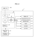
Fig. 2 is a block diagram of the overall configuration of the printer. -
Figs. 3A to 3C are views for illustrating a non-winding mode. -
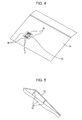
Fig. 4 is a perspective view of a downstream side supporting member. -
Fig. 5 is a view of the downstream side supporting member shown inFig. 4 and the peripheral members thereof when observed from the side. -
Fig. 6 is a schematic diagram showing a change in a sensing area. -
Fig. 7 is a schematic diagram showing an emissivity of a roll-shaped medium. - At least the following will be made clear by the description of the specification and the accompanying drawings.
- According to an aspect of the invention, there is provided a liquid discharging apparatus which includes a head which discharges a liquid onto a medium; a medium supporting portion which supports the medium; a heater which heats the medium supported by the medium supporting portion; a detecting unit which performs sensing and detects energy; and which controls radiation energy of the heater on the basis of the energy detected by the detecting unit, in which the medium supporting portion is provided with a sensing target portion which is sensed by the detecting unit, and in which an emissivity of the sensing target portion is from 0.7 to 1.
- According to the liquid discharging apparatus, it is possible to perform control of the heater appropriately.
- In addition, it is preferable that the detecting unit sense the sensing target portion or the medium supported by the medium supporting portion.
- In this case, even when a state is adopted in which the sensing target portion is sensed, it is possible to produce a situation in which radiation energy control is executed in the same manner as when a state is adopted in which the medium supported by the medium supporting portion is sensed, and it is possible to realize appropriate heater control.
- In addition, it is preferable that a difference between the emissivity of the sensing target portion and the emissivity of the medium be 0.1 or less.
- In this case, it is possible to perform control of the heater appropriately.
- In addition, it is preferable that the sensing target portion be formed from anodized aluminum.
- In this case, it is possible to realize the heater control appropriately using a simple method while benefitting from the merit of using a high-strength material such as metal as the medium supporting portion.
- In addition, it is preferable that a heat capacity of the medium which is in a heating range of the heater and the heat capacity of the sensing target portion be substantially equal.
- In this case, it is possible to perform control of the heater appropriately.
- In addition, it is preferable that the medium supporting portion be provided with a non-sensing target portion which is not sensed by the detecting unit, and that a gap be provided between the sensing target portion and the non-sensing target portion.
- In this case, it is possible to realize the heater control appropriately using a simple method.
- In addition, it is preferable that the medium supporting portion be a thin plate, and that the liquid discharging apparatus further include a supporting portion which supports the thin plate in a state in which a gap is provided between the thin plate and the supporting portion.
- In this case, it is possible to realize the heater control appropriately using a simple method while realizing a configuration in which the medium supporting portion is firmly supported.
- In addition, it is preferable that a size of a sensing area which the detecting unit senses be variable, and that the size of the sensing area change between when the detecting unit senses the sensing target portion and when the detecting unit senses the medium supported by the medium supporting portion.
- In this case, since it is possible to appropriately exhibit the capability of the detecting unit, it is possible to realize the heater control more appropriately.
-
-
Fig. 1 is a schematic diagram showing a configuration example of an ink jet printer (hereinafter simply referred to as the printer 1) as an example of the liquid discharging apparatus. -
Fig. 2 is a block diagram of the overall configuration of theprinter 1. - As shown in
Figs. 1 and2 , theprinter 1 according to the embodiment includes afeed unit 10, atransporting unit 20, awinding unit 25, ahead 30, a roll-shapedmedium supporting body 32, aheater 40, acutter 50, acontroller 60 and adetector group 70. - The
feed unit 10 feeds a roll-shaped medium 2, which is an example of the medium, to the transportingunit 20. As shown inFig. 1 , thefeed unit 10 includes a roll-shaped mediumwinding shaft 18, around which the roll-shaped medium 2 is wound to be rotatably supported, and arelay roller 19 for winding the roll-shaped medium 2 which is fed out from the roll-shaped mediumwinding shaft 18 and guiding the roll-shaped medium 2 to the transportingunit 20. - The transporting
unit 20 transports the roll-shaped medium 2 which is sent by thefeed unit 10 in a transport direction along a transport path which is set in advance. As shown inFig. 1 , thetransporting unit 20 includes afirst transport roller 23 and asecond transport roller 24 which is positioned on the downstream side in the transport direction in relation to thefirst transport roller 23. Thefirst transport roller 23 includes afirst drive roller 23a which is driven by a motor (not shown), and a first drivenroller 23b which is disposed so as to face thefirst drive roller 23a and interpose the roll-shaped medium 2 therebetween. Similarly, thesecond transport roller 24 includes asecond drive roller 24a which is driven by a motor (not shown), and a second drivenroller 24b which is disposed so as to face thesecond drive roller 24a and interpose the roll-shaped medium 2 therebetween. - The
winding unit 25 is for winding the roll-shaped medium 2 (the image recorded roll-shaped medium 2) which is sent by thetransporting unit 20. As shown inFig. 1 , thewinding unit 25 includes arelay roller 26 for winding the roll-shaped medium 2, which is sent from thesecond transport roller 24, from the upstream side in the transport direction and transporting the roll-shaped medium 2 to the downstream side in the transport direction, and a roll-shaped mediumwinding drive shaft 27 which is rotatably supported and which winds the roll-shaped medium 2 which is sent from therelay roller 26. - The
head 30 is for recording (printing) an image onto a part of the roll-shaped medium 2 which is positioned in the image recording region on the transport path. In other words, as shown inFig. 1 , thehead 30 forms an image by discharging an ink, which is an example of the liquid, from an ink discharge nozzle onto the roll-shaped medium 2 which is sent over a platen 33 (described below) by the transportingunit 20. - Furthermore, a piezo element (not shown) is provided in the ink discharge nozzle as the drive element for discharging ink droplets. When a voltage of a predetermined duration is applied across electrodes provided at both ends of the piezo element, the piezo element stretches according to the application time of the voltage and causes the side walls of the ink flow path to deform. Accordingly, the volume of the ink flow path contracts according to the expansion and contraction of the piezo element, and the ink which is equivalent to the amount of contraction becomes an ink droplet and is discharged from the ink discharge nozzle.
- The roll-shaped
medium supporting body 32 is for supporting the roll-shapedmedium 2 from below. The roll-shapedmedium supporting body 32 is made from metal (more specifically, is made from aluminum). In the embodiment, as shown inFig. 1 , theplaten 33 which opposes thehead 30, an upstreamside supporting member 34 which is positioned on the upstream side in the transport direction of theplaten 33, and a downstream side supporting member 35 (equivalent to the medium supporting portion) which is positioned on the downstream side in the transport direction of theplaten 33 are provided as the roll-shapedmedium supporting body 32. - The
heater 40 is for curing the ink by heating the roll-shaped medium 2 (in other words, the ink on the roll-shaped medium 2). Theheater 40 is an infrared heater which radiates infrared rays, and as shown inFig. 1 , is provided in a position which opposes the downstreamside supporting member 35. In other words, theheater 40 heats the roll-shapedmedium 2 which is supported by the downstreamside supporting member 35. - The
cutter 50 is for cutting the roll-shapedmedium 2. When the non-winding mode (described below) is executed, thecutter 50 cuts the image recorded roll-shapedmedium 2 off from the non-image recorded roll-shapedmedium 2 by cutting the roll-shapedmedium 2. As shown inFig. 1 , thecutter 50 is provided between thehead 30 and theheater 40 in the transport direction. - In addition, as shown in
Fig. 2 , theprinter 1 is provided with thecontroller 60 which manages the operation of theprinter 1 by controlling the units and the like described above, and thedetector group 70. After receiving a print command (print data) from acomputer 100 which is an external apparatus, theprinter 1 controls each of the units (thefeed unit 10, the transportingunit 20, the windingunit 25, thehead 30, theheater 40 and the cutter 50) using thecontroller 60. Thecontroller 60 prints an image onto the roll-shapedmedium 2 by controlling each unit on the basis of the print data received from thecomputer 100. The situation within theprinter 1 is monitored by thedetector group 70, and thedetector group 70 outputs the detection result to thecontroller 60. Thecontroller 60 controls each unit on the basis of the detection results output from thedetector group 70. - Furthermore, as shown in
Figs. 1 and2 , in theprinter 1 according to the embodiment, aninfrared sensor 72, which is a detecting unit, is provided as one of the detectors in thedetector group 70. Theinfrared sensor 72 detects energy of infrared rays by sensing the surface of the roll-shapedmedium 2 within the heating range (in other words, the radiation range, refer toFig. 1 ) of theheater 40. Furthermore, the radiation energy of theheater 40 is controlled by thecontroller 60 on the basis of the energy detected by theinfrared sensor 72. - The
controller 60 is a control unit for performing control of theprinter 1. Thecontroller 60 includes aninterface unit 61, aCPU 62,memory 63 and aunit control unit 64. Theinterface unit 61 performs transceiving of data between thecomputer 100, which is an external apparatus, and theprinter 1. TheCPU 62 is a processing unit for performing overall control of theprinter 1. Thememory 63 is for securing a region for storing programs of theCPU 62 or a working region, and includes a memory element such as RAM, which is volatile memory, or EEPROM, which is nonvolatile memory. TheCPU 62 controls each unit via theunit control unit 64 in accordance with the program stored in thememory 63. - Next, description will be given of the winding mode and the non-winding mode, which are the execution modes of the
printer 1 according to the embodiment, usingFigs. 1 and3A to 3C. Figs. 3A to 3C are views for illustrating a non-winding mode. Furthermore, since the state in which the winding mode is executed is represented inFig. 1 , the winding mode will be described with reference toFig. 1 . - As execution modes, the
printer 1 according to the embodiment is provided with a non-winding mode in which the windingunit 25 is not used and the image recorded roll-shapedmedium 2 is not wound by the roll-shaped medium windingdrive shaft 27, and a winding mode in which the windingunit 25 is used and the image recorded roll-shapedmedium 2 is wound by the roll-shaped medium windingdrive shaft 27. In other words, thecontroller 60 is configured to execute a winding mode in which the windingunit 25 is caused to wind the roll-shapedmedium 2 which is transported by the transportingunit 20, and a non-winding mode in which the windingunit 25 is not caused to wind the roll-shapedmedium 2 which is transported by the transportingunit 20. - As shown in
Fig. 1 , when the winding mode is executed, the roll-shapedmedium 2 is transported by the transportingunit 20 while maintaining a state of being wound around both thefeed unit 10 and the winding unit 25 (the roll-shapedmedium winding shaft 18 and the roll-shaped medium winding drive shaft 27). - Furthermore, a part of the roll-shaped
medium 2 that is fed out from the roll-shapedmedium winding shaft 18 reaches a position which opposes thehead 30 and an image is formed on the part at the position. When the roll-shapedmedium 2 is further transported, the part on which the image is formed eventually reaches a position which opposes theheater 40, and the part is irradiated with infrared rays at the position. Furthermore, according to further transport of the roll-shapedmedium 2, the part reaches the windingunit 25 and is wound onto the roll-shaped medium windingdrive shaft 27. - Meanwhile, as shown in
Figs. 3A to 3C , when the non-winding mode is executed, the roll-shapedmedium 2 is transported by the transportingunit 20 while maintaining a state of being wound around only thefeed unit 10. - Furthermore, a part of the roll-shaped
medium 2 that is fed out from the roll-shapedmedium winding shaft 18 reaches the position which opposes thehead 30 and an image (an example of the image formed range - the range in which the image is formed - in the roll-shapedmedium 2 is shown inFigs. 3A to 3C with the symbol W) is formed (Fig. 3A shows a state in which the image formation is complete) on the part at the position. - The image formed range W reaches the position which opposes the
heater 40 due to further transport of the roll-shapedmedium 2, and the image formed range W is irradiated with infrared rays at that position (a state in which the radiation of infrared rays onto the image formed range W is complete is shown inFig. 3B ). - Next, the roll-shaped
medium 2 is transported in a backward direction (back fed) by the transportingunit 20. Then, the image formed range W is returned to in front of thecutter 50 and the roll-shapedmedium 2 is cut by the cutter 50 (refer toFig. 3C ). Furthermore, accordingly, the image recorded roll-shapedmedium 2 is cut off from the non-image recorded roll-shapedmedium 2, and moves (is discharged) in the direction of the long white arrow while sliding on the downstreamside supporting member 35. - As described above, in the embodiment, the
printer 1 is provided with thecutter 50, and is capable not only of executing the normal winding mode, but also the non-winding mode. - Here, as shown in
Figs. 3A to 3C , when the non-winding mode is executed, there is a case in which the roll-shapedmedium 2 is positioned on the downstream side supporting member 35 (for example, the state ofFig. 3B ), and a case in which the roll-shapedmedium 2 is not positioned on the downstream side supporting member 35 (for example, the state ofFig. 3A ). Furthermore, accordingly, the problem described below may occur. - Furthermore, in the embodiment, the downstream
side supporting member 35 is subjected to countermeasures (contrivances) for solving (in other words, suppressing) the problem. - Firstly, description will be given bellow of the problem. Furthermore, continuing from the description of the problem, description will be given of the contrivances which the downstream
side supporting member 35 is subjected to usingFigs. 4 and 5. Fig. 4 is a perspective view of a downstreamside supporting member 35.Fig. 5 is a view of the downstreamside supporting member 35 shown inFig. 4 and the peripheral members thereof when observed from the side. Furthermore, the state of the downstreamside supporting member 35 when observed from the side is also represented inFig. 1 . However, the downstreamside supporting member 35 ofFig. 1 is a view of the downstreamside supporting member 35 ofFig. 5 re-written schematically. - As described above, when the non-winding mode is executed, the roll-shaped
medium 2 is sometimes positioned on the downstreamside supporting member 35 and sometimes is not. - When the roll-shaped
medium 2 is positioned on the downstreamside supporting member 35, theinfrared sensor 72 senses the surface of the roll-shapedmedium 2 within the heating range of theheater 40. Furthermore, thecontroller 60 controls the radiation energy of theheater 40 on the basis of the energy of the infrared rays detected by theinfrared sensor 72. Furthermore, accordingly, the roll-shapedmedium 2 is to be set to a predetermined temperature (approximately 100°C in the embodiment). - However, when a state is entered in which the roll-shaped
medium 2 is not positioned on the downstreamside supporting member 35, the roll-shapedmedium 2 is not present at the sensing destination. In this case, theinfrared sensor 72 senses the downstream side supporting member 35 (the portion of the downstreamside supporting member 35 which is sensed is referred to as a sensing target portion 36). In other words, thesensing target portion 36 provided on the downstreamside supporting member 35 is sensed by theinfrared sensor 72, and the control of the radiation energy is performed on the basis of the sensing results. In other words, there is a case in which the detecting unit senses the sensing target portion provided on the medium supporting portion, and there is a case in which the detecting unit senses the medium supported by the medium supporting portion. - Furthermore, in this state (a state referred to as a second state, in which the roll-shaped
medium 2 is not present at the sensing destination), since the situation at the sensing destination is different (for example, the difference between paper and metal) from that when the surface of the roll-shapedmedium 2 is sensed, radiation energy control (such as when the surface of the roll-shapedmedium 2 is sensed) may not be performed in the same manner as when the roll-shapedmedium 2 is at the sensing destination (referred to as a first state). Therefore, when the roll-shapedmedium 2 has entered a state of being positioned on the downstreamside supporting member 35 from the second state (in other words, when the roll-shapedmedium 2 reaches the downstream side supporting member 35), a problem occurs in that the radiation energy is not the (appropriate) radiation energy for setting the roll-shapedmedium 2 to the predetermined temperature. - Therefore, it is desirable that radiation energy control be performed in the same manner as when the roll-shaped
medium 2 is present at the sensing destination, even when the roll-shapedmedium 2 is not present at the sensing destination. In this configuration, when the roll-shapedmedium 2 has entered a state of being positioned on the downstreamside supporting member 35 from the second state (in other words, when the roll-shapedmedium 2 reaches the downstream side supporting member 35), the radiation energy is already the (appropriate) radiation energy for setting the roll-shapedmedium 2 to the predetermined temperature, and the problem is solved. - In the embodiment, since the radiation energy control is executed in the same manner as when the roll-shaped
medium 2 is present at the sensing destination, even when the roll-shapedmedium 2 is not present at the sensing destination, as the contrivance, the characteristics of thesensing target portion 36 which is sensed by theinfrared sensor 72 in a state in which the roll-shapedmedium 2 is not present at the sensing destination are matched with the characteristics of the roll-shapedmedium 2. - First, the heat capacity of the
sensing target portion 36 is matched with the heat capacity of the roll-shapedmedium 2. More specifically, the volume (the volume of the portion shaded with diagonal lines inFig. 4 ) of thesensing target portion 36 is set such that the heat capacity of the roll-shapedmedium 2 which is in the heating range (refer toFig. 1 ) of the heater and the heat capacity of the sensing target portion 36 (the portion shaded with diagonal lines inFig. 4 ) are substantially equal. Since the heat capacity per unit volume of thesensing target portion 36, which is made from metal, is higher than that of the roll-shapedmedium 2, as described below, a countermeasure is performed so as to reduce the volume of thesensing target portion 36, which is made from metal, as much as possible. - Furthermore, in the embodiment, in order to realize the reduction in volume, the configuration of the downstream
side supporting member 35 is subjected to the contrivance which is described below. - In other words, as shown in
Fig. 4 , a gap G is provided between thesensing target portion 36 and a non-sensing target portion 38 (which is not sensed) which is positioned in the periphery of thesensing target portion 36. In other words, in order to narrow thesensing target portion 36, thesensing target portion 36 is treated as a small island-shape, and is isolated from thenon-sensing target portion 38. - Furthermore, as shown in
Fig. 5 , in order to reduce the thickness of thesensing target portion 36, the downstreamside supporting member 35 which is provided with thesensing target portion 36 is configured from a thin plate (in the embodiment, a thin plate of a 0.5 mm thickness), and a supportingportion 52 is provided which supports the thin plate in a state in which a gap is provided between the thin plate and the supporting portion. In other words, by suspending the downstreamside supporting member 35, which is a thin plate, from the supportingportion 52, the thickness of thesensing target portion 36 is reduced while realizing a configuration in which the downstreamside supporting member 35 is firmly supported. - In addition, secondly, the emissivity of the
sensing target portion 36 is matched with the emissivity of the roll-shapedmedium 2. As shown inFig. 7 , when the emissivity of the main medium used as the roll-shapedmedium 2 was measured using an emissivity measuring instrument, the emissivity of the medium was in the range of approximately 0.8 to approximately 0.95. Therefore, the emissivity of the sensing target portion is set to from 0.7 to 1. By using these values, the difference (the emissivity difference) between the emissivity of thesensing target portion 36 and the emissivity of the roll-shapedmedium 2 is 0.1 or less. When the emissivity difference is 0.1 or less, the emissivity difference is equivalent to approximately 3°C or less when converted into a temperature difference, which is considered to be a level which is not a problem for temperature control. Therefore, when the emissivity of thesensing target portion 36 is set to from 0.7 to 1, it is possible to appropriately perform control of theheater 40 in relation to a medium such as an acrylic resin, a PET resin, a vinyl chloride resin, fabric and paper, which are exemplified in the embodiment. In addition, when the emissivity of thesensing target portion 36 is set to from 0.85 to 0.95, it is possible to further reduce the emissivity difference in relation to a medium such as a PET resin, a vinyl chloride resin, fabric and paper, which are exemplified in the embodiment. Therefore, when the emissivity of thesensing target portion 36 is set to from 0.85 to 0.95, it is possible to more appropriately perform control of theheater 40 in relation to some types of media. In addition, when the emissivity of thesensing target portion 36 is set to 0.9, it is possible to further reduce the emissivity difference in relation to a vinyl chloride resin medium which is exemplified in the embodiment. Therefore, when the emissivity of thesensing target portion 36 is set to 0.9, it is possible to more appropriately perform control of theheater 40 in relation to some types of media. - At this time, since the emissivity of the
sensing target portion 36, which is made from aluminum (the emissivity of aluminum is approximately 0.1), is less than that of the roll-shapedmedium 2, as described below, a countermeasure is performed so as to increase the emissivity of thesensing target portion 36, which is made from metal. - In other words, in the embodiment, by anodizing the downstream
side supporting member 35, which is made from aluminum, the emissivity of thesensing target portion 36 which is provided on the downstreamside supporting member 35 rises greatly (rises from approximately 0.1 to approximately 0.9), and the difference (the emissivity difference) between the emissivity of the sensing target portion and the emissivity of the roll-shapedmedium 2 is 0.1 or less. - As described above, the
printer 1 according to the embodiment includes thehead 30 which discharges an ink onto the roll-shapedmedium 2, the downstreamside supporting member 35 which supports the roll-shapedmedium 2, theheater 40 which heats the roll-shapedmedium 2 supported by the downstreamside supporting member 35, and theinfrared sensor 72 which performs sensing and detects energy. In addition, theprinter 1 controls radiation energy of theheater 40 on the basis of the energy detected by theinfrared sensor 72. In addition, the downstreamside supporting member 35 is provided with thesensing target portion 36 which is sensed by theinfrared sensor 72. - In other words, the
printer 1 according to the embodiment includes thehead 30 which discharges the ink onto the roll-shapedmedium 2, the downstreamside supporting member 35 which supports the roll-shapedmedium 2, theheater 40 which cures the ink by heating the roll-shapedmedium 2 supported by the downstreamside supporting member 35, theinfrared sensor 72 which detects energy of infrared rays by sensing the surface of the roll-shapedmedium 2 within the heating range of theheater 40, and which senses thesensing target portion 36 provided on the downstreamside supporting member 35 when the roll-shapedmedium 2 is not present at the sensing destination, and thecontroller 60 which controls radiation energy of theheater 40 on the basis of the energy detected by theinfrared sensor 72. Furthermore, in theprinter 1, the emissivity of the sensing target portion is set to from 0.7 to 1. - Therefore, the radiation energy control is executed in the same manner as when the roll-shaped
medium 2 is present at the sensing destination, even when the roll-shapedmedium 2 is not present at the sensing destination, and it is possible to perform control of theheater 40 appropriately. - In addition, in the embodiment, the difference between the emissivity of the sensing target portion and the emissivity of the roll-shaped
medium 2 is set to 0.1 or less. - Therefore, the radiation energy control is executed in the same manner as when the roll-shaped
medium 2 is present at the sensing destination, even when the roll-shapedmedium 2 is not present at the sensing destination, and it is possible to perform control of theheater 40 appropriately. - In addition, in the embodiment, the
sensing target portion 36 is formed from anodized aluminum. - Therefore, it is possible to create a situation in which the radiation energy control is executed in the same manner as when the roll-shaped
medium 2 is present at the sensing destination, even when the roll-shapedmedium 2 is not present at the sensing destination using a simple method while benefitting from the merit of using a high-strength material such as metal as the downstreamside supporting member 35, and it is possible to realize the heater control appropriately. - In addition, in the embodiment, the heat capacity of the roll-shaped
medium 2 which is in the heating range (refer toFig. 1 ) of theheater 40 and the heat capacity of thesensing target portion 36 are substantially equal. - Therefore, the radiation energy control is executed in the same manner as when the roll-shaped
medium 2 is present at the sensing destination, even when the roll-shapedmedium 2 is not present at the sensing destination, and it is possible to perform control of theheater 40 appropriately. - In addition, in the embodiment, the downstream
side supporting member 35 is provided with thenon-sensing target portion 38 which is not sensed by theinfrared sensor 72, and the gap G is provided between thesensing target portion 36 and thenon-sensing target portion 38. - Therefore, it is possible to create a situation in which the radiation energy control is executed in the same manner as when the roll-shaped
medium 2 is present at the sensing destination, even when the roll-shapedmedium 2 is not present at the sensing destination using a simple method, and it is possible to realize the appropriate heater control. - In addition, in the embodiment, the downstream
side supporting member 35 is a thin plate, and theprinter 1 includes the supportingportion 52 which supports the thin plate in a state in which a gap is provided between the thin plate and the supportingportion 52. - Therefore, it is possible to create a situation in which the radiation energy control is executed in the same manner as when the roll-shaped
medium 2 is present at the sensing destination, even when the roll-shapedmedium 2 is not present at the sensing destination using a simple method, while realizing a configuration in which the downstreamside supporting member 35 is firmly supported, and it is possible to realize the appropriate heater control. - The embodiments described above are intended to facilitate understanding of the invention and should not be interpreted as limiting the invention. It is needless to say that the invention may be modified and improved within a range not exceeding the scope of the invention as defined by the claims. In particular, the embodiments described hereinafter are included in the invention.
- In the embodiment, the liquid discharging apparatus (the liquid ejecting apparatus) is embodied by an ink jet printer. However, a liquid ejecting apparatus that ejects, discharges or the like a liquid other than ink may also be adopted, and it is possible to use such an apparatus in various types of liquid ejecting apparatus provided with a liquid ejecting head or the like which discharges minute droplets. Furthermore, the term "droplets" refers to the state of the liquid discharged from the liquid ejecting apparatus, and includes liquids of a droplet shape, a tear shape and a liquid which forms a line-shaped tail. In addition, the term "liquid" referred to herein may be a material which can be ejected from the liquid ejecting apparatus. For example, the liquid may be a material which is in a liquid phase state, and includes liquid bodies of high or low viscosity, and fluid bodies such as sol, aqueous gel, other inorganic solvents, organic solvents, solutions, liquid resin, and liquid metal (molten metal). In addition, the liquid not only includes liquids as a state of a material, but also includes solutions, disperses and mixtures in which particles of functional material formed from solids such as pigments and metal particulate are dissolved, dispersed or mixed into a solvent. In addition, representative examples of the liquid include the ink described in the embodiment or liquid crystal. Here, the term "ink" includes general aqueous inks and solvent inks, in addition to various liquid compositions such as gel ink and hot melt ink. A specific example of the liquid ejecting apparatus is a liquid ejecting apparatus which ejects a liquid which contains a material such as an electrode material or a color material in the form of a dispersion or a solution. The electrode material, the color material or the like may be used in the manufacture and the like of liquid crystal displays, EL (electro-luminescence) displays, surface emission displays and color filters. In addition, the liquid ejecting apparatus may also be a liquid ejecting apparatus which ejects biological organic matter used in the manufacture of bio-chips, a liquid ejecting apparatus which is used as a precision pipette to eject a liquid to be a sample, a textile printing apparatus, a micro dispenser or the like. Furthermore, a liquid ejecting apparatus which ejects lubricant at pinpoint precision into precision machines such as clocks and cameras, a liquid ejecting apparatus which ejects a transparent resin liquid such as ultraviolet curing resin onto a substrate in order to form minute semispherical lenses (optical lenses) and the like used in optical communication devices and the like, or a liquid ejecting apparatus which ejects etching liquid such as an acid or an alkaline for etching a substrate or the like, may also be adopted as the liquid ejecting apparatus. Furthermore, it is possible to apply the invention to any one type of the liquid ejecting apparatuses described above.
- In addition, the ink of the embodiment may contain resin emulsion. When the recording medium is heated, preferably, the resin emulsion exhibits the effect of sufficiently fixing a colorant ink onto the recording medium and of obtaining favorable image fastness properties by forming a resin film with wax (emulsion). According to the effects described above, the recorded object which is recorded using a colorant ink containing resin emulsion, has particularly excellent image fastness properties on a recording medium which is non-absorbent or has low absorbency in relation to ink. Examples of the resin emulsion are not limited hereto, but include monomers or polymers of (meth)acrylate, (meth)acrylate ester, acrylonitrile, cyanoacrylate, acrylamide, olefin, styrene, vinyl acetate, vinyl chloride, vinyl alcohol, vinyl ether, vinylpyrrolidone, vinyl pyridine, vinylcarbazole, vinyl imidazole and vinylidene chloride, in addition to fluororesin and natural resin. Of these, at least one of (meth)acrylic-based resin and styrene-(meth)acrylate copolymer-based resin is preferable, at least one of acrylic-based resin and styrene-acrylate copolymer-based resin is more preferable, and styrene-acrylate copolymer-based resin is still more preferable. Furthermore, the copolymers described above may be embodied by any of a random copolymer, a block copolymer, an alternating copolymer and a graft copolymer.
- In addition, in the embodiment, the transporting
unit 20 includes thefirst transport roller 23 which is positioned closer to the upstream side in the transport direction than thehead 30, and thesecond transport roller 24 which is positioned closer to the downstream side in the transport direction than thehead 30. However, the number and disposition of transport rollers are not limited thereto. - In addition, in the embodiment, an example was given in which the roll-shaped
medium 2 is used as an example of the medium. However, the medium may also be a cut-sheet medium. When the medium is a cut-sheet medium, the likelihood is high that the medium is in a state of not being positioned on the downstreamside supporting member 35 when the printing is started. However, it is desirable that the radiation energy of theheater 40 already be an (appropriate) radiation energy for setting the medium to a predetermined temperature, even when the printing is started. If the invention is used, it is possible to perform control of theheater 40 appropriately even when the medium is a cut-sheet medium. - In addition, in the embodiment, an example is given in which the
infrared sensor 72 is used as the detecting unit. However, other sensors may also be used for the detecting unit. When the detecting unit is a sensor that detects electromagnetic waves which are radiated from the surface of the medium, the detecting unit may be a sensor that detects ultraviolet rays, microwaves and the like. Of the sensors, in order to estimate the temperature of a medium, it is more effective to use the infrared sensor. Furthermore, the term "infrared rays" refers to electromagnetic waves in a wavelength region of approximately 0.7 µm to 1000 µm. Theinfrared sensor 72 may detect electromagnetic waves in a wavelength region of at least a portion of the wavelength region of approximately 0.7 µm to 1000 µm. - In addition, the size of the sensing area which the detecting unit senses is variable, and the size of the sensing area may change between a first state in which the roll-shaped
medium 2 is present at the sensing destination, and a second state in which the roll-shapedmedium 2 is not present at the sensing destination. In other words, the size of the sensing area changes between a case in which the detecting unit senses the sensing target portion and a case in which the detecting unit senses the medium supported by the medium supporting portion. - In other words, as the detecting unit, a sensor is prepared which can change the size of the sensing area, and as shown in
Fig. 6 , thecontroller 60 controls (reduces) the size of the sensing area such that the sensing area fits within thesensing target portion 36 in the second state in which thesensing target portion 36 is sensed. Meanwhile, in the first state in which the surface of the roll-shapedmedium 2 is sensed, since it is not necessary to fit the sensing area within thesensing target portion 36, the size of the sensing area is increased (preferably, is set to the maximum size) in relation to the size in the second state in order to increase the uniformity of the sensing results by causing the detecting unit to sense a wide range. - Furthermore, by adopting such a configuration, since it is possible to appropriately exhibit the capability of the sensor which is used as the detecting unit, it is possible to realize the more appropriate heater control.
Claims (12)
- A liquid discharging apparatus (1) comprising:a head (30) for discharging a liquid onto a medium (2);a heater (40) for heating the medium;a detecting unit (12) for performing sensing and detecting energy;a sensing target portion (36) which is arranged to be sensed by the detecting unit and has an emissivity from 0.7 to 1; anda control unit (64) for controlling radiation energy of the heater on the basis of the energy detected by the detecting unit.
- The liquid discharging apparatus according to Claim 1,
wherein the sensing target portion is disposed within a heating range of the heater. - The liquid discharging apparatus according to Claim 1 to claim 2,
wherein the detecting unit is adapted to sense the sensing target portion or the medium. - The liquid discharging apparatus according to Claim 3,
wherein the detecting unit is adapted to sense the medium supported by the medium supporting portion. - The liquid discharging apparatus according to any one of the preceding claims,
wherein a difference between the emissivity of the sensing target portion and the emissivity of the medium is 0.1 or less. - The liquid discharging apparatus according to any one of the preceding claims,
wherein the sensing target portion is formed from anodized aluminum. - The liquid discharging apparatus according to any one of the preceding claims,
wherein a heat capacity of the medium which is in a heating range of the heater and the heat capacity of the sensing target portion are substantially equal. - The liquid discharging apparatus according to any one of the preceding claims, further comprising a medium supporting portion (52) which supports the medium.
- The liquid discharging apparatus according to Claim 8,
wherein the medium supporting portion is provided with the sensing target portion. - The liquid discharging apparatus according to Claim 8 or Claim 9,
wherein the medium supporting portion includes a non-sensing target portion (38) which is arranged not to be sensed by the detecting unit, and
wherein a gap (G) is provided between the sensing target portion and the non-sensing target portion. - The liquid discharging apparatus according to any one of Claims 8 to 10,
wherein the medium supporting portion is provided with a thin plate (35) which supports the medium and a supporting portion (52) which supports the thin plate in a state in which a gap is provided between the thin plate and the supporting portion. - The liquid discharging apparatus according to any one of the preceding claims,
wherein a size of a sensing area which the detecting unit senses is variable, and
wherein the size of the sensing area changes between when the detecting unit is arranged to sense the sensing target portion (36) and when the detecting unit is arranged to sense the medium.
Applications Claiming Priority (1)
| Application Number | Priority Date | Filing Date | Title |
|---|---|---|---|
| JP2013004304A JP6135138B2 (en) | 2013-01-15 | 2013-01-15 | Liquid ejection device |
Publications (2)
| Publication Number | Publication Date |
|---|---|
| EP2754561A1 true EP2754561A1 (en) | 2014-07-16 |
| EP2754561B1 EP2754561B1 (en) | 2015-11-04 |
Family
ID=49999732
Family Applications (1)
| Application Number | Title | Priority Date | Filing Date |
|---|---|---|---|
| EP14151091.7A Not-in-force EP2754561B1 (en) | 2013-01-15 | 2014-01-14 | Liquid discharging apparatus |
Country Status (4)
| Country | Link |
|---|---|
| US (2) | US9174460B2 (en) |
| EP (1) | EP2754561B1 (en) |
| JP (1) | JP6135138B2 (en) |
| CN (1) | CN103921552B (en) |
Families Citing this family (5)
| Publication number | Priority date | Publication date | Assignee | Title |
|---|---|---|---|---|
| JP6720576B2 (en) * | 2016-03-01 | 2020-07-08 | セイコーエプソン株式会社 | Printer |
| US10300712B2 (en) | 2016-07-08 | 2019-05-28 | Ricoh Company, Ltd. | Drying device and printing apparatus |
| CN106739451B (en) * | 2016-12-09 | 2022-11-29 | 深圳弘美数码纺织技术有限公司 | Spray drawing printer |
| US20180264865A1 (en) * | 2017-03-14 | 2018-09-20 | Casio Computer Co., Ltd. | Image formation system, three-dimensional image formation system, three-dimensional image formation method, and computer-readable storage medium |
| JP7293675B2 (en) * | 2019-01-31 | 2023-06-20 | セイコーエプソン株式会社 | Drying device and liquid ejection device |
Citations (4)
| Publication number | Priority date | Publication date | Assignee | Title |
|---|---|---|---|---|
| JP2003207965A (en) * | 2002-01-16 | 2003-07-25 | Seiko Epson Corp | Image forming device |
| US20090237478A1 (en) * | 2008-03-24 | 2009-09-24 | Seiko Epson Corporation | Recording apparatus and method of adjusting temperature of transport belt of recording apparatus |
| JP2009251408A (en) | 2008-04-09 | 2009-10-29 | Murata Mach Ltd | Image forming apparatus |
| JP2012121192A (en) * | 2010-12-07 | 2012-06-28 | Fujifilm Corp | Image forming apparatus |
Family Cites Families (19)
| Publication number | Priority date | Publication date | Assignee | Title |
|---|---|---|---|---|
| JPH0967764A (en) * | 1992-11-24 | 1997-03-11 | Satake:Kk | Fiber that emits fluorescent light |
| JP2000096349A (en) * | 1998-09-22 | 2000-04-04 | Kanebo Ltd | Luminous colored fiber and luminous colored product using the same |
| EP1070597B1 (en) * | 1999-02-04 | 2005-12-28 | Matsushita Electric Industrial Co., Ltd. | Object-to-be-printed detector and print detecting method |
| JP2001214333A (en) * | 2000-02-02 | 2001-08-07 | Kuraray Co Ltd | Polychromatic phosphorescent fiber |
| JP2002285440A (en) * | 2001-03-26 | 2002-10-03 | Daiju:Kk | Luminous yarn or fluorescent yarn and fiber product using the same |
| US20040174426A1 (en) * | 2001-12-25 | 2004-09-09 | Seiko Epson Corporation | Image forming apparatus |
| JP4680526B2 (en) * | 2003-04-08 | 2011-05-11 | オセ−テクノロジーズ ビーブイ | printer |
| JP4429923B2 (en) * | 2003-04-18 | 2010-03-10 | 株式会社ミマキエンジニアリング | Inkjet printer |
| US7399048B2 (en) * | 2003-09-10 | 2008-07-15 | Fujifilm Corporation | Inkjet recording apparatus and method for detecting discharge defects |
| JP4129273B2 (en) * | 2003-10-17 | 2008-08-06 | 松下電器産業株式会社 | Fixing apparatus and temperature control method |
| JP2007068614A (en) * | 2005-09-05 | 2007-03-22 | Hasegawa Seisakusho:Kk | Amulet |
| JP2007068613A (en) * | 2005-09-05 | 2007-03-22 | Hasegawa Seisakusho:Kk | Amulet bag |
| JP4890960B2 (en) * | 2006-06-19 | 2012-03-07 | キヤノン株式会社 | Recording device |
| JP4956767B2 (en) * | 2009-04-27 | 2012-06-20 | 福井県 | Decorative lighting mechanism using moiré pattern |
| JP5238679B2 (en) | 2009-12-15 | 2013-07-17 | 株式会社東芝 | Air conditioning control device, air conditioning control method, and radiation temperature measuring device |
| JP5448973B2 (en) * | 2010-03-30 | 2014-03-19 | 富士フイルム株式会社 | Image forming apparatus |
| JP5673082B2 (en) | 2010-12-24 | 2015-02-18 | セイコーエプソン株式会社 | Recording device |
| JP5664226B2 (en) * | 2010-12-28 | 2015-02-04 | セイコーエプソン株式会社 | Recording device |
| JP5899955B2 (en) * | 2012-01-20 | 2016-04-06 | セイコーエプソン株式会社 | RECORDING MEDIUM CONVEYING DEVICE AND RECORDING DEVICE |
-
2013
- 2013-01-15 JP JP2013004304A patent/JP6135138B2/en not_active Expired - Fee Related
-
2014
- 2014-01-08 US US14/150,415 patent/US9174460B2/en not_active Expired - Fee Related
- 2014-01-14 EP EP14151091.7A patent/EP2754561B1/en not_active Not-in-force
- 2014-01-15 CN CN201410018227.9A patent/CN103921552B/en not_active Expired - Fee Related
-
2015
- 2015-10-06 US US14/875,792 patent/US9724939B2/en not_active Expired - Fee Related
Patent Citations (4)
| Publication number | Priority date | Publication date | Assignee | Title |
|---|---|---|---|---|
| JP2003207965A (en) * | 2002-01-16 | 2003-07-25 | Seiko Epson Corp | Image forming device |
| US20090237478A1 (en) * | 2008-03-24 | 2009-09-24 | Seiko Epson Corporation | Recording apparatus and method of adjusting temperature of transport belt of recording apparatus |
| JP2009251408A (en) | 2008-04-09 | 2009-10-29 | Murata Mach Ltd | Image forming apparatus |
| JP2012121192A (en) * | 2010-12-07 | 2012-06-28 | Fujifilm Corp | Image forming apparatus |
Also Published As
| Publication number | Publication date |
|---|---|
| JP2014136315A (en) | 2014-07-28 |
| US20140198147A1 (en) | 2014-07-17 |
| US9174460B2 (en) | 2015-11-03 |
| US20160023477A1 (en) | 2016-01-28 |
| CN103921552A (en) | 2014-07-16 |
| JP6135138B2 (en) | 2017-05-31 |
| EP2754561B1 (en) | 2015-11-04 |
| CN103921552B (en) | 2017-05-03 |
| US9724939B2 (en) | 2017-08-08 |
Similar Documents
| Publication | Publication Date | Title |
|---|---|---|
| US9724939B2 (en) | Liquid discharging apparatus | |
| US9527312B2 (en) | Liquid discharging apparatus | |
| US8955956B2 (en) | Printing apparatus and inkjet method | |
| JP6708821B2 (en) | Image forming apparatus, image forming program, and image forming method | |
| JP5929049B2 (en) | Recording device | |
| EP2423136A2 (en) | Transport device, recording apparatus, transport method | |
| JP7379707B2 (en) | printing device | |
| EP2287009B1 (en) | Erase decoupled from writing for erasable paper | |
| US9475285B2 (en) | Liquid ejecting apparatus | |
| CN103707641B (en) | Liquid injection apparatus | |
| US9623675B2 (en) | Liquid discharging apparatus and heating unit control method | |
| EP2423141B1 (en) | Transport device, recording apparatus, transport method | |
| US9821570B2 (en) | Medium heating device | |
| JP5899955B2 (en) | RECORDING MEDIUM CONVEYING DEVICE AND RECORDING DEVICE | |
| JP2013043434A (en) | Recording apparatus | |
| JP2015174227A (en) | Liquid ejection device and heating unit control method | |
| EP2754630B1 (en) | Medium transport device | |
| JP2015168087A (en) | Liquid discharge device and heating section control method | |
| US20150251465A1 (en) | Image recording apparatus and sheet transfer method | |
| JP5585179B2 (en) | Medium discharging apparatus and recording apparatus | |
| JP2012218365A (en) | Inkjet recording apparatus and inkjet recording method | |
| JP6492729B2 (en) | Image forming apparatus and image forming program | |
| JP2016137606A (en) | Liquid injection device |
Legal Events
| Date | Code | Title | Description |
|---|---|---|---|
| PUAI | Public reference made under article 153(3) epc to a published international application that has entered the european phase |
Free format text: ORIGINAL CODE: 0009012 |
|
| 17P | Request for examination filed |
Effective date: 20140114 |
|
| AK | Designated contracting states |
Kind code of ref document: A1 Designated state(s): AL AT BE BG CH CY CZ DE DK EE ES FI FR GB GR HR HU IE IS IT LI LT LU LV MC MK MT NL NO PL PT RO RS SE SI SK SM TR |
|
| AX | Request for extension of the european patent |
Extension state: BA ME |
|
| R17P | Request for examination filed (corrected) |
Effective date: 20141217 |
|
| RBV | Designated contracting states (corrected) |
Designated state(s): AL AT BE BG CH CY CZ DE DK EE ES FI FR GB GR HR HU IE IS IT LI LT LU LV MC MK MT NL NO PL PT RO RS SE SI SK SM TR |
|
| GRAP | Despatch of communication of intention to grant a patent |
Free format text: ORIGINAL CODE: EPIDOSNIGR1 |
|
| INTG | Intention to grant announced |
Effective date: 20150526 |
|
| GRAS | Grant fee paid |
Free format text: ORIGINAL CODE: EPIDOSNIGR3 |
|
| GRAA | (expected) grant |
Free format text: ORIGINAL CODE: 0009210 |
|
| AK | Designated contracting states |
Kind code of ref document: B1 Designated state(s): AL AT BE BG CH CY CZ DE DK EE ES FI FR GB GR HR HU IE IS IT LI LT LU LV MC MK MT NL NO PL PT RO RS SE SI SK SM TR |
|
| REG | Reference to a national code |
Ref country code: GB Ref legal event code: FG4D |
|
| REG | Reference to a national code |
Ref country code: CH Ref legal event code: EP |
|
| REG | Reference to a national code |
Ref country code: AT Ref legal event code: REF Ref document number: 758908 Country of ref document: AT Kind code of ref document: T Effective date: 20151115 |
|
| REG | Reference to a national code |
Ref country code: IE Ref legal event code: FG4D |
|
| REG | Reference to a national code |
Ref country code: DE Ref legal event code: R096 Ref document number: 602014000398 Country of ref document: DE |
|
| REG | Reference to a national code |
Ref country code: FR Ref legal event code: PLFP Year of fee payment: 3 |
|
| REG | Reference to a national code |
Ref country code: NL Ref legal event code: MP Effective date: 20151104 |
|
| REG | Reference to a national code |
Ref country code: LT Ref legal event code: MG4D |
|
| REG | Reference to a national code |
Ref country code: AT Ref legal event code: MK05 Ref document number: 758908 Country of ref document: AT Kind code of ref document: T Effective date: 20151104 |
|
| PG25 | Lapsed in a contracting state [announced via postgrant information from national office to epo] |
Ref country code: IT Free format text: LAPSE BECAUSE OF FAILURE TO SUBMIT A TRANSLATION OF THE DESCRIPTION OR TO PAY THE FEE WITHIN THE PRESCRIBED TIME-LIMIT Effective date: 20151104 Ref country code: NL Free format text: LAPSE BECAUSE OF FAILURE TO SUBMIT A TRANSLATION OF THE DESCRIPTION OR TO PAY THE FEE WITHIN THE PRESCRIBED TIME-LIMIT Effective date: 20151104 Ref country code: HR Free format text: LAPSE BECAUSE OF FAILURE TO SUBMIT A TRANSLATION OF THE DESCRIPTION OR TO PAY THE FEE WITHIN THE PRESCRIBED TIME-LIMIT Effective date: 20151104 Ref country code: ES Free format text: LAPSE BECAUSE OF FAILURE TO SUBMIT A TRANSLATION OF THE DESCRIPTION OR TO PAY THE FEE WITHIN THE PRESCRIBED TIME-LIMIT Effective date: 20151104 Ref country code: NO Free format text: LAPSE BECAUSE OF FAILURE TO SUBMIT A TRANSLATION OF THE DESCRIPTION OR TO PAY THE FEE WITHIN THE PRESCRIBED TIME-LIMIT Effective date: 20160204 Ref country code: IS Free format text: LAPSE BECAUSE OF FAILURE TO SUBMIT A TRANSLATION OF THE DESCRIPTION OR TO PAY THE FEE WITHIN THE PRESCRIBED TIME-LIMIT Effective date: 20160304 Ref country code: LT Free format text: LAPSE BECAUSE OF FAILURE TO SUBMIT A TRANSLATION OF THE DESCRIPTION OR TO PAY THE FEE WITHIN THE PRESCRIBED TIME-LIMIT Effective date: 20151104 |
|
| PG25 | Lapsed in a contracting state [announced via postgrant information from national office to epo] |
Ref country code: RS Free format text: LAPSE BECAUSE OF FAILURE TO SUBMIT A TRANSLATION OF THE DESCRIPTION OR TO PAY THE FEE WITHIN THE PRESCRIBED TIME-LIMIT Effective date: 20151104 Ref country code: GR Free format text: LAPSE BECAUSE OF FAILURE TO SUBMIT A TRANSLATION OF THE DESCRIPTION OR TO PAY THE FEE WITHIN THE PRESCRIBED TIME-LIMIT Effective date: 20160205 Ref country code: LV Free format text: LAPSE BECAUSE OF FAILURE TO SUBMIT A TRANSLATION OF THE DESCRIPTION OR TO PAY THE FEE WITHIN THE PRESCRIBED TIME-LIMIT Effective date: 20151104 Ref country code: BE Free format text: LAPSE BECAUSE OF NON-PAYMENT OF DUE FEES Effective date: 20160131 Ref country code: PL Free format text: LAPSE BECAUSE OF FAILURE TO SUBMIT A TRANSLATION OF THE DESCRIPTION OR TO PAY THE FEE WITHIN THE PRESCRIBED TIME-LIMIT Effective date: 20151104 Ref country code: AT Free format text: LAPSE BECAUSE OF FAILURE TO SUBMIT A TRANSLATION OF THE DESCRIPTION OR TO PAY THE FEE WITHIN THE PRESCRIBED TIME-LIMIT Effective date: 20151104 Ref country code: FI Free format text: LAPSE BECAUSE OF FAILURE TO SUBMIT A TRANSLATION OF THE DESCRIPTION OR TO PAY THE FEE WITHIN THE PRESCRIBED TIME-LIMIT Effective date: 20151104 Ref country code: SE Free format text: LAPSE BECAUSE OF FAILURE TO SUBMIT A TRANSLATION OF THE DESCRIPTION OR TO PAY THE FEE WITHIN THE PRESCRIBED TIME-LIMIT Effective date: 20151104 Ref country code: PT Free format text: LAPSE BECAUSE OF FAILURE TO SUBMIT A TRANSLATION OF THE DESCRIPTION OR TO PAY THE FEE WITHIN THE PRESCRIBED TIME-LIMIT Effective date: 20160304 |
|
| PG25 | Lapsed in a contracting state [announced via postgrant information from national office to epo] |
Ref country code: CZ Free format text: LAPSE BECAUSE OF FAILURE TO SUBMIT A TRANSLATION OF THE DESCRIPTION OR TO PAY THE FEE WITHIN THE PRESCRIBED TIME-LIMIT Effective date: 20151104 |
|
| REG | Reference to a national code |
Ref country code: DE Ref legal event code: R097 Ref document number: 602014000398 Country of ref document: DE |
|
| PG25 | Lapsed in a contracting state [announced via postgrant information from national office to epo] |
Ref country code: RO Free format text: LAPSE BECAUSE OF FAILURE TO SUBMIT A TRANSLATION OF THE DESCRIPTION OR TO PAY THE FEE WITHIN THE PRESCRIBED TIME-LIMIT Effective date: 20151104 Ref country code: LU Free format text: LAPSE BECAUSE OF FAILURE TO SUBMIT A TRANSLATION OF THE DESCRIPTION OR TO PAY THE FEE WITHIN THE PRESCRIBED TIME-LIMIT Effective date: 20160114 Ref country code: EE Free format text: LAPSE BECAUSE OF FAILURE TO SUBMIT A TRANSLATION OF THE DESCRIPTION OR TO PAY THE FEE WITHIN THE PRESCRIBED TIME-LIMIT Effective date: 20151104 Ref country code: DK Free format text: LAPSE BECAUSE OF FAILURE TO SUBMIT A TRANSLATION OF THE DESCRIPTION OR TO PAY THE FEE WITHIN THE PRESCRIBED TIME-LIMIT Effective date: 20151104 Ref country code: SM Free format text: LAPSE BECAUSE OF FAILURE TO SUBMIT A TRANSLATION OF THE DESCRIPTION OR TO PAY THE FEE WITHIN THE PRESCRIBED TIME-LIMIT Effective date: 20151104 Ref country code: SK Free format text: LAPSE BECAUSE OF FAILURE TO SUBMIT A TRANSLATION OF THE DESCRIPTION OR TO PAY THE FEE WITHIN THE PRESCRIBED TIME-LIMIT Effective date: 20151104 |
|
| PLBE | No opposition filed within time limit |
Free format text: ORIGINAL CODE: 0009261 |
|
| STAA | Information on the status of an ep patent application or granted ep patent |
Free format text: STATUS: NO OPPOSITION FILED WITHIN TIME LIMIT |
|
| PG25 | Lapsed in a contracting state [announced via postgrant information from national office to epo] |
Ref country code: MC Free format text: LAPSE BECAUSE OF FAILURE TO SUBMIT A TRANSLATION OF THE DESCRIPTION OR TO PAY THE FEE WITHIN THE PRESCRIBED TIME-LIMIT Effective date: 20151104 |
|
| 26N | No opposition filed |
Effective date: 20160805 |
|
| REG | Reference to a national code |
Ref country code: IE Ref legal event code: MM4A |
|
| PG25 | Lapsed in a contracting state [announced via postgrant information from national office to epo] |
Ref country code: SI Free format text: LAPSE BECAUSE OF FAILURE TO SUBMIT A TRANSLATION OF THE DESCRIPTION OR TO PAY THE FEE WITHIN THE PRESCRIBED TIME-LIMIT Effective date: 20151104 |
|
| REG | Reference to a national code |
Ref country code: FR Ref legal event code: PLFP Year of fee payment: 4 |
|
| PG25 | Lapsed in a contracting state [announced via postgrant information from national office to epo] |
Ref country code: BE Free format text: LAPSE BECAUSE OF FAILURE TO SUBMIT A TRANSLATION OF THE DESCRIPTION OR TO PAY THE FEE WITHIN THE PRESCRIBED TIME-LIMIT Effective date: 20151104 |
|
| PG25 | Lapsed in a contracting state [announced via postgrant information from national office to epo] |
Ref country code: IE Free format text: LAPSE BECAUSE OF NON-PAYMENT OF DUE FEES Effective date: 20160114 |
|
| PG25 | Lapsed in a contracting state [announced via postgrant information from national office to epo] |
Ref country code: MT Free format text: LAPSE BECAUSE OF FAILURE TO SUBMIT A TRANSLATION OF THE DESCRIPTION OR TO PAY THE FEE WITHIN THE PRESCRIBED TIME-LIMIT Effective date: 20151104 |
|
| REG | Reference to a national code |
Ref country code: CH Ref legal event code: PL |
|
| PG25 | Lapsed in a contracting state [announced via postgrant information from national office to epo] |
Ref country code: LI Free format text: LAPSE BECAUSE OF NON-PAYMENT OF DUE FEES Effective date: 20170131 Ref country code: CH Free format text: LAPSE BECAUSE OF NON-PAYMENT OF DUE FEES Effective date: 20170131 |
|
| REG | Reference to a national code |
Ref country code: FR Ref legal event code: PLFP Year of fee payment: 5 |
|
| PG25 | Lapsed in a contracting state [announced via postgrant information from national office to epo] |
Ref country code: HU Free format text: LAPSE BECAUSE OF FAILURE TO SUBMIT A TRANSLATION OF THE DESCRIPTION OR TO PAY THE FEE WITHIN THE PRESCRIBED TIME-LIMIT; INVALID AB INITIO Effective date: 20140114 Ref country code: CY Free format text: LAPSE BECAUSE OF FAILURE TO SUBMIT A TRANSLATION OF THE DESCRIPTION OR TO PAY THE FEE WITHIN THE PRESCRIBED TIME-LIMIT Effective date: 20151104 |
|
| PG25 | Lapsed in a contracting state [announced via postgrant information from national office to epo] |
Ref country code: MK Free format text: LAPSE BECAUSE OF FAILURE TO SUBMIT A TRANSLATION OF THE DESCRIPTION OR TO PAY THE FEE WITHIN THE PRESCRIBED TIME-LIMIT Effective date: 20151104 Ref country code: TR Free format text: LAPSE BECAUSE OF FAILURE TO SUBMIT A TRANSLATION OF THE DESCRIPTION OR TO PAY THE FEE WITHIN THE PRESCRIBED TIME-LIMIT Effective date: 20151104 Ref country code: MT Free format text: LAPSE BECAUSE OF FAILURE TO SUBMIT A TRANSLATION OF THE DESCRIPTION OR TO PAY THE FEE WITHIN THE PRESCRIBED TIME-LIMIT Effective date: 20160131 |
|
| PG25 | Lapsed in a contracting state [announced via postgrant information from national office to epo] |
Ref country code: BG Free format text: LAPSE BECAUSE OF FAILURE TO SUBMIT A TRANSLATION OF THE DESCRIPTION OR TO PAY THE FEE WITHIN THE PRESCRIBED TIME-LIMIT Effective date: 20151104 |
|
| PG25 | Lapsed in a contracting state [announced via postgrant information from national office to epo] |
Ref country code: AL Free format text: LAPSE BECAUSE OF FAILURE TO SUBMIT A TRANSLATION OF THE DESCRIPTION OR TO PAY THE FEE WITHIN THE PRESCRIBED TIME-LIMIT Effective date: 20151104 |
|
| PGFP | Annual fee paid to national office [announced via postgrant information from national office to epo] |
Ref country code: GB Payment date: 20221201 Year of fee payment: 10 Ref country code: FR Payment date: 20221208 Year of fee payment: 10 |
|
| PGFP | Annual fee paid to national office [announced via postgrant information from national office to epo] |
Ref country code: DE Payment date: 20221130 Year of fee payment: 10 |
|
| REG | Reference to a national code |
Ref country code: DE Ref legal event code: R119 Ref document number: 602014000398 Country of ref document: DE |
|
| GBPC | Gb: european patent ceased through non-payment of renewal fee |
Effective date: 20240114 |
|
| PG25 | Lapsed in a contracting state [announced via postgrant information from national office to epo] |
Ref country code: DE Free format text: LAPSE BECAUSE OF NON-PAYMENT OF DUE FEES Effective date: 20240801 |
|
| PG25 | Lapsed in a contracting state [announced via postgrant information from national office to epo] |
Ref country code: GB Free format text: LAPSE BECAUSE OF NON-PAYMENT OF DUE FEES Effective date: 20240114 |
|
| PG25 | Lapsed in a contracting state [announced via postgrant information from national office to epo] |
Ref country code: FR Free format text: LAPSE BECAUSE OF NON-PAYMENT OF DUE FEES Effective date: 20240131 |
|
| PG25 | Lapsed in a contracting state [announced via postgrant information from national office to epo] |
Ref country code: GB Free format text: LAPSE BECAUSE OF NON-PAYMENT OF DUE FEES Effective date: 20240114 Ref country code: FR Free format text: LAPSE BECAUSE OF NON-PAYMENT OF DUE FEES Effective date: 20240131 Ref country code: DE Free format text: LAPSE BECAUSE OF NON-PAYMENT OF DUE FEES Effective date: 20240801 |