EP2754361A1 - Atomizer and electronic cigarette having same - Google Patents
Atomizer and electronic cigarette having same Download PDFInfo
- Publication number
- EP2754361A1 EP2754361A1 EP20140150607 EP14150607A EP2754361A1 EP 2754361 A1 EP2754361 A1 EP 2754361A1 EP 20140150607 EP20140150607 EP 20140150607 EP 14150607 A EP14150607 A EP 14150607A EP 2754361 A1 EP2754361 A1 EP 2754361A1
- Authority
- EP
- European Patent Office
- Prior art keywords
- assembly
- heating
- atomizer
- rotary table
- positive
- Prior art date
- Legal status (The legal status is an assumption and is not a legal conclusion. Google has not performed a legal analysis and makes no representation as to the accuracy of the status listed.)
- Granted
Links
Images




Classifications
-
- A—HUMAN NECESSITIES
- A61—MEDICAL OR VETERINARY SCIENCE; HYGIENE
- A61M—DEVICES FOR INTRODUCING MEDIA INTO, OR ONTO, THE BODY; DEVICES FOR TRANSDUCING BODY MEDIA OR FOR TAKING MEDIA FROM THE BODY; DEVICES FOR PRODUCING OR ENDING SLEEP OR STUPOR
- A61M15/00—Inhalators
- A61M15/06—Inhaling appliances shaped like cigars, cigarettes or pipes
-
- A—HUMAN NECESSITIES
- A24—TOBACCO; CIGARS; CIGARETTES; SIMULATED SMOKING DEVICES; SMOKERS' REQUISITES
- A24F—SMOKERS' REQUISITES; MATCH BOXES; SIMULATED SMOKING DEVICES
- A24F40/00—Electrically operated smoking devices; Component parts thereof; Manufacture thereof; Maintenance or testing thereof; Charging means specially adapted therefor
- A24F40/40—Constructional details, e.g. connection of cartridges and battery parts
- A24F40/46—Shape or structure of electric heating means
-
- A—HUMAN NECESSITIES
- A24—TOBACCO; CIGARS; CIGARETTES; SIMULATED SMOKING DEVICES; SMOKERS' REQUISITES
- A24F—SMOKERS' REQUISITES; MATCH BOXES; SIMULATED SMOKING DEVICES
- A24F40/00—Electrically operated smoking devices; Component parts thereof; Manufacture thereof; Maintenance or testing thereof; Charging means specially adapted therefor
- A24F40/60—Devices with integrated user interfaces
-
- A—HUMAN NECESSITIES
- A61—MEDICAL OR VETERINARY SCIENCE; HYGIENE
- A61M—DEVICES FOR INTRODUCING MEDIA INTO, OR ONTO, THE BODY; DEVICES FOR TRANSDUCING BODY MEDIA OR FOR TAKING MEDIA FROM THE BODY; DEVICES FOR PRODUCING OR ENDING SLEEP OR STUPOR
- A61M11/00—Sprayers or atomisers specially adapted for therapeutic purposes
- A61M11/04—Sprayers or atomisers specially adapted for therapeutic purposes operated by the vapour pressure of the liquid to be sprayed or atomised
- A61M11/041—Sprayers or atomisers specially adapted for therapeutic purposes operated by the vapour pressure of the liquid to be sprayed or atomised using heaters
- A61M11/042—Sprayers or atomisers specially adapted for therapeutic purposes operated by the vapour pressure of the liquid to be sprayed or atomised using heaters electrical
- A61M11/044—Sprayers or atomisers specially adapted for therapeutic purposes operated by the vapour pressure of the liquid to be sprayed or atomised using heaters electrical with electrodes immersed in the liquid
-
- A—HUMAN NECESSITIES
- A24—TOBACCO; CIGARS; CIGARETTES; SIMULATED SMOKING DEVICES; SMOKERS' REQUISITES
- A24F—SMOKERS' REQUISITES; MATCH BOXES; SIMULATED SMOKING DEVICES
- A24F40/00—Electrically operated smoking devices; Component parts thereof; Manufacture thereof; Maintenance or testing thereof; Charging means specially adapted therefor
- A24F40/10—Devices using liquid inhalable precursors
-
- A—HUMAN NECESSITIES
- A61—MEDICAL OR VETERINARY SCIENCE; HYGIENE
- A61M—DEVICES FOR INTRODUCING MEDIA INTO, OR ONTO, THE BODY; DEVICES FOR TRANSDUCING BODY MEDIA OR FOR TAKING MEDIA FROM THE BODY; DEVICES FOR PRODUCING OR ENDING SLEEP OR STUPOR
- A61M2205/00—General characteristics of the apparatus
- A61M2205/36—General characteristics of the apparatus related to heating or cooling
- A61M2205/3653—General characteristics of the apparatus related to heating or cooling by Joule effect, i.e. electric resistance
-
- A—HUMAN NECESSITIES
- A61—MEDICAL OR VETERINARY SCIENCE; HYGIENE
- A61M—DEVICES FOR INTRODUCING MEDIA INTO, OR ONTO, THE BODY; DEVICES FOR TRANSDUCING BODY MEDIA OR FOR TAKING MEDIA FROM THE BODY; DEVICES FOR PRODUCING OR ENDING SLEEP OR STUPOR
- A61M2205/00—General characteristics of the apparatus
- A61M2205/82—Internal energy supply devices
- A61M2205/8206—Internal energy supply devices battery-operated
Definitions
- the present invention relates to electronic cigarettes, and particularly to an atomizer and an electronic cigarette using same.
- Electronic cigarettes are similar to conventional cigarettes in appearance and taste, but less harmful to human's health, such that electronic cigarettes are widely used for helping people to quit smoke.
- a typical electronic cigarette has only one heating assembly, accordingly can only provide smoke of one taste, and when one heating component is damaged, then the entire electronic cigarette cannot be used. The smoker may get tired of the single taste of smoke after using the electronic cigarette for a long time.
- An exemplary atomizer includes a mouthpiece assembly, two heating assemblies, a fixing assembly, an atomizing sleeve, a switching assembly.
- the two heating assemblies are configured for heating and atomizing oils of two different tastes respectively.
- One end of each heating assembly is engaged with the mouthpiece assembly.
- the fixing assembly is hermetically coupled to the mouthpiece assembly, and is configured for securing the two heating assemblies.
- the atomizing sleeve is hermetically connected to the fixing assembly, with the two heating assemblies nested therein.
- the switching assembly is coupled to ends of the two heating assemblies away from the mouthpiece assembly.
- the switching assembly is configured for enabling one of two heating assemblies selectively.
- an atomizer 100 for electronic cigarette mainly includes a mouthpiece assembly 1, two heating assemblies 2, a fixing assembly 3, an atomizing sleeve 4, and a switching assembly 5.
- each heating assembly 2 is engaged with the mouthpiece assembly 1.
- the two heating assemblies 2 are configured (i.e., structured and arranged) for heating and atomizing oils of different tastes.
- the fixing assembly 3 is hermetically coupled to the mouthpiece assembly 1, and configured for securing the two heating assemblies 2.
- the atomizing sleeve 4 is hermetically coupled to the fixing assembly 3, with the two heating assemblies 2 received therein. Ends of the two heating assemblies 2 away from the mouthpiece assembly 1, are connected to the switching assembly 5.
- the switching assembly 5 is adapted for enabling (i.e., powering on) one of two heating assemblies selectively.
- the atomizing sleeve 4 can be made of organic glass, crystal, or other materials of high transparency.
- the mouthpiece assembly 1 includes a mouthpiece 101, and a fixture 103.
- the mouthpiece 101 is mounted on the fixture 103 via a latch 102.
- the mouthpiece 101 defines two through holes 104.
- the mouthpiece 101 may be soft or hard.
- the two heating assemblies 2 are coupled to the two through holes 104 respectively via seal sleeves 105. The position between the heating assemblies 2 and the through holes 104 is fixed.
- the fixing assembly 3 includes an upper holder 301 and a lower holder 302.
- One end of the upper holder 301 is connected to the fixture 103, and the other end of the upper holder 301 is connected to one end of the atomizing sleeve 4 by a seal ring 303.
- the upper holder 301 is threadedly coupled to the atomizing sleeve 4.
- One end of the lower holder 302 is hermetically connected to the other end of the atomizing sleeve 4, the other end of the lower holder 302 is connected to the switching assembly 5.
- the lower holder 302 defines two through holes 304, so that each heating assembly 2 can extend through the through holes 304 to be electrically connected to the switching assembly 5.
- each heating assembly 2 sequentially includes a mouthpiece seal sleeve 201, a mouthpiece seal gaskets 202, a heating wire component 203, an air pipe 204, a tubular electrode 205, and an insulative ring 206.
- the air pipe 204 is configured for supporting the heating wire component 203, and providing an air passage.
- the insulative ring 206 is disposed between the tubular electrode 205 and the air pipe 204, so that the tubular electrode 205 is insulative from the air pipe 204.
- the heating assembly 2 is hermetically connected to the through hole 104 of the mouthpiece assembly 1 via the mouthpiece 201.
- the air tube 204, the atomizing sleeve 4, the upper holder 301 and the lower holder 302 cooperatively form a sealed space as an oil reserving chamber.
- the atomizing sleeve 4 includes a spacer, which divides the oil reserving chamber into two separate sub-chambers for reserving oils of different tastes.
- Each heating assembly 2 is configured for heating oil of a sub-chamber.
- the air tube 204 is connected to a negative electrode of a battery.
- the tubular electrode 205 is connected to a positive electrode of the battery.
- the heating wire component 203 includes a heating wire 31, a glass fiber core 32, a glass fiber tube 33, and a silicon base 34.
- the heating wire 31 is wound around the glass fiber core 32. Two ends of the heating wire 31 are connected to the positive and negative electrodes of the battery, respectively. In this way, the heating wire 31 is heated.
- the switching assembly 5 mainly includes a rotary table 501, two positive beads 502, two insulative beads 503, a seat 504, a positive spring 505, a positive cylindrical electrode 506, a shielding plate 507, a screwed sleeve 508, a negative spring 509, an elastic plate 510, a switching base 511, and two pins 512.
- the positive beads 502 and the insulative beads 503 are arranged on the seat 504.
- the seat 504 is fixed on the rotary table 501.
- the positive cylindrical electrode 506 is fixed at a center of the rotary table 501, and is electrically connected to the positive beads 502.
- the shielding plate 507 is for shielding internal components, so that internal structure of the switching assembly 5 looks simple.
- the screwed sleeve 508 is fixed with the rotary table 501, electrically connected to the negative electrode of the battery, and is configured for threadedly coupling to a battery assembly (not shown).
- the negative spring 509 is electrically connected to the screwed sleeve 508 and the switching base 511, and makes sure reliability of connection to the negative electrode.
- the switching base 511 is fixedly coupled to the fixing assembly 3.
- the elastic plate 510 is engaged with the lower holder 302.
- the rotary table 501 is rotatable around a central axis 5011 thereof relative the switching base 511.
- the positive cylindrical electrode 506 is connected to the positive electrode of the battery.
- Each positive bead 502 is corresponding to an insulative bead 503.
- Each positive bead 502 and a corresponding insulative bead 503 are arranged spatially corresponding to the two heating assemblies 2.
- the other heating assembly 2 aligns with the other of the insulative beads 503, contacts the other of the insulative beads 503, and is disconnected from the positive electrode of the battery.
- a central axis of each positive bead 502 and a central axis of a corresponding insulative bead 503 are symmetric about the central axis 5011 of the rotary table 501.
- the two positive beads 502 and the two insulative beads 503 are arranged in a circle centered at a center of the rotary table 501.
- a distance between each positive bead 502 and the corresponding insulative bead 503 is substantially equal to that between the two heating assemblies 2.
- only one heating assembly 2 is powered on, and accordingly, oil of only one taste is heated and atomized.
- the rotary table 501 is capable of rotating between a first position and a second position.
- one heating assembly 2 is in contact with one of the positive beads 502, and is powered on;
- the rotary table 501 is in the second position, the other heating assembly 2 is in contact with the other of the positive beads 502, and is powered on.
- the shielding plate 507 is fixed on the rotary table 501 through pins 512.
- the positive cylindrical electrode 506 is fixed at the center of the rotary table 501, and is clamped by the positive spring 505.
- the atomizer 100 further includes an ornament ring 6 engaged with the switching base 511 for indicating information about smoke of current taste provided by the atomizer 100.
- the atomizer 100 includes two heating assemblies 2, and the switching assembly 5.
- the switching assembly 5 enables one of the two heating assemblies 2 selectively, thereby heating and atomizing oil of desired taste. Accordingly, it is very convenient for the smoker to enjoy smoke of different tastes.
- an atomizer 200 according to a second embodiment is shown. Since the atomizer 200 is similar to the atomizer 100, similar structures will not be described for brevity.
- the atomizer 200 includes two air pipes 142, an upper holder 12, two tubular electrode 147, two heating wires 144, a shifting base 135, a rotary table 160, a spring 155, and an engaging portion 153.
- the upper holder 12 defines two fixing holes 121.
- the two air pipes 142 are detachably coupled in the two fixing holes 121 accordingly.
- each air pipe 142 includes a first part 142a, a second part 142b, and a middle part 142c detachably interconnected between the first part 142a and the second part 142b.
- One end of the first part 142a is detachably coupled to the fixing hole 121. Accordingly, when the tubular electrode 147 is damaged due to high temperature of the heating wires 144, the first part 142a, the tubular electrode 147 and the heating wires can be removed and replaced.
- the air pipe 142 includes several parts (i.e., the first part 142a, etc.), so that it is convenient to replace part of the air pipe 142 and internal components (e.g., the tubular electrode 147) within the air pipe 142, without replacing the whole air pipe 142, thereby reducing cost.
- the shifting base 135 defines a first recess 151 and a second recess 152 in an inner surface thereof.
- the first and second recesses 151, 152 are arc-shaped in cross-section.
- the spring 155 is connected to one end of the engaging portion 153.
- the engaging portion 153 is slidable along a longitudinal direction of the spring 155 on the rotary table 160.
- One end of the engaging portion 153 away from the spring 155 is also arc-shaped in cross-section, so that the engaging portion 153 matches with the first and second recesses 152.
- the engaging portion 153 In a first position, the engaging portion 153 is pushed by the spring 155 to snapingly engage into the first recess 151, and oil of a first taste is heated and atomized.
- the engaging portion 153 is pushed by the spring 155 to snapingly engage into the second recess 152, and oil of a second taste is heated and atomized.
- the rotary table 160 and the engaging portion 153 make it convenient for the smoker to shift taste of the atomizer 134.
- the atomizer 200 may include two engaging portions 153, which insert into the first and second recesses 151, 152, respectively.
- an electronic cigarette 300 includes the atomizer 200 and a battery assembly 400.
- the battery assembly 400 is threadedly coupled to one end of the atomizer 200.
- the electronic cigarette 300 can provide the smoker two different taste of smoke. It should be understood that the atomizer 200 can be replaced by the atomizer 100 of FIG. 1 .
Landscapes
- Health & Medical Sciences (AREA)
- Engineering & Computer Science (AREA)
- Life Sciences & Earth Sciences (AREA)
- Animal Behavior & Ethology (AREA)
- Anesthesiology (AREA)
- Biomedical Technology (AREA)
- Heart & Thoracic Surgery (AREA)
- Hematology (AREA)
- Veterinary Medicine (AREA)
- Public Health (AREA)
- General Health & Medical Sciences (AREA)
- Pulmonology (AREA)
- Bioinformatics & Cheminformatics (AREA)
- Human Computer Interaction (AREA)
- Disinfection, Sterilisation Or Deodorisation Of Air (AREA)
- Electrostatic Spraying Apparatus (AREA)
Abstract
Description
- The present invention relates to electronic cigarettes, and particularly to an atomizer and an electronic cigarette using same.
- Electronic cigarettes are similar to conventional cigarettes in appearance and taste, but less harmful to human's health, such that electronic cigarettes are widely used for helping people to quit smoke. A typical electronic cigarette has only one heating assembly, accordingly can only provide smoke of one taste, and when one heating component is damaged, then the entire electronic cigarette cannot be used. The smoker may get tired of the single taste of smoke after using the electronic cigarette for a long time.
- What is needed, therefore, is an atomizer and an electronic cigarette using same, which can overcome the above shortcomings.
- An exemplary atomizer includes a mouthpiece assembly, two heating assemblies, a fixing assembly, an atomizing sleeve, a switching assembly. The two heating assemblies are configured for heating and atomizing oils of two different tastes respectively. One end of each heating assembly is engaged with the mouthpiece assembly. The fixing assembly is hermetically coupled to the mouthpiece assembly, and is configured for securing the two heating assemblies. The atomizing sleeve is hermetically connected to the fixing assembly, with the two heating assemblies nested therein. The switching assembly is coupled to ends of the two heating assemblies away from the mouthpiece assembly. The switching assembly is configured for enabling one of two heating assemblies selectively.
- Many aspects of the present atomizer and electronic cigarette can be better understood with reference to the following drawings. The components in the drawings are not necessarily drawn to scale, the emphasis instead being placed upon clearly illustrating the principles of the present atomizer and electronic cigarette. Moreover, in the drawings, like reference numerals designate corresponding parts throughout the several views.
-
FIG. 1 is a cross-sectional view of an atomizer according to a first embodiment. -
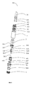
FIG. 2 is an exploded isometric view of a heating assembly of the atomizer ofFIG. 1 . -
FIG. 3 is an isometric view of a heating wire component of the heating assembly ofFIG. 2 . -
FIG. 4 is an exploded isometric view of the atomizer ofFIG. 1 . -
FIG. 5 is a schematic plan view showing a spatial relationship among a rotary table, two positive beads, and two insulative beads of the atomizer ofFIG. 1 . -
FIG. 6 is a cross sectional view of an atomizer according to a second embodiment, taken along a surface passing a central axis thereof. -
FIG. 7 is a schematic view of an air tube and internal components in the air tube ofFIG. 2 . -
FIG. 8 is another cross sectional view of atomizer ofFIG. 1 taken along another surface passing the central axis. -
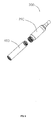
FIG. 9 is a partly exploded isometric view of an electronic cigarette according to a third embodiment. - Embodiments of the present atomizer and electronic cigarette will now be described in detail below and with references to the drawings.
- Referring to
FIG. 1 , anatomizer 100 for electronic cigarette according to a first embodiment, mainly includes amouthpiece assembly 1, twoheating assemblies 2, a fixing assembly 3, an atomizingsleeve 4, and aswitching assembly 5. - One end of each
heating assembly 2 is engaged with themouthpiece assembly 1. The twoheating assemblies 2 are configured (i.e., structured and arranged) for heating and atomizing oils of different tastes. The fixing assembly 3 is hermetically coupled to themouthpiece assembly 1, and configured for securing the twoheating assemblies 2. The atomizingsleeve 4 is hermetically coupled to the fixing assembly 3, with the twoheating assemblies 2 received therein. Ends of the two heating assemblies 2 away from themouthpiece assembly 1, are connected to theswitching assembly 5. Theswitching assembly 5 is adapted for enabling (i.e., powering on) one of two heating assemblies selectively. The atomizingsleeve 4 can be made of organic glass, crystal, or other materials of high transparency. - Referring also to
FIG. 3 , themouthpiece assembly 1 includes amouthpiece 101, and afixture 103. Themouthpiece 101 is mounted on thefixture 103 via alatch 102. Themouthpiece 101 defines two throughholes 104. Themouthpiece 101 may be soft or hard. The twoheating assemblies 2 are coupled to the two throughholes 104 respectively viaseal sleeves 105. The position between theheating assemblies 2 and the throughholes 104 is fixed. - The fixing assembly 3 includes an
upper holder 301 and alower holder 302. One end of theupper holder 301 is connected to thefixture 103, and the other end of theupper holder 301 is connected to one end of the atomizingsleeve 4 by aseal ring 303. In the present embodiment, theupper holder 301 is threadedly coupled to the atomizingsleeve 4. One end of thelower holder 302 is hermetically connected to the other end of the atomizingsleeve 4, the other end of thelower holder 302 is connected to theswitching assembly 5. Thelower holder 302 defines two throughholes 304, so that eachheating assembly 2 can extend through the throughholes 304 to be electrically connected to theswitching assembly 5. - Referring to
FIG. 2 , eachheating assembly 2 sequentially includes amouthpiece seal sleeve 201, amouthpiece seal gaskets 202, aheating wire component 203, anair pipe 204, atubular electrode 205, and aninsulative ring 206. Theair pipe 204 is configured for supporting theheating wire component 203, and providing an air passage. Theinsulative ring 206 is disposed between thetubular electrode 205 and theair pipe 204, so that thetubular electrode 205 is insulative from theair pipe 204. Theheating assembly 2 is hermetically connected to the throughhole 104 of themouthpiece assembly 1 via themouthpiece 201. Theair tube 204, the atomizingsleeve 4, theupper holder 301 and thelower holder 302 cooperatively form a sealed space as an oil reserving chamber. The atomizingsleeve 4 includes a spacer, which divides the oil reserving chamber into two separate sub-chambers for reserving oils of different tastes. Eachheating assembly 2 is configured for heating oil of a sub-chamber. - The
air tube 204 is connected to a negative electrode of a battery. Thetubular electrode 205 is connected to a positive electrode of the battery. - Referring to
FIG. 3 , theheating wire component 203 includes aheating wire 31, aglass fiber core 32, aglass fiber tube 33, and asilicon base 34. Theheating wire 31 is wound around theglass fiber core 32. Two ends of theheating wire 31 are connected to the positive and negative electrodes of the battery, respectively. In this way, theheating wire 31 is heated. - Referring to
FIGs. 4-5 , theswitching assembly 5 mainly includes a rotary table 501, twopositive beads 502, twoinsulative beads 503, aseat 504, apositive spring 505, a positivecylindrical electrode 506, a shielding plate 507, ascrewed sleeve 508, anegative spring 509, anelastic plate 510, aswitching base 511, and twopins 512. Thepositive beads 502 and theinsulative beads 503 are arranged on theseat 504. Theseat 504 is fixed on the rotary table 501. The positivecylindrical electrode 506 is fixed at a center of the rotary table 501, and is electrically connected to thepositive beads 502. The shielding plate 507 is for shielding internal components, so that internal structure of the switchingassembly 5 looks simple. The screwedsleeve 508 is fixed with the rotary table 501, electrically connected to the negative electrode of the battery, and is configured for threadedly coupling to a battery assembly (not shown). Thenegative spring 509 is electrically connected to the screwedsleeve 508 and theswitching base 511, and makes sure reliability of connection to the negative electrode. The switchingbase 511 is fixedly coupled to the fixing assembly 3. Theelastic plate 510 is engaged with thelower holder 302. The rotary table 501 is rotatable around a central axis 5011 thereof relative theswitching base 511. The positivecylindrical electrode 506 is connected to the positive electrode of the battery. - Each
positive bead 502 is corresponding to aninsulative bead 503. Eachpositive bead 502 and acorresponding insulative bead 503 are arranged spatially corresponding to the twoheating assemblies 2. When oneheating assembly 2 aligns with one of thepositive beads 502 and electrically contacts the one of thepositive beads 502, theother heating assembly 2 aligns with the other of theinsulative beads 503, contacts the other of theinsulative beads 503, and is disconnected from the positive electrode of the battery. A central axis of eachpositive bead 502 and a central axis of acorresponding insulative bead 503 are symmetric about the central axis 5011 of the rotary table 501. The twopositive beads 502 and the twoinsulative beads 503 are arranged in a circle centered at a center of the rotary table 501. A distance between eachpositive bead 502 and thecorresponding insulative bead 503 is substantially equal to that between the twoheating assemblies 2. At one time, only oneheating assembly 2 is powered on, and accordingly, oil of only one taste is heated and atomized. - The rotary table 501 is capable of rotating between a first position and a second position. When the rotary table 501 is in the first position, one
heating assembly 2 is in contact with one of thepositive beads 502, and is powered on; when the rotary table 501 is in the second position, theother heating assembly 2 is in contact with the other of thepositive beads 502, and is powered on. - The shielding plate 507 is fixed on the rotary table 501 through
pins 512. The positivecylindrical electrode 506 is fixed at the center of the rotary table 501, and is clamped by thepositive spring 505. - The
atomizer 100 further includes anornament ring 6 engaged with theswitching base 511 for indicating information about smoke of current taste provided by theatomizer 100. - In the present embodiment, the
atomizer 100 includes twoheating assemblies 2, and the switchingassembly 5. The switchingassembly 5 enables one of the twoheating assemblies 2 selectively, thereby heating and atomizing oil of desired taste. Accordingly, it is very convenient for the smoker to enjoy smoke of different tastes. - Referring to
FIGS. 6-8 , anatomizer 200 according to a second embodiment is shown. Since theatomizer 200 is similar to theatomizer 100, similar structures will not be described for brevity. - The
atomizer 200 includes twoair pipes 142, anupper holder 12, twotubular electrode 147, twoheating wires 144, a shiftingbase 135, a rotary table 160, aspring 155, and an engagingportion 153. - The
upper holder 12 defines two fixing holes 121. The twoair pipes 142 are detachably coupled in the two fixing holes 121 accordingly. - In the present embodiment, each
air pipe 142 includes afirst part 142a, asecond part 142b, and amiddle part 142c detachably interconnected between thefirst part 142a and thesecond part 142b. One end of thefirst part 142a is detachably coupled to the fixing hole 121. Accordingly, when thetubular electrode 147 is damaged due to high temperature of theheating wires 144, thefirst part 142a, thetubular electrode 147 and the heating wires can be removed and replaced. Theair pipe 142 includes several parts (i.e., thefirst part 142a, etc.), so that it is convenient to replace part of theair pipe 142 and internal components (e.g., the tubular electrode 147) within theair pipe 142, without replacing thewhole air pipe 142, thereby reducing cost. - The shifting
base 135 defines afirst recess 151 and asecond recess 152 in an inner surface thereof. The first andsecond recesses spring 155 is connected to one end of the engagingportion 153. The engagingportion 153 is slidable along a longitudinal direction of thespring 155 on the rotary table 160. One end of the engagingportion 153 away from thespring 155 is also arc-shaped in cross-section, so that the engagingportion 153 matches with the first andsecond recesses 152. - In a first position, the engaging
portion 153 is pushed by thespring 155 to snapingly engage into thefirst recess 151, and oil of a first taste is heated and atomized. When the rotary table 160 is rotated to a second position, the engagingportion 153 is pushed by thespring 155 to snapingly engage into thesecond recess 152, and oil of a second taste is heated and atomized. The rotary table 160 and the engagingportion 153 make it convenient for the smoker to shift taste of the atomizer 134. - In other embodiments, the
atomizer 200 may include twoengaging portions 153, which insert into the first andsecond recesses - Referring to
FIG. 9 , anelectronic cigarette 300 according to a third embodiment includes theatomizer 200 and abattery assembly 400. Thebattery assembly 400 is threadedly coupled to one end of theatomizer 200. Theelectronic cigarette 300 can provide the smoker two different taste of smoke. It should be understood that theatomizer 200 can be replaced by theatomizer 100 ofFIG. 1 . - It is understood that the above-described embodiments are intended to illustrate rather than limit the disclosure. Variations may be made to the embodiments and methods without departing from the spirit of the disclosure. Accordingly, it is appropriate that the appended claims be construed broadly and in a manner consistent with the scope of the disclosure.
Claims (15)
- An atomizer comprising:a mouthpiece assembly;two heating assemblies configured for heating and atomizing oils of two different tastes respectively, one end of each heating assembly being engaged with the mouthpiece assembly;a fixing assembly hermetically coupled to the mouthpiece assembly,the fixing assembly being configured for securing the two heating assemblies;an atomizing sleeve hermetically connected to the fixing assembly, and nesting the two heating assemblies therein; anda switching assembly coupled to ends of the two heating assemblies away from the mouthpiece assembly, the switching assembly being configured for enabling one of two heating assemblies selectively.
- The atomizer of claim 1, wherein the fixing assembly comprises an upper holder, the upper holder is hermetically coupled to the mouthpiece assembly, the two heating assemblies each comprise an air tube, the upper holder defines two fixing holes therein, and the two air pipes are detachably coupled in the two fixing holes respectively.
- The atomizer of claim 2, wherein each air pipe comprises a first part, a second part, and a middle part detachably interconnected between the first part and the second part, one end of the first part is detachably coupled to the fixing hole.
- The atomizer according to any of preceding claims, wherein the switching assembly comprises a rotary table, two positive beads electrically connected to a positive electrode of a battery, two insulative beads, the rotary table is rotatable relative to the fixing assembly around a central axis thereof, each positive bead is corresponding to an insulative bead, each positive bead and a corresponding insulative bead are arranged spatially corresponding to the two heating assemblies, when one heating assembly aligns with one of the positive beads and electrically contacts the one of the positive beads, the other heating assembly aligns with the other of the insulative beads, contacts the other of the insulative beads, and is disconnected from the positive electrode, the rotary table is capable of rotating between a first position and a second position, when the rotary table is in the first position, one heating assembly is in contact with one of the positive beads, and is powered on; when the rotary table is in the second position, the other heating assembly is in contact with the other of the positive beads, and is powered on.
- The atomizer of claim 4, wherein a distance between each positive bead and the corresponding insulative bead is substantially equal to that between the two heating assemblies.
- The atomizer of claim 4, wherein the switching assembly further comprises a switching base, a screwed sleeve, the switching base is fixedly coupled to the fixing assembly, the screwed sleeve is fixed with the rotary table, and is configured for threadedly coupling to a battery assembly.
- The atomizer of claim 6, wherein the switching assembly further comprises a spring and an engaging portion, the spring is connected to one end of the engaging portion, the engaging portion is slidable along a longitudinal direction of the spring on the rotary table, the shifting base defines a first recess and a second recess in an inner surface thereof, when the rotary table is in a first position, the engaging portion is pushed by the spring to engage into the first recess, and oil of a first taste is heated and atomized; when the rotary table is rotated to a second position, the engaging portion is pushed by the spring to engage into the second recess, and oil of a second taste is heated and atomized.
- The atomizer of claim 6, wherein the switching assembly further comprises an ornament ring engaged with the switching base for indicating information about smoke of current taste provided by the atomizer.
- An electronic cigarette, comprising:an atomizer according to any of preceding claims; anda battery assembly configured for providing the atomizer power.
- An atomizer comprising:a mouthpiece assembly;two heating assemblies configured for heating and atomizing oil, one end of each heating assembly being engaged with the mouthpiece assembly;a fixing assembly hermetically coupled to the mouthpiece assembly,the fixing assembly being configured for securing the two heating assemblies;an atomizing sleeve hermetically connected to the fixing assembly,and nesting the two heating assemblies therein; anda switching assembly coupled to ends of the two heating assemblies away from the mouthpiece assembly, the switching assembly being configured for enabling one of two heating assemblies selectively.
- The atomizer of claim 10, wherein the fixing assembly comprises an upper holder, the upper holder is hermetically coupled to the mouthpiece assembly, the two heating assemblies each comprise an air tube, the upper holder defines two fixing holes therein, and the two air pipes are detachably coupled in the two fixing holes respectively.
- The atomizer of claim 11, wherein each air pipe comprises a first part, a second part, and a middle part detachably interconnected between the first part and the second part, one end of the first part is detachably coupled to the fixing hole.
- The atomizer of claim 10, wherein the switching assembly comprises a rotary table, two positive beads electrically connected to a positive electrode of a battery, two insulative beads, the rotary table is rotatable relative to the fixing assembly around a central axis thereof, each positive bead is corresponding to an insulative bead, each positive bead and a corresponding insulative bead are arranged spatially corresponding to the two heating assemblies, when one heating assembly aligns with one of the positive beads and electrically contacts the one of the positive beads, the other heating assembly aligns with the other of the insulative beads, contacts the other of the insulative beads, and is disconnected from the positive electrode, the rotary table is capable of rotating between a first position and a second position, when the rotary table is in the first position, one heating assembly is in contact with one of the positive beads, and is powered on; when the rotary table is in the second position, the other heating assembly is in contact with the other of the positive beads, and is powered on.
- The atomizer of claim 13, wherein the switching assembly further comprises a switching base, a screwed sleeve, the switching base is fixedly coupled to the fixing assembly, the screwed sleeve is fixed with the rotary table, and is configured for threadedly coupling to a battery assembly.
- An electronic cigarette, comprising:an atomizer according to any of claims 10-14; anda battery assembly configured for providing the atomizer power.
Applications Claiming Priority (2)
| Application Number | Priority Date | Filing Date | Title |
|---|---|---|---|
| CN201310009089.3A CN103054196B (en) | 2013-01-10 | 2013-01-10 | Electronic smoke atomizer |
| CN2013102050227A CN103271448A (en) | 2013-05-29 | 2013-05-29 | Atomizer for electronic cigarette and electronic cigarette |
Publications (2)
| Publication Number | Publication Date |
|---|---|
| EP2754361A1 true EP2754361A1 (en) | 2014-07-16 |
| EP2754361B1 EP2754361B1 (en) | 2018-03-07 |
Family
ID=49920186
Family Applications (1)
| Application Number | Title | Priority Date | Filing Date |
|---|---|---|---|
| EP14150607.1A Active EP2754361B1 (en) | 2013-01-10 | 2014-01-09 | Atomizer and electronic cigarette having same |
Country Status (2)
| Country | Link |
|---|---|
| US (1) | US9675117B2 (en) |
| EP (1) | EP2754361B1 (en) |
Cited By (10)
| Publication number | Priority date | Publication date | Assignee | Title |
|---|---|---|---|---|
| WO2015078147A1 (en) * | 2013-11-28 | 2015-06-04 | Hk Triangle Co., Limited | Electronic cigarette atomizer |
| FR3025981A1 (en) * | 2014-09-19 | 2016-03-25 | Terry Mixtur | DEVICE FOR INHALING A GAS SUCH AS AN ELECTRONIC CIGARETTE |
| WO2016124740A1 (en) * | 2015-02-05 | 2016-08-11 | Jt International Sa | Aerosol guiding device and aerosol generating system comprising said aerosol guiding device |
| GB2536306A (en) * | 2015-03-13 | 2016-09-14 | Fontem Holdings 1 Bv | Aerosol generating component for an electronic smoking device and electronic smoking device |
| WO2019122876A1 (en) * | 2017-12-20 | 2019-06-27 | British American Tobacco (Investments) Limited | Electronic aerosol provision system |
| US10349677B2 (en) | 2015-02-05 | 2019-07-16 | Jt International S.A. | Aerosol guiding device and aerosol generating system comprising said aerosol guiding device |
| RU2737446C2 (en) * | 2016-07-28 | 2020-11-30 | Филип Моррис Продактс С.А. | Delivery of composition in e-vaping devices based on venturi effect |
| US11439183B2 (en) | 2017-02-10 | 2022-09-13 | Nicoventures Trading Limited | Vapor provision system |
| US11800898B2 (en) | 2017-12-20 | 2023-10-31 | Nicoventures Trading Limited | Electronic aerosol provision system |
| US12114694B2 (en) | 2017-12-20 | 2024-10-15 | Nicoventures Trading Limited | Electronic aerosol provision system |
Families Citing this family (77)
| Publication number | Priority date | Publication date | Assignee | Title |
|---|---|---|---|---|
| US10244793B2 (en) | 2005-07-19 | 2019-04-02 | Juul Labs, Inc. | Devices for vaporization of a substance |
| US9301547B2 (en) * | 2010-11-19 | 2016-04-05 | Huizhou Kimree Technology Co., Ltd. Shenzhen Branch | Electronic cigarette, electronic cigarette smoke capsule and atomization device thereof |
| US9271527B2 (en) * | 2012-06-20 | 2016-03-01 | Huizhou Kimree Technology Co., Ltd., Shenzhen Branch | Electronic cigarette and electronic cigarette device |
| US10517530B2 (en) | 2012-08-28 | 2019-12-31 | Juul Labs, Inc. | Methods and devices for delivering and monitoring of tobacco, nicotine, or other substances |
| AU2012388598B2 (en) * | 2012-08-31 | 2016-11-24 | Huizhou Kimree Technology Co., Ltd., Shenzhen Branch | Electronic cigarette |
| US10279934B2 (en) | 2013-03-15 | 2019-05-07 | Juul Labs, Inc. | Fillable vaporizer cartridge and method of filling |
| CN204579885U (en) * | 2013-03-29 | 2015-08-26 | 惠州市吉瑞科技有限公司 | Electronic cigarette |
| WO2014169422A1 (en) * | 2013-04-15 | 2014-10-23 | 吉瑞高新科技股份有限公司 | Electronic cigarette |
| KR102705152B1 (en) | 2013-05-06 | 2024-09-09 | 쥴 랩스, 인크. | Nicotine salt formulations for aerosol devices and methods thereof |
| CN111642812A (en) | 2013-06-14 | 2020-09-11 | 尤尔实验室有限公司 | Multiple heating elements with individual vaporizable materials in electronic vaporization devices |
| CN203290241U (en) * | 2013-07-11 | 2013-11-20 | 刘团芳 | Tobacco tar atomization device |
| CN203435687U (en) * | 2013-08-31 | 2014-02-19 | 卓尔悦(常州)电子科技有限公司 | Atomizing head |
| CN203492792U (en) * | 2013-10-15 | 2014-03-26 | 刘秋明 | Electronic cigarette |
| US10039321B2 (en) | 2013-11-12 | 2018-08-07 | Vmr Products Llc | Vaporizer |
| KR102957402B1 (en) | 2013-12-05 | 2026-04-24 | 쥴 랩스, 인크. | Nicotine liquid formulations for aerosol devices and methods thereof |
| CN203633508U (en) * | 2013-12-13 | 2014-06-11 | 深圳葆威道科技有限公司 | Dual-taste sound-making electronic cigarette |
| USD842536S1 (en) | 2016-07-28 | 2019-03-05 | Juul Labs, Inc. | Vaporizer cartridge |
| US10159282B2 (en) | 2013-12-23 | 2018-12-25 | Juul Labs, Inc. | Cartridge for use with a vaporizer device |
| USD825102S1 (en) | 2016-07-28 | 2018-08-07 | Juul Labs, Inc. | Vaporizer device with cartridge |
| US10058129B2 (en) | 2013-12-23 | 2018-08-28 | Juul Labs, Inc. | Vaporization device systems and methods |
| US10076139B2 (en) | 2013-12-23 | 2018-09-18 | Juul Labs, Inc. | Vaporizer apparatus |
| KR102721939B1 (en) | 2013-12-23 | 2024-10-25 | 쥴 랩스, 인크. | Vaporization device systems and methods |
| US20160366947A1 (en) | 2013-12-23 | 2016-12-22 | James Monsees | Vaporizer apparatus |
| US9980515B2 (en) | 2014-02-12 | 2018-05-29 | Vapor 4 Life, LLC | Mouthpiece assembly for an electronic cigar or cigarette |
| CN106028856A (en) * | 2014-02-28 | 2016-10-12 | 吉瑞高新科技股份有限公司 | Electronic cigarette and atomization control method of electronic cigarette |
| FR3019442A1 (en) * | 2014-04-04 | 2015-10-09 | Agece Ecole Centrale D Electronique | DEVICE FOR ADJUSTING A QUANTITY OF NICOTINE INHALED BY A USER AND PORTABLE TERMINAL COMMUNICATING |
| WO2015175979A1 (en) | 2014-05-16 | 2015-11-19 | Pax Labs, Inc. | Systems and methods for aerosolizing a smokeable material |
| WO2016008124A1 (en) * | 2014-07-16 | 2016-01-21 | 惠州市吉瑞科技有限公司 | Electronic cigarette having a plurality of vaporization assemblies |
| WO2016011574A1 (en) * | 2014-07-21 | 2016-01-28 | 惠州市吉瑞科技有限公司 | Electronic cigarette |
| US9220298B1 (en) | 2014-09-13 | 2015-12-29 | Viiital, LLC | Technologies for smoking |
| PL4088595T3 (en) | 2014-09-17 | 2024-04-22 | Fontem Ventures B.V. | Device for storing and vaporizing liquid media |
| US9888721B2 (en) * | 2014-10-01 | 2018-02-13 | Erik Chan | E-cigarette with segregated cartridge for selective disbursement of liquid solution flavors |
| KR20250012730A (en) | 2014-12-05 | 2025-01-24 | 쥴 랩스, 인크. | Calibrated dose control |
| CN104738816B (en) * | 2015-02-04 | 2024-08-02 | 深圳市合元科技有限公司 | Atomizer, electronic cigarette and liquid storage device suitable for replacement |
| US12245337B2 (en) | 2015-02-17 | 2025-03-04 | Mark Krietzman | Vaporizing consumables heated with convection and conduction in a portable device |
| US9894936B2 (en) * | 2015-02-17 | 2018-02-20 | Mark Krietzman | Zoned vaporizer |
| US10118013B2 (en) * | 2015-02-17 | 2018-11-06 | Mark Krietzman | Rechargeable portable aromatherapy vaporizers |
| US10893707B2 (en) | 2015-02-17 | 2021-01-19 | Mark H. Krietzman | Portable temperature controlled aromatherapy vaporizers |
| JP6827424B2 (en) * | 2015-05-06 | 2021-02-10 | アルトリア クライアント サービシーズ エルエルシー | Non-combustible smoking device and its elements |
| US20160330999A1 (en) * | 2015-05-12 | 2016-11-17 | Lunatech, Llc | Vapor delivery for simulation of food or meal flavors |
| MX377347B (en) | 2016-02-11 | 2025-03-07 | Juul Labs Inc | Fillable vaporizer cartridge and method of filling |
| MX388616B (en) | 2016-02-11 | 2025-03-20 | Juul Labs Inc | SECURE FITTING CARTRIDGES FOR VAPORIZING DEVICES |
| US10455863B2 (en) | 2016-03-03 | 2019-10-29 | Altria Client Services Llc | Cartridge for electronic vaping device |
| US10433580B2 (en) | 2016-03-03 | 2019-10-08 | Altria Client Services Llc | Methods to add menthol, botanic materials, and/or non-botanic materials to a cartridge, and/or an electronic vaping device including the cartridge |
| US10368580B2 (en) * | 2016-03-08 | 2019-08-06 | Altria Client Services Llc | Combined cartridge for electronic vaping device |
| US10405582B2 (en) | 2016-03-10 | 2019-09-10 | Pax Labs, Inc. | Vaporization device with lip sensing |
| US12501928B2 (en) | 2016-03-11 | 2025-12-23 | Altria Client Services Llc | Multiple dispersion generating e-vaping device having a dual piston cylinder, configured to reduce a transmission of a pressure force from a carbon dioxide capsule to a tank configured to store a pre-aerosol formulation |
| US10368581B2 (en) | 2016-03-11 | 2019-08-06 | Altria Client Services Llc | Multiple dispersion generator e-vaping device |
| US10357060B2 (en) | 2016-03-11 | 2019-07-23 | Altria Client Services Llc | E-vaping device cartridge holder |
| CN118319066A (en) | 2016-04-22 | 2024-07-12 | 尤尔实验室有限公司 | Aerosol device with spacer material |
| US10111468B2 (en) | 2016-06-13 | 2018-10-30 | Db Innovation Inc. | Vaporization device |
| USD849996S1 (en) | 2016-06-16 | 2019-05-28 | Pax Labs, Inc. | Vaporizer cartridge |
| USD851830S1 (en) | 2016-06-23 | 2019-06-18 | Pax Labs, Inc. | Combined vaporizer tamp and pick tool |
| USD848057S1 (en) | 2016-06-23 | 2019-05-07 | Pax Labs, Inc. | Lid for a vaporizer |
| USD836541S1 (en) | 2016-06-23 | 2018-12-25 | Pax Labs, Inc. | Charging device |
| USD816267S1 (en) | 2016-07-01 | 2018-04-24 | Db Innovation Inc. | Vaporization device |
| USD825098S1 (en) | 2016-07-01 | 2018-08-07 | Db Innovation Inc. | Vaporization device |
| USD876007S1 (en) | 2016-07-01 | 2020-02-18 | Db Innovation Inc. | Handle for a vaporizer |
| CN106037011B (en) * | 2016-07-13 | 2019-08-02 | 卓尔悦欧洲控股有限公司 | Atomising head, atomizer and electronic cigarette |
| US9993025B2 (en) | 2016-07-25 | 2018-06-12 | Fontem Holdings 1 B.V. | Refillable electronic cigarette clearomizer |
| US11019847B2 (en) | 2016-07-28 | 2021-06-01 | Rai Strategic Holdings, Inc. | Aerosol delivery devices including a selector and related methods |
| US11660403B2 (en) | 2016-09-22 | 2023-05-30 | Juul Labs, Inc. | Leak-resistant vaporizer device |
| US10433585B2 (en) | 2016-12-28 | 2019-10-08 | Altria Client Services Llc | Non-combustible smoking systems, devices and elements thereof |
| USD891609S1 (en) * | 2017-01-31 | 2020-07-28 | Philip Morris Products S.A. | Dry powder inhaler |
| USD891608S1 (en) * | 2017-01-31 | 2020-07-28 | Philip Morris Products S.A. | Dry powder inhaler |
| USD887632S1 (en) | 2017-09-14 | 2020-06-16 | Pax Labs, Inc. | Vaporizer cartridge |
| EP3813914B1 (en) | 2018-06-26 | 2023-10-25 | Juul Labs, Inc. | Vaporizer wicking elements |
| GB201812062D0 (en) * | 2018-07-24 | 2018-09-05 | Nicoventures Trading Ltd | A power module for a modular aerosol generating device, a module for a modular aerosole generating device and a modular aerosol generating device |
| US11413409B2 (en) | 2018-09-12 | 2022-08-16 | Juul Labs, Inc. | Vaporizer including positive temperature coefficient of resistivity (PTCR) heating element |
| KR20250107299A (en) | 2018-11-08 | 2025-07-11 | 쥴 랩스, 인크. | Cartridge and vaporizer device having the same |
| US11197501B1 (en) * | 2019-01-15 | 2021-12-14 | Davone Washington | Personal vaporizer having multiple liquid-holding reservoirs |
| US11607506B2 (en) * | 2019-02-22 | 2023-03-21 | Altria Client Services Llc | Electronic dispersion device |
| US11181199B2 (en) | 2019-06-04 | 2021-11-23 | 14Th Round Inc. | Assembly for preventing leakage in a vaporization device |
| CN111054569B (en) * | 2020-01-06 | 2024-09-10 | 佛山市南海科日超声电子有限公司 | Elastic ring piece for atomizing sheet and atomizing equipment |
| KR102337231B1 (en) * | 2020-02-07 | 2021-12-08 | 주식회사 케이티앤지 | An aerosol generating device and a method for controlling thereof |
| US11737493B2 (en) * | 2020-03-20 | 2023-08-29 | Tuanfang Liu | Atomization assembly and electronic cigarette comprising the same |
| CN119453564A (en) * | 2023-08-09 | 2025-02-18 | 深圳市合元科技有限公司 | Electronic atomization device |
Citations (2)
| Publication number | Priority date | Publication date | Assignee | Title |
|---|---|---|---|---|
| WO1995027411A1 (en) * | 1994-04-08 | 1995-10-19 | Philip Morris Products Inc. | Inductive heating systems for smoking articles |
| US20120260927A1 (en) * | 2010-11-19 | 2012-10-18 | Qiuming Liu | Electronic cigarette, electronic cigarette smoke capsule and atomization device thereof |
Family Cites Families (8)
| Publication number | Priority date | Publication date | Assignee | Title |
|---|---|---|---|---|
| CN201986689U (en) | 2011-03-28 | 2011-09-28 | 深圳市康泰尔电子有限公司 | Electronic cigarette |
| CN202445135U (en) | 2012-01-19 | 2012-09-26 | 湖北中烟工业有限责任公司 | Double-channel electronic atomizing cigarette |
| EP2836090B1 (en) * | 2012-04-12 | 2019-03-06 | JT International SA | Aerosol-generating devices |
| CN202603608U (en) | 2012-05-17 | 2012-12-19 | 深圳市康尔科技有限公司 | Electronic cigarette |
| US8881737B2 (en) * | 2012-09-04 | 2014-11-11 | R.J. Reynolds Tobacco Company | Electronic smoking article comprising one or more microheaters |
| US20140123989A1 (en) * | 2012-11-05 | 2014-05-08 | The Safe Cig, Llc | Device and method for vaporizing a fluid |
| CN203072894U (en) | 2013-01-10 | 2013-07-24 | 深圳市合元科技有限公司 | Electronic cigarette atomizer |
| CN103054196B (en) | 2013-01-10 | 2016-03-02 | 深圳市合元科技有限公司 | Electronic smoke atomizer |
-
2014
- 2014-01-09 EP EP14150607.1A patent/EP2754361B1/en active Active
- 2014-01-10 US US14/152,572 patent/US9675117B2/en active Active
Patent Citations (2)
| Publication number | Priority date | Publication date | Assignee | Title |
|---|---|---|---|---|
| WO1995027411A1 (en) * | 1994-04-08 | 1995-10-19 | Philip Morris Products Inc. | Inductive heating systems for smoking articles |
| US20120260927A1 (en) * | 2010-11-19 | 2012-10-18 | Qiuming Liu | Electronic cigarette, electronic cigarette smoke capsule and atomization device thereof |
Cited By (18)
| Publication number | Priority date | Publication date | Assignee | Title |
|---|---|---|---|---|
| WO2015078147A1 (en) * | 2013-11-28 | 2015-06-04 | Hk Triangle Co., Limited | Electronic cigarette atomizer |
| FR3025981A1 (en) * | 2014-09-19 | 2016-03-25 | Terry Mixtur | DEVICE FOR INHALING A GAS SUCH AS AN ELECTRONIC CIGARETTE |
| US10349677B2 (en) | 2015-02-05 | 2019-07-16 | Jt International S.A. | Aerosol guiding device and aerosol generating system comprising said aerosol guiding device |
| EP3253237B1 (en) | 2015-02-05 | 2019-04-10 | JT International SA | Aerosol guiding device and aerosol generating system comprising said aerosol guiding device |
| US10334884B2 (en) | 2015-02-05 | 2019-07-02 | Jt International S.A. | Aerosol guiding device and aerosol generating system comprising said aerosol guiding device |
| WO2016124740A1 (en) * | 2015-02-05 | 2016-08-11 | Jt International Sa | Aerosol guiding device and aerosol generating system comprising said aerosol guiding device |
| US10609964B2 (en) | 2015-02-05 | 2020-04-07 | Jt International S.A. | Aerosol guiding device and aerosol generating system comprising said aerosol guiding device |
| EA035437B1 (en) * | 2015-02-05 | 2020-06-15 | ДжейТи ИНТЕРНЭШНЛ СА | AEROSOL DIRECTION DEVICE AND AEROSOL GENERATION SYSTEM CONTAINING THE SPECIFIED AEROSOL DIRECTION DEVICE |
| US10306925B2 (en) | 2015-03-13 | 2019-06-04 | Fontem Holdings 1 B.V. | Aerosol generating component for an electronic smoking device and electronic smoking device |
| GB2536306A (en) * | 2015-03-13 | 2016-09-14 | Fontem Holdings 1 Bv | Aerosol generating component for an electronic smoking device and electronic smoking device |
| RU2737446C2 (en) * | 2016-07-28 | 2020-11-30 | Филип Моррис Продактс С.А. | Delivery of composition in e-vaping devices based on venturi effect |
| US11439183B2 (en) | 2017-02-10 | 2022-09-13 | Nicoventures Trading Limited | Vapor provision system |
| WO2019122876A1 (en) * | 2017-12-20 | 2019-06-27 | British American Tobacco (Investments) Limited | Electronic aerosol provision system |
| RU2751940C1 (en) * | 2017-12-20 | 2021-07-21 | Никовенчерс Трейдинг Лимитед | Electronic aerosol delivery system |
| US11800898B2 (en) | 2017-12-20 | 2023-10-31 | Nicoventures Trading Limited | Electronic aerosol provision system |
| US11871795B2 (en) | 2017-12-20 | 2024-01-16 | Nicoventures Trading Limited | Electronic aerosol provision system |
| US12114694B2 (en) | 2017-12-20 | 2024-10-15 | Nicoventures Trading Limited | Electronic aerosol provision system |
| US12357031B2 (en) | 2017-12-20 | 2025-07-15 | Nicoventures Trading Limited | Electronic aerosol provision system |
Also Published As
| Publication number | Publication date |
|---|---|
| US20140190503A1 (en) | 2014-07-10 |
| US9675117B2 (en) | 2017-06-13 |
| EP2754361B1 (en) | 2018-03-07 |
Similar Documents
| Publication | Publication Date | Title |
|---|---|---|
| US9675117B2 (en) | Atomizer for electronic cigarette and electronic cigarette having the same | |
| US10070668B2 (en) | Replaceable atomizing unit, atomizer and electronic cigarette having same | |
| CN103054196B (en) | Electronic smoke atomizer | |
| US9089168B2 (en) | Electronic cigarette | |
| EP2870889B1 (en) | Atomizing assembly, atomizer and electronic cigarette having same | |
| US9538790B2 (en) | Atomizing device and electronic cigarette having same | |
| US9848650B2 (en) | Atomizer and aerosol inhaling device having same | |
| US9999248B2 (en) | Electronic cigarette and method for assembling electronic cigarette | |
| US9301549B2 (en) | Electronic cigarette device, electronic cigarette and atomization device thereof | |
| US9848646B2 (en) | Electronic cigarette and battery device thereof | |
| US20170224017A1 (en) | Electronic cigarette | |
| CN104000305B (en) | Electronic cigarette | |
| US9532598B2 (en) | Electronic cigarette atomizer | |
| CN101627837B (en) | Electronic cigarette | |
| US20140332022A1 (en) | Atomizing device and electronic cigarette having same | |
| US20150196055A1 (en) | Electronic cigarette | |
| US20140366895A1 (en) | Battery assembly and electronic cigarette | |
| US20160106152A1 (en) | Electronic cigarette and air switch thereof | |
| WO2015109633A1 (en) | Battery rod and electronic cigarette | |
| CN103271448A (en) | Atomizer for electronic cigarette and electronic cigarette | |
| CN104223368A (en) | Electronic cigarette atomizer | |
| CN203072894U (en) | Electronic cigarette atomizer | |
| CN201499601U (en) | electronic cigarette | |
| CN203555163U (en) | Battery assembly used for electronic cigarette and electronic cigarette | |
| CN204157652U (en) | Electronic smoke atomizer |
Legal Events
| Date | Code | Title | Description |
|---|---|---|---|
| PUAI | Public reference made under article 153(3) epc to a published international application that has entered the european phase |
Free format text: ORIGINAL CODE: 0009012 |
|
| 17P | Request for examination filed |
Effective date: 20140109 |
|
| AK | Designated contracting states |
Kind code of ref document: A1 Designated state(s): AL AT BE BG CH CY CZ DE DK EE ES FI FR GB GR HR HU IE IS IT LI LT LU LV MC MK MT NL NO PL PT RO RS SE SI SK SM TR |
|
| AX | Request for extension of the european patent |
Extension state: BA ME |
|
| R17P | Request for examination filed (corrected) |
Effective date: 20141210 |
|
| RBV | Designated contracting states (corrected) |
Designated state(s): AL AT BE BG CH CY CZ DE DK EE ES FI FR GB GR HR HU IE IS IT LI LT LU LV MC MK MT NL NO PL PT RO RS SE SI SK SM TR |
|
| GRAP | Despatch of communication of intention to grant a patent |
Free format text: ORIGINAL CODE: EPIDOSNIGR1 |
|
| STAA | Information on the status of an ep patent application or granted ep patent |
Free format text: STATUS: GRANT OF PATENT IS INTENDED |
|
| INTG | Intention to grant announced |
Effective date: 20170831 |
|
| GRAS | Grant fee paid |
Free format text: ORIGINAL CODE: EPIDOSNIGR3 |
|
| GRAA | (expected) grant |
Free format text: ORIGINAL CODE: 0009210 |
|
| STAA | Information on the status of an ep patent application or granted ep patent |
Free format text: STATUS: THE PATENT HAS BEEN GRANTED |
|
| AK | Designated contracting states |
Kind code of ref document: B1 Designated state(s): AL AT BE BG CH CY CZ DE DK EE ES FI FR GB GR HR HU IE IS IT LI LT LU LV MC MK MT NL NO PL PT RO RS SE SI SK SM TR |
|
| REG | Reference to a national code |
Ref country code: GB Ref legal event code: FG4D |
|
| REG | Reference to a national code |
Ref country code: CH Ref legal event code: EP Ref country code: AT Ref legal event code: REF Ref document number: 975565 Country of ref document: AT Kind code of ref document: T Effective date: 20180315 |
|
| REG | Reference to a national code |
Ref country code: IE Ref legal event code: FG4D |
|
| REG | Reference to a national code |
Ref country code: DE Ref legal event code: R096 Ref document number: 602014021849 Country of ref document: DE |
|
| REG | Reference to a national code |
Ref country code: NL Ref legal event code: FP |
|
| REG | Reference to a national code |
Ref country code: LT Ref legal event code: MG4D |
|
| PG25 | Lapsed in a contracting state [announced via postgrant information from national office to epo] |
Ref country code: FI Free format text: LAPSE BECAUSE OF FAILURE TO SUBMIT A TRANSLATION OF THE DESCRIPTION OR TO PAY THE FEE WITHIN THE PRESCRIBED TIME-LIMIT Effective date: 20180307 Ref country code: NO Free format text: LAPSE BECAUSE OF FAILURE TO SUBMIT A TRANSLATION OF THE DESCRIPTION OR TO PAY THE FEE WITHIN THE PRESCRIBED TIME-LIMIT Effective date: 20180607 Ref country code: HR Free format text: LAPSE BECAUSE OF FAILURE TO SUBMIT A TRANSLATION OF THE DESCRIPTION OR TO PAY THE FEE WITHIN THE PRESCRIBED TIME-LIMIT Effective date: 20180307 Ref country code: LT Free format text: LAPSE BECAUSE OF FAILURE TO SUBMIT A TRANSLATION OF THE DESCRIPTION OR TO PAY THE FEE WITHIN THE PRESCRIBED TIME-LIMIT Effective date: 20180307 Ref country code: ES Free format text: LAPSE BECAUSE OF FAILURE TO SUBMIT A TRANSLATION OF THE DESCRIPTION OR TO PAY THE FEE WITHIN THE PRESCRIBED TIME-LIMIT Effective date: 20180307 Ref country code: CY Free format text: LAPSE BECAUSE OF FAILURE TO SUBMIT A TRANSLATION OF THE DESCRIPTION OR TO PAY THE FEE WITHIN THE PRESCRIBED TIME-LIMIT Effective date: 20180307 |
|
| REG | Reference to a national code |
Ref country code: AT Ref legal event code: MK05 Ref document number: 975565 Country of ref document: AT Kind code of ref document: T Effective date: 20180307 |
|
| PG25 | Lapsed in a contracting state [announced via postgrant information from national office to epo] |
Ref country code: GR Free format text: LAPSE BECAUSE OF FAILURE TO SUBMIT A TRANSLATION OF THE DESCRIPTION OR TO PAY THE FEE WITHIN THE PRESCRIBED TIME-LIMIT Effective date: 20180608 Ref country code: LV Free format text: LAPSE BECAUSE OF FAILURE TO SUBMIT A TRANSLATION OF THE DESCRIPTION OR TO PAY THE FEE WITHIN THE PRESCRIBED TIME-LIMIT Effective date: 20180307 Ref country code: SE Free format text: LAPSE BECAUSE OF FAILURE TO SUBMIT A TRANSLATION OF THE DESCRIPTION OR TO PAY THE FEE WITHIN THE PRESCRIBED TIME-LIMIT Effective date: 20180307 Ref country code: RS Free format text: LAPSE BECAUSE OF FAILURE TO SUBMIT A TRANSLATION OF THE DESCRIPTION OR TO PAY THE FEE WITHIN THE PRESCRIBED TIME-LIMIT Effective date: 20180307 Ref country code: BG Free format text: LAPSE BECAUSE OF FAILURE TO SUBMIT A TRANSLATION OF THE DESCRIPTION OR TO PAY THE FEE WITHIN THE PRESCRIBED TIME-LIMIT Effective date: 20180607 |
|
| PG25 | Lapsed in a contracting state [announced via postgrant information from national office to epo] |
Ref country code: PL Free format text: LAPSE BECAUSE OF FAILURE TO SUBMIT A TRANSLATION OF THE DESCRIPTION OR TO PAY THE FEE WITHIN THE PRESCRIBED TIME-LIMIT Effective date: 20180307 Ref country code: EE Free format text: LAPSE BECAUSE OF FAILURE TO SUBMIT A TRANSLATION OF THE DESCRIPTION OR TO PAY THE FEE WITHIN THE PRESCRIBED TIME-LIMIT Effective date: 20180307 Ref country code: AL Free format text: LAPSE BECAUSE OF FAILURE TO SUBMIT A TRANSLATION OF THE DESCRIPTION OR TO PAY THE FEE WITHIN THE PRESCRIBED TIME-LIMIT Effective date: 20180307 Ref country code: RO Free format text: LAPSE BECAUSE OF FAILURE TO SUBMIT A TRANSLATION OF THE DESCRIPTION OR TO PAY THE FEE WITHIN THE PRESCRIBED TIME-LIMIT Effective date: 20180307 |
|
| PG25 | Lapsed in a contracting state [announced via postgrant information from national office to epo] |
Ref country code: CZ Free format text: LAPSE BECAUSE OF FAILURE TO SUBMIT A TRANSLATION OF THE DESCRIPTION OR TO PAY THE FEE WITHIN THE PRESCRIBED TIME-LIMIT Effective date: 20180307 Ref country code: SM Free format text: LAPSE BECAUSE OF FAILURE TO SUBMIT A TRANSLATION OF THE DESCRIPTION OR TO PAY THE FEE WITHIN THE PRESCRIBED TIME-LIMIT Effective date: 20180307 Ref country code: AT Free format text: LAPSE BECAUSE OF FAILURE TO SUBMIT A TRANSLATION OF THE DESCRIPTION OR TO PAY THE FEE WITHIN THE PRESCRIBED TIME-LIMIT Effective date: 20180307 Ref country code: SK Free format text: LAPSE BECAUSE OF FAILURE TO SUBMIT A TRANSLATION OF THE DESCRIPTION OR TO PAY THE FEE WITHIN THE PRESCRIBED TIME-LIMIT Effective date: 20180307 |
|
| REG | Reference to a national code |
Ref country code: DE Ref legal event code: R097 Ref document number: 602014021849 Country of ref document: DE |
|
| PG25 | Lapsed in a contracting state [announced via postgrant information from national office to epo] |
Ref country code: PT Free format text: LAPSE BECAUSE OF FAILURE TO SUBMIT A TRANSLATION OF THE DESCRIPTION OR TO PAY THE FEE WITHIN THE PRESCRIBED TIME-LIMIT Effective date: 20180709 |
|
| PLBE | No opposition filed within time limit |
Free format text: ORIGINAL CODE: 0009261 |
|
| STAA | Information on the status of an ep patent application or granted ep patent |
Free format text: STATUS: NO OPPOSITION FILED WITHIN TIME LIMIT |
|
| PG25 | Lapsed in a contracting state [announced via postgrant information from national office to epo] |
Ref country code: DK Free format text: LAPSE BECAUSE OF FAILURE TO SUBMIT A TRANSLATION OF THE DESCRIPTION OR TO PAY THE FEE WITHIN THE PRESCRIBED TIME-LIMIT Effective date: 20180307 |
|
| 26N | No opposition filed |
Effective date: 20181210 |
|
| PG25 | Lapsed in a contracting state [announced via postgrant information from national office to epo] |
Ref country code: SI Free format text: LAPSE BECAUSE OF FAILURE TO SUBMIT A TRANSLATION OF THE DESCRIPTION OR TO PAY THE FEE WITHIN THE PRESCRIBED TIME-LIMIT Effective date: 20180307 |
|
| PG25 | Lapsed in a contracting state [announced via postgrant information from national office to epo] |
Ref country code: MC Free format text: LAPSE BECAUSE OF FAILURE TO SUBMIT A TRANSLATION OF THE DESCRIPTION OR TO PAY THE FEE WITHIN THE PRESCRIBED TIME-LIMIT Effective date: 20180307 |
|
| PG25 | Lapsed in a contracting state [announced via postgrant information from national office to epo] |
Ref country code: LU Free format text: LAPSE BECAUSE OF NON-PAYMENT OF DUE FEES Effective date: 20190109 |
|
| REG | Reference to a national code |
Ref country code: BE Ref legal event code: MM Effective date: 20190131 |
|
| PG25 | Lapsed in a contracting state [announced via postgrant information from national office to epo] |
Ref country code: BE Free format text: LAPSE BECAUSE OF NON-PAYMENT OF DUE FEES Effective date: 20190131 |
|
| PG25 | Lapsed in a contracting state [announced via postgrant information from national office to epo] |
Ref country code: TR Free format text: LAPSE BECAUSE OF FAILURE TO SUBMIT A TRANSLATION OF THE DESCRIPTION OR TO PAY THE FEE WITHIN THE PRESCRIBED TIME-LIMIT Effective date: 20180307 |
|
| PG25 | Lapsed in a contracting state [announced via postgrant information from national office to epo] |
Ref country code: MT Free format text: LAPSE BECAUSE OF NON-PAYMENT OF DUE FEES Effective date: 20190109 |
|
| PG25 | Lapsed in a contracting state [announced via postgrant information from national office to epo] |
Ref country code: IS Free format text: LAPSE BECAUSE OF FAILURE TO SUBMIT A TRANSLATION OF THE DESCRIPTION OR TO PAY THE FEE WITHIN THE PRESCRIBED TIME-LIMIT Effective date: 20180707 |
|
| PG25 | Lapsed in a contracting state [announced via postgrant information from national office to epo] |
Ref country code: HU Free format text: LAPSE BECAUSE OF FAILURE TO SUBMIT A TRANSLATION OF THE DESCRIPTION OR TO PAY THE FEE WITHIN THE PRESCRIBED TIME-LIMIT; INVALID AB INITIO Effective date: 20140109 |
|
| PG25 | Lapsed in a contracting state [announced via postgrant information from national office to epo] |
Ref country code: MK Free format text: LAPSE BECAUSE OF FAILURE TO SUBMIT A TRANSLATION OF THE DESCRIPTION OR TO PAY THE FEE WITHIN THE PRESCRIBED TIME-LIMIT Effective date: 20180307 |
|
| PGFP | Annual fee paid to national office [announced via postgrant information from national office to epo] |
Ref country code: NL Payment date: 20251230 Year of fee payment: 13 |
|
| PGFP | Annual fee paid to national office [announced via postgrant information from national office to epo] |
Ref country code: IE Payment date: 20251223 Year of fee payment: 13 |
|
| REG | Reference to a national code |
Ref country code: CH Ref legal event code: U11 Free format text: ST27 STATUS EVENT CODE: U-0-0-U10-U11 (AS PROVIDED BY THE NATIONAL OFFICE) Effective date: 20260201 |
|
| PGFP | Annual fee paid to national office [announced via postgrant information from national office to epo] |
Ref country code: GB Payment date: 20260127 Year of fee payment: 13 |
|
| PGFP | Annual fee paid to national office [announced via postgrant information from national office to epo] |
Ref country code: DE Payment date: 20260114 Year of fee payment: 13 |
|
| PGFP | Annual fee paid to national office [announced via postgrant information from national office to epo] |
Ref country code: IT Payment date: 20260108 Year of fee payment: 13 |
|
| PGFP | Annual fee paid to national office [announced via postgrant information from national office to epo] |
Ref country code: FR Payment date: 20260128 Year of fee payment: 13 |
|
| PGFP | Annual fee paid to national office [announced via postgrant information from national office to epo] |
Ref country code: CH Payment date: 20260201 Year of fee payment: 13 |