EP2753398B1 - System for providing targeted electrical stimulation to tissue - Google Patents
System for providing targeted electrical stimulation to tissue Download PDFInfo
- Publication number
- EP2753398B1 EP2753398B1 EP12830817.8A EP12830817A EP2753398B1 EP 2753398 B1 EP2753398 B1 EP 2753398B1 EP 12830817 A EP12830817 A EP 12830817A EP 2753398 B1 EP2753398 B1 EP 2753398B1
- Authority
- EP
- European Patent Office
- Prior art keywords
- electrode
- probe
- stimulator according
- conductive surface
- handle
- Prior art date
- Legal status (The legal status is an assumption and is not a legal conclusion. Google has not performed a legal analysis and makes no representation as to the accuracy of the status listed.)
- Active
Links
Images


Classifications
-
- A—HUMAN NECESSITIES
- A61—MEDICAL OR VETERINARY SCIENCE; HYGIENE
- A61N—ELECTROTHERAPY; MAGNETOTHERAPY; RADIATION THERAPY; ULTRASOUND THERAPY
- A61N1/00—Electrotherapy; Circuits therefor
- A61N1/02—Details
- A61N1/04—Electrodes
- A61N1/05—Electrodes for implantation or insertion into the body, e.g. heart electrode
- A61N1/0551—Spinal or peripheral nerve electrodes
-
- A—HUMAN NECESSITIES
- A61—MEDICAL OR VETERINARY SCIENCE; HYGIENE
- A61B—DIAGNOSIS; SURGERY; IDENTIFICATION
- A61B5/00—Measuring for diagnostic purposes; Identification of persons
- A61B5/0048—Detecting, measuring or recording by applying mechanical forces or stimuli
-
- A—HUMAN NECESSITIES
- A61—MEDICAL OR VETERINARY SCIENCE; HYGIENE
- A61N—ELECTROTHERAPY; MAGNETOTHERAPY; RADIATION THERAPY; ULTRASOUND THERAPY
- A61N1/00—Electrotherapy; Circuits therefor
- A61N1/18—Applying electric currents by contact electrodes
- A61N1/32—Applying electric currents by contact electrodes alternating or intermittent currents
- A61N1/36—Applying electric currents by contact electrodes alternating or intermittent currents for stimulation
- A61N1/36014—External stimulators, e.g. with patch electrodes
- A61N1/36017—External stimulators, e.g. with patch electrodes with leads or electrodes penetrating the skin
Definitions
- Embodiments according to the present description relate to electrical stimulation devices, and more particularly to configurations of electrical stimulation probes and communication of information from an electrical stimulation device.
- Prior electrical stimulation apparatuses are known. Generally, however, only a portion of the probe's conductive surface (the end of the tip in contact with the tissue and the small meniscus of body fluid that forms to that tip) delivers stimulus current to tissue as the device is used in open surgical procedures. In arthroscopic procedures, however, at least some of the probe, and perhaps the entire probe, may be exposed to fluid (nominally saline), leading to concerns consistent with informal intraoperative experience that the stimulus current may be shunted away from the 5mm long conductive tip by the surrounding saline. Such shunting reduces the current flowing from the tip into the tissue to a level too low to desirably activate target nerves innervating the tissue, even when the probe is contacting tissue directly over the target nerve.
- fluid nominal saline
- a stimulation control device may incorporate a range of low and high intensity stimulation to provide a stimulation and evaluation of both nerves and muscles.
- a stimulation control device is removably coupled to a surgical device or is imbedded within the medical device to provide a stimulation and treatment medical device.
- a disposable hand held stimulation system includes an operative element extending from the housing, the housing includes a visual indication to provide feedback or status to the user.
- US 6,159,194 describes methods for performing electrosurgical interventions, such as selectively contracting soft collagen tissue and other body structures, while limiting thermal damage or molecular dissociation of such tissue and limiting the thermal damage to tissue adjacent to and underlying the treatment site.
- a method for contracting collagen tissue at a target site on or within a patient's body comprises heating an electrically conducting fluid in the region of the target site; and directing the heated electrically conducting fluid onto tissue at the target site to induce contraction of collagen fibers in said tissue.
- US 2006/200219 describes a system for differentiating or identifying targeted tissue regions locally innervated by a targeted nerve, the system comprising a hand held instrument including an electrode configuration for applying an electrical stimulation current to a tissue region, the hand held instrument including a handle, an electrical stimulation control circuitry carried within the handle, and at least one controller carried on the handle and coupled to the control circuitry for selectively altering at least one operating parameter of the control circuitry, and a second device that indicates a physiologic response to the presence or absence of the electrical stimulation current.
- Embodiments of a probe according to the present description include a cathode located on a distal tip of a probe and a proximally located anode on the probe, which is spaced some insulative distance from the cathode.
- a preferred cathode has a conductive surface area of preferably less than or equal to ten square millimeters.
- a preferred anode provides a cylindrical electrically conductive surface that is greater in area than the exposed, electrically conductive surface of the cathode, preferably greater than nine times that of the cathode.
- the insulative distance between the exposed electrically conductive cathode surface and the exposed electrically conductive anode surface is preferably at least three millimeters and more preferably five to ten millimeters.
- Probe constructions according to the present decription may be beneficially exploited in arthroscopic procedures, in which targeted electrical stimulation is desirable to be applied to tissue that may be covered in a pool or volume of conductive solution, such as saline solution.
- conductive solution such as saline solution.
- both electrode surfaces would be surrounded by saline which was previously or simultaneously infused to fill a surgical site.
- only a portion of the electrically conductive anode surface may be disposed within the saline solution.
- all probe features are sized to enable passage through a 5mm (inner diameter) arthroscopic surgical cannula. Although both electrodes are physically near one another, the construction and usage are such that the probe generates an essentially monopolar stimulating field.
- the Anode (return) sleeve is spaced at least 3 mm away from the Cathode at the end of the probe, the sleeve is surrounded by saline, the sleeve has a much greater surface area than the Cathode, and the sleeve is usually not directly touching excitable tissue.
- a system according to the present description may include an improved user interface disposed at or near a junction point of a probe section of an electrical stimulator and a handle section thereof.
- FIG. 1A depicts an electrical stimulator device 10 incorporating embodiments according to the present description.
- the stimulator 10 extends from a proximal end 12 to a distal end 14.
- a handle 16 extends from the proximal end 12 towards the distal end 14.
- the handle 16 preferably houses electrical stimulation generation circuitry, which may receive control inputs from user input controls, such as an amplitude adjustment switch 20 and/or a preferably continuous pulse width adjustment slide switch 22.
- the handle 16 may also include a low (relative to the rest of the handle 16) durometer grip portion 24 to aid in manual manipulation.
- a probe 18 extends from the distal end 14 towards the proximal end 12 and is coupled to the handle 16.
- a preferred probe configuration 100 is provided at and extending from the distal end 14 towards the proximal end 12 .
- a preferred probe configuration 100 includes a first electrode 110, a second electrode 120, and a first insulative portion 130.
- the first electrode 110 has a first external electrically conductive surface 112, having a first exposed electrode surface area, which is disposed at the distal end 14 of the probe 18.
- the electrically conductive surface 112 is electrically coupled to the electrical stimulation generation circuitry that is housed in the handle 16.
- the first surface 112 which preferably serves as a stimulation cathode, has a preferred diameter 114, such as about two to about three millimeters, and more preferably about 2.5 mm.
- the second electrode 120 has a second external electrically conductive surface 122 having a second exposed electrode surface area.
- the second conductive surface 122 which is preferably at least substantially cylindrical, is spaced proximally from the first conductive surface 112 by the first insulative portion 130.
- the second conductive surface 122 may extend from the first insulative portion 130 for an electrode length 124.
- the first conductive surface 112 and the second conductive surface 122 may be formed of any desirable material, but preferably are stainless steel.
- the first conductive surface 112 also preferably extends along a desirable length 115, longitudinally distally from the first insulative portion 130.
- a preferred range of lengths 115 is from 0.00 millimeters to about 6.00 millimeters, with about 0.50 to about 5.10 millimeters being most preferred.
- the length 115 may be selected on the basis of a desired expected charge density to be experienced during use.
- Preferred cathodic charge density may be in the range of about 0.5 ⁇ C/mm2 to about 2.0 ⁇ C/mm2, while preferred anodic charge density may be in the range of greater than zero ⁇ C/mm2 to about 0.6 ⁇ C/mm2.
- a preferred surface area of a cathodic surface is generally about 1 mm 2 to about 20 mm 2 , with about 1.6 mm 2 to about 16 mm 2 being most preferable.
- the second exposed surface area of the second conductive surface 122 is greater than the first exposed surface area of the first conductive surface 112. More preferably, for an expected depth of saline solution disposed on a stimulation side of the animal tissue to be stimulated, a greater amount of the second surface area is exposed to the solution than the whole of the first surface area. For example, if the first exposed surface area of the first conductive surface 112 is about seven square millimeters, then the electrode length 124 should be selected so as to establish a second exposed surface area of the second conductive surface 122 that is greater than seven square millimeters.
- the second exposed surface area of the second conductive surface 122 is more than five times the first exposed surface area, and most preferably, it is at least nine times the first exposed surface area.
- the second surface area is most preferably at least 63 square millimeters.
- the second conductive surface 122 may be formed as an external surface of a conductive cylinder or other tubular member 126, which may extend a majority of a longitudinal length of the probe 18.
- the second conductive surface 122 is electrically coupled to the electrical stimulation generation circuitry contained within the handle 16, and the surface 122 preferably serves as a stimulation anode. If the member 126 is used, the first conductive surface 112 may be coupled to the stimulation circuitry by an insulated, electrically conductive filament or wire 116, which is soldered or otherwise electrically coupled to the first electrode 110.
- the first insulative portion 130 is disposed proximal to the first conductive surface 112 and operates to prevent direct proximal conduction of electrical current between the first conductive surface 112 and the second conductive surface 122 if the probe 18 is disposed in air.
- the first insulative portion 130 provides a minimum insulative gap 132 between the first conductive surface 112 and the second conductive surface 122.
- the minimum insulative gap 132 is preferably three millimeters, but even more preferably five millimeters.
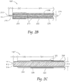
- a second preferred probe configuration 100' is shown in Figure 2B , where like numbers refer to like structure from the first embodiment 100.
- This embodiment 100' like the first embodiment 100, has a first electrode 210, a second electrode 220, and a first insulative portion 230.
- the dimensions of the second embodiment 100' are preferably similar to or the same as the first embodiment 100, but the diameter 214 of the first conductive surface 212 may be less than 2.5 mm, such as about 1 mm.
- the first conductive surface 212 also preferably extends along a desirable length 215, longitudinally distally from the first insulative portion 230.
- a preferred range of lengths 215 is from 0.00 millimeters to about 6.00 millimeters, with about 0.50 to about 5.10 millimeters being most preferred.
- the length 215 may be selected on the basis of a desired expected charge density to be experienced during use.
- Preferred cathodic charge density may be in the range of about 0.5 ⁇ C/mm2 to about 2.0 ⁇ C/mm2, while preferred anodic charge density may be in the range of greater than zero ⁇ C/mm2 to about 0.6 ⁇ C/mm2.
- a preferred surface area of a cathodic surface is generally about 1 mm 2 to about 20 mm 2 , with about 1.6 mm 2 to about 16 mm 2 being most preferable.
- the method of construction of the second embodiment 100' differs slightly from the first embodiment 100, however. While the second electrode 220 may be formed generally as a conductive tubular member 226, the first electrode 210 may be extend throughout at least a majority of the tubular member 226, but electrically insulated from contact therewith by an insulative sheath or layer 215. At the distal end of the tubular member 226, the insulative portion 230 preferably extends over such distal end and along the minimum insulative gap distance 232.
- a third preferred probe configuration 100" is shown in Figure 2C , where like numbers refer to like structure from the first embodiment 100.
- This embodiment 100 like the first embodiment 100, has a first electrode 310, a second electrode 320, and a first insulative portion 330.
- the dimensions of the second embodiment 100" are preferably similar to or the same as the first embodiment 100.
- the method of construction of the third embodiment 100" differs slightly from the first embodiment 100, however.
- the third embodiment 100" includes a partially insulated conductor with an exposed tip that forms the first electrode 310 and the first insulative portion 330.
- the second electrode 320 is provided as a conductive sleeve 326, of a desired length 324, such as about 10 millimeters (mm), that may be crimped or otherwise fastened to the insulator of the probe 18.
- the second electrode 320 is electrically coupled to the electrical stimulation generation circuitry through an electrical filament or wire 328, which may be disposed within or coupled to the insulated portion of the sheath 18.
- the first conductive surface 312 also preferably extends along a desirable length 315, longitudinally distally from the first insulative portion 330.
- a preferred range of lengths 215 is from 0.00 millimeters to about 6.00 millimeters, with about 0.50 to about 5.10 millimeters being most preferred.
- the length 315 may be selected on the basis of a desired expected charge density to be experienced during use.
- Preferred cathodic charge density may be in the range of about 0.5 ⁇ C/mm2 to about 2.0 ⁇ C/mm2, while preferred anodic charge density may be in the range of greater than zero ⁇ C/mm2 to about 0.6 ⁇ C/mm2.
- a preferred surface area of a cathodic surface is generally about 1 mm 2 to about 20 mm 2 , with about 1.6 mm 2 to about 16 mm 2 being most preferable.
- the improved user interface comprises an improved status indicator interface including a shroud 400, which may be provided at and preferably surrounding or spanning the mechanical coupling of the probe 18 to the handle 16.
- the shroud 400 extends from a proximal mounting end 402 to a distal probe end 404.
- the shroud 400 preferably includes a mounting flange or clip 406 to interface with and be captured by a portion of the handle 16.
- the shroud 400 may be formed integrally with the handle 16.
- an indicator port 408 which may be adapted to at least partially surround one or more light sources 409, such as one or more light emitting diodes that are electrically coupled to the electrical stimulation generation circuitry in the handle 16.
- a frustoconical lens surface 410 Disposed radially outwardly from the indicator port 408, and preferably on the external surface of the shroud 400, is a frustoconical lens surface 410, which may be polished.
- the frustoconical surface 410 helps to direct light from one or more light source 409 disposed at least partially within the indicator port 408 proximally towards the proximal end 12 of the device 10.
- the surface 410 preferably extends about an entire circumference of the shroud 400, though only a portion of the circumference may be used.
- the shroud 400 may also be provided without the frustoconical lens surface 410.
- the shroud 400 may be molded or otherwise formed, preferably as a unitary member, that is transparent or translucent. While the frustoconical surface 410 may be polished to enhance emission, the remainder of the external surface 412 of the shroud 400 is preferably textured in some way, such as by being bead-blasted, so as to assist in diffusion of light generated by the light sources 409. One or more of the indicated features assists in user visibility of light indications generated by the device.
- Formed into the shroud 400 is a probe bore 414 which allows passage of the probe 18 and/or electrical conductors (e.g. 116) into the shroud 400 to pass through to the circuitry in the handle 16.
- one or more light sources 409 as a status indicator may be accomplished in a number of ways.
- visual indication provided by one or more light source 409 may allow an operator of the device 10 to confirm delivery or transmission of stimulus current.
- the improved user interface may allow the operator to confirm that the instrument is powered on, and whether stimulus current is flowing.
- the operator may have a greater confidence that, where there exists a failure to elicit a desired neurological response (e.g., a muscle contraction), such failure is more likely because of lack of viable nervous tissue near or contacted by the tip (e.g. 112) of the stimulator 50 rather than equipment malfunction, power failure, or other instrumentation problems.
- one or more, or all light sources 409 may be configured to illuminate continuously in one color when the power is applied to the electrical stimulation circuitry within the handle 16 but the probe 18 is not in contact with tissue. After contact with tissue is made, one or more light sources 409 may flash (i.e., blink) or pulsate (i.e., change brightness intensity by dimming and/or brightening) to indicate that stimulation is available for delivery (i.e. stimulation would flow between the first electrode 110 and second electrode 120 if sufficient conductivity therebetween is established).
- pulsate i.e., change brightness intensity by dimming and/or brightening
- one or more light sources 409 may illuminate in a different color, and/or may illuminate continuously or may flash.
- one or more light sources 409 may operate in the following manner.
- One or more light sources 409 may provide a first indication that the stimulator 10 has not yet been turned on, that the stimulator power source has been depleted, that the stimulator has been used beyond some predetermined life span, or that an error has occurred thereby preventing stimulation.
- One or more light sources 409 may provide a second indication that the stimulator has been activated or powered on, but further that stimulation is not available for delivery.
- One or more light sources 409 may provide a third indication that the stimulator has been activated or powered on, and that greater than or equal to a first predetermined threshold of stimulus current is verified as being conducted between the first electrode and the second electrode.
- One or more light sources 409 may provide a third indication that the stimulator has been activated or powered on, and that not more than a second predetermined threshold of stimulus current is verified as being conducted between the first electrode and the second electrode.
- the mentioned indications provided by one or more light sources 409 may include display styles such as the light sources being off (i.e. not emitting light), a single color at a single intensity, intermittency (blinking) of a single color at a substantially single intensity, a single color at a varying intensity (pulsing), intermittency of a single color at varying intensity (pulsed blinking), or similar operation using a plurality of colors.
- the first indication is preferably provided by keeping all light sources off (i.e. not emitting any light).
- the second indication is preferably provided by one or more, or all, light sources 409 emitting a yellow light at a single intensity.
- the third indication is preferably provided by one or more, or all, light sources 409 emitting a blinking yellow light at a substantially single intensity.
- the third indication is preferably provided by one or more, or all, light sources 409 emitting a blinking red light at a substantially single intensity.
Landscapes
- Health & Medical Sciences (AREA)
- Life Sciences & Earth Sciences (AREA)
- Public Health (AREA)
- General Health & Medical Sciences (AREA)
- Engineering & Computer Science (AREA)
- Biomedical Technology (AREA)
- Veterinary Medicine (AREA)
- Heart & Thoracic Surgery (AREA)
- Animal Behavior & Ethology (AREA)
- Radiology & Medical Imaging (AREA)
- Nuclear Medicine, Radiotherapy & Molecular Imaging (AREA)
- Biophysics (AREA)
- Neurology (AREA)
- Neurosurgery (AREA)
- Orthopedic Medicine & Surgery (AREA)
- Cardiology (AREA)
- Physics & Mathematics (AREA)
- Pathology (AREA)
- Medical Informatics (AREA)
- Molecular Biology (AREA)
- Surgery (AREA)
- Electrotherapy Devices (AREA)
Description
- Embodiments according to the present description relate to electrical stimulation devices, and more particularly to configurations of electrical stimulation probes and communication of information from an electrical stimulation device.
- Prior electrical stimulation apparatuses are known. Generally, however, only a portion of the probe's conductive surface (the end of the tip in contact with the tissue and the small meniscus of body fluid that forms to that tip) delivers stimulus current to tissue as the device is used in open surgical procedures. In arthroscopic procedures, however, at least some of the probe, and perhaps the entire probe, may be exposed to fluid (nominally saline), leading to concerns consistent with informal intraoperative experience that the stimulus current may be shunted away from the 5mm long conductive tip by the surrounding saline. Such shunting reduces the current flowing from the tip into the tissue to a level too low to desirably activate target nerves innervating the tissue, even when the probe is contacting tissue directly over the target nerve.
-
US 2011/125051 ) describes a stimulation control device may incorporate a range of low and high intensity stimulation to provide a stimulation and evaluation of both nerves and muscles. A stimulation control device is removably coupled to a surgical device or is imbedded within the medical device to provide a stimulation and treatment medical device. A disposable hand held stimulation system includes an operative element extending from the housing, the housing includes a visual indication to provide feedback or status to the user. -
US 6,159,194 describes methods for performing electrosurgical interventions, such as selectively contracting soft collagen tissue and other body structures, while limiting thermal damage or molecular dissociation of such tissue and limiting the thermal damage to tissue adjacent to and underlying the treatment site. A method for contracting collagen tissue at a target site on or within a patient's body comprises heating an electrically conducting fluid in the region of the target site; and directing the heated electrically conducting fluid onto tissue at the target site to induce contraction of collagen fibers in said tissue. -
US 2006/200219 describes a system for differentiating or identifying targeted tissue regions locally innervated by a targeted nerve, the system comprising a hand held instrument including an electrode configuration for applying an electrical stimulation current to a tissue region, the hand held instrument including a handle, an electrical stimulation control circuitry carried within the handle, and at least one controller carried on the handle and coupled to the control circuitry for selectively altering at least one operating parameter of the control circuitry, and a second device that indicates a physiologic response to the presence or absence of the electrical stimulation current.. - Embodiments of a probe according to the present description include a cathode located on a distal tip of a probe and a proximally located anode on the probe, which is spaced some insulative distance from the cathode. A preferred cathode has a conductive surface area of preferably less than or equal to ten square millimeters. A preferred anode provides a cylindrical electrically conductive surface that is greater in area than the exposed, electrically conductive surface of the cathode, preferably greater than nine times that of the cathode. The insulative distance between the exposed electrically conductive cathode surface and the exposed electrically conductive anode surface is preferably at least three millimeters and more preferably five to ten millimeters.
- Probe constructions according to the present decription may be beneficially exploited in arthroscopic procedures, in which targeted electrical stimulation is desirable to be applied to tissue that may be covered in a pool or volume of conductive solution, such as saline solution. Preferably, in use, both electrode surfaces would be surrounded by saline which was previously or simultaneously infused to fill a surgical site. Alternatively, only a portion of the electrically conductive anode surface may be disposed within the saline solution. Preferably, all probe features are sized to enable passage through a 5mm (inner diameter) arthroscopic surgical cannula. Although both electrodes are physically near one another, the construction and usage are such that the probe generates an essentially monopolar stimulating field. Key construction & usage details include: the Anode (return) sleeve is spaced at least 3 mm away from the Cathode at the end of the probe, the sleeve is surrounded by saline, the sleeve has a much greater surface area than the Cathode, and the sleeve is usually not directly touching excitable tissue.
- A system according to the present description may include an improved user interface disposed at or near a junction point of a probe section of an electrical stimulator and a handle section thereof.
-
-
Figure 1A is a perspective view of an electrical stimulator incorporating embodiments according to the present description. -
Figure 1B is a perspective close-up view of a probe construction according to the present description. -
Figure 2A is a cross-section view of a first embodiment of a probe construction according to the present description taken alongline 2A-2A ofFigure 1B . -
Figure 2B is a cross-section view of a second embodiment of a probe construction according to the present description. -
Figure 2C is a cross-section view of a third embodiment of a probe construction according to the present description. -
Figure 3 is a partial cutaway right elevation view of the embodiment ofFigure 1A . -
Figure 4 is a partial cutaway cross-section view taken along line 4-4 ofFigure 1A . -
Figure 5 is a partial cutaway cross-section view taken along line 5-5 ofFigure 4 . - Turning now to the figures,
Figure 1A depicts anelectrical stimulator device 10 incorporating embodiments according to the present description. Thestimulator 10 extends from aproximal end 12 to adistal end 14. Ahandle 16 extends from theproximal end 12 towards thedistal end 14. Thehandle 16 preferably houses electrical stimulation generation circuitry, which may receive control inputs from user input controls, such as anamplitude adjustment switch 20 and/or a preferably continuous pulse widthadjustment slide switch 22. Thehandle 16 may also include a low (relative to the rest of the handle 16) durometer grip portion 24 to aid in manual manipulation. - A
probe 18 extends from thedistal end 14 towards theproximal end 12 and is coupled to thehandle 16. Provided at and extending from thedistal end 14 towards theproximal end 12 is apreferred probe configuration 100, as seen inFigure 1B . With reference also toFigure 2A , apreferred probe configuration 100 according to the present description includes afirst electrode 110, asecond electrode 120, and a firstinsulative portion 130. Thefirst electrode 110 has a first external electricallyconductive surface 112, having a first exposed electrode surface area, which is disposed at thedistal end 14 of theprobe 18. The electricallyconductive surface 112 is electrically coupled to the electrical stimulation generation circuitry that is housed in thehandle 16. Thefirst surface 112, which preferably serves as a stimulation cathode, has a preferreddiameter 114, such as about two to about three millimeters, and more preferably about 2.5 mm. Thesecond electrode 120 has a second external electricallyconductive surface 122 having a second exposed electrode surface area. The secondconductive surface 122, which is preferably at least substantially cylindrical, is spaced proximally from the firstconductive surface 112 by the firstinsulative portion 130. The secondconductive surface 122 may extend from the firstinsulative portion 130 for anelectrode length 124. The firstconductive surface 112 and the secondconductive surface 122 may be formed of any desirable material, but preferably are stainless steel. - The first
conductive surface 112 also preferably extends along adesirable length 115, longitudinally distally from the firstinsulative portion 130. A preferred range oflengths 115 is from 0.00 millimeters to about 6.00 millimeters, with about 0.50 to about 5.10 millimeters being most preferred. Thelength 115 may be selected on the basis of a desired expected charge density to be experienced during use. Preferred cathodic charge density may be in the range of about 0.5 µC/mm2 to about 2.0 µC/mm2, while preferred anodic charge density may be in the range of greater than zero µC/mm2 to about 0.6 µC/mm2. During use, it may be desirable to prevent tissue damage, in which case the size of thefirst electrode 110 and/orsecond electrode 120 should be sized accordingly. A preferred surface area of a cathodic surface, either theconductive surface 112 of thefirst electrode 110 or theconductive surface 122 of thesecond electrode 120, is generally about 1 mm2 to about 20 mm2, with about 1.6 mm2 to about 16 mm2 being most preferable. - Preferably, the second exposed surface area of the second
conductive surface 122 is greater than the first exposed surface area of the firstconductive surface 112. More preferably, for an expected depth of saline solution disposed on a stimulation side of the animal tissue to be stimulated, a greater amount of the second surface area is exposed to the solution than the whole of the first surface area. For example, if the first exposed surface area of the firstconductive surface 112 is about seven square millimeters, then theelectrode length 124 should be selected so as to establish a second exposed surface area of the secondconductive surface 122 that is greater than seven square millimeters. Even more preferably, the second exposed surface area of the secondconductive surface 122 is more than five times the first exposed surface area, and most preferably, it is at least nine times the first exposed surface area. Thus, in our example, if the first surface area is seven square millimeters, the second surface area is most preferably at least 63 square millimeters. - The second
conductive surface 122 may be formed as an external surface of a conductive cylinder or othertubular member 126, which may extend a majority of a longitudinal length of theprobe 18. The secondconductive surface 122 is electrically coupled to the electrical stimulation generation circuitry contained within thehandle 16, and thesurface 122 preferably serves as a stimulation anode. If themember 126 is used, the firstconductive surface 112 may be coupled to the stimulation circuitry by an insulated, electrically conductive filament orwire 116, which is soldered or otherwise electrically coupled to thefirst electrode 110. - The first
insulative portion 130 is disposed proximal to the firstconductive surface 112 and operates to prevent direct proximal conduction of electrical current between the firstconductive surface 112 and the secondconductive surface 122 if theprobe 18 is disposed in air. The firstinsulative portion 130 provides a minimuminsulative gap 132 between the firstconductive surface 112 and the secondconductive surface 122. Theminimum insulative gap 132 is preferably three millimeters, but even more preferably five millimeters. - A second preferred probe configuration 100' is shown in
Figure 2B , where like numbers refer to like structure from thefirst embodiment 100. This embodiment 100', like thefirst embodiment 100, has afirst electrode 210, asecond electrode 220, and afirst insulative portion 230. The dimensions of the second embodiment 100' are preferably similar to or the same as thefirst embodiment 100, but thediameter 214 of the firstconductive surface 212 may be less than 2.5 mm, such as about 1 mm. - The first
conductive surface 212 also preferably extends along adesirable length 215, longitudinally distally from thefirst insulative portion 230. A preferred range oflengths 215 is from 0.00 millimeters to about 6.00 millimeters, with about 0.50 to about 5.10 millimeters being most preferred. Thelength 215 may be selected on the basis of a desired expected charge density to be experienced during use. Preferred cathodic charge density may be in the range of about 0.5 µC/mm2 to about 2.0 µC/mm2, while preferred anodic charge density may be in the range of greater than zero µC/mm2 to about 0.6 µC/mm2. During use, it may be desirable to prevent tissue damage, in which case the size of thefirst electrode 210 and/orsecond electrode 220 should be sized accordingly. A preferred surface area of a cathodic surface, either theconductive surface 212 of thefirst electrode 210 or theconductive surface 222 of thesecond electrode 220, is generally about 1 mm2 to about 20 mm2, with about 1.6 mm2 to about 16 mm2 being most preferable. - The method of construction of the second embodiment 100' differs slightly from the
first embodiment 100, however. While thesecond electrode 220 may be formed generally as a conductivetubular member 226, thefirst electrode 210 may be extend throughout at least a majority of thetubular member 226, but electrically insulated from contact therewith by an insulative sheath orlayer 215. At the distal end of thetubular member 226, theinsulative portion 230 preferably extends over such distal end and along the minimuminsulative gap distance 232. - A third
preferred probe configuration 100" is shown inFigure 2C , where like numbers refer to like structure from thefirst embodiment 100. Thisembodiment 100", like thefirst embodiment 100, has afirst electrode 310, asecond electrode 320, and afirst insulative portion 330. The dimensions of thesecond embodiment 100" are preferably similar to or the same as thefirst embodiment 100. The method of construction of thethird embodiment 100" differs slightly from thefirst embodiment 100, however. Thethird embodiment 100" includes a partially insulated conductor with an exposed tip that forms thefirst electrode 310 and thefirst insulative portion 330. Thesecond electrode 320 is provided as aconductive sleeve 326, of a desired length 324, such as about 10 millimeters (mm), that may be crimped or otherwise fastened to the insulator of theprobe 18. Thesecond electrode 320 is electrically coupled to the electrical stimulation generation circuitry through an electrical filament orwire 328, which may be disposed within or coupled to the insulated portion of thesheath 18. - The first
conductive surface 312 also preferably extends along adesirable length 315, longitudinally distally from thefirst insulative portion 330. A preferred range oflengths 215 is from 0.00 millimeters to about 6.00 millimeters, with about 0.50 to about 5.10 millimeters being most preferred. Thelength 315 may be selected on the basis of a desired expected charge density to be experienced during use. Preferred cathodic charge density may be in the range of about 0.5 µC/mm2 to about 2.0 µC/mm2, while preferred anodic charge density may be in the range of greater than zero µC/mm2 to about 0.6 µC/mm2. During use, it may be desirable to prevent tissue damage, in which case the size of thefirst electrode 310 and/orsecond electrode 320 should be sized accordingly. A preferred surface area of a cathodic surface, either theconductive surface 312 of thefirst electrode 310 or theconductive surface 322 of thesecond electrode 320, is generally about 1 mm2 to about 20 mm2, with about 1.6 mm2 to about 16 mm2 being most preferable. - Turning now to
Figures 3-5 , an improved user interface may be described. The improved user interface comprises an improved status indicator interface including ashroud 400, which may be provided at and preferably surrounding or spanning the mechanical coupling of theprobe 18 to thehandle 16. Theshroud 400 extends from a proximal mountingend 402 to adistal probe end 404. At the mountingend 402, theshroud 400 preferably includes a mounting flange orclip 406 to interface with and be captured by a portion of thehandle 16. Alternatively, theshroud 400 may be formed integrally with thehandle 16. Preferably formed longitudinally into the mountingend 402 is anindicator port 408 which may be adapted to at least partially surround one or morelight sources 409, such as one or more light emitting diodes that are electrically coupled to the electrical stimulation generation circuitry in thehandle 16. Disposed radially outwardly from theindicator port 408, and preferably on the external surface of theshroud 400, is afrustoconical lens surface 410, which may be polished. Thefrustoconical surface 410 helps to direct light from one or morelight source 409 disposed at least partially within theindicator port 408 proximally towards theproximal end 12 of thedevice 10. Thesurface 410 preferably extends about an entire circumference of theshroud 400, though only a portion of the circumference may be used. Theshroud 400 may also be provided without thefrustoconical lens surface 410. Theshroud 400 may be molded or otherwise formed, preferably as a unitary member, that is transparent or translucent. While thefrustoconical surface 410 may be polished to enhance emission, the remainder of theexternal surface 412 of theshroud 400 is preferably textured in some way, such as by being bead-blasted, so as to assist in diffusion of light generated by thelight sources 409. One or more of the indicated features assists in user visibility of light indications generated by the device. Formed into theshroud 400 is aprobe bore 414 which allows passage of theprobe 18 and/or electrical conductors (e.g. 116) into theshroud 400 to pass through to the circuitry in thehandle 16. - The operation of one or more
light sources 409 as a status indicator may be accomplished in a number of ways. For instance, visual indication provided by one or morelight source 409 may allow an operator of thedevice 10 to confirm delivery or transmission of stimulus current. Through the use of different light colors, different flash rates, etc., the improved user interface may allow the operator to confirm that the instrument is powered on, and whether stimulus current is flowing. Thus the operator may have a greater confidence that, where there exists a failure to elicit a desired neurological response (e.g., a muscle contraction), such failure is more likely because of lack of viable nervous tissue near or contacted by the tip (e.g. 112) of the stimulator 50 rather than equipment malfunction, power failure, or other instrumentation problems. - As a representative example, one or more, or all
light sources 409 may be configured to illuminate continuously in one color when the power is applied to the electrical stimulation circuitry within thehandle 16 but theprobe 18 is not in contact with tissue. After contact with tissue is made, one or morelight sources 409 may flash (i.e., blink) or pulsate (i.e., change brightness intensity by dimming and/or brightening) to indicate that stimulation is available for delivery (i.e. stimulation would flow between thefirst electrode 110 andsecond electrode 120 if sufficient conductivity therebetween is established). If the stimulation has been requested, (i.e., the stimulation is available for delivery, but there is no stimulation being delivered because of a lack of sufficient conductivity between thefirst electrode 110 and the second electrode 120), one or morelight sources 409 may illuminate in a different color, and/or may illuminate continuously or may flash. - By way of further example, one or more
light sources 409 may operate in the following manner. One or morelight sources 409 may provide a first indication that thestimulator 10 has not yet been turned on, that the stimulator power source has been depleted, that the stimulator has been used beyond some predetermined life span, or that an error has occurred thereby preventing stimulation. One or morelight sources 409 may provide a second indication that the stimulator has been activated or powered on, but further that stimulation is not available for delivery. One or morelight sources 409 may provide a third indication that the stimulator has been activated or powered on, and that greater than or equal to a first predetermined threshold of stimulus current is verified as being conducted between the first electrode and the second electrode. One or morelight sources 409 may provide a third indication that the stimulator has been activated or powered on, and that not more than a second predetermined threshold of stimulus current is verified as being conducted between the first electrode and the second electrode. - The mentioned indications provided by one or more
light sources 409 may include display styles such as the light sources being off (i.e. not emitting light), a single color at a single intensity, intermittency (blinking) of a single color at a substantially single intensity, a single color at a varying intensity (pulsing), intermittency of a single color at varying intensity (pulsed blinking), or similar operation using a plurality of colors. For instance, the first indication is preferably provided by keeping all light sources off (i.e. not emitting any light). The second indication is preferably provided by one or more, or all,light sources 409 emitting a yellow light at a single intensity. The third indication is preferably provided by one or more, or all,light sources 409 emitting a blinking yellow light at a substantially single intensity. The third indication is preferably provided by one or more, or all,light sources 409 emitting a blinking red light at a substantially single intensity. - The present invention is set out in the appended claims. The embodiments, aspects or examples according to the present description that do not fall within the scope of said claims are provided for illustrative purposes only and do not form part of the present invention.
Claims (13)
- A handheld electrical stimulator (10) comprising:a handle (16) extending from a proximal end (12) to a distal end;a probe (18, 100, 100', 100") coupled to and extending away from the distal end of the handle;electrical stimulation circuitry disposed substantially within the handle;a first electrode (110, 210, 310) disposed at a distal end (14) of the probe and comprising a first conductive surface (112), wherein the first electrode is in electrical communication with the electrical stimulation circuitry;a second electrode (120, 220, 320) disposed on the probe and comprising a second conductive surface (122), wherein the second electrode is electrically insulated from the first electrode and is in electrical communication with the electrical stimulation circuitry; anda visual status indicator comprising a translucent shroud (400) having a proximal mounting end (402) coupled to the handle at a location proximal to the second electrode, an indicator port (408) formed longitudinally into the mounting end (402), and one or more light sources (409) disposed at least partially within the indicator port (408), wherein the shroud comprises a frustoconical lens surface (410) disposed about an entire perimeter of the shroud, andwherein at least a portion of the probe that is proximal to the distal end of the handle passes through an aperture (414) of the visual status indicator.
- The handheld stimulator according to claim 1, wherein the probe is straight along its entire length.
- The handheld stimulator according to claim 1, wherein the shroud extends away from the distal end of the handle and towards the distal end of the probe.
- The handheld stimulator according to claim 1, wherein the first and second electrodes are cylindrical in shape.
- The handheld stimulator according to claim 1, wherein the first electrode is a solid cylinder.
- The handheld stimulator according to claim 1, wherein the second electrode is cylindrical in shape and comprises an aperture formed therethrough.
- The handheld stimulator according to claim 6, wherein the first electrode is a solid cylinder.
- The handheld stimulator according to claim 7, wherein the probe is straight along its entire length and the first and second electrodes are disposed coaxially with each other.
- The handheld stimulator according to claim 1, wherein the surface area of the second conductive surface (122) is greater than the surface area of the first conductive surface (112).
- The handheld stimulator according to claim 9, wherein the surface area of the second conductive surface (122) is five times to nine times surface area of the first conductive surface (112).
- The handheld stimulator according to claim 1, wherein the electrical stimulation circuitry is configured for generating an electrical charge at the first electrode at a charge density level of 0.5 to 2.0 micro-coulombs.
- The handheld stimulator according to claim 11, wherein the light source is configured to generate an indication in response to a lack of sufficient conductivity between the first electrode and the second electrode.
- The handheld stimulator according to claim 1, wherein an external surface of the shroud (400) is textured to diffuse light from the one or more light sources (409).
Applications Claiming Priority (2)
| Application Number | Priority Date | Filing Date | Title |
|---|---|---|---|
| US201161532550P | 2011-09-08 | 2011-09-08 | |
| PCT/US2012/054403 WO2013036908A1 (en) | 2011-09-08 | 2012-09-10 | System for providing targeted electrical stimulation to tissue |
Publications (3)
| Publication Number | Publication Date |
|---|---|
| EP2753398A1 EP2753398A1 (en) | 2014-07-16 |
| EP2753398A4 EP2753398A4 (en) | 2015-05-20 |
| EP2753398B1 true EP2753398B1 (en) | 2020-01-08 |
Family
ID=47832628
Family Applications (1)
| Application Number | Title | Priority Date | Filing Date |
|---|---|---|---|
| EP12830817.8A Active EP2753398B1 (en) | 2011-09-08 | 2012-09-10 | System for providing targeted electrical stimulation to tissue |
Country Status (3)
| Country | Link |
|---|---|
| US (2) | US20130245490A1 (en) |
| EP (1) | EP2753398B1 (en) |
| WO (1) | WO2013036908A1 (en) |
Families Citing this family (8)
| Publication number | Priority date | Publication date | Assignee | Title |
|---|---|---|---|---|
| US11877860B2 (en) * | 2012-11-06 | 2024-01-23 | Nuvasive, Inc. | Systems and methods for performing neurophysiologic monitoring during spine surgery |
| EP3534792B1 (en) | 2016-11-03 | 2021-05-19 | EDGe Surgical, Inc. | Surgical depth instrument having neuromonitoring capabilities |
| US10792080B2 (en) | 2017-06-14 | 2020-10-06 | Edge Surgical, Inc. | Devices for minimally invasive procedures |
| CA3079849A1 (en) | 2017-10-25 | 2019-05-02 | Epineuron Technologies Inc. | Systems and methods for delivering neuroregenerative therapy |
| US10589089B2 (en) | 2017-10-25 | 2020-03-17 | Epineuron Technologies Inc. | Systems and methods for delivering neuroregenerative therapy |
| CA3091925C (en) | 2018-03-05 | 2023-01-17 | Edge Surgical, Inc. | Handheld devices for use in medical procedures |
| US11992227B2 (en) | 2018-03-05 | 2024-05-28 | Edge Surgical, Inc. | Handheld devices for use in medical procedures |
| US11247043B2 (en) | 2019-10-01 | 2022-02-15 | Epineuron Technologies Inc. | Electrode interface devices for delivery of neuroregenerative therapy |
Family Cites Families (15)
| Publication number | Priority date | Publication date | Assignee | Title |
|---|---|---|---|---|
| US2706769A (en) * | 1951-12-06 | 1955-04-19 | Cook Augustus | Hand tool |
| US4344419A (en) * | 1979-12-20 | 1982-08-17 | Kermit Burgin | Acrylooptic tongue depressor and handle therefor |
| US4892105A (en) * | 1986-03-28 | 1990-01-09 | The Cleveland Clinic Foundation | Electrical stimulus probe |
| US5012816A (en) * | 1989-08-31 | 1991-05-07 | Gabor Lederer | Electronic acupuncture device |
| CA2109793A1 (en) * | 1991-05-24 | 1992-12-10 | Stuart D. Edwards | Combination monophasic action potential/ablation catheter and high-performance filter system |
| US6159194A (en) * | 1992-01-07 | 2000-12-12 | Arthrocare Corporation | System and method for electrosurgical tissue contraction |
| US5806522A (en) * | 1995-08-15 | 1998-09-15 | Katims; Jefferson Jacob | Digital automated current perception threshold (CPT) determination device and method |
| US20020087155A1 (en) * | 1999-08-30 | 2002-07-04 | Underwood Ronald A. | Systems and methods for intradermal collagen stimulation |
| US6920883B2 (en) * | 2001-11-08 | 2005-07-26 | Arthrocare Corporation | Methods and apparatus for skin treatment |
| FR2835732B1 (en) * | 2002-02-11 | 2004-11-12 | Spinevision | DEVICE FOR TRACKING THE PENETRATION OF A PENETRATION MEANS IN ANATOMICAL ELEMENTS |
| US6888341B2 (en) * | 2003-09-16 | 2005-05-03 | Snap-On Incorporated | Dual voltage circuit tester |
| US7878981B2 (en) * | 2005-03-01 | 2011-02-01 | Checkpoint Surgical, Llc | Systems and methods for intra-operative stimulation |
| US20060200219A1 (en) * | 2005-03-01 | 2006-09-07 | Ndi Medical, Llc | Systems and methods for differentiating and/or identifying tissue regions innervated by targeted nerves for diagnostic and/or therapeutic purposes |
| EP1723983B1 (en) * | 2005-05-20 | 2013-07-10 | Imec | Probe device for electrical stimulation and recording of the activity of excitable cells |
| US20130023910A1 (en) * | 2011-07-21 | 2013-01-24 | Solomon Clifford T | Tissue-identifying surgical instrument |
-
2012
- 2012-09-07 US US13/606,862 patent/US20130245490A1/en not_active Abandoned
- 2012-09-10 WO PCT/US2012/054403 patent/WO2013036908A1/en not_active Ceased
- 2012-09-10 EP EP12830817.8A patent/EP2753398B1/en active Active
-
2022
- 2022-06-03 US US17/831,467 patent/US20220287566A1/en active Pending
Non-Patent Citations (1)
| Title |
|---|
| None * |
Also Published As
| Publication number | Publication date |
|---|---|
| US20220287566A1 (en) | 2022-09-15 |
| EP2753398A4 (en) | 2015-05-20 |
| EP2753398A1 (en) | 2014-07-16 |
| WO2013036908A1 (en) | 2013-03-14 |
| US20130245490A1 (en) | 2013-09-19 |
Similar Documents
| Publication | Publication Date | Title |
|---|---|---|
| US20220287566A1 (en) | System for providing targeted electrical stimulation to tissue | |
| US11576599B2 (en) | Stimulation device adapter | |
| US6325764B1 (en) | Bi-level charge pulse apparatus to facilitate nerve location during peripheral nerve block procedures | |
| JP5410297B2 (en) | Intraoperative stimulation system | |
| CA2538199C (en) | Systems and methods for intra-operative stimulation | |
| US20190380764A1 (en) | Plasma Accessory | |
| US6292701B1 (en) | Bipolar electrical stimulus probe with planar electrodes | |
| US8177783B2 (en) | Electric plasma-mediated cutting and coagulation of tissue and surgical apparatus | |
| US8323274B2 (en) | Ablation catheter arrangement and cooling control | |
| JP2018501825A (en) | Endoscopic pedicle probe with light source for monitoring nearby (deep needle) | |
| JP2010515487A5 (en) | ||
| US20180177385A1 (en) | Illuminated Endoscopic Pedicle Probe With Electromyographic Monitoring | |
| KR20180103815A (en) | An illuminated endoscopic pedicle probe with dynamic real-time monitoring of neural proximal location | |
| CN100558309C (en) | High frequency treatment device | |
| CN105682593B (en) | Stimulator Adapter | |
| US20240238583A1 (en) | Electrical stimulation devices and related controllers and methods | |
| KR20200097981A (en) | Electrosurgical pencil |
Legal Events
| Date | Code | Title | Description |
|---|---|---|---|
| PUAI | Public reference made under article 153(3) epc to a published international application that has entered the european phase |
Free format text: ORIGINAL CODE: 0009012 |
|
| 17P | Request for examination filed |
Effective date: 20140407 |
|
| AK | Designated contracting states |
Kind code of ref document: A1 Designated state(s): AL AT BE BG CH CY CZ DE DK EE ES FI FR GB GR HR HU IE IS IT LI LT LU LV MC MK MT NL NO PL PT RO RS SE SI SK SM TR |
|
| DAX | Request for extension of the european patent (deleted) | ||
| RA4 | Supplementary search report drawn up and despatched (corrected) |
Effective date: 20150417 |
|
| RIC1 | Information provided on ipc code assigned before grant |
Ipc: A61N 1/05 20060101ALI20150413BHEP Ipc: A61N 1/36 20060101ALI20150413BHEP Ipc: A61B 5/00 20060101ALI20150413BHEP Ipc: A61N 1/18 20060101AFI20150413BHEP |
|
| 17Q | First examination report despatched |
Effective date: 20160906 |
|
| STAA | Information on the status of an ep patent application or granted ep patent |
Free format text: STATUS: EXAMINATION IS IN PROGRESS |
|
| GRAP | Despatch of communication of intention to grant a patent |
Free format text: ORIGINAL CODE: EPIDOSNIGR1 |
|
| STAA | Information on the status of an ep patent application or granted ep patent |
Free format text: STATUS: GRANT OF PATENT IS INTENDED |
|
| INTG | Intention to grant announced |
Effective date: 20190520 |
|
| GRAS | Grant fee paid |
Free format text: ORIGINAL CODE: EPIDOSNIGR3 |
|
| GRAA | (expected) grant |
Free format text: ORIGINAL CODE: 0009210 |
|
| STAA | Information on the status of an ep patent application or granted ep patent |
Free format text: STATUS: THE PATENT HAS BEEN GRANTED |
|
| AK | Designated contracting states |
Kind code of ref document: B1 Designated state(s): AL AT BE BG CH CY CZ DE DK EE ES FI FR GB GR HR HU IE IS IT LI LT LU LV MC MK MT NL NO PL PT RO RS SE SI SK SM TR |
|
| REG | Reference to a national code |
Ref country code: GB Ref legal event code: FG4D |
|
| REG | Reference to a national code |
Ref country code: CH Ref legal event code: EP |
|
| REG | Reference to a national code |
Ref country code: DE Ref legal event code: R096 Ref document number: 602012067148 Country of ref document: DE |
|
| REG | Reference to a national code |
Ref country code: IE Ref legal event code: FG4D |
|
| REG | Reference to a national code |
Ref country code: AT Ref legal event code: REF Ref document number: 1221942 Country of ref document: AT Kind code of ref document: T Effective date: 20200215 |
|
| REG | Reference to a national code |
Ref country code: NL Ref legal event code: FP |
|
| REG | Reference to a national code |
Ref country code: LT Ref legal event code: MG4D |
|
| PG25 | Lapsed in a contracting state [announced via postgrant information from national office to epo] |
Ref country code: PT Free format text: LAPSE BECAUSE OF FAILURE TO SUBMIT A TRANSLATION OF THE DESCRIPTION OR TO PAY THE FEE WITHIN THE PRESCRIBED TIME-LIMIT Effective date: 20200531 Ref country code: RS Free format text: LAPSE BECAUSE OF FAILURE TO SUBMIT A TRANSLATION OF THE DESCRIPTION OR TO PAY THE FEE WITHIN THE PRESCRIBED TIME-LIMIT Effective date: 20200108 Ref country code: FI Free format text: LAPSE BECAUSE OF FAILURE TO SUBMIT A TRANSLATION OF THE DESCRIPTION OR TO PAY THE FEE WITHIN THE PRESCRIBED TIME-LIMIT Effective date: 20200108 Ref country code: NO Free format text: LAPSE BECAUSE OF FAILURE TO SUBMIT A TRANSLATION OF THE DESCRIPTION OR TO PAY THE FEE WITHIN THE PRESCRIBED TIME-LIMIT Effective date: 20200408 Ref country code: LT Free format text: LAPSE BECAUSE OF FAILURE TO SUBMIT A TRANSLATION OF THE DESCRIPTION OR TO PAY THE FEE WITHIN THE PRESCRIBED TIME-LIMIT Effective date: 20200108 |
|
| PG25 | Lapsed in a contracting state [announced via postgrant information from national office to epo] |
Ref country code: LV Free format text: LAPSE BECAUSE OF FAILURE TO SUBMIT A TRANSLATION OF THE DESCRIPTION OR TO PAY THE FEE WITHIN THE PRESCRIBED TIME-LIMIT Effective date: 20200108 Ref country code: BG Free format text: LAPSE BECAUSE OF FAILURE TO SUBMIT A TRANSLATION OF THE DESCRIPTION OR TO PAY THE FEE WITHIN THE PRESCRIBED TIME-LIMIT Effective date: 20200408 Ref country code: IS Free format text: LAPSE BECAUSE OF FAILURE TO SUBMIT A TRANSLATION OF THE DESCRIPTION OR TO PAY THE FEE WITHIN THE PRESCRIBED TIME-LIMIT Effective date: 20200508 Ref country code: SE Free format text: LAPSE BECAUSE OF FAILURE TO SUBMIT A TRANSLATION OF THE DESCRIPTION OR TO PAY THE FEE WITHIN THE PRESCRIBED TIME-LIMIT Effective date: 20200108 Ref country code: HR Free format text: LAPSE BECAUSE OF FAILURE TO SUBMIT A TRANSLATION OF THE DESCRIPTION OR TO PAY THE FEE WITHIN THE PRESCRIBED TIME-LIMIT Effective date: 20200108 Ref country code: GR Free format text: LAPSE BECAUSE OF FAILURE TO SUBMIT A TRANSLATION OF THE DESCRIPTION OR TO PAY THE FEE WITHIN THE PRESCRIBED TIME-LIMIT Effective date: 20200409 |
|
| REG | Reference to a national code |
Ref country code: DE Ref legal event code: R097 Ref document number: 602012067148 Country of ref document: DE |
|
| PG25 | Lapsed in a contracting state [announced via postgrant information from national office to epo] |
Ref country code: EE Free format text: LAPSE BECAUSE OF FAILURE TO SUBMIT A TRANSLATION OF THE DESCRIPTION OR TO PAY THE FEE WITHIN THE PRESCRIBED TIME-LIMIT Effective date: 20200108 Ref country code: SM Free format text: LAPSE BECAUSE OF FAILURE TO SUBMIT A TRANSLATION OF THE DESCRIPTION OR TO PAY THE FEE WITHIN THE PRESCRIBED TIME-LIMIT Effective date: 20200108 Ref country code: DK Free format text: LAPSE BECAUSE OF FAILURE TO SUBMIT A TRANSLATION OF THE DESCRIPTION OR TO PAY THE FEE WITHIN THE PRESCRIBED TIME-LIMIT Effective date: 20200108 Ref country code: SK Free format text: LAPSE BECAUSE OF FAILURE TO SUBMIT A TRANSLATION OF THE DESCRIPTION OR TO PAY THE FEE WITHIN THE PRESCRIBED TIME-LIMIT Effective date: 20200108 Ref country code: CZ Free format text: LAPSE BECAUSE OF FAILURE TO SUBMIT A TRANSLATION OF THE DESCRIPTION OR TO PAY THE FEE WITHIN THE PRESCRIBED TIME-LIMIT Effective date: 20200108 Ref country code: ES Free format text: LAPSE BECAUSE OF FAILURE TO SUBMIT A TRANSLATION OF THE DESCRIPTION OR TO PAY THE FEE WITHIN THE PRESCRIBED TIME-LIMIT Effective date: 20200108 Ref country code: RO Free format text: LAPSE BECAUSE OF FAILURE TO SUBMIT A TRANSLATION OF THE DESCRIPTION OR TO PAY THE FEE WITHIN THE PRESCRIBED TIME-LIMIT Effective date: 20200108 |
|
| PLBE | No opposition filed within time limit |
Free format text: ORIGINAL CODE: 0009261 |
|
| STAA | Information on the status of an ep patent application or granted ep patent |
Free format text: STATUS: NO OPPOSITION FILED WITHIN TIME LIMIT |
|
| REG | Reference to a national code |
Ref country code: AT Ref legal event code: MK05 Ref document number: 1221942 Country of ref document: AT Kind code of ref document: T Effective date: 20200108 |
|
| 26N | No opposition filed |
Effective date: 20201009 |
|
| PG25 | Lapsed in a contracting state [announced via postgrant information from national office to epo] |
Ref country code: IT Free format text: LAPSE BECAUSE OF FAILURE TO SUBMIT A TRANSLATION OF THE DESCRIPTION OR TO PAY THE FEE WITHIN THE PRESCRIBED TIME-LIMIT Effective date: 20200108 Ref country code: AT Free format text: LAPSE BECAUSE OF FAILURE TO SUBMIT A TRANSLATION OF THE DESCRIPTION OR TO PAY THE FEE WITHIN THE PRESCRIBED TIME-LIMIT Effective date: 20200108 |
|
| PG25 | Lapsed in a contracting state [announced via postgrant information from national office to epo] |
Ref country code: SI Free format text: LAPSE BECAUSE OF FAILURE TO SUBMIT A TRANSLATION OF THE DESCRIPTION OR TO PAY THE FEE WITHIN THE PRESCRIBED TIME-LIMIT Effective date: 20200108 Ref country code: PL Free format text: LAPSE BECAUSE OF FAILURE TO SUBMIT A TRANSLATION OF THE DESCRIPTION OR TO PAY THE FEE WITHIN THE PRESCRIBED TIME-LIMIT Effective date: 20200108 |
|
| PG25 | Lapsed in a contracting state [announced via postgrant information from national office to epo] |
Ref country code: MC Free format text: LAPSE BECAUSE OF FAILURE TO SUBMIT A TRANSLATION OF THE DESCRIPTION OR TO PAY THE FEE WITHIN THE PRESCRIBED TIME-LIMIT Effective date: 20200108 |
|
| REG | Reference to a national code |
Ref country code: CH Ref legal event code: PL |
|
| REG | Reference to a national code |
Ref country code: BE Ref legal event code: MM Effective date: 20200930 |
|
| PG25 | Lapsed in a contracting state [announced via postgrant information from national office to epo] |
Ref country code: LU Free format text: LAPSE BECAUSE OF NON-PAYMENT OF DUE FEES Effective date: 20200910 |
|
| PG25 | Lapsed in a contracting state [announced via postgrant information from national office to epo] |
Ref country code: LI Free format text: LAPSE BECAUSE OF NON-PAYMENT OF DUE FEES Effective date: 20200930 Ref country code: IE Free format text: LAPSE BECAUSE OF NON-PAYMENT OF DUE FEES Effective date: 20200910 Ref country code: BE Free format text: LAPSE BECAUSE OF NON-PAYMENT OF DUE FEES Effective date: 20200930 Ref country code: CH Free format text: LAPSE BECAUSE OF NON-PAYMENT OF DUE FEES Effective date: 20200930 |
|
| PG25 | Lapsed in a contracting state [announced via postgrant information from national office to epo] |
Ref country code: TR Free format text: LAPSE BECAUSE OF FAILURE TO SUBMIT A TRANSLATION OF THE DESCRIPTION OR TO PAY THE FEE WITHIN THE PRESCRIBED TIME-LIMIT Effective date: 20200108 Ref country code: MT Free format text: LAPSE BECAUSE OF FAILURE TO SUBMIT A TRANSLATION OF THE DESCRIPTION OR TO PAY THE FEE WITHIN THE PRESCRIBED TIME-LIMIT Effective date: 20200108 Ref country code: CY Free format text: LAPSE BECAUSE OF FAILURE TO SUBMIT A TRANSLATION OF THE DESCRIPTION OR TO PAY THE FEE WITHIN THE PRESCRIBED TIME-LIMIT Effective date: 20200108 |
|
| PG25 | Lapsed in a contracting state [announced via postgrant information from national office to epo] |
Ref country code: MK Free format text: LAPSE BECAUSE OF FAILURE TO SUBMIT A TRANSLATION OF THE DESCRIPTION OR TO PAY THE FEE WITHIN THE PRESCRIBED TIME-LIMIT Effective date: 20200108 Ref country code: AL Free format text: LAPSE BECAUSE OF FAILURE TO SUBMIT A TRANSLATION OF THE DESCRIPTION OR TO PAY THE FEE WITHIN THE PRESCRIBED TIME-LIMIT Effective date: 20200108 |
|
| PGFP | Annual fee paid to national office [announced via postgrant information from national office to epo] |
Ref country code: DE Payment date: 20250929 Year of fee payment: 14 |
|
| PGFP | Annual fee paid to national office [announced via postgrant information from national office to epo] |
Ref country code: NL Payment date: 20250926 Year of fee payment: 14 |
|
| PGFP | Annual fee paid to national office [announced via postgrant information from national office to epo] |
Ref country code: GB Payment date: 20250929 Year of fee payment: 14 |
|
| PGFP | Annual fee paid to national office [announced via postgrant information from national office to epo] |
Ref country code: FR Payment date: 20250925 Year of fee payment: 14 |