EP2752838A2 - Advertising wrap - Google Patents
Advertising wrap Download PDFInfo
- Publication number
- EP2752838A2 EP2752838A2 EP14150155.1A EP14150155A EP2752838A2 EP 2752838 A2 EP2752838 A2 EP 2752838A2 EP 14150155 A EP14150155 A EP 14150155A EP 2752838 A2 EP2752838 A2 EP 2752838A2
- Authority
- EP
- European Patent Office
- Prior art keywords
- cover
- housing
- power tool
- advertising
- drill
- Prior art date
- Legal status (The legal status is an assumption and is not a legal conclusion. Google has not performed a legal analysis and makes no representation as to the accuracy of the status listed.)
- Withdrawn
Links
Images


Classifications
-
- B—PERFORMING OPERATIONS; TRANSPORTING
- B25—HAND TOOLS; PORTABLE POWER-DRIVEN TOOLS; MANIPULATORS
- B25F—COMBINATION OR MULTI-PURPOSE TOOLS NOT OTHERWISE PROVIDED FOR; DETAILS OR COMPONENTS OF PORTABLE POWER-DRIVEN TOOLS NOT PARTICULARLY RELATED TO THE OPERATIONS PERFORMED AND NOT OTHERWISE PROVIDED FOR
- B25F5/00—Details or components of portable power-driven tools not particularly related to the operations performed and not otherwise provided for
- B25F5/02—Construction of casings, bodies or handles
-
- G—PHYSICS
- G09—EDUCATION; CRYPTOGRAPHY; DISPLAY; ADVERTISING; SEALS
- G09F—DISPLAYING; ADVERTISING; SIGNS; LABELS OR NAME-PLATES; SEALS
- G09F23/00—Advertising on or in specific articles, e.g. ashtrays, letter-boxes
-
- Y—GENERAL TAGGING OF NEW TECHNOLOGICAL DEVELOPMENTS; GENERAL TAGGING OF CROSS-SECTIONAL TECHNOLOGIES SPANNING OVER SEVERAL SECTIONS OF THE IPC; TECHNICAL SUBJECTS COVERED BY FORMER USPC CROSS-REFERENCE ART COLLECTIONS [XRACs] AND DIGESTS
- Y10—TECHNICAL SUBJECTS COVERED BY FORMER USPC
- Y10T—TECHNICAL SUBJECTS COVERED BY FORMER US CLASSIFICATION
- Y10T29/00—Metal working
- Y10T29/49—Method of mechanical manufacture
- Y10T29/49826—Assembling or joining
Definitions
- the present invention relates to a resilient cover for a power tool and in particular to an advertising wrap for a power tool such as a drill/driver.
- Power tools typically comprise a housing in which is located a motor (usually an electric or pneumatic motor), a tool holder mounted on the housing for holding a cutting tool and a mechanical drive, also located within the housing, which transmits the rotary drive of the motor to the cutting tool to impart rotary and/or reciprocating movement of the cutting tool.
- a motor usually an electric or pneumatic motor
- a tool holder mounted on the housing for holding a cutting tool
- a mechanical drive also located within the housing, which transmits the rotary drive of the motor to the cutting tool to impart rotary and/or reciprocating movement of the cutting tool.
- a problem with power tools is that it is difficult to change their appearance once they have been manufactured. Some times it is desirable to alter their appearance, for example, to refresh the look of the tool, or to add a new or replace an existing logo or trade mark on the tool, or to add information such as safety warnings or operating instructions.
- the housing the power tools are typically made out of plastic clam shells.
- a yet further problem with this is that if a power tool is dropped, it is prone to breakage.
- the present invention aims to overcome or at least mitigate the above problems.
- a drill/driver comprises a housing 2 formed from a number of hard plastic yellow clam shells which are attached to each other by a number of screws (not shown).
- the housing comprises a generally horizontal tubular top section 4 in which is located an electric motor (not shown) and a gear set (not shown), and a generally vertical tubular section 6 which connects to the underside of the horizontal section 4.
- the generally vertical section 6 is shaped to accommodate a hand of an operator in order to form a handle 16 by which an operator can support the drill/driver.
- the vertical tubular section 6 and the rear of the horizontal tubular section is covered in an over mold, made from black rubber material, which is non removeably attached to the hard plastic clam shells.
- a recess 40 Formed in the side of the housing 2 in the horizontal tubular top section 4 is a recess 40 in which is located, in a fixed manner, a label on which the brand name of the manufacturer and the name of the particular product is printed.
- DEWALT ® and XR ® are registered trade marks of The Black & Decker Corporation.
- a rectangular rubber buffer 70 is attached to and protrudes from the housing 2 adjacent the recess 40.
- a chuck 8 Attached to an output spindle of the gear set which projects from a forward end of the horizontal section 4, is a chuck 8 which is capable of supporting a cutting tool such as a drill bit.
- the chuck comprises silver jaws 42 for holding the cutting tool and a black rotatable plastic sleeve 44 for adjusting the position of the jaws in well known manner.
- the housing 2 further comprises a switch housing 10 in which is mounted an electric switch (not shown) which can be activated by depression of a black plastic button 12 connected to the electric switch and which is slideably mounted within an aperture form in the wall of the housing 2.
- a battery pack 14 is releaseably attached to a socket formed within the lower end of the vertical section 6.
- the battery pack 14, when located within the socket, is in electrical connection with the switch via a first set of electric wires (not shown) located inside of the vertical section 6, the switch being in electrical connection with the motor via a second set of electric wires (not shown).
- Depression of the button 12 provides an electrical connection between the battery and the motor, activating the motor, causing it to rotate.
- the housing of the battery pack 14 is made from black plastic. Formed in the side of the housing of the battery pack 14 is a recess 46 in which is located, in a fixed manner, a label on which the name of the particular type of battery is printed.
- a black plastic slider 18 is mounted adjacent the button 12 within a second aperture formed through the wall of the housing which can be axially slid between two positions.
- the slider 18 is connected to the electric switch.
- depression of the button 12 causes the motor to rotate in a first forward direction.
- depression of the button causes the motor to rotate in a second reverse direction.
- Use of the slider 18 enables the operator to alter the direction of rotation of the chuck 8 by the motor.
- the drive spindle of the motor rotationally drives the gears within the gear set, which in turn rotationally drives the output spindle of the gear set, which in turn rotationally drives the chuck 8.
- the rotational speed of the drive spindle of the motor is reduced by the gear set so that the rotational speed of the output spindle is less than that of the drive spindle.
- the amount by which the speed is reduced can be adjusted between two different speed settings.
- Located within a third aperture formed through a top wall of the housing 2 is a black plastic sliding switch 20.
- the sliding switch 20 connects to the gear set.
- the switch 20 can be slid in a forward and reverse manner (Arrow A) within the aperture between two positions, each position resulting in the gear set reducing the rotational speed of the motor by a different amount.
- the gear set also comprises an adjustable torque clutch (not shown) by which rotational movement of the drive spindle is transferred to the output spindle.
- an adjustable torque clutch (not shown) by which rotational movement of the drive spindle is transferred to the output spindle.
- the torque clutch is able to slip, allowing the drive spindle of the motor to continue rotating whilst the output spindle remains stationary, thus preventing damage to motor and prevent an unwanted twisting movement of the housing 2 due to kick back.
- the torque setting of the clutch can be adjusted using a black plastic collar 22 rotationally mounted on the forward end of the horizontal section 4 of the housing. Rotational movement of the collar 22 adjusts the torque setting.
- a fan (not shown) is mounted on the drive spindle of the motor. As the drive spindle rotates, the fan rotates drawing air over the motor. Vents 50 are formed through the rear end of the horizontal section 4 through which the hot air is expelled from the inside of the housing 2.
- Figure 2 shows a side view of two removeably mountable resiliently deformable covers 52 made from black rubber and forms the first embodiment of the invention.
- the resilient deformable cover is a blank advertising wrap which can utilized as an advertising wrap for the drill/driver.
- the resiliently deformable cover is capable of being releasably mounted onto a part the horizontal section 4 of the housing of drill driver.
- Figures 4A and 4B show a second design (which forms a second embodiment of the present invention) of a removeably mountable resiliently deformable cover mounted on a drill/driver.
- the resiliently deformable cover 52 is made from a resilient material such as rubber.
- the resiliently deformable cover 52 is manufactured in a one piece construction and comprises a tubular body section 54 with one end 56 sealed by an end cap.
- a series of apertures 58, 60, 62, 64, 66 are formed through the side walls of the cover 52.
- the internal shape of the cover 52 is formed so that it is similar to or corresponds directly with the external shape of the part of the drill/driver on which it is mounted, with dimensions slightly smaller so that it remains in a slightly stretched condition when located on the drill/driver. This provides frictional engagement between the cover and the housing of the drill/driver which ensures that the resilient nature of the cover 52 is utilized to secure the cover to the drill/driver and to allow the drill/driver to be used with the cover attached.
- the external shape of the cover 52 can mirror the internal shape, so that features of the external shape of the drill/driver are replicated on the cover.
- the internal shape of the cover 52 provides a rectangular recess for accommodating the rubber buffer 70 on the drill driver. As shown in Figure 2 , the external shape of the cover 52 mirrors this and provides a rectangular projection 72 which locates adjacent to the recess 40 and protects from the side of the cover 52.
- the resilient nature of the cover 52 improves the performance of the rubber buffer 70 of the drill/driver.
- the external shape of the cover 52 can be different to that of the internal shape, so that the addition of the cover to the drill/driver provides an overall alternative shape.
- the chuck 8 and the front part of the horizontal section are first passed through the third aperture 62 and then through the fifth aperture 66, the cover stretching as it does so.
- the strap 68 wraps around the switch housing 10.
- the end cap 56 is wrapped around the rear part of the horizontal section of the drill/driver, by stretching the cover over the housing, and encloses it.
- the apertures formed through the cover locate adjacent their corresponding features on the drill/driver.
- the cover remains slightly stretched once located on the drill/driver to secure it in place.
- the end cap 56 is removed from the rear part of the horizontal section by stretching it over the rear part.
- the chuck 8 and the front part of the horizontal section are then passed through the fifth aperture 6 and through the third aperture 62.
- cover In order use the cover as an advertising wrap, logos and/or information, such as text can be added to the external surface of the cover, thus enabling additional information or advertisements to be added to the drill/driver for the operator's benefit.
- Figure 3 shows such covers with a logo added.
- TECH3 is a trade mark owned by Tech3 Sarl.
- the cover also damps the amount of noise emitted by the operation of the drill/driver.
- an alternative design (third embodiment) is shown. Where the same features as the first embodiment are shown, the same reference numbers are used.
- the cover is a white colour with a black pattern, and the fact that it has a logo located upon. This enables part of the colour of the livery of a drill/driver to be altered and that additional logos to be added to the drill/driver after the completion of the manufacture of the drill/driver.
- text for example, safety information or operating instructions can be located on the cover enabling this addition text to be added to the product after it has been manufactured (for example to make the drill/driver compliant with new safety legislation which came into force after the manufacture of the drill/driver).
- the colour of the cover, the logos and text can be integrally molded into the cover, or printed externally onto the cover. The addition of a cover with logos and/or text enables the cover to act as an advertising wrap.
- cover 52 alternative designs (third and fourth embodiments) of cover 52 are shown. Where the same features as the first embodiment are shown, the same reference numbers are used. The main different between this embodiment and the first is that the cover has a logo located upon and has the apertures which, in part, are of a different shape and in different locations.
Landscapes
- Engineering & Computer Science (AREA)
- Physics & Mathematics (AREA)
- General Physics & Mathematics (AREA)
- Theoretical Computer Science (AREA)
- Mechanical Engineering (AREA)
- Sawing (AREA)
- Drilling And Boring (AREA)
- Knives (AREA)
Abstract
Description
- The present invention relates to a resilient cover for a power tool and in particular to an advertising wrap for a power tool such as a drill/driver.
- Power tools typically comprise a housing in which is located a motor (usually an electric or pneumatic motor), a tool holder mounted on the housing for holding a cutting tool and a mechanical drive, also located within the housing, which transmits the rotary drive of the motor to the cutting tool to impart rotary and/or reciprocating movement of the cutting tool.
- A problem with power tools is that it is difficult to change their appearance once they have been manufactured. Some times it is desirable to alter their appearance, for example, to refresh the look of the tool, or to add a new or replace an existing logo or trade mark on the tool, or to add information such as safety warnings or operating instructions.
- Often power tools are manufactured in bulk and therefore making small batches in a particularly stylized form is incompatible with the manufacturing process or adds substantial cost and complexity. However, it is sometimes desirable to do this, for example, when making a limited edition for a particular customer.
- Another problem with power tools is that they generate noise during their operation.
- The housing the power tools are typically made out of plastic clam shells. A yet further problem with this is that if a power tool is dropped, it is prone to breakage.
- The present invention aims to overcome or at least mitigate the above problems.
- Accordingly there is provided an advertising system for a power tool in accordance with claim 1 and an advertising wrap in accordance with
claim 14. - Four embodiments of the present invention will now be described with reference to the accompanying drawings of which:
-
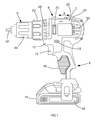
Figure 1 is a side view of a drill/driver; -
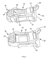
Figure 2 is a side view of two removeably mountable resiliently deformable covers made from black rubber; -
Figure 3 is a side view of an alternative design of two removeably mountable resiliently deformable covers made from white rubber with a black pattern and advertising; -
Figures 4A and 4B are top and side views respectively of a drill/driver with a third design of a removeably mountable resiliently deformable cover made from black rubber with a white advertisement; and -
Figures 5A and 5B are top and side views respectively of a drill/driver with a fourth design of a removeably mountable resiliently deformable cover made from black rubber with a white advertisement. - Referring to
Figure 1 , a drill/driver comprises ahousing 2 formed from a number of hard plastic yellow clam shells which are attached to each other by a number of screws (not shown). The housing comprises a generally horizontal tubulartop section 4 in which is located an electric motor (not shown) and a gear set (not shown), and a generally verticaltubular section 6 which connects to the underside of thehorizontal section 4. The generallyvertical section 6 is shaped to accommodate a hand of an operator in order to form ahandle 16 by which an operator can support the drill/driver. The verticaltubular section 6 and the rear of the horizontal tubular section is covered in an over mold, made from black rubber material, which is non removeably attached to the hard plastic clam shells. Formed in the side of thehousing 2 in the horizontal tubulartop section 4 is arecess 40 in which is located, in a fixed manner, a label on which the brand name of the manufacturer and the name of the particular product is printed. DEWALT ® and XR ® are registered trade marks of The Black & Decker Corporation. Arectangular rubber buffer 70 is attached to and protrudes from thehousing 2 adjacent therecess 40. - Attached to an output spindle of the gear set which projects from a forward end of the
horizontal section 4, is achuck 8 which is capable of supporting a cutting tool such as a drill bit. The chuck comprisessilver jaws 42 for holding the cutting tool and a black rotatableplastic sleeve 44 for adjusting the position of the jaws in well known manner. Thehousing 2 further comprises aswitch housing 10 in which is mounted an electric switch (not shown) which can be activated by depression of ablack plastic button 12 connected to the electric switch and which is slideably mounted within an aperture form in the wall of thehousing 2. - A
battery pack 14 is releaseably attached to a socket formed within the lower end of thevertical section 6. Thebattery pack 14, when located within the socket, is in electrical connection with the switch via a first set of electric wires (not shown) located inside of thevertical section 6, the switch being in electrical connection with the motor via a second set of electric wires (not shown). Depression of thebutton 12 provides an electrical connection between the battery and the motor, activating the motor, causing it to rotate. The housing of thebattery pack 14 is made from black plastic. Formed in the side of the housing of thebattery pack 14 is arecess 46 in which is located, in a fixed manner, a label on which the name of the particular type of battery is printed. - A black
plastic slider 18 is mounted adjacent thebutton 12 within a second aperture formed through the wall of the housing which can be axially slid between two positions. Theslider 18 is connected to the electric switch. When theslider 18 is in its first position, depression of thebutton 12 causes the motor to rotate in a first forward direction. When the slider is in its second position, depression of the button causes the motor to rotate in a second reverse direction. Use of theslider 18 enables the operator to alter the direction of rotation of thechuck 8 by the motor. - When the motor is activated, the drive spindle of the motor rotationally drives the gears within the gear set, which in turn rotationally drives the output spindle of the gear set, which in turn rotationally drives the
chuck 8. The rotational speed of the drive spindle of the motor is reduced by the gear set so that the rotational speed of the output spindle is less than that of the drive spindle. The amount by which the speed is reduced can be adjusted between two different speed settings. Located within a third aperture formed through a top wall of thehousing 2 is a blackplastic sliding switch 20. The slidingswitch 20 connects to the gear set. Theswitch 20 can be slid in a forward and reverse manner (Arrow A) within the aperture between two positions, each position resulting in the gear set reducing the rotational speed of the motor by a different amount. - The gear set also comprises an adjustable torque clutch (not shown) by which rotational movement of the drive spindle is transferred to the output spindle. When an excessive torque is place on the out put spindle, the torque clutch is able to slip, allowing the drive spindle of the motor to continue rotating whilst the output spindle remains stationary, thus preventing damage to motor and prevent an unwanted twisting movement of the
housing 2 due to kick back. The torque setting of the clutch can be adjusted using a blackplastic collar 22 rotationally mounted on the forward end of thehorizontal section 4 of the housing. Rotational movement of thecollar 22 adjusts the torque setting. A series ofnumbers 48, printed in yellow, indicated the torque setting of thecollar 22. - When the motor is activated, it generates a large amount of heat. Therefore a fan (not shown) is mounted on the drive spindle of the motor. As the drive spindle rotates, the fan rotates drawing air over the motor.
Vents 50 are formed through the rear end of thehorizontal section 4 through which the hot air is expelled from the inside of thehousing 2. - The use of the yellow and black livery on the external surfaces of the drill/driver, provide a distinctive appearance.
-
Figure 2 shows a side view of two removeably mountable resilientlydeformable covers 52 made from black rubber and forms the first embodiment of the invention. The resilient deformable cover is a blank advertising wrap which can utilized as an advertising wrap for the drill/driver. The resiliently deformable cover is capable of being releasably mounted onto a part thehorizontal section 4 of the housing of drill driver.Figures 4A and 4B show a second design (which forms a second embodiment of the present invention) of a removeably mountable resiliently deformable cover mounted on a drill/driver. - Referring back to
Figure 2 , the resilientlydeformable cover 52 is made from a resilient material such as rubber. The resilientlydeformable cover 52 is manufactured in a one piece construction and comprises atubular body section 54 with oneend 56 sealed by an end cap. A series ofapertures cover 52. - When the
cover 52 is located on the drill driver (two examples of alternative designs of cover are shown inFigures 4A, 4B ,5A and 5B mounted on drill/drivers):- - the
first aperture 58 is dimensioned and positioned on the cover so that it locates over therecess 40 formed in thehousing 2 of the drill/driver and exposes it so that the label within it remains visible when the cover is located on thehousing 4 of the drill driver. It will be appreciated however that the cover could be utilised to conceal a label attached to a drill/driver. - the
second aperture 60 is dimensioned and positioned on thecover 52 so that it locates around the black plastic slidingswitch 20 of the drill/driver and allows it to be slid freely between its two positions by an operator. - the
third aperture 62 is dimensioned and positioned on thecover 52 so that thevertical section 6 of the drill/driver can extend through it. - the
fourth aperture 64 is dimensioned and positioned on the cover so that it locates over the air vents 50 formed in thehousing 2 of the drill/driver, leaving them fully exposed (and therefore visible) so that thecover 52 does not interfere with the air passing through thevents 50 and therefore operation of the drill/driver which would result in it over heating. - the
fifth aperture 66 is dimensioned and positioned on thecover 52 so that the front part of thehorizontal section 4 of the drill/driver can extend through it and allow the chuck to locate forward of thecover 52. Astrap 68, which forms the lower edge of thefifth aperture 66 wraps around theswitch housing 10 of the drill driver. - The internal shape of the
cover 52 is formed so that it is similar to or corresponds directly with the external shape of the part of the drill/driver on which it is mounted, with dimensions slightly smaller so that it remains in a slightly stretched condition when located on the drill/driver. This provides frictional engagement between the cover and the housing of the drill/driver which ensures that the resilient nature of thecover 52 is utilized to secure the cover to the drill/driver and to allow the drill/driver to be used with the cover attached. - The external shape of the
cover 52 can mirror the internal shape, so that features of the external shape of the drill/driver are replicated on the cover. The internal shape of thecover 52 provides a rectangular recess for accommodating therubber buffer 70 on the drill driver. As shown inFigure 2 , the external shape of thecover 52 mirrors this and provides arectangular projection 72 which locates adjacent to therecess 40 and protects from the side of thecover 52. The resilient nature of thecover 52 improves the performance of therubber buffer 70 of the drill/driver. - Alternatively, the external shape of the
cover 52 can be different to that of the internal shape, so that the addition of the cover to the drill/driver provides an overall alternative shape. - In order to locate the
cover 52 onto the drill/driver, thechuck 8 and the front part of the horizontal section are first passed through thethird aperture 62 and then through thefifth aperture 66, the cover stretching as it does so. Thestrap 68 wraps around theswitch housing 10. Then theend cap 56 is wrapped around the rear part of the horizontal section of the drill/driver, by stretching the cover over the housing, and encloses it. The apertures formed through the cover locate adjacent their corresponding features on the drill/driver. The cover remains slightly stretched once located on the drill/driver to secure it in place. To remove the cover, theend cap 56 is removed from the rear part of the horizontal section by stretching it over the rear part. Thechuck 8 and the front part of the horizontal section are then passed through thefifth aperture 6 and through thethird aperture 62. - In order use the cover as an advertising wrap, logos and/or information, such as text can be added to the external surface of the cover, thus enabling additional information or advertisements to be added to the drill/driver for the operator's benefit.
Figure 3 shows such covers with a logo added. TECH3 is a trade mark owned by Tech3 Sarl. - The cover also damps the amount of noise emitted by the operation of the drill/driver.
- Referring to
Figure 3 , an alternative design (third embodiment) is shown. Where the same features as the first embodiment are shown, the same reference numbers are used. The main different between this embodiment and the first is that the cover is a white colour with a black pattern, and the fact that it has a logo located upon. This enables part of the colour of the livery of a drill/driver to be altered and that additional logos to be added to the drill/driver after the completion of the manufacture of the drill/driver. In addition, or alternatively, text, for example, safety information or operating instructions can be located on the cover enabling this addition text to be added to the product after it has been manufactured (for example to make the drill/driver compliant with new safety legislation which came into force after the manufacture of the drill/driver). The colour of the cover, the logos and text can be integrally molded into the cover, or printed externally onto the cover. The addition of a cover with logos and/or text enables the cover to act as an advertising wrap. - Referring to
Figures 4 and5 , alternative designs (third and fourth embodiments) ofcover 52 are shown. Where the same features as the first embodiment are shown, the same reference numbers are used. The main different between this embodiment and the first is that the cover has a logo located upon and has the apertures which, in part, are of a different shape and in different locations.
Claims (14)
- An advertising wrap for a power tool having a housing with an outer surface, the advertising wrap comprising a cover (52) which is manufactured from a resilient deformable material and is capable of being removeably mounted on a part of an outer surface of a housing of a power tool, the cover comprising at least two apertures (62, 66) through each of which at least a part of the housing of a power tool is capable of projecting when the cover is mounted on a power tool, the cover being in a stretched state when mounted on a power tool to cause it to frictionally engage with an outer surface of the housing in order to retain it on the power tool.
- An advertising wrap according to claim 1 wherein the cover comprises at least one additional aperture (58, 60, 64) which, when the cover is mounted on a part of a housing of power tool, is capable of aligning with a predetermined area of the outer surface of the part of the housing.
- An advertising wrap according to any one of claims 1 or 2 wherein the internal shape of the cover comprises a similar shape to the outer surface of the part of a housing of a power tool on which it is intended to be mounted.
- An advertising wrap according to any one of claims 1 to 3 wherein the external shape of the cover mirror that of an outer surface of a part of a housing of a power tool on which it is intended to be mounted.
- An advertising wrap according to any one of claims 1 to 3 wherein the external shape of the cover is different to an outer surface of a part of a housing of a power tool on which it is intended to be mounted.
- An advertising wrap according to any one of claims 1 to 5 wherein the dimensions of the internal surface of the cover are smaller than those of an outer surface of a part of a housing of a power tool on which it is intended to be mounted to cause the cover to be stretched when it is mounted on that part of the housing.
- An advertising wrap according to any one of claims 1 to 6 wherein logos and/or information is attached to the outer surface of the cover.
- An advertising wrap according to claim 7 wherein the logos and/or information are integrally formed as part of the cover.
- An advertising wrap according to either of claims 7 or 8 wherein the logos and/or information are printed onto the external surface of the cover.
- An advertising wrap according to any one of claims 1 to 9 wherein the cover is manufactured in a one piece construction.
- An advertising system for a power tool comprising an advertising wrap in accordance with any one of claims 1 to 10 and a power tool, the power tool comprising a housing having an outer surface, the advertising wrap comprising a cover (52) which is manufactured from a resilient deformable material and is capable of being removeably mounted on a part of the outer surface of the housing, the cover comprising at least two apertures (62, 66) through each of which at least a part of the housing of a power tool projects, the cover being in a stretched state when mounted an the part of the housing causing it to frictionally engage with the outer surface of the housing in order to retain it on the part of the housing.
- An advertising system according to claim 11 wherein the cover comprises at least one additional aperture (58, 60, 64) which, when the cover is mounted on the part of the housing, aligns with a predetermined area of the outer surface of the part of the housing, wherein the predetermined area comprises an aperture (50) formed through the wall of the housing and/or an actuator (20) and/or an area (40) comprising a logo or information attached to outer surface of the housing.
- An advertising system according to either of claims 11 or 12 wherein the colour of the cover is different to that of the outer surface of the housing.
- An advertising system according to any one of claims 11 to 13 wherein the power tool is a drill/driver and the cover comprises a tubular body and an end cap.
Applications Claiming Priority (1)
| Application Number | Priority Date | Filing Date | Title |
|---|---|---|---|
| GBGB1300211.8A GB201300211D0 (en) | 2013-01-07 | 2013-01-07 | Advertising wrap |
Publications (2)
| Publication Number | Publication Date |
|---|---|
| EP2752838A2 true EP2752838A2 (en) | 2014-07-09 |
| EP2752838A3 EP2752838A3 (en) | 2014-08-13 |
Family
ID=47748043
Family Applications (1)
| Application Number | Title | Priority Date | Filing Date |
|---|---|---|---|
| EP14150155.1A Withdrawn EP2752838A3 (en) | 2013-01-07 | 2014-01-03 | Advertising wrap |
Country Status (3)
| Country | Link |
|---|---|
| US (1) | US20140190717A1 (en) |
| EP (1) | EP2752838A3 (en) |
| GB (1) | GB201300211D0 (en) |
Families Citing this family (12)
| Publication number | Priority date | Publication date | Assignee | Title |
|---|---|---|---|---|
| JP6032400B2 (en) * | 2012-08-15 | 2016-11-30 | 日立工機株式会社 | Chainsaw |
| WO2020252350A1 (en) * | 2019-06-12 | 2020-12-17 | Milwaukee Electric Tool Corporation | Rotary power tool |
| US11865679B2 (en) | 2019-10-11 | 2024-01-09 | Ingersoll-Rand Industrial U.S., Inc. | Battery powered impact wrench |
| US12059775B2 (en) | 2019-12-19 | 2024-08-13 | Black & Decker Inc. | Power tool with compact motor assembly |
| US11509193B2 (en) | 2019-12-19 | 2022-11-22 | Black & Decker Inc. | Power tool with compact motor assembly |
| US11705778B2 (en) | 2019-12-19 | 2023-07-18 | Black & Decker Inc. | Power tool with compact motor assembly |
| JP1690815S (en) * | 2020-02-07 | 2021-07-26 | ||
| JP1690816S (en) * | 2020-02-07 | 2021-07-26 | ||
| JP1682378S (en) | 2020-02-07 | 2021-04-05 | ||
| US11213847B1 (en) | 2020-10-27 | 2022-01-04 | Chris Olsen | Cover for spray a gun |
| US12233523B2 (en) * | 2020-12-07 | 2025-02-25 | Black & Decker Inc. | Power tool with multiple modes of operation and ergonomic handgrip |
| DE202021103316U1 (en) | 2021-06-21 | 2021-06-28 | E. Zoller GmbH & Co. KG Einstell- und Messgeräte | Tool identification chip |
Citations (1)
| Publication number | Priority date | Publication date | Assignee | Title |
|---|---|---|---|---|
| KR20120083014A (en) * | 2011-01-17 | 2012-07-25 | 계양전기 주식회사 | Protective cap for ventilation path guided power tools |
Family Cites Families (19)
| Publication number | Priority date | Publication date | Assignee | Title |
|---|---|---|---|---|
| US2207269A (en) * | 1938-11-16 | 1940-07-09 | Henry T Schiff | Nonslip shaving implement |
| US4879847A (en) * | 1989-03-13 | 1989-11-14 | Snap-On Tools Corporation | Cover for pneumatic tool |
| US4981247A (en) * | 1989-07-17 | 1991-01-01 | Richard C. Noll | Protective cover for an electric stapler |
| US5006740A (en) * | 1990-06-13 | 1991-04-09 | Milwaukee Electric Tool Corporation | Insulated cooling boot for power tool |
| US5302124A (en) * | 1993-03-25 | 1994-04-12 | Pinnacle Products, Inc. | Disposable protective sleeve for dental apparatus such as light curing guns |
| JP2000167784A (en) * | 1998-12-03 | 2000-06-20 | Makita Corp | Power tool |
| US6199383B1 (en) * | 1999-02-11 | 2001-03-13 | Snap-On Tools Company | Pneumatic tool and air deflector boot therefor |
| CN1305013C (en) * | 2002-11-28 | 2007-03-14 | 日立工机株式会社 | Portable tool having cover and label to be stuck on the portable tool for identification |
| US20050257944A1 (en) * | 2004-05-20 | 2005-11-24 | Cooper Vincent P | Handle assembly for tool |
| US6860342B1 (en) * | 2004-06-07 | 2005-03-01 | Techway Industrial Co., Ltd. | Tool housing with protective pads |
| US20060236522A1 (en) * | 2004-12-22 | 2006-10-26 | Lin Hung W | Method for manufacturing tool handle |
| JP4456499B2 (en) * | 2005-02-10 | 2010-04-28 | 株式会社マキタ | Work tools |
| BRPI0504616A (en) * | 2005-06-08 | 2006-04-11 | Embraer Aeronautica Sa | anti-vibration coating of aircraft pneumatic hammers handles |
| USD590226S1 (en) * | 2006-05-22 | 2009-04-14 | Fairskq (Taiwan) Co., Ltd | Air impact wrench |
| USD540640S1 (en) * | 2006-06-22 | 2007-04-17 | Chicago Pneumatic Tool Company | Impact wrench |
| US7341173B1 (en) * | 2006-10-05 | 2008-03-11 | Arnold John L | Exhaust gas diffuser and filter system for a pneumatic nail gun |
| USD610888S1 (en) * | 2008-09-11 | 2010-03-02 | Kabushiki Kaisha Shinano Seisakusho | Impact wrench |
| US8267192B2 (en) * | 2009-02-24 | 2012-09-18 | Black & Decker Inc. | Ergonomic handle for power tool |
| USD617622S1 (en) * | 2009-09-30 | 2010-06-15 | Black & Decker Inc. | Impact driver |
-
2013
- 2013-01-07 GB GBGB1300211.8A patent/GB201300211D0/en not_active Ceased
-
2014
- 2014-01-03 EP EP14150155.1A patent/EP2752838A3/en not_active Withdrawn
- 2014-01-06 US US14/147,695 patent/US20140190717A1/en not_active Abandoned
Patent Citations (1)
| Publication number | Priority date | Publication date | Assignee | Title |
|---|---|---|---|---|
| KR20120083014A (en) * | 2011-01-17 | 2012-07-25 | 계양전기 주식회사 | Protective cap for ventilation path guided power tools |
Also Published As
| Publication number | Publication date |
|---|---|
| GB201300211D0 (en) | 2013-02-20 |
| EP2752838A3 (en) | 2014-08-13 |
| US20140190717A1 (en) | 2014-07-10 |
Similar Documents
| Publication | Publication Date | Title |
|---|---|---|
| US20140190717A1 (en) | Resilient Cover For Power Tool | |
| US10478950B2 (en) | Power tool | |
| US20250144773A1 (en) | Impact tool | |
| US10040178B2 (en) | Power tool and rotary impact tool | |
| CN204748551U (en) | Electric tool | |
| EP2602066B1 (en) | Electric power tool | |
| EP2338645A2 (en) | Power tool | |
| US10660624B2 (en) | Surgical handpiece having direction-shifting function | |
| US20150209951A1 (en) | Handheld Power Tool | |
| JP2016153153A (en) | Electric tool with vibration mechanism | |
| JP7263469B2 (en) | impact tool | |
| CN101687318A (en) | Electric tool | |
| JP6812111B2 (en) | Rotating tool | |
| JP2009083058A (en) | Electric tool | |
| EP4067007B1 (en) | Hand-held power tool having a tool housing with an elongated light emitting device | |
| JP6863415B2 (en) | Electric tool | |
| JP6036320B2 (en) | Portable work machine | |
| JP2017144523A5 (en) | ||
| JP6723833B2 (en) | Electric tool | |
| JP2017136666A (en) | Power tool | |
| AU2015205895B2 (en) | A range of power tools | |
| JP4998079B2 (en) | Electric tool | |
| JP4789617B2 (en) | Electric tool | |
| CN104339327A (en) | Electric tool and electric shears accessory thereof | |
| JP2020196052A (en) | Electric tool |
Legal Events
| Date | Code | Title | Description |
|---|---|---|---|
| 17P | Request for examination filed |
Effective date: 20140103 |
|
| AK | Designated contracting states |
Kind code of ref document: A2 Designated state(s): AL AT BE BG CH CY CZ DE DK EE ES FI FR GB GR HR HU IE IS IT LI LT LU LV MC MK MT NL NO PL PT RO RS SE SI SK SM TR |
|
| AX | Request for extension of the european patent |
Extension state: BA ME |
|
| PUAI | Public reference made under article 153(3) epc to a published international application that has entered the european phase |
Free format text: ORIGINAL CODE: 0009012 |
|
| PUAL | Search report despatched |
Free format text: ORIGINAL CODE: 0009013 |
|
| AK | Designated contracting states |
Kind code of ref document: A3 Designated state(s): AL AT BE BG CH CY CZ DE DK EE ES FI FR GB GR HR HU IE IS IT LI LT LU LV MC MK MT NL NO PL PT RO RS SE SI SK SM TR |
|
| AX | Request for extension of the european patent |
Extension state: BA ME |
|
| RIC1 | Information provided on ipc code assigned before grant |
Ipc: G09F 23/00 20060101AFI20140710BHEP |
|
| R17P | Request for examination filed (corrected) |
Effective date: 20150113 |
|
| RBV | Designated contracting states (corrected) |
Designated state(s): AL AT BE BG CH CY CZ DE DK EE ES FI FR GB GR HR HU IE IS IT LI LT LU LV MC MK MT NL NO PL PT RO RS SE SI SK SM TR |
|
| 17Q | First examination report despatched |
Effective date: 20160225 |
|
| STAA | Information on the status of an ep patent application or granted ep patent |
Free format text: STATUS: THE APPLICATION IS DEEMED TO BE WITHDRAWN |
|
| 18D | Application deemed to be withdrawn |
Effective date: 20160907 |