EP2752780A1 - Simulation model generation method for filler mixed material - Google Patents
Simulation model generation method for filler mixed material Download PDFInfo
- Publication number
- EP2752780A1 EP2752780A1 EP20120840968 EP12840968A EP2752780A1 EP 2752780 A1 EP2752780 A1 EP 2752780A1 EP 20120840968 EP20120840968 EP 20120840968 EP 12840968 A EP12840968 A EP 12840968A EP 2752780 A1 EP2752780 A1 EP 2752780A1
- Authority
- EP
- European Patent Office
- Prior art keywords
- filler
- model
- elements
- simulation
- interface
- Prior art date
- Legal status (The legal status is an assumption and is not a legal conclusion. Google has not performed a legal analysis and makes no representation as to the accuracy of the status listed.)
- Granted
Links
Images



Classifications
-
- G—PHYSICS
- G06—COMPUTING OR CALCULATING; COUNTING
- G06F—ELECTRIC DIGITAL DATA PROCESSING
- G06F30/00—Computer-aided design [CAD]
- G06F30/20—Design optimisation, verification or simulation
- G06F30/23—Design optimisation, verification or simulation using finite element methods [FEM] or finite difference methods [FDM]
-
- G—PHYSICS
- G06—COMPUTING OR CALCULATING; COUNTING
- G06F—ELECTRIC DIGITAL DATA PROCESSING
- G06F30/00—Computer-aided design [CAD]
- G06F30/20—Design optimisation, verification or simulation
-
- G—PHYSICS
- G06—COMPUTING OR CALCULATING; COUNTING
- G06F—ELECTRIC DIGITAL DATA PROCESSING
- G06F2111/00—Details relating to CAD techniques
- G06F2111/10—Numerical modelling
Definitions
- the present invention relates to a method for producing a simulation model of a filler compound readily and in a short time using a computer.
- the filler compound includes a filler dispersed and mixed in a matrix.
- the simulation model “a” typically includes filler model s "b” representing the filler, interface models “c” having a small thickness and arranged outside the filler models "b”, and matrix models “d” arranged outside the interface models "c” and representing the matrix.
- Patent document 1 includes the following steps s1 to s6 to automatically produce the simulation model "a".
- Patent document 1 Japanese Patent No. 4695399 .
- the outline shape of the filler is not only a single particle having a simple spherical shape, but also, as shown in FIG. 8 , a plurality of connected particles having a complicated shape of a bunch of grapes. Consequently, concerning the filler "f" having the complicated shape, for example, as shown in FIG. 9 , which illustrates the state after the step s3, and FIG. 10 , which is an enlarged view of the part A of FIG.
- the present invention has been made in vi ew of the above problems. It is a main object of the present invention to provide a method for producing a simulation model of a filler compound readily and in a short time.
- the method basically includes: determining a boundary to partition a simulation-model forming space into a filler region and a non-filler region; dividing the filler region into a finite number of el ements so as to set a filler model; dividing the non-filler region into a finite number of elements; setting, as an interface model, elements at least in contact with the filler model among the elements of the non-filler region; and setting, as a matrix element, elements outside the interface model among the elements of the non-filler region.
- the present invention provides for a method for producing, using a computer, a simulation model of a filler compound in which a filler is dispersed and mixed in a matrix, the method comprising: partitioning an simulation-model forming space into a filler region and a non-filler region so as to determine a boundary between these regions; dividing the filler region into a finite number of elements so as to set a filler model ; dividing the non-filler region into a finite number of elements; setting, as an interface model , at least one element among the elements of the non-filler region, the at least one element being at least in contact with the filler model; and setting, as a matrix model , at least one element among the elements of the non-filler region, the at least one element being outside the interface model.
- the step of setting the interface model may comprise setting, as the interface model, the elements in contact wi th the filler model and el ements in contact wi th an outsi de of the elements in contact with the filler model.
- physical property different from a physical property of the matrix model may be defined for the interface model.
- the method for producing the simulation model of the filler compound includes partitioning an simulation-model forming space into a filler region and a non-filler region so as to determine a boundary between these regions, dividing the filler region into a finite number of elements so as to set a filler model, dividing the non-filler region into a finite number of elements, setting, as an interface model, at least one element among the elements of the non-filler region, the at least one element being at least in contact with the filler model, and setting, as a matrix model , at least one element among the elements of the non-filler region, the at least one element being outside the interface model.
- carbon reinforced rubber in which carbon is dispersed and mixed in rubber is suggested as a filler compound, and a procedure for producing a two-dimensional (single-plane) simulation model of the carbon reinforced rubber is described. This procedure is conducted using a computer device, not shown.
- FIG. 1 shows an example of the processing procedure of a method for producing the simulation model according to the embodiment of the present invention.
- a simulation-model forming space is first partitioned into a filler region and a non-filler region, and a boundary of these regions are set (step S1).
- FIG. 2 shows a rectangul ar two-di mensi onal space "j", whi ch has a predetermined size as the simulation-model forming space.
- the two-dimensional space "j" constitutes a microstructure (also referred to as a unit cell) as a minimum unit of the simulation model.
- This two-dimensional space "j" is partitioned into a plurality of filler regions 2 and a non-filler region 3. Thus, boundaries E are set to partition these regions 2 and 3.
- any of the four filler regions 2a to 2d is a closed space.
- the non-filler region 3 is specified as an outside area of the boundaries Ea to Ed in the two-dimensional space "j".
- Such boundaries Ea to Ed may be obtained using any method.
- a microscopic image of an actual filler compound is subjected to conventionally known image processing, so as to obtain the boundaries Ea to Ed.
- a microscopic image containing matrix rubber and carbon is obtained using, for example, a TEM, and this image is processed into raster data (note that this processing is unnecessary when digital data can be directly obtained).
- noise is removed.
- This rasterized image can be subjected to processing to extract the edges of the filler. These extracted edges correspond to the boundaries Ea to Ed.
- the edges are continuous, discontinuous portions of the edges are preferably subjected to processing such as interpolation processing to make the discontinuous portions continuous.
- each of the filler regions 2a to 2d is divided into a finite number of elements 4a so as to set a filler model 4.
- the non-filler region 3 is divided into a fi ni te number of el ements 5a (steps S2 and S3). Either of these steps may be performed first.
- the filler regions 2a to 2d, each of which is a closed space, and the non-filler region 3 are respectively divided into the finite numbers of small elements 4a and 5a (that is, mesh processing) using various types of application software.
- the shape of the elements 4a and 5a is preferably a triangle or a rectangle in the case of plane elements. Also, concerning the size of the elements 4a and 5a, a preferable range is determined in advance in accordance with, for example, an object of analysis, so that the processing can be performed in accordance with the preferable range.
- Information such as node coordinates, element numbers, elements shapes of all the elements 4a and 5a after divided is stored in the computer device.
- setting the filler model 4" means adding information by which the elements 4a corresponding to the filler model 4 among the elements stored in the computer can be discriminated as the el ements consti tuti ng the filler model 4, so that the el ements 4a can be discriminated from other elements.
- processing is performed to set, as an interface model 6, elements 6a in contact with the filler model 4 among the el ements 5a of the non-filler region 3 (step S4).
- the node coordinates of all the elements are stored in the computer, and also, among all the elements, the elements constituting the filler model 4 can be discriminated. Therefore, based on the information, the computer is able to quickly extract the elements in contact with the filler model 4 and to set these elements as the interface model 6.
- the elements 6a in contact with the filler model 4" are the elements that have sides and nodes in common with the elements 4a constituting the filler model 4. Further, in this embodiment, since the filler model 4 has the continuous edges (the outline) surrounding the closed space, the elements 4a in contact with the edges, that is, the interface model, is annularly continuous.
- setting as the interface model 6 means adding information by which the elements corresponding to the interface model 6 among the elements stored in the computer can be discriminated as the elements constituting the interface model 6, so that the elements corresponding to the interface model 6 can be discriminated from other elements.
- processing is performed to set, as a matrix model 7, elements 7a outside the interface model 6 among the elements of the non-filler region 3 (step S5).
- This processing results in production of the simulation model 10, as shown in FIG. 6 , in which the two-dimensional space "j" is partitioned into the filler models 4, the matrix model 7, and the interface models 6 between the filler models 4 and the matrix model 7.
- each of the elements 6a of the interface model 6, and each of the elements 7a of the matrix model 7 values of physical properties such as density and modulus of elasticity are defined as computing parameters, and stored in the computer device.
- physical properties different from physical properties of the matrix model 7, for example, a larger hardness and a larger tan ⁇ than the matrix model 7, are preferably defined.
- the simulation model 10 produced through the above-descri bed processing has an outline shape and a dispersed state closely resembling an outline shape and a dispersed state of actual carbon. Consequently, calculation results in the simulation approximate calculation results of the actual material, so that a significant improvement in simulation precision can be expected. Also, even if the filler has a complicated outline shape including, for example, re-entrant parts, the producing processing of the simulation model 10 can be performed by continuous automatic processing with the computer. This reduces the number of human operations and the producing processing can be performed in a short time.
- the two-dimensional simulation model 10 has been described. Another possible example is to repeatedly perform the above-described processing in the di recti on of thickness of the carbon reinforced rubber and to produce a three-dimensional simulation model between the repetitions.
- the thickness of the interface model 6 is generally considered to be approximately one to ten nanometers.
- the thickness of the interface model 6 can be set as desired in accordance with the size of the elements a.
- the elements 6a in contact with the filler model 4, and elements 6b in contact with an outside of the elements 6a can be further set as the interface model 6.
- the number of the elements in contact with the outside of the elements 6a can be determined to change the thickness.
- the thickness of the interface model 6 can be set to be large and as desi red in accordance wi th the size of the elements.
- the present invention can be likewise applied to production of a simulation model of, for example, rubber compositions and various types of elastomers including silica as a filler.
Landscapes
- Engineering & Computer Science (AREA)
- Physics & Mathematics (AREA)
- Theoretical Computer Science (AREA)
- Computer Hardware Design (AREA)
- Evolutionary Computation (AREA)
- Geometry (AREA)
- General Engineering & Computer Science (AREA)
- General Physics & Mathematics (AREA)
- Management, Administration, Business Operations System, And Electronic Commerce (AREA)
- Processes Of Treating Macromolecular Substances (AREA)
Abstract
Description
- The present invention relates to a method for producing a simulation model of a filler compound readily and in a short time using a computer. The filler compound includes a filler dispersed and mixed in a matrix.
- Recently, analysis by computer simulation has been conducted to evaluate, for example, deformation behaviors, stresses, and strain distribution states of a filler compound (for example, carbon reinforced rubber) in which a filler (for example, carbon black) is dispersed and mixed in a matrix (for example, rubber). In order to conduct the computer simulation, it is required to prepare a simulation model of the above filler compound that can be used in a numerical analysis method such as the finite element method.
- An example of such a simulation model, "a", is visualized i n
FIG. 8 . The simulation model "a" typically includes filler model s "b" representing the filler, interface models "c" having a small thickness and arranged outside the filler models "b", and matrix models "d" arranged outside the interface models "c" and representing the matrix. - In an actual materi al , physical layers such as the interface models "c" may not be identified distinctly. However, it has been known that portions of the matrix that are in contact wi th the filler show different values of physical properties as compared with other different portions of the matrix. Based on this knowledge, the interface models "c" are often employed.
- The applicant of the present invention has already suggested Patent document 1, specified below, as a method for producing a simulation model "a" using a computer. Patent document 1 includes the following steps s1 to s6 to automatically produce the simulation model "a".
- s1) A step of obtaining an image containing a matrix and a filler from a filler compound.
- s2) A step of extracti ng the edges of the filler from the image.
- s3) A step of setting the outlines offset for a predetermined thickness outside the edges after extracting the edges.
- s4) A step of di vi di ng an inside area of the edges into el ements and defining an aggregate of the elements as a filler model.
- s5) A step of dividing an outside area of the outlines into elements and defining an aggregate of the elements as a matrix model.
- s6) A step of dividing an area between the outlines and the edges into elements and defining an aggregate of the elements as an interface model having values of physical properties different from values of physical properties of the matrix model.
- Patent document 1: Japanese Patent No.
4695399 - Unfortunately, the above method involves the following problems. The outline shape of the filler is not only a single particle having a simple spherical shape, but also, as shown in
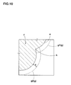
FIG. 8 , a plurality of connected particles having a complicated shape of a bunch of grapes. Consequently, concerning the filler "f" having the complicated shape, for example, as shown inFIG. 9 , which illustrates the state after the step s3, andFIG. 10 , which is an enlarged view of the part A ofFIG. 9 , when the outlines g1 and g2 are set to be offset outside the edge "e" of the filler "f" for a predetermined thickness z, there are cases in which the outlines g1 and g2 intersect each other in a re-entrant part k of the edge "e" in particular. Such a phenomenon makes it difficult to perform steps s4 and s6 using the computer, such that the processing may be interrupted. In this case, it is required to manually correct the outlines g1 and g2 of the interface model. Thus, unfortunately, operations for producing the simulation model require a long time. - The present invention has been made in vi ew of the above problems. It is a main object of the present invention to provide a method for producing a simulation model of a filler compound readily and in a short time. The method basically includes: determining a boundary to partition a simulation-model forming space into a filler region and a non-filler region; dividing the filler region into a finite number of el ements so as to set a filler model; dividing the non-filler region into a finite number of elements; setting, as an interface model, elements at least in contact with the filler model among the elements of the non-filler region; and setting, as a matrix element, elements outside the interface model among the elements of the non-filler region.
- The present invention provides for a method for producing, using a computer, a simulation model of a filler compound in which a filler is dispersed and mixed in a matrix, the method comprising: partitioning an simulation-model forming space into a filler region and a non-filler region so as to determine a boundary between these regions; dividing the filler region into a finite number of elements so as to set a filler model ; dividing the non-filler region into a finite number of elements; setting, as an interface model , at least one element among the elements of the non-filler region, the at least one element being at least in contact with the filler model; and setting, as a matrix model , at least one element among the elements of the non-filler region, the at least one element being outside the interface model.
- Preferably, the step of setting the interface model may comprise setting, as the interface model, the elements in contact wi th the filler model and el ements in contact wi th an outsi de of the elements in contact with the filler model.
- Preferably, physical property different from a physical property of the matrix model may be defined for the interface model.
- The method for producing the simulation model of the filler compound includes partitioning an simulation-model forming space into a filler region and a non-filler region so as to determine a boundary between these regions, dividing the filler region into a finite number of elements so as to set a filler model, dividing the non-filler region into a finite number of elements, setting, as an interface model, at least one element among the elements of the non-filler region, the at least one element being at least in contact with the filler model, and setting, as a matrix model , at least one element among the elements of the non-filler region, the at least one element being outside the interface model. Consequently, in setting the interface model , all that is done using the computer is to simply extract only the elements in contact with the filler model among the elements of the non-filler region. This facilitates the setting of the interface model. Note that the thickness of the interface model can be set as desired.
-
- [
FIG. 1] FIG. 1 is a flowchart illustrating an embodiment of the present invention. - [
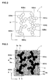
FIG. 2] FIG. 2 is an example of an image in which boundaries to partition a simulation-model forming space into filler regions and a non-filler region are extracted. - [
FIG. 3] FIG. 3 is a diagram illustrating the state in which each of the space ofFIG. 2 is divided into a finite number of elements. - [
FIG. 4] FIG. 4 is a partial enlarged view illustrating a step of setti ng, as an interface model , el ements in contact wi th a filler model. - [
FIG. 5] FIG. 5 is a partial enlarged view illustrating a step of setti ng, as a matrix model , elements outside the interface model. - [
FIG. 6] FIG. 6 is a diagram illustrating a simulation model according to the embodiment of the present invention. - [
FIG. 7] FIG. 7 is a diagram illustrating a simulation model according to another embodiment. - [
FIG. 8] FIG. 8 is a diagram illustrating a conventional simulation model. - [
FIG. 9] FIG. 9 is a di agram illustrating edges and offset outlines of a filler. - [
FIG. 10] FIG. 10 is an enlarged view of a part A ofFIG. 9 . - An embodi ment of the present i nventi on will now be descri bed with reference to the drawings.
- In this embodiment, carbon reinforced rubber in which carbon is dispersed and mixed in rubber is suggested as a filler compound, and a procedure for producing a two-dimensional (single-plane) simulation model of the carbon reinforced rubber is described. This procedure is conducted using a computer device, not shown.
-
FIG. 1 shows an example of the processing procedure of a method for producing the simulation model according to the embodiment of the present invention. In the producing method according to this embodiment, a simulation-model forming space is first partitioned into a filler region and a non-filler region, and a boundary of these regions are set (step S1). -
FIG. 2 shows a rectangul ar two-di mensi onal space "j", whi ch has a predetermined size as the simulation-model forming space. In this embodiment, the two-dimensional space "j" constitutes a microstructure (also referred to as a unit cell) as a minimum unit of the simulation model. This two-dimensional space "j" is partitioned into a plurality offiller regions 2 and anon-filler region 3. Thus, boundaries E are set to partition theseregions - In this embodiment, four
regions 2a to 2d separate from each other are defined for thefiller regions 2. These fourfiller regions 2a to 2d are surrounded by the boundaries (borderlines) Ea to Ed of connected arcs. Thus, any of the fourfiller regions 2a to 2d is a closed space. - The
non-filler region 3 is specified as an outside area of the boundaries Ea to Ed in the two-dimensional space "j". - Such boundaries Ea to Ed may be obtained using any method. Preferably, a microscopic image of an actual filler compound is subjected to conventionally known image processing, so as to obtain the boundaries Ea to Ed. For example, a microscopic image containing matrix rubber and carbon is obtained using, for example, a TEM, and this image is processed into raster data (note that this processing is unnecessary when digital data can be directly obtained). As necessary, noise is removed. This rasterized image can be subjected to processing to extract the edges of the filler. These extracted edges correspond to the boundaries Ea to Ed. It should be noted that unless the edges (the boundaries) are continuous, discontinuous portions of the edges are preferably subjected to processing such as interpolation processing to make the discontinuous portions continuous.
- Next, in this embodiment, as shown in
FIG. 3 , each of thefiller regions 2a to 2d is divided into a finite number ofelements 4a so as to set afiller model 4. Also, thenon-filler region 3 is divided into a fi ni te number of el ements 5a (steps S2 and S3). Either of these steps may be performed first. - The
filler regions 2a to 2d, each of which is a closed space, and thenon-filler region 3 are respectively divided into the finite numbers ofsmall elements elements elements elements - Further, "setting the
filler model 4" means adding information by which theelements 4a corresponding to thefiller model 4 among the elements stored in the computer can be discriminated as the el ements consti tuti ng thefiller model 4, so that the el ements 4a can be discriminated from other elements. - Next, as shown in
FIG. 4 , in this embodiment, processing is performed to set, as aninterface model 6,elements 6a in contact with thefiller model 4 among the el ements 5a of the non-filler region 3 (step S4). The node coordinates of all the elements are stored in the computer, and also, among all the elements, the elements constituting thefiller model 4 can be discriminated. Therefore, based on the information, the computer is able to quickly extract the elements in contact with thefiller model 4 and to set these elements as theinterface model 6. - "The
elements 6a in contact with thefiller model 4" are the elements that have sides and nodes in common with theelements 4a constituting thefiller model 4. Further, in this embodiment, since thefiller model 4 has the continuous edges (the outline) surrounding the closed space, theelements 4a in contact with the edges, that is, the interface model, is annularly continuous. - Moreover, "setting as the
interface model 6" means adding information by which the elements corresponding to theinterface model 6 among the elements stored in the computer can be discriminated as the elements constituting theinterface model 6, so that the elements corresponding to theinterface model 6 can be discriminated from other elements. - Next, as shown in
FIG. 5 , in this embodiment, processing is performed to set, as amatrix model 7,elements 7a outside theinterface model 6 among the elements of the non-filler region 3 (step S5). This processing results in production of thesimulation model 10, as shown inFIG. 6 , in which the two-dimensional space "j" is partitioned into thefiller models 4, thematrix model 7, and theinterface models 6 between thefiller models 4 and thematrix model 7. - Note that, for each of the el ements 4a of the
filler model 4, each of theelements 6a of theinterface model 6, and each of theelements 7a of thematrix model 7, values of physical properties such as density and modulus of elasticity are defined as computing parameters, and stored in the computer device. In particular, for each of theelements 6a constituting theinterface model 6, physical properties different from physical properties of thematrix model 7, for example, a larger hardness and a larger tan δ than thematrix model 7, are preferably defined. Thus, various deformation states that may occur in an actual rubber material, for example, causing a larger energy loss or difficulty in deformation in theinterface model 6, can be reproduced in the simulation with high precision. - The
simulation model 10 produced through the above-descri bed processing has an outline shape and a dispersed state closely resembling an outline shape and a dispersed state of actual carbon. Consequently, calculation results in the simulation approximate calculation results of the actual material, so that a significant improvement in simulation precision can be expected. Also, even if the filler has a complicated outline shape including, for example, re-entrant parts, the producing processing of thesimulation model 10 can be performed by continuous automatic processing with the computer. This reduces the number of human operations and the producing processing can be performed in a short time. - Further, in this embodiment, the two-
dimensional simulation model 10 has been described. Another possible example is to repeatedly perform the above-described processing in the di recti on of thickness of the carbon reinforced rubber and to produce a three-dimensional simulation model between the repetitions. - Moreover, in the case of carbon compound rubber, the thickness of the
interface model 6 is generally considered to be approximately one to ten nanometers. In order to adjust the thickness to such a value, the thickness of theinterface model 6 can be set as desired in accordance with the size of the elements a. For example, in the step S4 of setting theinterface model 6, theelements 6a in contact with thefiller model 4, and elements 6b in contact with an outside of theelements 6a can be further set as theinterface model 6. Then, the number of the elements in contact with the outside of theelements 6a can be determined to change the thickness. Thus, as shown inFIG. 7 , the thickness of theinterface model 6 can be set to be large and as desi red in accordance wi th the size of the elements. - The embodiments of the present invention have been described above. However, other than the carbon reinforced rubber, the present invention can be likewise applied to production of a simulation model of, for example, rubber compositions and various types of elastomers including silica as a filler.
-
- j
- Two-dimensional space of simulation model
- E, Ea to Ed
- Boundary
- 2, 2a to 2d
- Filler region
- 3
- Non-filler region
- 4
- Filler model
- 4a to 4d
- Element constituting filler model
- 6
- model
- 6a to 6d
- Element constituting interface model
- 7
- Matrix model
- 7a to 7d
- Element constituting matrix model
- 10
- Simulation model
Claims (4)
- A method for producing, using a computer, a simulation model of a filler compound in which a filler is dispersed and mixed in a matrix, the method comprising:partitioning an simulation-model forming space into a filler region and a non-filler region so as to determine a boundary between these regions;dividing the filler region into a finite number of elements so as to set a filler model;dividing the non-filler region into a finite number of elements;setting, as an interface model, at least one element among the elements of the non-filler region, the at least one element being at least in contact with the filler model; andsetting, as a matrix model , at least one element among the el ements of the non-filler region, the at least one element being outside the interface model.
- The method for producing the simulation model of the filler compound according to claim 1,
wherein the step of setting the interface model comprises setting, as the interface model, the elements in contact with the filler model and el ements in contact wi th an outsi de of the el ements in contact with the filler model. - The method for producing the simulation model of the filler compound according to claim 1,
wherein the step of setting the interface model comprises setting, as the interface model, at least the elements in contact wi th the filler model and el ements in contact wi th an outsi de of the elements in contact with the filler model. - The method for producing the simulation model of the filler compound according to any of claims 1 to 3,
wherein a physical property different from a physical property of the matrix model is defined for the interface model.
Applications Claiming Priority (2)
| Application Number | Priority Date | Filing Date | Title |
|---|---|---|---|
| JP2011230956A JP5555216B2 (en) | 2011-10-20 | 2011-10-20 | Simulation model generation method for filler compounding materials. |
| PCT/JP2012/076263 WO2013058155A1 (en) | 2011-10-20 | 2012-10-11 | Simulation model generation method for filler mixed material |
Publications (3)
| Publication Number | Publication Date |
|---|---|
| EP2752780A1 true EP2752780A1 (en) | 2014-07-09 |
| EP2752780A4 EP2752780A4 (en) | 2015-06-03 |
| EP2752780B1 EP2752780B1 (en) | 2022-05-04 |
Family
ID=48140803
Family Applications (1)
| Application Number | Title | Priority Date | Filing Date |
|---|---|---|---|
| EP12840968.7A Active EP2752780B1 (en) | 2011-10-20 | 2012-10-11 | Simulation model generation method for filler mixed material |
Country Status (4)
| Country | Link |
|---|---|
| US (1) | US10002210B2 (en) |
| EP (1) | EP2752780B1 (en) |
| JP (1) | JP5555216B2 (en) |
| WO (1) | WO2013058155A1 (en) |
Families Citing this family (4)
| Publication number | Priority date | Publication date | Assignee | Title |
|---|---|---|---|---|
| US10303826B2 (en) | 2013-10-07 | 2019-05-28 | Sumitomo Rubber Industries, Ltd. | Method for creating finite element model for filler-containing rubber |
| JP6492438B2 (en) * | 2014-07-24 | 2019-04-03 | 横浜ゴム株式会社 | Method for creating model for analyzing specific substance, computer program for creating model for analyzing specific substance, simulation method for specific substance, and computer program for simulating specific substance |
| JP6492439B2 (en) * | 2014-07-24 | 2019-04-03 | 横浜ゴム株式会社 | Method for creating model for analyzing specific substance, computer program for creating model for analyzing specific substance, simulation method for specific substance, and computer program for simulating specific substance |
| CN120372751B (en) * | 2025-04-08 | 2025-09-16 | 江西省降龙水利水电建设工程有限公司 | A 3D parametric design method for water conservancy projects based on deep learning |
Family Cites Families (5)
| Publication number | Priority date | Publication date | Assignee | Title |
|---|---|---|---|---|
| JP3668238B2 (en) * | 2003-10-17 | 2005-07-06 | 住友ゴム工業株式会社 | Rubber material simulation method |
| JP4594043B2 (en) * | 2004-11-15 | 2010-12-08 | 住友ゴム工業株式会社 | Rubber material simulation method |
| JP4695399B2 (en) * | 2005-01-11 | 2011-06-08 | 住友ゴム工業株式会社 | Simulation model generation method for filler compounding materials |
| JP4697870B2 (en) * | 2005-10-07 | 2011-06-08 | 住友ゴム工業株式会社 | Simulation method for viscoelastic materials |
| JP4685747B2 (en) * | 2006-11-09 | 2011-05-18 | 住友ゴム工業株式会社 | How to create a rubber material analysis model |
-
2011
- 2011-10-20 JP JP2011230956A patent/JP5555216B2/en active Active
-
2012
- 2012-10-11 US US14/350,319 patent/US10002210B2/en active Active
- 2012-10-11 WO PCT/JP2012/076263 patent/WO2013058155A1/en not_active Ceased
- 2012-10-11 EP EP12840968.7A patent/EP2752780B1/en active Active
Also Published As
| Publication number | Publication date |
|---|---|
| US10002210B2 (en) | 2018-06-19 |
| EP2752780A4 (en) | 2015-06-03 |
| US20140257783A1 (en) | 2014-09-11 |
| JP5555216B2 (en) | 2014-07-23 |
| WO2013058155A1 (en) | 2013-04-25 |
| EP2752780B1 (en) | 2022-05-04 |
| JP2013089124A (en) | 2013-05-13 |
Similar Documents
| Publication | Publication Date | Title |
|---|---|---|
| CN112912884B (en) | Material designing apparatus, material designing method, and material designing program | |
| Hallberg et al. | Modeling of grain growth under fully anisotropic grain boundary energy | |
| DE112020002059T5 (en) | TOPOLOGY OPTIMIZATION OF A MULTI-TARGET STRUCTURE | |
| Li et al. | Quantifying the reduction intensity of handaxes with 3D technology: a pilot study on handaxes in the Danjiangkou Reservoir Region, Central China | |
| EP3768448B1 (en) | Method for determining building regulations for an additive production method, method for creating a database with corrective measures for the management of an additives production process, storage format for building instructions and a computer program product | |
| EP2752780B1 (en) | Simulation model generation method for filler mixed material | |
| CN109414879B (en) | Multiscale Density Threshold Matrix for 3D Printing | |
| CN116205112B (en) | Grain boundary stress concentration factor calculation method, apparatus, medium, and program | |
| DE102012209527A1 (en) | IMMERSIVE MASS DEVIATION | |
| DE69800321T2 (en) | Infinite electromagnetic 3-D element | |
| JP4695399B2 (en) | Simulation model generation method for filler compounding materials | |
| EP1870859A2 (en) | Image processing apparatus for finding internal gaps in a three-dimensional model | |
| JP2020075063A (en) | Image interpolation/organ extraction device and program thereof | |
| Klaas et al. | Construction of models and meshes of heterogeneous material microstructures from image data | |
| DE102015118993A1 (en) | Method of incorporating outer skin and bulk material properties in a performance analysis of high pressure cast aluminum components | |
| Mazzocchetti et al. | Automatic implant generation for cranioplasty via occupancy networks | |
| DE112022004211T5 (en) | Compensating for deviations using a partial production result | |
| CN114491932A (en) | Part three-dimensional design method for additive manufacturing | |
| DE112022002656T5 (en) | Method for generating 3D printing data and method for manufacturing a 3D manufactured product | |
| CN114239094A (en) | A method, device, equipment and storage medium for creating a Revit model | |
| CN119943236B (en) | Method, device, equipment and medium for determining preparation conditions of two-dimensional material | |
| Ueda et al. | Statistical reliability of the liberation distribution of ore particles with respect to number of particle measurements | |
| Wang et al. | STL mesh reconstruction for bio-medical rapid prototyping model | |
| Cai et al. | A voxelization method for multi-color and multi-material 3D printing models based on slice-to-volume reconstruction | |
| DE102024111330A1 (en) | Method and system for generating an extended FEM model |
Legal Events
| Date | Code | Title | Description |
|---|---|---|---|
| PUAI | Public reference made under article 153(3) epc to a published international application that has entered the european phase |
Free format text: ORIGINAL CODE: 0009012 |
|
| 17P | Request for examination filed |
Effective date: 20140331 |
|
| AK | Designated contracting states |
Kind code of ref document: A1 Designated state(s): AL AT BE BG CH CY CZ DE DK EE ES FI FR GB GR HR HU IE IS IT LI LT LU LV MC MK MT NL NO PL PT RO RS SE SI SK SM TR |
|
| DAX | Request for extension of the european patent (deleted) | ||
| RA4 | Supplementary search report drawn up and despatched (corrected) |
Effective date: 20150504 |
|
| RIC1 | Information provided on ipc code assigned before grant |
Ipc: G06F 17/50 20060101AFI20150424BHEP |
|
| STAA | Information on the status of an ep patent application or granted ep patent |
Free format text: STATUS: EXAMINATION IS IN PROGRESS |
|
| 17Q | First examination report despatched |
Effective date: 20180828 |
|
| REG | Reference to a national code |
Ref country code: DE Ref legal event code: R079 Ref document number: 602012078162 Country of ref document: DE Free format text: PREVIOUS MAIN CLASS: G06F0017500000 Ipc: G06F0030230000 |
|
| GRAP | Despatch of communication of intention to grant a patent |
Free format text: ORIGINAL CODE: EPIDOSNIGR1 |
|
| STAA | Information on the status of an ep patent application or granted ep patent |
Free format text: STATUS: GRANT OF PATENT IS INTENDED |
|
| RIC1 | Information provided on ipc code assigned before grant |
Ipc: G06F 111/10 20200101ALI20211021BHEP Ipc: G06F 30/23 20200101AFI20211021BHEP |
|
| INTG | Intention to grant announced |
Effective date: 20211115 |
|
| GRAS | Grant fee paid |
Free format text: ORIGINAL CODE: EPIDOSNIGR3 |
|
| GRAA | (expected) grant |
Free format text: ORIGINAL CODE: 0009210 |
|
| STAA | Information on the status of an ep patent application or granted ep patent |
Free format text: STATUS: THE PATENT HAS BEEN GRANTED |
|
| AK | Designated contracting states |
Kind code of ref document: B1 Designated state(s): AL AT BE BG CH CY CZ DE DK EE ES FI FR GB GR HR HU IE IS IT LI LT LU LV MC MK MT NL NO PL PT RO RS SE SI SK SM TR |
|
| REG | Reference to a national code |
Ref country code: GB Ref legal event code: FG4D |
|
| REG | Reference to a national code |
Ref country code: CH Ref legal event code: EP |
|
| REG | Reference to a national code |
Ref country code: AT Ref legal event code: REF Ref document number: 1489873 Country of ref document: AT Kind code of ref document: T Effective date: 20220515 |
|
| REG | Reference to a national code |
Ref country code: DE Ref legal event code: R096 Ref document number: 602012078162 Country of ref document: DE |
|
| REG | Reference to a national code |
Ref country code: IE Ref legal event code: FG4D |
|
| REG | Reference to a national code |
Ref country code: LT Ref legal event code: MG9D |
|
| REG | Reference to a national code |
Ref country code: NL Ref legal event code: MP Effective date: 20220504 |
|
| REG | Reference to a national code |
Ref country code: AT Ref legal event code: MK05 Ref document number: 1489873 Country of ref document: AT Kind code of ref document: T Effective date: 20220504 |
|
| PG25 | Lapsed in a contracting state [announced via postgrant information from national office to epo] |
Ref country code: SE Free format text: LAPSE BECAUSE OF FAILURE TO SUBMIT A TRANSLATION OF THE DESCRIPTION OR TO PAY THE FEE WITHIN THE PRESCRIBED TIME-LIMIT Effective date: 20220504 Ref country code: PT Free format text: LAPSE BECAUSE OF FAILURE TO SUBMIT A TRANSLATION OF THE DESCRIPTION OR TO PAY THE FEE WITHIN THE PRESCRIBED TIME-LIMIT Effective date: 20220905 Ref country code: NO Free format text: LAPSE BECAUSE OF FAILURE TO SUBMIT A TRANSLATION OF THE DESCRIPTION OR TO PAY THE FEE WITHIN THE PRESCRIBED TIME-LIMIT Effective date: 20220804 Ref country code: NL Free format text: LAPSE BECAUSE OF FAILURE TO SUBMIT A TRANSLATION OF THE DESCRIPTION OR TO PAY THE FEE WITHIN THE PRESCRIBED TIME-LIMIT Effective date: 20220504 Ref country code: LT Free format text: LAPSE BECAUSE OF FAILURE TO SUBMIT A TRANSLATION OF THE DESCRIPTION OR TO PAY THE FEE WITHIN THE PRESCRIBED TIME-LIMIT Effective date: 20220504 Ref country code: HR Free format text: LAPSE BECAUSE OF FAILURE TO SUBMIT A TRANSLATION OF THE DESCRIPTION OR TO PAY THE FEE WITHIN THE PRESCRIBED TIME-LIMIT Effective date: 20220504 Ref country code: GR Free format text: LAPSE BECAUSE OF FAILURE TO SUBMIT A TRANSLATION OF THE DESCRIPTION OR TO PAY THE FEE WITHIN THE PRESCRIBED TIME-LIMIT Effective date: 20220805 Ref country code: FI Free format text: LAPSE BECAUSE OF FAILURE TO SUBMIT A TRANSLATION OF THE DESCRIPTION OR TO PAY THE FEE WITHIN THE PRESCRIBED TIME-LIMIT Effective date: 20220504 Ref country code: ES Free format text: LAPSE BECAUSE OF FAILURE TO SUBMIT A TRANSLATION OF THE DESCRIPTION OR TO PAY THE FEE WITHIN THE PRESCRIBED TIME-LIMIT Effective date: 20220504 Ref country code: BG Free format text: LAPSE BECAUSE OF FAILURE TO SUBMIT A TRANSLATION OF THE DESCRIPTION OR TO PAY THE FEE WITHIN THE PRESCRIBED TIME-LIMIT Effective date: 20220804 Ref country code: AT Free format text: LAPSE BECAUSE OF FAILURE TO SUBMIT A TRANSLATION OF THE DESCRIPTION OR TO PAY THE FEE WITHIN THE PRESCRIBED TIME-LIMIT Effective date: 20220504 |
|
| PG25 | Lapsed in a contracting state [announced via postgrant information from national office to epo] |
Ref country code: RS Free format text: LAPSE BECAUSE OF FAILURE TO SUBMIT A TRANSLATION OF THE DESCRIPTION OR TO PAY THE FEE WITHIN THE PRESCRIBED TIME-LIMIT Effective date: 20220504 Ref country code: PL Free format text: LAPSE BECAUSE OF FAILURE TO SUBMIT A TRANSLATION OF THE DESCRIPTION OR TO PAY THE FEE WITHIN THE PRESCRIBED TIME-LIMIT Effective date: 20220504 Ref country code: LV Free format text: LAPSE BECAUSE OF FAILURE TO SUBMIT A TRANSLATION OF THE DESCRIPTION OR TO PAY THE FEE WITHIN THE PRESCRIBED TIME-LIMIT Effective date: 20220504 Ref country code: IS Free format text: LAPSE BECAUSE OF FAILURE TO SUBMIT A TRANSLATION OF THE DESCRIPTION OR TO PAY THE FEE WITHIN THE PRESCRIBED TIME-LIMIT Effective date: 20220904 |
|
| PG25 | Lapsed in a contracting state [announced via postgrant information from national office to epo] |
Ref country code: SM Free format text: LAPSE BECAUSE OF FAILURE TO SUBMIT A TRANSLATION OF THE DESCRIPTION OR TO PAY THE FEE WITHIN THE PRESCRIBED TIME-LIMIT Effective date: 20220504 Ref country code: SK Free format text: LAPSE BECAUSE OF FAILURE TO SUBMIT A TRANSLATION OF THE DESCRIPTION OR TO PAY THE FEE WITHIN THE PRESCRIBED TIME-LIMIT Effective date: 20220504 Ref country code: RO Free format text: LAPSE BECAUSE OF FAILURE TO SUBMIT A TRANSLATION OF THE DESCRIPTION OR TO PAY THE FEE WITHIN THE PRESCRIBED TIME-LIMIT Effective date: 20220504 Ref country code: EE Free format text: LAPSE BECAUSE OF FAILURE TO SUBMIT A TRANSLATION OF THE DESCRIPTION OR TO PAY THE FEE WITHIN THE PRESCRIBED TIME-LIMIT Effective date: 20220504 Ref country code: DK Free format text: LAPSE BECAUSE OF FAILURE TO SUBMIT A TRANSLATION OF THE DESCRIPTION OR TO PAY THE FEE WITHIN THE PRESCRIBED TIME-LIMIT Effective date: 20220504 Ref country code: CZ Free format text: LAPSE BECAUSE OF FAILURE TO SUBMIT A TRANSLATION OF THE DESCRIPTION OR TO PAY THE FEE WITHIN THE PRESCRIBED TIME-LIMIT Effective date: 20220504 |
|
| REG | Reference to a national code |
Ref country code: DE Ref legal event code: R097 Ref document number: 602012078162 Country of ref document: DE |
|
| PLBE | No opposition filed within time limit |
Free format text: ORIGINAL CODE: 0009261 |
|
| STAA | Information on the status of an ep patent application or granted ep patent |
Free format text: STATUS: NO OPPOSITION FILED WITHIN TIME LIMIT |
|
| PG25 | Lapsed in a contracting state [announced via postgrant information from national office to epo] |
Ref country code: AL Free format text: LAPSE BECAUSE OF FAILURE TO SUBMIT A TRANSLATION OF THE DESCRIPTION OR TO PAY THE FEE WITHIN THE PRESCRIBED TIME-LIMIT Effective date: 20220504 |
|
| 26N | No opposition filed |
Effective date: 20230207 |
|
| PG25 | Lapsed in a contracting state [announced via postgrant information from national office to epo] |
Ref country code: SI Free format text: LAPSE BECAUSE OF FAILURE TO SUBMIT A TRANSLATION OF THE DESCRIPTION OR TO PAY THE FEE WITHIN THE PRESCRIBED TIME-LIMIT Effective date: 20220504 Ref country code: MC Free format text: LAPSE BECAUSE OF FAILURE TO SUBMIT A TRANSLATION OF THE DESCRIPTION OR TO PAY THE FEE WITHIN THE PRESCRIBED TIME-LIMIT Effective date: 20220504 |
|
| REG | Reference to a national code |
Ref country code: CH Ref legal event code: PL |
|
| P01 | Opt-out of the competence of the unified patent court (upc) registered |
Effective date: 20230510 |
|
| REG | Reference to a national code |
Ref country code: BE Ref legal event code: MM Effective date: 20221031 |
|
| GBPC | Gb: european patent ceased through non-payment of renewal fee |
Effective date: 20221011 |
|
| PG25 | Lapsed in a contracting state [announced via postgrant information from national office to epo] |
Ref country code: LU Free format text: LAPSE BECAUSE OF NON-PAYMENT OF DUE FEES Effective date: 20221011 |
|
| PG25 | Lapsed in a contracting state [announced via postgrant information from national office to epo] |
Ref country code: LI Free format text: LAPSE BECAUSE OF NON-PAYMENT OF DUE FEES Effective date: 20221031 Ref country code: CH Free format text: LAPSE BECAUSE OF NON-PAYMENT OF DUE FEES Effective date: 20221031 |
|
| PG25 | Lapsed in a contracting state [announced via postgrant information from national office to epo] |
Ref country code: BE Free format text: LAPSE BECAUSE OF NON-PAYMENT OF DUE FEES Effective date: 20221031 |
|
| PG25 | Lapsed in a contracting state [announced via postgrant information from national office to epo] |
Ref country code: IE Free format text: LAPSE BECAUSE OF NON-PAYMENT OF DUE FEES Effective date: 20221011 Ref country code: GB Free format text: LAPSE BECAUSE OF NON-PAYMENT OF DUE FEES Effective date: 20221011 |
|
| PG25 | Lapsed in a contracting state [announced via postgrant information from national office to epo] |
Ref country code: IT Free format text: LAPSE BECAUSE OF FAILURE TO SUBMIT A TRANSLATION OF THE DESCRIPTION OR TO PAY THE FEE WITHIN THE PRESCRIBED TIME-LIMIT Effective date: 20220504 |
|
| PGFP | Annual fee paid to national office [announced via postgrant information from national office to epo] |
Ref country code: DE Payment date: 20230830 Year of fee payment: 12 |
|
| PG25 | Lapsed in a contracting state [announced via postgrant information from national office to epo] |
Ref country code: HU Free format text: LAPSE BECAUSE OF FAILURE TO SUBMIT A TRANSLATION OF THE DESCRIPTION OR TO PAY THE FEE WITHIN THE PRESCRIBED TIME-LIMIT; INVALID AB INITIO Effective date: 20121011 |
|
| PG25 | Lapsed in a contracting state [announced via postgrant information from national office to epo] |
Ref country code: CY Free format text: LAPSE BECAUSE OF FAILURE TO SUBMIT A TRANSLATION OF THE DESCRIPTION OR TO PAY THE FEE WITHIN THE PRESCRIBED TIME-LIMIT Effective date: 20220504 |
|
| PG25 | Lapsed in a contracting state [announced via postgrant information from national office to epo] |
Ref country code: MK Free format text: LAPSE BECAUSE OF FAILURE TO SUBMIT A TRANSLATION OF THE DESCRIPTION OR TO PAY THE FEE WITHIN THE PRESCRIBED TIME-LIMIT Effective date: 20220504 |
|
| PG25 | Lapsed in a contracting state [announced via postgrant information from national office to epo] |
Ref country code: TR Free format text: LAPSE BECAUSE OF FAILURE TO SUBMIT A TRANSLATION OF THE DESCRIPTION OR TO PAY THE FEE WITHIN THE PRESCRIBED TIME-LIMIT Effective date: 20220504 |
|
| PG25 | Lapsed in a contracting state [announced via postgrant information from national office to epo] |
Ref country code: MT Free format text: LAPSE BECAUSE OF FAILURE TO SUBMIT A TRANSLATION OF THE DESCRIPTION OR TO PAY THE FEE WITHIN THE PRESCRIBED TIME-LIMIT Effective date: 20220504 |
|
| PGFP | Annual fee paid to national office [announced via postgrant information from national office to epo] |
Ref country code: FR Payment date: 20240909 Year of fee payment: 13 |
|
| PG25 | Lapsed in a contracting state [announced via postgrant information from national office to epo] |
Ref country code: BG Free format text: LAPSE BECAUSE OF FAILURE TO SUBMIT A TRANSLATION OF THE DESCRIPTION OR TO PAY THE FEE WITHIN THE PRESCRIBED TIME-LIMIT Effective date: 20220504 |
|
| PG25 | Lapsed in a contracting state [announced via postgrant information from national office to epo] |
Ref country code: BG Free format text: LAPSE BECAUSE OF FAILURE TO SUBMIT A TRANSLATION OF THE DESCRIPTION OR TO PAY THE FEE WITHIN THE PRESCRIBED TIME-LIMIT Effective date: 20220504 |
|
| REG | Reference to a national code |
Ref country code: DE Ref legal event code: R119 Ref document number: 602012078162 Country of ref document: DE |
|
| PG25 | Lapsed in a contracting state [announced via postgrant information from national office to epo] |
Ref country code: DE Free format text: LAPSE BECAUSE OF NON-PAYMENT OF DUE FEES Effective date: 20250501 |