EP2752731A1 - Haptically-enabled system with braking - Google Patents
Haptically-enabled system with braking Download PDFInfo
- Publication number
- EP2752731A1 EP2752731A1 EP13190903.8A EP13190903A EP2752731A1 EP 2752731 A1 EP2752731 A1 EP 2752731A1 EP 13190903 A EP13190903 A EP 13190903A EP 2752731 A1 EP2752731 A1 EP 2752731A1
- Authority
- EP
- European Patent Office
- Prior art keywords
- switch
- actuator
- coupled
- terminal
- haptic effect
- Prior art date
- Legal status (The legal status is an assumption and is not a legal conclusion. Google has not performed a legal analysis and makes no representation as to the accuracy of the status listed.)
- Granted
Links
Images


Classifications
-
- G—PHYSICS
- G06—COMPUTING OR CALCULATING; COUNTING
- G06F—ELECTRIC DIGITAL DATA PROCESSING
- G06F3/00—Input arrangements for transferring data to be processed into a form capable of being handled by the computer; Output arrangements for transferring data from processing unit to output unit, e.g. interface arrangements
- G06F3/01—Input arrangements or combined input and output arrangements for interaction between user and computer
- G06F3/016—Input arrangements with force or tactile feedback as computer generated output to the user
-
- G—PHYSICS
- G06—COMPUTING OR CALCULATING; COUNTING
- G06F—ELECTRIC DIGITAL DATA PROCESSING
- G06F3/00—Input arrangements for transferring data to be processed into a form capable of being handled by the computer; Output arrangements for transferring data from processing unit to output unit, e.g. interface arrangements
- G06F3/01—Input arrangements or combined input and output arrangements for interaction between user and computer
- G06F3/03—Arrangements for converting the position or the displacement of a member into a coded form
- G06F3/041—Digitisers, e.g. for touch screens or touch pads, characterised by the transducing means
-
- H—ELECTRICITY
- H02—GENERATION; CONVERSION OR DISTRIBUTION OF ELECTRIC POWER
- H02P—CONTROL OR REGULATION OF ELECTRIC MOTORS, ELECTRIC GENERATORS OR DYNAMO-ELECTRIC CONVERTERS; CONTROLLING TRANSFORMERS, REACTORS OR CHOKE COILS
- H02P3/00—Arrangements for stopping or slowing electric motors, generators, or dynamo-electric converters
- H02P3/06—Arrangements for stopping or slowing electric motors, generators, or dynamo-electric converters for stopping or slowing an individual dynamo-electric motor or dynamo-electric converter
- H02P3/08—Arrangements for stopping or slowing electric motors, generators, or dynamo-electric converters for stopping or slowing an individual dynamo-electric motor or dynamo-electric converter for stopping or slowing a DC motor
- H02P3/12—Arrangements for stopping or slowing electric motors, generators, or dynamo-electric converters for stopping or slowing an individual dynamo-electric motor or dynamo-electric converter for stopping or slowing a DC motor by short-circuit or resistive braking
-
- G—PHYSICS
- G05—CONTROLLING; REGULATING
- G05B—CONTROL OR REGULATING SYSTEMS IN GENERAL; FUNCTIONAL ELEMENTS OF SUCH SYSTEMS; MONITORING OR TESTING ARRANGEMENTS FOR SUCH SYSTEMS OR ELEMENTS
- G05B2219/00—Program-control systems
- G05B2219/30—Nc systems
- G05B2219/43—Speed, acceleration, deceleration control ADC
- G05B2219/43078—Near end position limit switch, brake by reversing, then slow until end limit
-
- H—ELECTRICITY
- H01—ELECTRIC ELEMENTS
- H01H—ELECTRIC SWITCHES; RELAYS; SELECTORS; EMERGENCY PROTECTIVE DEVICES
- H01H1/00—Contacts
- H01H1/0036—Switches making use of microelectromechanical systems [MEMS]
- H01H2001/0068—Switches making use of microelectromechanical systems [MEMS] with multi dimensional movement, i.e. the movable actuator performing movements in at least two different directions
Definitions
- One embodiment of the present invention is directed to an actuator. More particularly, one embodiment of the present invention is directed to a drive circuit for an actuator used to create vibrations on a haptically-enabled device.
- kinesthetic feedback such as active and resistive force feedback
- tactile feedback such as vibration, texture, and heat
- Haptic feedback can provide cues that enhance and simplify the user interface.
- vibration effects, or vibrotactile haptic effects may be useful in providing cues to users of electronic devices to alert the user to specific events, or provide realistic feedback to create greater sensory immersion within a simulated or virtual environment.
- Haptic feedback has also been increasingly incorporated in portable electronic devices, such as cellular telephones, smartphones, portable gaming devices, and a variety of other portable electronic devices.
- portable gaming applications are capable of vibrating in a manner similar to control devices (e.g., joysticks, etc.) used with larger-scale gaming systems that are configured to provide haptic feedback.
- control devices e.g., joysticks, etc.
- devices such as smartphones use haptic effects to cause "buttons" on a touchscreen to feel like their mechanical counterparts when selected by a user.
- actuators used for this purpose include an electromagnetic actuator such as an Eccentric Rotating Mass (“ERM”) actuator in which an eccentric mass is moved by a motor.
- ERM Eccentric Rotating Mass
- an ERM requires a bidirectional signal (i.e., an alternating positive voltage and negative voltage signal) in order to create a braking effect, which provides for a crisper dynamic signal.
- a bidirectional signal i.e., an alternating positive voltage and negative voltage signal
- H-bridge which is a circuit that includes four transistors/switches.
- cost is an important driving factor, and the cost of four switches may be disproportionally high relative to the total cost of the device.
- One embodiment is a haptically-enabled system that includes an actuator that has a first terminal and a second terminal.
- the second terminal is coupled to a voltage source, and a first switch is coupled to the first terminal and to ground.
- a second switch is coupled to the actuator. The second switch is parallel to the actuator.
- One embodiment is a drive circuit that provides a programmable shorting load across an actuator/motor.
- the activation of the shorting load when the actuator is spinning brakes the actuator by stopping the spinning after a relatively short time duration without the need to apply a reverse polarity voltage.
- Fig. 1 is a block diagram of a haptically-enabled system 10 in accordance with one embodiment of the present invention.
- System 10 includes a touch sensitive surface 11 or other type of user interface mounted within a housing 15, and may include mechanical keys/buttons 13.
- internal to system 10 is a haptic feedback system that generates vibrations on system 10. In one embodiment, the vibrations are generated on touch surface 11.
- the haptic feedback system includes a processor or controller 12. Coupled to processor 12 is a memory 20 and an actuator drive circuit 16, which is coupled to an actuator 18.
- Actuator 18 can be any type of Direct Current (“DC”) motor, and in one embodiment is an Eccentric Rotating Mass (“ERM”) actuator.
- Processor 12 may be any type of general purpose processor, or could be a processor specifically designed to provide haptic effects, such as an application-specific integrated circuit (“ASIC").
- ASIC application-specific integrated circuit
- Processor 12 may be the same processor that operates the entire system 10, or may be a separate processor.
- Processor 12 can decide what haptic effects are to be played and the order in which the effects are played based on high level parameters. In general, the high level parameters that define a particular haptic effect include magnitude, frequency and duration.
- a haptic effect may be considered “dynamic” if it includes some variation of these parameters when the haptic effect is generated or a variation of these parameters based on a user's interaction.
- Processor 12 outputs the control signals to actuator drive circuit 16, which includes electronic components and circuitry used to supply actuator 18 with the required electrical current and voltage (i.e., "motor signals") to cause the desired haptic effects.
- System 10 may include more than one actuator 18, and each actuator may include a separate drive circuit 16, all coupled to a common processor 12.
- Memory device 20 can be any type of storage device or computer-readable medium, such as random access memory (“RAM”) or read-only memory (“ROM”).
- RAM random access memory
- ROM read-only memory
- Memory 20 stores instructions executed by processor 12.
- memory 20 includes a haptic effects module 22 which are instructions that, when executed by processor 12, generate drive signals for actuator 18 that provide haptic effects with braking, as disclosed in more detail below.
- Memory 20 may also be located internal to processor 12, or any combination of internal and external memory.
- Touch surface 11 recognizes touches, and may also recognize the position and magnitude of touches on the surface.
- the data corresponding to the touches is sent to processor 12, or another processor within system 10, and processor 12 interprets the touches and in response generates haptic effect signals.
- Touch surface 11 may sense touches using any sensing technology, including capacitive sensing, resistive sensing, surface acoustic wave sensing, pressure sensing, optical sensing, etc.
- Touch surface 11 may sense multi-touch contacts and may be capable of distinguishing multiple touches that occur at the same time.
- Touch surface 11 may be a touchscreen that generates and displays images for the user to interact with, such as keys, dials, etc., or may be a touchpad with minimal or no images.
- System 10 may be a handheld device, such a cellular telephone, personal digital assistant ("PDA"), smartphone, computer tablet, gaming console, etc., or may be any other type of device that includes a haptic effect system that includes one or more actuators.
- the user interface may be a touch sensitive surface, or can be any other type of user interface such as a mouse, touchpad, mini-joystick, scroll wheel, trackball, game pads or game controllers, etc.
- each actuator may have a different rotational capability in order to create a wide range of haptic effects on the device.
- Fig. 2 is a partial perspective view of an ERM embodiment of actuator 18 of Fig. 1 in accordance with one embodiment of the present invention.
- ERM 200 includes a rotating mass 201 having an off-center weight 203 that rotates about an axis of rotation 205.
- any type of motor may be coupled to ERM 200 to cause rotation in one or both directions around axis of rotation 205 in response to the amount and polarity of voltage applied to the motor across two leads of the motor (not shown in Fig. 2 ).
- an application of voltage at one polarity will have an acceleration effect and cause the ERM 200 to increase its rotational speed in one direction, and an application of voltage in the opposite polarity will have a braking effect and cause the ERM 200 to decrease or even reverse its rotational speed in the opposite direction.
- the drive circuit required to apply a bi-directional signal/voltage to achieve haptic effect braking typically includes a relatively expensive H-bridge.
- Fig. 3 is a circuit diagram of actuator drive circuit 16 in combination with actuator 18 of Fig. 1 in accordance with an embodiment of the present invention.
- a DC motor 303 is coupled on one terminal to ground through a first switch 304 and coupled on the other terminal to the voltage of the circuit (i.e., "V cc ").
- Motor 303 can be actuator 18, and in one embodiment is an ERM actuator.
- Resistor 302 is optional and provides a safety function of protecting switches 301, 304 if both were turned on at the same time, which would cause a direct short circuit current path from V cc thru switches 301, 304 to ground.
- resistor 302 can also be incorporated into switch 301 so it is not a separate component.
- both switches 301 and 304 are bi-polar or metal-oxide-semiconductor field-effect transistor ("MOSFET”) transistors.
- Circuit 16 further includes a diode 305 and a capacitor 306 in parallel to motor 303.
- Diode 305 and capacitor 306 suppress spikes on motor 303 and are also optional components.
- the value of resistor 302 is a tradeoff between motor braking current and switch safety precautions.
- the reverse voltage of diode 305 and the rated voltage of capacitor 306 in one embodiment are greater than the operational voltage of motor 303 plus the amplitude of any back electromotive force ("EMF") spikes created.
- the forward voltage of diode 305 can be a wide range (e.g., 0.2V or 0.7V), and capacitor 306 is non-polarized in one embodiment.
- first switch 304 and second switch 301 are normally open and in this condition motor 303 does not spin.
- Motor 303 is turned on and begins spinning when switch 304 is closed.
- switch 304 can be opened and closed and repeated to achieve a duty cycle of motor 303 to create other types of haptic effects.
- first switch 304 When motor 303 is to be braked, first switch 304 is opened, and after a short pause to prevent both switches from being closed at the same time (e.g., one or two microseconds), second switch 301 is closed. This causes motor 303 to brake, and when motor 303 stops moving, switch 304 is opened, and then switches 304 and 301 can remain open.
- a first motor terminal is coupled to ground and a second motor terminal is coupled through a switch to the voltage source.
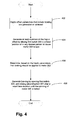
- Fig. 4 is a flow diagram of the functionality of system 10 when providing haptic effects with braking in accordance with one embodiment of the present invention.
- the functionality of the flow diagram of Fig. 4 is implemented by software (e.g., haptic effects module 22) stored in memory or other computer readable or tangible medium, and executed by a processor.
- the functionality may be performed by hardware (e.g., through the use of an application specific integrated circuit ("ASIC"), a programmable gate array (“PGA”), a field programmable gate array (“FPGA”), etc.), or any combination of hardware and software.
- ASIC application specific integrated circuit
- PGA programmable gate array
- FPGA field programmable gate array
- haptic effect parameters that include braking are generated or retrieved from memory or another source.
- the parameters may include high level parameters that define a particular haptic effect, such as magnitude, frequency and duration, or may be formed of low level parameters such as motor voltages.
- the braking typically provides a crisp feeling and can be used, for example, to simulate a mechanical key when a user touches a touchscreen implemented key.
- first switch 304 is opened, and second switch 301 is closed after a small time duration until the spinning of motor 303 is halted.
- the closing of switch 301 adds a "shorting load" across motor 303.
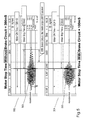
- Fig. 5 illustrates two graphs 502 and 504 of acceleration vs. time for a haptic effect.
- Graph 502 is a prior art graph of a haptically-enabled system without circuit 16 of Fig. 3 .
- Graph 504 is a graph of a haptically-enabled system with circuit 16 (i.e., the "brake circuit") in accordance with embodiments of the present invention.
- an acceleration curve 503 of graph 502 without the braking circuit, after spinning for 300ms, the motor takes 300ms to stop.
Landscapes
- Engineering & Computer Science (AREA)
- General Engineering & Computer Science (AREA)
- Theoretical Computer Science (AREA)
- Human Computer Interaction (AREA)
- Physics & Mathematics (AREA)
- General Physics & Mathematics (AREA)
- Power Engineering (AREA)
- User Interface Of Digital Computer (AREA)
- Apparatuses For Generation Of Mechanical Vibrations (AREA)
- Position Input By Displaying (AREA)
- Stopping Of Electric Motors (AREA)
- Control Of Direct Current Motors (AREA)
Abstract
Description
- This application claims priority of
U.S. Provisional Patent Application Serial No. 61/721,231, filed on November 1, 2012 - One embodiment of the present invention is directed to an actuator. More particularly, one embodiment of the present invention is directed to a drive circuit for an actuator used to create vibrations on a haptically-enabled device.
- Electronic device manufacturers strive to produce a rich interface for users. Conventional devices use visual and auditory cues to provide feedback to a user. In some interface devices, kinesthetic feedback (such as active and resistive force feedback) and/or tactile feedback (such as vibration, texture, and heat) is also provided to the user, more generally known collectively as "haptic feedback" or "haptic effects." Haptic feedback can provide cues that enhance and simplify the user interface. Specifically, vibration effects, or vibrotactile haptic effects, may be useful in providing cues to users of electronic devices to alert the user to specific events, or provide realistic feedback to create greater sensory immersion within a simulated or virtual environment.
- Haptic feedback has also been increasingly incorporated in portable electronic devices, such as cellular telephones, smartphones, portable gaming devices, and a variety of other portable electronic devices. For example, some portable gaming applications are capable of vibrating in a manner similar to control devices (e.g., joysticks, etc.) used with larger-scale gaming systems that are configured to provide haptic feedback. Further, devices such as smartphones use haptic effects to cause "buttons" on a touchscreen to feel like their mechanical counterparts when selected by a user.
- In order to generate vibration effects, many devices utilize some type of actuator or haptic output device. Known actuators used for this purpose include an electromagnetic actuator such as an Eccentric Rotating Mass ("ERM") actuator in which an eccentric mass is moved by a motor. Typically, an ERM requires a bidirectional signal (i.e., an alternating positive voltage and negative voltage signal) in order to create a braking effect, which provides for a crisper dynamic signal. However, most portable electronic devices generate direct current only, so a special drive circuit is required to generate the bidirectional signal. The typical circuit includes an H-bridge, which is a circuit that includes four transistors/switches. However, for portable devices, cost is an important driving factor, and the cost of four switches may be disproportionally high relative to the total cost of the device.
- One embodiment is a haptically-enabled system that includes an actuator that has a first terminal and a second terminal. The second terminal is coupled to a voltage source, and a first switch is coupled to the first terminal and to ground. A second switch is coupled to the actuator. The second switch is parallel to the actuator.
-
-
Fig. 1 is a block diagram of a haptically-enabled system in accordance with one embodiment of the present invention. -
Fig. 2 is a partial perspective view of an ERM embodiment of the actuator ofFig. 1 in accordance with one embodiment of the present invention. -
Fig. 3 is a circuit diagram of an actuator drive circuit in combination with the actuator ofFig. 1 in accordance with an embodiment of the present invention. -
Fig. 4 is a flow diagram of the functionality of the system when providing haptic effects with braking in accordance with one embodiment of the present invention. -
Fig. 5 illustrates two graphs of acceleration vs. time for a haptic effect. - One embodiment is a drive circuit that provides a programmable shorting load across an actuator/motor. The activation of the shorting load when the actuator is spinning brakes the actuator by stopping the spinning after a relatively short time duration without the need to apply a reverse polarity voltage.
-
Fig. 1 is a block diagram of a haptically-enabledsystem 10 in accordance with one embodiment of the present invention.System 10 includes a touchsensitive surface 11 or other type of user interface mounted within ahousing 15, and may include mechanical keys/buttons 13. internal tosystem 10 is a haptic feedback system that generates vibrations onsystem 10. In one embodiment, the vibrations are generated ontouch surface 11. - The haptic feedback system includes a processor or
controller 12. Coupled toprocessor 12 is amemory 20 and anactuator drive circuit 16, which is coupled to anactuator 18.Actuator 18 can be any type of Direct Current ("DC") motor, and in one embodiment is an Eccentric Rotating Mass ("ERM") actuator.Processor 12 may be any type of general purpose processor, or could be a processor specifically designed to provide haptic effects, such as an application-specific integrated circuit ("ASIC").Processor 12 may be the same processor that operates theentire system 10, or may be a separate processor.Processor 12 can decide what haptic effects are to be played and the order in which the effects are played based on high level parameters. In general, the high level parameters that define a particular haptic effect include magnitude, frequency and duration. Low level parameters such as streaming motor commands could also be used to determine a particular haptic effect. A haptic effect may be considered "dynamic" if it includes some variation of these parameters when the haptic effect is generated or a variation of these parameters based on a user's interaction. -
Processor 12 outputs the control signals toactuator drive circuit 16, which includes electronic components and circuitry used to supplyactuator 18 with the required electrical current and voltage (i.e., "motor signals") to cause the desired haptic effects.System 10 may include more than oneactuator 18, and each actuator may include aseparate drive circuit 16, all coupled to acommon processor 12.Memory device 20 can be any type of storage device or computer-readable medium, such as random access memory ("RAM") or read-only memory ("ROM").Memory 20 stores instructions executed byprocessor 12. Among the instructions,memory 20 includes ahaptic effects module 22 which are instructions that, when executed byprocessor 12, generate drive signals foractuator 18 that provide haptic effects with braking, as disclosed in more detail below.Memory 20 may also be located internal toprocessor 12, or any combination of internal and external memory. -
Touch surface 11 recognizes touches, and may also recognize the position and magnitude of touches on the surface. The data corresponding to the touches is sent toprocessor 12, or another processor withinsystem 10, andprocessor 12 interprets the touches and in response generates haptic effect signals.Touch surface 11 may sense touches using any sensing technology, including capacitive sensing, resistive sensing, surface acoustic wave sensing, pressure sensing, optical sensing, etc.Touch surface 11 may sense multi-touch contacts and may be capable of distinguishing multiple touches that occur at the same time.Touch surface 11 may be a touchscreen that generates and displays images for the user to interact with, such as keys, dials, etc., or may be a touchpad with minimal or no images. -
System 10 may be a handheld device, such a cellular telephone, personal digital assistant ("PDA"), smartphone, computer tablet, gaming console, etc., or may be any other type of device that includes a haptic effect system that includes one or more actuators. The user interface may be a touch sensitive surface, or can be any other type of user interface such as a mouse, touchpad, mini-joystick, scroll wheel, trackball, game pads or game controllers, etc. In embodiments with more than one actuator, each actuator may have a different rotational capability in order to create a wide range of haptic effects on the device. -
Fig. 2 is a partial perspective view of an ERM embodiment ofactuator 18 ofFig. 1 in accordance with one embodiment of the present invention.ERM 200 includes a rotatingmass 201 having an off-center weight 203 that rotates about an axis ofrotation 205. In operation, any type of motor may be coupled toERM 200 to cause rotation in one or both directions around axis ofrotation 205 in response to the amount and polarity of voltage applied to the motor across two leads of the motor (not shown inFig. 2 ). An application of voltage at one polarity will have an acceleration effect and cause theERM 200 to increase its rotational speed in one direction, and an application of voltage in the opposite polarity will have a braking effect and cause theERM 200 to decrease or even reverse its rotational speed in the opposite direction. However, as discussed above, the drive circuit required to apply a bi-directional signal/voltage to achieve haptic effect braking typically includes a relatively expensive H-bridge. -
Fig. 3 is a circuit diagram ofactuator drive circuit 16 in combination withactuator 18 ofFig. 1 in accordance with an embodiment of the present invention. Incircuit 16, aDC motor 303 is coupled on one terminal to ground through afirst switch 304 and coupled on the other terminal to the voltage of the circuit (i.e., "Vcc").Motor 303 can be actuator 18, and in one embodiment is an ERM actuator. In parallel tomotor 303 is asecond switch 301 and aresistor 302.Resistor 302 is optional and provides a safety function of protectingswitches switches resistor 302 can also be incorporated intoswitch 301 so it is not a separate component. In one embodiment, bothswitches -
Circuit 16 further includes adiode 305 and acapacitor 306 in parallel tomotor 303.Diode 305 andcapacitor 306 suppress spikes onmotor 303 and are also optional components. - The value of
resistor 302 is a tradeoff between motor braking current and switch safety precautions. The reverse voltage ofdiode 305 and the rated voltage ofcapacitor 306 in one embodiment are greater than the operational voltage ofmotor 303 plus the amplitude of any back electromotive force ("EMF") spikes created. The forward voltage ofdiode 305 can be a wide range (e.g., 0.2V or 0.7V), andcapacitor 306 is non-polarized in one embodiment. - In operation,
first switch 304 andsecond switch 301 are normally open and in thiscondition motor 303 does not spin.Motor 303 is turned on and begins spinning whenswitch 304 is closed. By keepingswitch 304 continuously closed,motor 303 will eventually reach a peak speed to create one type of haptic effect. Switch 304 can be opened and closed and repeated to achieve a duty cycle ofmotor 303 to create other types of haptic effects. - When
motor 303 is to be braked,first switch 304 is opened, and after a short pause to prevent both switches from being closed at the same time (e.g., one or two microseconds),second switch 301 is closed. This causesmotor 303 to brake, and whenmotor 303 stops moving,switch 304 is opened, and then switches 304 and 301 can remain open. - In another embodiment, instead of a first motor terminal coupled to a voltage source and the second motor terminal coupled through a switch to ground, as shown in
Fig. 3 , an inverse configuration can be implemented. Specifically, in this embodiment, a first motor terminal is coupled to ground and a second motor terminal is coupled through a switch to the voltage source. -
Fig. 4 is a flow diagram of the functionality ofsystem 10 when providing haptic effects with braking in accordance with one embodiment of the present invention. In one embodiment, the functionality of the flow diagram ofFig. 4 is implemented by software (e.g., haptic effects module 22) stored in memory or other computer readable or tangible medium, and executed by a processor. In other embodiments, the functionality may be performed by hardware (e.g., through the use of an application specific integrated circuit ("ASIC"), a programmable gate array ("PGA"), a field programmable gate array ("FPGA"), etc.), or any combination of hardware and software. - At 402, haptic effect parameters that include braking are generated or retrieved from memory or another source. The parameters may include high level parameters that define a particular haptic effect, such as magnitude, frequency and duration, or may be formed of low level parameters such as motor voltages. The braking typically provides a crisp feeling and can be used, for example, to simulate a mechanical key when a user touches a touchscreen implemented key.
- At 404, at least a portion of the haptic effect is generated by closing
first switch 304 in a fixed position or in any desired pattern to causemotor 303 to spin. - At 406, it is determined, based on the haptic parameters, that braking should be applied to
motor 303. - At 408, to generate the braking,
first switch 304 is opened, andsecond switch 301 is closed after a small time duration until the spinning ofmotor 303 is halted. The closing ofswitch 301 adds a "shorting load" acrossmotor 303. - As discussed, embodiments provide braking on an actuator without the need for bi-directional signals or an H-bridge circuit.
Fig. 5 illustrates twographs Graph 502 is a prior art graph of a haptically-enabled system withoutcircuit 16 ofFig. 3 .Graph 504 is a graph of a haptically-enabled system with circuit 16 (i.e., the "brake circuit") in accordance with embodiments of the present invention. As shown by anacceleration curve 503 ofgraph 502, without the braking circuit, after spinning for 300ms, the motor takes 300ms to stop. In comparison, as shown by anacceleration curve 505 ofgraph 504, with the braking circuit (i.e., circuit 16) in accordance with embodiments of the present invention, after spinning for 300ms, the motor only takes 100ms to stop. As disclosed, embodiments cause a DC motor to brake by applying a shorting load across the motor, which stops the spinning of the motor after a relatively short time duration. Therefore, haptic effects with braking can be effectively generated without the need for bi-directional voltages. - Several embodiments are specifically illustrated and/or described herein. However, it will be appreciated that modifications and variations of the disclosed embodiments are covered by the above teachings and within the purview of the appended claims without departing from the spirit and intended scope of the invention.
Claims (15)
- A haptically-enabled system comprising:an actuator comprising a first terminal and a second terminal, wherein the second terminal is coupled to a voltage source;a first switch coupled to the first terminal and to ground; anda second switch coupled to the actuator, wherein the second switch is parallel to the actuator.
- A haptically-enabled system comprising:an actuator comprising a first terminal and a second terminal, wherein the second terminal is coupled to ground;a first switch coupled to the first terminal and to a voltage source; anda second switch coupled to the actuator, wherein the second switch is parallel to the actuator.
- The system of claim 1 or 2, further comprising a capacitor and a diode coupled to the actuator, wherein the capacitor is parallel to the diode and the actuator.
- The system of claim 1 or 2, further comprising a resistor coupled to and in series with the second switch.
- The system of claim 1 or 2, further comprising a processor coupled to the actuator and adapted to generate a haptic effect with braking, the generating comprising:closing the first switch while opening the second switch to cause the actuator to rotate to generate a first portion of a haptic effect; andopening the first switch and closing the second switch to cause the actuator to stop rotating.
- The system of claim 1 or 2, wherein the actuator comprises an Eccentric Rotating Mass coupled to a motor.
- The system of claim 5, wherein the haptic effect is generated from haptic effect parameters received or generated by the processor.
- The system of claim 7, wherein the haptic effect parameters comprise at least one of magnitude, frequency or duration.
- The system of claim 5, further comprising a touchscreen with keys coupled to the processor, wherein the generated haptic effect simulates a mechanical key when an object contacts one or more of the touchscreen keys.
- A drive circuit for an Eccentric Rotating Mass actuator having a first terminal and a second terminal, the drive circuit comprising:a voltage node that couples the second terminal to a voltage source;a first switch coupled to the first terminal and to ground; anda second switch coupled to the voltage node and to the first terminal.
- The drive circuit of claim 10, further comprising a capacitor and a diode coupled to ground and the first terminal, wherein the capacitor is parallel to the diode and the actuator.
- The drive circuit of claim 10, further comprising a resistor coupled between the second switch and the first terminal and in series with the second switch.
- The drive circuit of claim 10, further comprising:a controller coupled to the first switch and the second switch and adapted to generate a haptic effect with braking, the generating comprising:closing the first switch while opening the second switch to cause the actuator to rotate to generate a first portion of the haptic effect; andopening the first switch and closing the second switch to cause the actuator to stop rotating.
- A method of generating a haptic effect with braking, the method comprising:closing a first switch while opening a second switch to cause an actuator to rotate to generate a first portion of a haptic effect; andopening the first switch and closing the second switch to cause the actuator to stop rotating, wherein the second switch provides a short across the actuator.
- The method of claim 14, wherein the method using a drive circuit according to any of claims 10 to 13.
Applications Claiming Priority (2)
| Application Number | Priority Date | Filing Date | Title |
|---|---|---|---|
| US201261721231P | 2012-11-01 | 2012-11-01 | |
| US13/785,699 US9218075B2 (en) | 2012-11-01 | 2013-03-05 | Haptically-enabled system with braking |
Publications (2)
| Publication Number | Publication Date |
|---|---|
| EP2752731A1 true EP2752731A1 (en) | 2014-07-09 |
| EP2752731B1 EP2752731B1 (en) | 2015-07-29 |
Family
ID=50546425
Family Applications (1)
| Application Number | Title | Priority Date | Filing Date |
|---|---|---|---|
| EP13190903.8A Not-in-force EP2752731B1 (en) | 2012-11-01 | 2013-10-30 | Haptically-enabled system with braking |
Country Status (5)
| Country | Link |
|---|---|
| US (2) | US9218075B2 (en) |
| EP (1) | EP2752731B1 (en) |
| JP (2) | JP6404559B2 (en) |
| KR (1) | KR20140056076A (en) |
| CN (2) | CN108628456A (en) |
Families Citing this family (8)
| Publication number | Priority date | Publication date | Assignee | Title |
|---|---|---|---|---|
| KR102019505B1 (en) * | 2014-09-02 | 2019-09-06 | 애플 인크. | Haptic notifications |
| US9846484B2 (en) * | 2014-12-04 | 2017-12-19 | Immersion Corporation | Systems and methods for controlling haptic signals |
| US10317999B2 (en) * | 2017-10-13 | 2019-06-11 | Facebook Technologies, Llc | Vibrotactile driver circuit for haptic devices |
| CN110162171B (en) * | 2019-04-18 | 2021-02-09 | 瑞声科技(新加坡)有限公司 | Motor driving signal setting method, electronic device and storage medium |
| US11662821B2 (en) * | 2020-04-16 | 2023-05-30 | Cirrus Logic, Inc. | In-situ monitoring, calibration, and testing of a haptic actuator |
| US12242671B2 (en) * | 2020-08-27 | 2025-03-04 | Qualcomm Incorporated | Braking control of haptic feedback device |
| US12176057B2 (en) * | 2021-11-08 | 2024-12-24 | Cirrus Logic Inc. | Systems and methods for minimizing idle channel noise in a single-ended amplifier |
| CN115032922B (en) * | 2022-05-25 | 2025-12-30 | 之江实验室 | A Scalable Bidirectional Current Control Integrated Circuit for Dense Dot Matrix Vision and Touch Sensing |
Citations (3)
| Publication number | Priority date | Publication date | Assignee | Title |
|---|---|---|---|---|
| US20060119573A1 (en) * | 2004-11-30 | 2006-06-08 | Grant Danny A | Systems and methods for controlling a resonant device for generating vibrotactile haptic effects |
| US20120232780A1 (en) * | 2005-06-27 | 2012-09-13 | Coactive Drive Corporation | Asymmetric and general vibration waveforms from multiple synchronized vibration actuators |
| US20120229264A1 (en) * | 2011-03-09 | 2012-09-13 | Analog Devices, Inc. | Smart linear resonant actuator control |
Family Cites Families (31)
| Publication number | Priority date | Publication date | Assignee | Title |
|---|---|---|---|---|
| GB2113028B (en) * | 1981-12-31 | 1986-09-03 | Burroughs Corp | Data disc rotating systems |
| JPH04271050A (en) * | 1991-01-21 | 1992-09-28 | Alps Electric Co Ltd | Motor control circuit in rotary head type tape player |
| JPH0583986A (en) * | 1991-09-20 | 1993-04-02 | Matsushita Electric Works Ltd | Motor control circuit |
| JPH07147767A (en) * | 1993-11-22 | 1995-06-06 | Sanden Corp | Power controller motor driver |
| JPH0833389A (en) * | 1994-07-14 | 1996-02-02 | Jeco Co Ltd | Actuator |
| JPH0974740A (en) * | 1995-09-01 | 1997-03-18 | Canon Inc | DC power controller |
| JPH1169873A (en) * | 1997-08-21 | 1999-03-09 | Otax Kk | Motor control device for electric tool |
| WO1999063643A1 (en) * | 1998-06-05 | 1999-12-09 | Milwaukee Electric Tool Corporation | Braking and control circuit for electric power tools |
| US6371587B1 (en) * | 1999-05-31 | 2002-04-16 | Seiko Epson Corporation | Ink jet recording apparatus |
| US8169402B2 (en) * | 1999-07-01 | 2012-05-01 | Immersion Corporation | Vibrotactile haptic feedback devices |
| DE19931972A1 (en) * | 1999-07-09 | 2001-01-11 | Wabco Gmbh & Co Ohg | Circuit arrangement for operating an electromagnetic actuator |
| DE20080209U1 (en) * | 1999-09-28 | 2001-08-09 | Immersion Corp | Control of haptic sensations for interface devices with vibrotactile feedback |
| FI20020582A7 (en) * | 2002-03-26 | 2003-09-27 | Nokia Oyj | User interface for a portable communications device |
| US7742036B2 (en) * | 2003-12-22 | 2010-06-22 | Immersion Corporation | System and method for controlling haptic devices having multiple operational modes |
| JP2006042477A (en) * | 2004-07-26 | 2006-02-09 | Smk Corp | Wave shaping circuit |
| JP2006222826A (en) * | 2005-02-14 | 2006-08-24 | Fujitsu Ltd | Mobile information terminal with call function |
| US7920694B2 (en) * | 2006-02-03 | 2011-04-05 | Immersion Corporation | Generation of consistent haptic effects |
| US7890863B2 (en) * | 2006-10-04 | 2011-02-15 | Immersion Corporation | Haptic effects with proximity sensing |
| US8378965B2 (en) * | 2007-04-10 | 2013-02-19 | Immersion Corporation | Vibration actuator with a unidirectional drive |
| GB2467551B (en) * | 2009-02-05 | 2011-05-18 | Restech Ltd | Electromagnetic field energy recycling |
| EP2329636A1 (en) * | 2008-07-15 | 2011-06-08 | Immersion Corporation | Systems and methods for haptic message transmission |
| JP5253950B2 (en) * | 2008-09-29 | 2013-07-31 | 日本電産コパル株式会社 | Engine mount actuator |
| US7843277B2 (en) * | 2008-12-16 | 2010-11-30 | Immersion Corporation | Haptic feedback generation based on resonant frequency |
| US8378979B2 (en) * | 2009-01-27 | 2013-02-19 | Amazon Technologies, Inc. | Electronic device with haptic feedback |
| JP5553296B2 (en) * | 2009-03-09 | 2014-07-16 | Icファン V−Tech株式会社 | Electronics |
| US9891708B2 (en) * | 2009-06-09 | 2018-02-13 | Immersion Corporation | Method and apparatus for generating haptic effects using actuators |
| JP5141641B2 (en) * | 2009-06-15 | 2013-02-13 | コニカミノルタビジネステクノロジーズ株式会社 | Power supply control apparatus, image forming apparatus, and power supply apparatus control method |
| JP5645967B2 (en) * | 2009-12-23 | 2014-12-24 | ローベルト ボツシユ ゲゼルシヤフト ミツト ベシユレンクテル ハフツングRobert Bosch Gmbh | Braking device for universal motor |
| US8797152B2 (en) * | 2011-06-28 | 2014-08-05 | New Scale Technologies, Inc. | Haptic actuator apparatuses and methods thereof |
| US20130033366A1 (en) * | 2011-08-01 | 2013-02-07 | Mcdonough Colin Albright | Method and system for providing haptic feedback of variable intensity |
| JP5879887B2 (en) * | 2011-10-03 | 2016-03-08 | セイコーエプソン株式会社 | Power generator |
-
2013
- 2013-03-05 US US13/785,699 patent/US9218075B2/en not_active Expired - Fee Related
- 2013-10-22 JP JP2013219512A patent/JP6404559B2/en not_active Expired - Fee Related
- 2013-10-30 KR KR1020130129888A patent/KR20140056076A/en not_active Ceased
- 2013-10-30 EP EP13190903.8A patent/EP2752731B1/en not_active Not-in-force
- 2013-11-01 CN CN201810470509.0A patent/CN108628456A/en active Pending
- 2013-11-01 CN CN201310534636.XA patent/CN103809745B/en not_active Expired - Fee Related
-
2015
- 2015-12-21 US US14/976,251 patent/US10209774B2/en not_active Expired - Fee Related
-
2018
- 2018-09-12 JP JP2018170331A patent/JP2019008823A/en active Pending
Patent Citations (3)
| Publication number | Priority date | Publication date | Assignee | Title |
|---|---|---|---|---|
| US20060119573A1 (en) * | 2004-11-30 | 2006-06-08 | Grant Danny A | Systems and methods for controlling a resonant device for generating vibrotactile haptic effects |
| US20120232780A1 (en) * | 2005-06-27 | 2012-09-13 | Coactive Drive Corporation | Asymmetric and general vibration waveforms from multiple synchronized vibration actuators |
| US20120229264A1 (en) * | 2011-03-09 | 2012-09-13 | Analog Devices, Inc. | Smart linear resonant actuator control |
Also Published As
| Publication number | Publication date |
|---|---|
| US20160103492A1 (en) | 2016-04-14 |
| US10209774B2 (en) | 2019-02-19 |
| US20140117887A1 (en) | 2014-05-01 |
| US9218075B2 (en) | 2015-12-22 |
| KR20140056076A (en) | 2014-05-09 |
| JP2019008823A (en) | 2019-01-17 |
| JP6404559B2 (en) | 2018-10-10 |
| CN108628456A (en) | 2018-10-09 |
| CN103809745A (en) | 2014-05-21 |
| EP2752731B1 (en) | 2015-07-29 |
| JP2014093086A (en) | 2014-05-19 |
| CN103809745B (en) | 2018-06-01 |
Similar Documents
| Publication | Publication Date | Title |
|---|---|---|
| US10209774B2 (en) | Haptically-enabled system with braking | |
| US10101815B2 (en) | Eccentric rotating mass actuator optimization for haptic effects | |
| EP2762999B1 (en) | Overdrive voltage for an actuator to generate haptic effects | |
| US9196135B2 (en) | Uniform haptic actuator response with a variable supply voltage | |
| US8994518B2 (en) | Haptic feedback generation based on resonant frequency | |
| US9733704B2 (en) | User interface impact actuator | |
| US8378965B2 (en) | Vibration actuator with a unidirectional drive | |
| KR20150041743A (en) | Generating haptic effects while minimizing cascading |
Legal Events
| Date | Code | Title | Description |
|---|---|---|---|
| 17P | Request for examination filed |
Effective date: 20131030 |
|
| AK | Designated contracting states |
Kind code of ref document: A1 Designated state(s): AL AT BE BG CH CY CZ DE DK EE ES FI FR GB GR HR HU IE IS IT LI LT LU LV MC MK MT NL NO PL PT RO RS SE SI SK SM TR |
|
| AX | Request for extension of the european patent |
Extension state: BA ME |
|
| PUAI | Public reference made under article 153(3) epc to a published international application that has entered the european phase |
Free format text: ORIGINAL CODE: 0009012 |
|
| R17P | Request for examination filed (corrected) |
Effective date: 20141216 |
|
| RBV | Designated contracting states (corrected) |
Designated state(s): AL AT BE BG CH CY CZ DE DK EE ES FI FR GB GR HR HU IE IS IT LI LT LU LV MC MK MT NL NO PL PT RO RS SE SI SK SM TR |
|
| GRAP | Despatch of communication of intention to grant a patent |
Free format text: ORIGINAL CODE: EPIDOSNIGR1 |
|
| RIC1 | Information provided on ipc code assigned before grant |
Ipc: H02N 2/10 20060101ALI20150128BHEP Ipc: H01H 1/00 20060101ALN20150128BHEP Ipc: G06F 3/01 20060101AFI20150128BHEP Ipc: H02P 3/12 20060101ALI20150128BHEP Ipc: G06F 3/041 20060101ALI20150128BHEP |
|
| RIC1 | Information provided on ipc code assigned before grant |
Ipc: H01H 1/00 20060101ALN20150218BHEP Ipc: G06F 3/041 20060101ALI20150218BHEP Ipc: G06F 3/01 20060101AFI20150218BHEP Ipc: H02P 3/12 20060101ALI20150218BHEP Ipc: H02N 2/10 20060101ALI20150218BHEP |
|
| INTG | Intention to grant announced |
Effective date: 20150303 |
|
| GRAS | Grant fee paid |
Free format text: ORIGINAL CODE: EPIDOSNIGR3 |
|
| GRAA | (expected) grant |
Free format text: ORIGINAL CODE: 0009210 |
|
| AK | Designated contracting states |
Kind code of ref document: B1 Designated state(s): AL AT BE BG CH CY CZ DE DK EE ES FI FR GB GR HR HU IE IS IT LI LT LU LV MC MK MT NL NO PL PT RO RS SE SI SK SM TR |
|
| REG | Reference to a national code |
Ref country code: GB Ref legal event code: FG4D |
|
| REG | Reference to a national code |
Ref country code: CH Ref legal event code: EP |
|
| REG | Reference to a national code |
Ref country code: AT Ref legal event code: REF Ref document number: 739780 Country of ref document: AT Kind code of ref document: T Effective date: 20150815 |
|
| REG | Reference to a national code |
Ref country code: IE Ref legal event code: FG4D |
|
| RAP2 | Party data changed (patent owner data changed or rights of a patent transferred) |
Owner name: IMMERSION CORPORATION |
|
| REG | Reference to a national code |
Ref country code: DE Ref legal event code: R096 Ref document number: 602013002440 Country of ref document: DE |
|
| REG | Reference to a national code |
Ref country code: AT Ref legal event code: MK05 Ref document number: 739780 Country of ref document: AT Kind code of ref document: T Effective date: 20150729 |
|
| REG | Reference to a national code |
Ref country code: LT Ref legal event code: MG4D |
|
| REG | Reference to a national code |
Ref country code: NL Ref legal event code: MP Effective date: 20150729 |
|
| PG25 | Lapsed in a contracting state [announced via postgrant information from national office to epo] |
Ref country code: NO Free format text: LAPSE BECAUSE OF FAILURE TO SUBMIT A TRANSLATION OF THE DESCRIPTION OR TO PAY THE FEE WITHIN THE PRESCRIBED TIME-LIMIT Effective date: 20151029 Ref country code: GR Free format text: LAPSE BECAUSE OF FAILURE TO SUBMIT A TRANSLATION OF THE DESCRIPTION OR TO PAY THE FEE WITHIN THE PRESCRIBED TIME-LIMIT Effective date: 20151030 Ref country code: LT Free format text: LAPSE BECAUSE OF FAILURE TO SUBMIT A TRANSLATION OF THE DESCRIPTION OR TO PAY THE FEE WITHIN THE PRESCRIBED TIME-LIMIT Effective date: 20150729 Ref country code: LV Free format text: LAPSE BECAUSE OF FAILURE TO SUBMIT A TRANSLATION OF THE DESCRIPTION OR TO PAY THE FEE WITHIN THE PRESCRIBED TIME-LIMIT Effective date: 20150729 Ref country code: FI Free format text: LAPSE BECAUSE OF FAILURE TO SUBMIT A TRANSLATION OF THE DESCRIPTION OR TO PAY THE FEE WITHIN THE PRESCRIBED TIME-LIMIT Effective date: 20150729 |
|
| PG25 | Lapsed in a contracting state [announced via postgrant information from national office to epo] |
Ref country code: PT Free format text: LAPSE BECAUSE OF FAILURE TO SUBMIT A TRANSLATION OF THE DESCRIPTION OR TO PAY THE FEE WITHIN THE PRESCRIBED TIME-LIMIT Effective date: 20151130 Ref country code: IS Free format text: LAPSE BECAUSE OF FAILURE TO SUBMIT A TRANSLATION OF THE DESCRIPTION OR TO PAY THE FEE WITHIN THE PRESCRIBED TIME-LIMIT Effective date: 20151129 Ref country code: PL Free format text: LAPSE BECAUSE OF FAILURE TO SUBMIT A TRANSLATION OF THE DESCRIPTION OR TO PAY THE FEE WITHIN THE PRESCRIBED TIME-LIMIT Effective date: 20150729 Ref country code: AT Free format text: LAPSE BECAUSE OF FAILURE TO SUBMIT A TRANSLATION OF THE DESCRIPTION OR TO PAY THE FEE WITHIN THE PRESCRIBED TIME-LIMIT Effective date: 20150729 Ref country code: RS Free format text: LAPSE BECAUSE OF FAILURE TO SUBMIT A TRANSLATION OF THE DESCRIPTION OR TO PAY THE FEE WITHIN THE PRESCRIBED TIME-LIMIT Effective date: 20150729 Ref country code: ES Free format text: LAPSE BECAUSE OF FAILURE TO SUBMIT A TRANSLATION OF THE DESCRIPTION OR TO PAY THE FEE WITHIN THE PRESCRIBED TIME-LIMIT Effective date: 20150729 Ref country code: SE Free format text: LAPSE BECAUSE OF FAILURE TO SUBMIT A TRANSLATION OF THE DESCRIPTION OR TO PAY THE FEE WITHIN THE PRESCRIBED TIME-LIMIT Effective date: 20150729 Ref country code: HR Free format text: LAPSE BECAUSE OF FAILURE TO SUBMIT A TRANSLATION OF THE DESCRIPTION OR TO PAY THE FEE WITHIN THE PRESCRIBED TIME-LIMIT Effective date: 20150729 |
|
| REG | Reference to a national code |
Ref country code: FR Ref legal event code: PLFP Year of fee payment: 3 |
|
| PG25 | Lapsed in a contracting state [announced via postgrant information from national office to epo] |
Ref country code: NL Free format text: LAPSE BECAUSE OF FAILURE TO SUBMIT A TRANSLATION OF THE DESCRIPTION OR TO PAY THE FEE WITHIN THE PRESCRIBED TIME-LIMIT Effective date: 20150729 |
|
| PG25 | Lapsed in a contracting state [announced via postgrant information from national office to epo] |
Ref country code: EE Free format text: LAPSE BECAUSE OF FAILURE TO SUBMIT A TRANSLATION OF THE DESCRIPTION OR TO PAY THE FEE WITHIN THE PRESCRIBED TIME-LIMIT Effective date: 20150729 Ref country code: DK Free format text: LAPSE BECAUSE OF FAILURE TO SUBMIT A TRANSLATION OF THE DESCRIPTION OR TO PAY THE FEE WITHIN THE PRESCRIBED TIME-LIMIT Effective date: 20150729 Ref country code: SK Free format text: LAPSE BECAUSE OF FAILURE TO SUBMIT A TRANSLATION OF THE DESCRIPTION OR TO PAY THE FEE WITHIN THE PRESCRIBED TIME-LIMIT Effective date: 20150729 Ref country code: CZ Free format text: LAPSE BECAUSE OF FAILURE TO SUBMIT A TRANSLATION OF THE DESCRIPTION OR TO PAY THE FEE WITHIN THE PRESCRIBED TIME-LIMIT Effective date: 20150729 Ref country code: IT Free format text: LAPSE BECAUSE OF FAILURE TO SUBMIT A TRANSLATION OF THE DESCRIPTION OR TO PAY THE FEE WITHIN THE PRESCRIBED TIME-LIMIT Effective date: 20150729 |
|
| REG | Reference to a national code |
Ref country code: DE Ref legal event code: R097 Ref document number: 602013002440 Country of ref document: DE |
|
| PG25 | Lapsed in a contracting state [announced via postgrant information from national office to epo] |
Ref country code: RO Free format text: LAPSE BECAUSE OF FAILURE TO SUBMIT A TRANSLATION OF THE DESCRIPTION OR TO PAY THE FEE WITHIN THE PRESCRIBED TIME-LIMIT Effective date: 20150729 Ref country code: LU Free format text: LAPSE BECAUSE OF FAILURE TO SUBMIT A TRANSLATION OF THE DESCRIPTION OR TO PAY THE FEE WITHIN THE PRESCRIBED TIME-LIMIT Effective date: 20151030 |
|
| PLBE | No opposition filed within time limit |
Free format text: ORIGINAL CODE: 0009261 |
|
| STAA | Information on the status of an ep patent application or granted ep patent |
Free format text: STATUS: NO OPPOSITION FILED WITHIN TIME LIMIT |
|
| PG25 | Lapsed in a contracting state [announced via postgrant information from national office to epo] |
Ref country code: MC Free format text: LAPSE BECAUSE OF FAILURE TO SUBMIT A TRANSLATION OF THE DESCRIPTION OR TO PAY THE FEE WITHIN THE PRESCRIBED TIME-LIMIT Effective date: 20150729 |
|
| 26N | No opposition filed |
Effective date: 20160502 |
|
| REG | Reference to a national code |
Ref country code: IE Ref legal event code: MM4A |
|
| PG25 | Lapsed in a contracting state [announced via postgrant information from national office to epo] |
Ref country code: SI Free format text: LAPSE BECAUSE OF FAILURE TO SUBMIT A TRANSLATION OF THE DESCRIPTION OR TO PAY THE FEE WITHIN THE PRESCRIBED TIME-LIMIT Effective date: 20150729 |
|
| REG | Reference to a national code |
Ref country code: FR Ref legal event code: PLFP Year of fee payment: 4 |
|
| PG25 | Lapsed in a contracting state [announced via postgrant information from national office to epo] |
Ref country code: IE Free format text: LAPSE BECAUSE OF NON-PAYMENT OF DUE FEES Effective date: 20151030 |
|
| PG25 | Lapsed in a contracting state [announced via postgrant information from national office to epo] |
Ref country code: BE Free format text: LAPSE BECAUSE OF FAILURE TO SUBMIT A TRANSLATION OF THE DESCRIPTION OR TO PAY THE FEE WITHIN THE PRESCRIBED TIME-LIMIT Effective date: 20150729 |
|
| PG25 | Lapsed in a contracting state [announced via postgrant information from national office to epo] |
Ref country code: HU Free format text: LAPSE BECAUSE OF FAILURE TO SUBMIT A TRANSLATION OF THE DESCRIPTION OR TO PAY THE FEE WITHIN THE PRESCRIBED TIME-LIMIT; INVALID AB INITIO Effective date: 20131030 Ref country code: BG Free format text: LAPSE BECAUSE OF FAILURE TO SUBMIT A TRANSLATION OF THE DESCRIPTION OR TO PAY THE FEE WITHIN THE PRESCRIBED TIME-LIMIT Effective date: 20150729 |
|
| REG | Reference to a national code |
Ref country code: CH Ref legal event code: PL |
|
| PG25 | Lapsed in a contracting state [announced via postgrant information from national office to epo] |
Ref country code: CY Free format text: LAPSE BECAUSE OF FAILURE TO SUBMIT A TRANSLATION OF THE DESCRIPTION OR TO PAY THE FEE WITHIN THE PRESCRIBED TIME-LIMIT Effective date: 20150729 |
|
| PG25 | Lapsed in a contracting state [announced via postgrant information from national office to epo] |
Ref country code: LI Free format text: LAPSE BECAUSE OF NON-PAYMENT OF DUE FEES Effective date: 20161031 Ref country code: CH Free format text: LAPSE BECAUSE OF NON-PAYMENT OF DUE FEES Effective date: 20161031 |
|
| PG25 | Lapsed in a contracting state [announced via postgrant information from national office to epo] |
Ref country code: MT Free format text: LAPSE BECAUSE OF FAILURE TO SUBMIT A TRANSLATION OF THE DESCRIPTION OR TO PAY THE FEE WITHIN THE PRESCRIBED TIME-LIMIT Effective date: 20150729 |
|
| REG | Reference to a national code |
Ref country code: FR Ref legal event code: PLFP Year of fee payment: 5 |
|
| PG25 | Lapsed in a contracting state [announced via postgrant information from national office to epo] |
Ref country code: SM Free format text: LAPSE BECAUSE OF FAILURE TO SUBMIT A TRANSLATION OF THE DESCRIPTION OR TO PAY THE FEE WITHIN THE PRESCRIBED TIME-LIMIT Effective date: 20150729 |
|
| PG25 | Lapsed in a contracting state [announced via postgrant information from national office to epo] |
Ref country code: MK Free format text: LAPSE BECAUSE OF FAILURE TO SUBMIT A TRANSLATION OF THE DESCRIPTION OR TO PAY THE FEE WITHIN THE PRESCRIBED TIME-LIMIT Effective date: 20150729 |
|
| REG | Reference to a national code |
Ref country code: FR Ref legal event code: PLFP Year of fee payment: 6 |
|
| PG25 | Lapsed in a contracting state [announced via postgrant information from national office to epo] |
Ref country code: AL Free format text: LAPSE BECAUSE OF FAILURE TO SUBMIT A TRANSLATION OF THE DESCRIPTION OR TO PAY THE FEE WITHIN THE PRESCRIBED TIME-LIMIT Effective date: 20150729 Ref country code: TR Free format text: LAPSE BECAUSE OF FAILURE TO SUBMIT A TRANSLATION OF THE DESCRIPTION OR TO PAY THE FEE WITHIN THE PRESCRIBED TIME-LIMIT Effective date: 20150729 |
|
| PGFP | Annual fee paid to national office [announced via postgrant information from national office to epo] |
Ref country code: DE Payment date: 20181029 Year of fee payment: 6 |
|
| PGFP | Annual fee paid to national office [announced via postgrant information from national office to epo] |
Ref country code: FR Payment date: 20181025 Year of fee payment: 6 Ref country code: GB Payment date: 20181029 Year of fee payment: 6 |
|
| REG | Reference to a national code |
Ref country code: DE Ref legal event code: R119 Ref document number: 602013002440 Country of ref document: DE |
|
| PG25 | Lapsed in a contracting state [announced via postgrant information from national office to epo] |
Ref country code: DE Free format text: LAPSE BECAUSE OF NON-PAYMENT OF DUE FEES Effective date: 20200501 |
|
| GBPC | Gb: european patent ceased through non-payment of renewal fee |
Effective date: 20191030 |
|
| PG25 | Lapsed in a contracting state [announced via postgrant information from national office to epo] |
Ref country code: GB Free format text: LAPSE BECAUSE OF NON-PAYMENT OF DUE FEES Effective date: 20191030 Ref country code: FR Free format text: LAPSE BECAUSE OF NON-PAYMENT OF DUE FEES Effective date: 20191031 |