EP2752359A2 - Base for locking elements - Google Patents
Base for locking elements Download PDFInfo
- Publication number
- EP2752359A2 EP2752359A2 EP12819506.2A EP12819506A EP2752359A2 EP 2752359 A2 EP2752359 A2 EP 2752359A2 EP 12819506 A EP12819506 A EP 12819506A EP 2752359 A2 EP2752359 A2 EP 2752359A2
- Authority
- EP
- European Patent Office
- Prior art keywords
- support
- locking
- locking elements
- vehicle
- members
- Prior art date
- Legal status (The legal status is an assumption and is not a legal conclusion. Google has not performed a legal analysis and makes no representation as to the accuracy of the status listed.)
- Granted
Links
Images



Classifications
-
- B—PERFORMING OPERATIONS; TRANSPORTING
- B62—LAND VEHICLES FOR TRAVELLING OTHERWISE THAN ON RAILS
- B62H—CYCLE STANDS; SUPPORTS OR HOLDERS FOR PARKING OR STORING CYCLES; APPLIANCES PREVENTING OR INDICATING UNAUTHORIZED USE OR THEFT OF CYCLES; LOCKS INTEGRAL WITH CYCLES; DEVICES FOR LEARNING TO RIDE CYCLES
- B62H5/00—Appliances preventing or indicating unauthorised use or theft of cycles; Locks integral with cycles
-
- E—FIXED CONSTRUCTIONS
- E05—LOCKS; KEYS; WINDOW OR DOOR FITTINGS; SAFES
- E05B—LOCKS; ACCESSORIES THEREFOR; HANDCUFFS
- E05B71/00—Locks specially adapted for bicycles, other than padlocks
-
- B—PERFORMING OPERATIONS; TRANSPORTING
- B62—LAND VEHICLES FOR TRAVELLING OTHERWISE THAN ON RAILS
- B62H—CYCLE STANDS; SUPPORTS OR HOLDERS FOR PARKING OR STORING CYCLES; APPLIANCES PREVENTING OR INDICATING UNAUTHORIZED USE OR THEFT OF CYCLES; LOCKS INTEGRAL WITH CYCLES; DEVICES FOR LEARNING TO RIDE CYCLES
- B62H5/00—Appliances preventing or indicating unauthorised use or theft of cycles; Locks integral with cycles
- B62H2005/008—Arrangements or adaptations for supporting U-locks on cycles
Definitions
- the invention relates to a support immobilised by any known means to the structure of a vehicle with two or more wheels, such as a bicycle, motorcycle, quad or the like; the device is intended to prevent the theft of said vehicle or of parts of the same.
- the device is intended to hold one or more locking elements such as a lock or the like, such that when the vehicle is parked, said locking means are applied to the various parts of the vehicle in order to prevent the parts from being removed, while said means remain immobilised on the support when said vehicle is in use and do not interfere with the user.
- the invention also offers an automated embodiment, so that when the "U" members are stored in the device, a support for the lock of the padlock emerges automatically, and when the lock is removed, this support is automatically concealed.
- the invention also introduces means to alert the user that one or both wheels of the vehicle are immobilised by a padlock, avoiding something that happens in other locking devices when the user starts the vehicle without removing the padlock and thus causes damage to the vehicle.
- This support has an irregular perimeter formed by concave and convex elements, or flat concave surfaces, on the lower side of a carrier tray, in front of each other, in such a manner that the "U" members of a conventional padlock can be housed in said concave surfaces, the convex or flat surfaces being used as means for separation, or of separation distance between the concave surfaces of said "U” members, so that they are immobilised when the vehicle is moving, and placed horizontally or vertically in said tray, and, in one of the possible embodiments of the support, with the locking sockets of the "U” members secured to a plate with lugs onto which these sockets lock, when the locking device is not in use.
- the support is formed by two or more bodies with concave-convex surfaces, located on the right and left of the tray, and as an annexe of one of the bodies, the plate which stops the "U” members of the locking device becoming detached from the support and holds the locking sockets when not used for locking.
- the locking device may be a padlock, which has a "U" members the ends of which are immobilised in a locking socket by turning a key.
- the support can incorporate open or closed tubular elements to protect the "U” members from water and the weather in general, these tubular elements having elastic means on one of their ends to avoid longitudinal movement of the "U” members together with a projection from said tubular body, when not in use, and are subject to the vibrations of the vehicle when driving over irregular road surfaces.
- the support is formed by a prismatic body, the smaller side bases of which have grooves for the placement and immobilisation of the corresponding "U" members, and in one of the front bases there are pivots to immobilise the sockets.
- the improved device comprises two separate coplanar tubes joined by one or more plates, with other tubes joined to these tubes that have a groove along which the support of the padlock lock slides.
- the automation of the device is achieved by means of elements which enable when the vehicle is in movement, and the "U" members of the padlock are inserted into the upper tubes, this insertion generates the outward movement of a support for the immobilisation of the lock of the padlock, in the lower tubes joined by any means to the upper tubes.
- the upper tubes are placed longitudinally and are joined with a plate that has the corresponding holes, which have been designed for the attachment of the device to a vehicle with two or more wheels, and inside which there are springs the ends of which are secured to the tubes by means of a plug.
- the lower tubes are fitted in the in lower part of the upper tubes, and their side surface has a non-through elliptical groove, designed to hold the support for the lock of a padlock.
- the support for the padlock has a plate, from the ends of which emerge perpendicularly lugs with grooves to facilitate immobilisation of the lock of the padlock.
- the improved device incorporates a kinematic chain, formed by the union of levers which convert a movement of the of the padlock "U” members from left to right, in a reverse movement of the lock of the padlock.
- the invention is complemented with a contact breaker, contact sensor plate or similar device which combined with the support enables a luminous or acoustic warning to be switched on or off, warning the user if the padlock is locked, or there can be a electrical cut-off connection to stop the engine of the vehicle from starting.
- the support described in the improvements is formed by a body or perforated iron plate to reduce its weight, in one of the faces of which there have been welded some tubular elements on the right and left of the body of the support, the first two holding some rods one of the ends of which are finished with lugs, and the second with cavities for inserting the "U" members of the padlock when not in use.
- the rods-lugs are in turn joined by a brace perpendicular to them, which may be pushed forwards and backward thanks to a bent plate which the user presses to make the lugs come out of the tubular element and so immobilise their end to the box lock of the padlock.
- these rods can incorporate extensions by which, due to their annular configuration, allows the passage of the "U" members of a conventional padlock, to lock the vehicle user's helmet.
- a totally conventional carrier tray (10) comprising generally some crossbeam rods (11), reinforced with crossmember rods (12) also parallel to each other, which is attached (10) to a two-wheeled vehicle, for instance a bicycle, by means of rods (16), which, in one of the embodiments, comprise a horizontal part (16 b), and a vertical part (16a), with a flattened area (14) having (14) an orifice (15), which by means of the corresponding nuts and bolts (not shown in the figures) the carrier tray (10) is secured to the bicycle (or similar vehicle) frame.
- rods (16) which, in one of the embodiments, comprise a horizontal part (16 b), and a vertical part (16a), with a flattened area (14) having (14) an orifice (15), which by means of the corresponding nuts and bolts (not shown in the figures) the carrier tray (10) is secured to the bicycle (or similar vehicle) frame.
- the tray (10) is attached to a vehicle of two or more wheels by means of conventional screws (not shown in the figures), so that it allows the fitting of a support (23), as shown in Figure 1 , which can be made of any material, and has a body formed by the union of concave surfaces (23a) and flat surfaces (23b), or convex surfaces instead of these flat surfaces (23b), as a means of separating one or more "U” members (17) as shown in Figure 1 , these "U” members (17) being part of a locking device such as a padlock comprising this "U” member (17) and a locking socket (20), with its corresponding key (21), when turning it, the vertical parts are immobilised (17b) in the socket (20).
- the bodies of the support (23) are hung vertically and immobilise the tray (10) and the crossmember rods (13) by its upper part (23a) or the like, there may be two or more bodies (23) under or over the tray (10) in front of each other to right and left of the same, both in vertical position in which the "U" members (17) will be in standby situation of in horizontal position, resting on the concave surfaces (23a) as shown in Figure 1 , or resting on the tubular passageways (24).
- the support bodies (23) can also be hung horizontally from the carrier tray (10), see Figure 2 , so that in this second horizontal position of the bodies of the support (23), the "U" members (17) would span the wheel of the vehicle between its vertical parts (17b), to which the tray (10) and the support (23) are fitted.
- the bodies (23) can be joined by means of open tubular passageways (24) as shown in Figures 1 and 4 , which protect the "U.” members (17), so that each vertical part (17b) of the "U” member (17) is in horizontal resting position inside said tubular passageways (24) of the body of the support (23), see Figure 1 , or, in another version, in vertical position, as shown in Figure 2 .
- tray (10) there is a plate (18), see Figures 5 and 6 , with pivots (19) in which there are locking sockets (20), as shown in Figure 1 , stopping the "U” members (17) coming out of the bodies (23), or the tubular passageways (24), when not in use.
- the tray (10) is attached to any point of the vehicle by means of a safety screw (38), which, as shown in Figures 8 and 9 , comprises on a small metal plate (25), and joined to (25) a cover (26) which may turn with regard to the plate (25) thanks to a bolt or rivet (27), which covers the hole (28), through which a screw (30) passes, which secures the safety screw (38) to the tray (10) and to any point of the vehicle, preferably its frame or chassis, when the rod (31) passes through the angled area and fits by deformation into the cover (26), one end of said rod (31) being housed in the non-through hole (32).
- a safety screw (38) which, as shown in Figures 8 and 9 , comprises on a small metal plate (25), and joined to (25) a cover (26) which may turn with regard to the plate (25) thanks to a bolt or rivet (27), which covers the hole (28), through which a screw (30) passes, which secures the safety screw (38) to the tray (10) and to any point of the
- the safety support for the locking device (33) has a configuration as shown in Figures 11 and 12 , namely a prismatic body in the lower sides (36) of which have the concave-convex surfaces of Figure 8 , or flat-concave surfaces, which are no other than these concave surfaces in the form of longitudinal grooves (34) that hold the "U" members (17), their vertical parts (17b) being in the same, secured by means of lugs (35), which avoid it moving in this support (33) once fitted to the grooves (34), having on the front base one or more pivots (19), for immobilising the sockets (20).
- the operation of the invention's safety support begins with the placement of the support (23) or (33) on the carrier tray (10), securing it by means of open clamps (37), in the crossbeam or crossmember rods (11-13) of said tray (10), and then place the "U” members (17) in the concave surfaces (23a), or in the tubular passageways (24) or longitudinal grooves (34), securing the "U” members (17) by means of lugs or ribs (35), which avoid the undesired exit of (17), the sockets (20) placed in the pivots (19) on the plate (18), or on the front base (36).
- the user When the user wishes to immobilise the vehicle of two or more wheels (not shown in the figures), they remove the sockets (20) from the pivots (19), turning the locking keys (21), remove the "U” members from the aforementioned convex surfaces (23a), or from the tubular passageways (24) or grooves (34) and place the "U” members (17) on the wheel, immobilising it to the frame of the vehicle, the seat to the frame, or the frame of the vehicle to an immobile object in the street.
- improvements are materialised in a device (10) comprising parallel tubes (11), joined by one or more crossmember plates (12), the inside of the tubes (11) having some elastic means such as a spring (14) in the lower part of the tubes (11), other tubes (18) joined to the first (11) by any known method such as welding, bolting or the like.
- the tubes (18) have on one of their ends a mouth (17), by which a support (29) for the lock of a padlock is inserted, of a "U"-shape in the ends of which the lock (32) is immobilised.
- the support (29) has some lugs (23) jointed by a perpendicular plate (25), from in its lower part emerges a doubly angled area (24), said support (29) being inserted in the tubes (18) by one of its mouths (22) thanks to an elliptical groove (28), with some plugs (19) in one of the ends of these tubes (18), and other plugs (15) in the ends (16) of the tubes (11).
- the lugs (23) have annular recesses (26) on their side surface, as shown in Figures 2 and 3 .
- the kinematic chain (31) has a plunger (19) linked to some levers (30) so that when the "U” member (33) is inserted in the tube (11), the end of (33) pushes the plunger (19) and the levers (30) push the support (29) which goes through the plug (19) compressing the springs (20) and the lugs (23) projecting and the user places the lock (32) in the pivots (27) and annular recess (26).
- the kinematic chain (31) allows pressure of the springs (20) to push the "U" member (33) towards the outside of the tubes (11).
- the support (10) comprises a plate as a body (11) with some holes (12) in its surface, in the lower face (25) of the body (11) there are attached some tubular elements (13-14), as shown in Figures 3 , so that on the inside of the tubular elements (13) there are some rods with lugs (15), in one of their ends, these rods are joined by a brace (16), as the tubular elements (13) have a groove (21).
- the movement of the rods-lugs (15) is done by the user when pressing or pulling a plate (17) using a flange (20), perpendicular (17) to the brace (16) and joined to the end of the plate (17) to a tab (19) by means of a spring (18).
- the operation of the support (10) is as follows: When the user (see Figure 5 ) releases the rods and lugs (15) from the lock box (24), they move back pushed by the spring (18) and press the rod (23) of the contact breaker (22), then the user removes the "U” member of the padlock from the tubular elements (14), and then blocks the wheels of the vehicle with the "U” member and locks in turn the ends of the "U” member with the lock box (24).
- an electrical cut off or a warning light or acoustic warning will inform the user that it is not possible to start without removing the padlock, separating the "U” member from the lock box (24) of the padlock and placing the "U” member in the tubular elements (14), and then locking them and closing the lock box (24) on the rods and the lugs (15), the lock box (24) stopping the exit of the "U” member from the tubular elements (14).
- the support (10) is designed so it can be attached to the top case of a vehicle of two or more wheels such as a motorcycle or a quad, without causing any inconvenience for fitting the case or other elements onto the vehicle.
- the support (10) may incorporate some extensions (26) (as shown in Figure 3 ) in the tubular elements (13-14) with holes (27), whose purpose is so that the user can secure a helmet by means of a conventional padlock, the "U” member of which pass through the opening of the helmet and the holes (27) are protected form undesired effects.
- Another option is to place the extensions (26) in the rods-lugs (15) so that they are parallel.
Landscapes
- Engineering & Computer Science (AREA)
- Mechanical Engineering (AREA)
- Refuge Islands, Traffic Blockers, Or Guard Fence (AREA)
- Lock And Its Accessories (AREA)
- Burglar Alarm Systems (AREA)
Abstract
Description
- More specifically the invention relates to a support immobilised by any known means to the structure of a vehicle with two or more wheels, such as a bicycle, motorcycle, quad or the like; the device is intended to prevent the theft of said vehicle or of parts of the same. The device is intended to hold one or more locking elements such as a lock or the like, such that when the vehicle is parked, said locking means are applied to the various parts of the vehicle in order to prevent the parts from being removed, while said means remain immobilised on the support when said vehicle is in use and do not interfere with the user.
- On the market there are different types of locks that can be considered as state of the art, such as chains, padlocks, cables, the aim of which is to avoid certain parts of a vehicle (with two or more wheels) being stolen when not in use and parked in the street, a car park or the like.
- Although the use of these devices is normally quite effective, their storage when not in use is not so convenient, so that the user needs a part of the vehicle to hang these locking elements when not in use, with the resulting noise, vibrations, and impact on the elements of the vehicle where they rest, causing dents, abrasion of paintwork and general damage.
- The current state of the art does not contemplate supporting elements such as those presented in this invention, which can store and save the locking elements, when not in use.
- It is common to see vehicles of two or more wheels, which when parked in the street are systematically subject to theft, losing their seat, one or more wheels or sometimes even the handlebar. This is currently prevented by the use of one or more locking devices, which may be of identical or different nature, but without a way to store these locking devices when not in use.
- On the chassis or body of the vehicle, and avoiding it being stolen.
- The invention also offers an automated embodiment, so that when the "U" members are stored in the device, a support for the lock of the padlock emerges automatically, and when the lock is removed, this support is automatically concealed.
- On the other hand, the invention also introduces means to alert the user that one or both wheels of the vehicle are immobilised by a padlock, avoiding something that happens in other locking devices when the user starts the vehicle without removing the padlock and thus causes damage to the vehicle.
- It is a support made of any type of material, from a wire to a plastic body, obtained by plastic injection moulding, which is installed onto the chassis or body of the vehicle with two or more wheels, by any known means, being adaptable (without changing its main features) to a tray, frame, chassis or similar, either from its top or bottom.
- This support has an irregular perimeter formed by concave and convex elements, or flat concave surfaces, on the lower side of a carrier tray, in front of each other, in such a manner that the "U" members of a conventional padlock can be housed in said concave surfaces, the convex or flat surfaces being used as means for separation, or of separation distance between the concave surfaces of said "U" members, so that they are immobilised when the vehicle is moving, and placed horizontally or vertically in said tray, and, in one of the possible embodiments of the support, with the locking sockets of the "U" members secured to a plate with lugs onto which these sockets lock, when the locking device is not in use.
- In one of the possible embodiments, the support is formed by two or more bodies with concave-convex surfaces, located on the right and left of the tray, and as an annexe of one of the bodies, the plate which stops the "U" members of the locking device becoming detached from the support and holds the locking sockets when not used for locking.
- The locking device may be a padlock, which has a "U" members the ends of which are immobilised in a locking socket by turning a key.
- Additionally, if desired, the support can incorporate open or closed tubular elements to protect the "U" members from water and the weather in general, these tubular elements having elastic means on one of their ends to avoid longitudinal movement of the "U" members together with a projection from said tubular body, when not in use, and are subject to the vibrations of the vehicle when driving over irregular road surfaces.
- In another of the possible embodiments, the support is formed by a prismatic body, the smaller side bases of which have grooves for the placement and immobilisation of the corresponding "U" members, and in one of the front bases there are pivots to immobilise the sockets. On one of the larger bases of the upper support there are clamps for securing the support to the carrier tray and to any of the crossbeam or crossmember rods that form it, either by its lower or upper part.
- Additionally and as an improvement of the invention, there is the automation of the device in the main patent, which has been indicated to fit the parts of a padlock, formed by a lock in the which a "U" members made of steel or similar material is fitted and immobilised, when the vehicle is moving, and is released when the vehicle is stationary and you wish to immobilise it with said padlock.
- The improved device comprises two separate coplanar tubes joined by one or more plates, with other tubes joined to these tubes that have a groove along which the support of the padlock lock slides.
- The automation of the device is achieved by means of elements which enable when the vehicle is in movement, and the "U" members of the padlock are inserted into the upper tubes, this insertion generates the outward movement of a support for the immobilisation of the lock of the padlock, in the lower tubes joined by any means to the upper tubes.
- The upper tubes are placed longitudinally and are joined with a plate that has the corresponding holes, which have been designed for the attachment of the device to a vehicle with two or more wheels, and inside which there are springs the ends of which are secured to the tubes by means of a plug.
- The lower tubes are fitted in the in lower part of the upper tubes, and their side surface has a non-through elliptical groove, designed to hold the support for the lock of a padlock.
- The support for the padlock has a plate, from the ends of which emerge perpendicularly lugs with grooves to facilitate immobilisation of the lock of the padlock.
- To enable the movement of the padlock "U" members and the support, the improved device incorporates a kinematic chain, formed by the union of levers which convert a movement of the of the padlock "U" members from left to right, in a reverse movement of the lock of the padlock.
- The invention is complemented with a contact breaker, contact sensor plate or similar device which combined with the support enables a luminous or acoustic warning to be switched on or off, warning the user if the padlock is locked, or there can be a electrical cut-off connection to stop the engine of the vehicle from starting.
- The support described in the improvements is formed by a body or perforated iron plate to reduce its weight, in one of the faces of which there have been welded some tubular elements on the right and left of the body of the support, the first two holding some rods one of the ends of which are finished with lugs, and the second with cavities for inserting the "U" members of the padlock when not in use. Joined to one of the tubular elements there is a contact breaker, a sensor, a metallic plate or similar device with a rod that receives the pressure of the end of the lugs when the rods are released from the lock of the padlock.
- The rods-lugs are in turn joined by a brace perpendicular to them, which may be pushed forwards and backward thanks to a bent plate which the user presses to make the lugs come out of the tubular element and so immobilise their end to the box lock of the padlock.
- In turn the end part of these rods-lugs presses against the rod of the contact breaker informing the user by means of the aforementioned illuminated or acoustic warning that the wheels are immobilised and should be freed.
- Additionally, these rods can incorporate extensions by which, due to their annular configuration, allows the passage of the "U" members of a conventional padlock, to lock the vehicle user's helmet.
- Other details and characteristics shall be shown throughout the description below referring to drawings attached to this report which are shown for illustrative but not limiting purposes only in a drawing of the invention.
-
-
Figure 1 is a side elevation view of a conventional carrier (10), for vehicles with two or more wheels, onto which a support (33) has been attached formed by one or more bodies in the shape of concave (23a) and convex (23b) surfaces, the surface can be flat (23b) instead of convex, these surfaces (23) being joined by tubular bodies (24) in one of the possible embodiments. -
Figure 2 is a top plan view of a carrier (10), in which the support (23) has been located in vertical position instead of horizontal, on the carrier (10). -
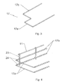
Figure 3 is a perspective of the "U" members (17) in which the horizontal part (17a) is angled. -
Figure 4 is a perspective of a support (23) with tubular bodies (24) for the protection of the "U" members (17), which are located by the vertical part (17b) inside (24). -
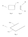
Figure 5 is a front elevation view of the plate (18), with one or more projecting pivots (19). -
Figure 6 is a side elevation view of a plate (18), with one or more projecting pivots (19). - In
Figure 7 , (a) is a perspective of a "U" member (17) of a locking device, for instance a padlock, with the aforementioned "U" member (17) and a locking socket (20), showing (17) and (20) ofFigure 1 . -
Figure 8 is a front elevation view of a support (23) attached to the tray (10) and the rods (11) of the support; in one of the possible embodiments the body of which are concave surfaces (23a) joined to each other by flat surfaces (23b), which may be (23b) alternatively convex surfaces, the role of which is to leave high areas between the "U" members (17) when they are resting in the support (23) object of the invention. -
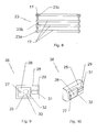
Figure 9 is a front elevation view of a safety screw (38) for immobilising the support (23), and the carrier tray (10) to any point of a vehicle with two or more wheels. -
Figure 10 is a perspective of the safety screw (38), shown in theFigure 9 . -
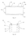
Figure 11 is a top plan view of a support (33) with slots (34) in its smaller side bases (36) for the placement of the "U" members (17). -
Figure 12 is a front elevation view of the support (33) shown in the previous figure. -
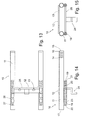
Figure 1 is a top plan view of the device (10), which comprises tubes (11), and in the lower part of (11) tubes (18) and a support (29) for the lock of a padlock. -
Figure 2 is a side elevation view of the device (10), and with a support (29) in the mouth (22) of the tubes (18). -
Figure 3 is a top plan view of the support (29). -
Figure 4 is a side elevation view of the device (10) when the "U" member (33) of the padlock is directed inside the tube (11). -
Figure 5 is a side elevation view of the device (10) when the "U" member (33) of the padlock is inside the tube (11) pushing the plunger (19) and moving the kinematic chain (31). -
Figure 6 is a perspective of the device (10) with the support (29) out of its natural housing, the tubes (12). -
Figure 7 is a perspective of the device (10) with the support (29) partially inside the tubes (12), the lugs (23) coming out of the mouth (22). -
Figure 8 is a perspective of the device (10) with the support (29) totally inside the tubes (18). -
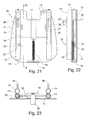
Figure 1 is a lower plan view of the support (10) in the base of which are the tubular elements (13) and (14), and the plate (17) perpendicular to the brace (16) and this to the rods-lugs (15). -
Figure 2 is a side elevation view of the support (10) of the body (11). -
Figure 3 is a front elevation view of the support (10). -
Figure 4 is a section through A-A', according toFigure 1 . -
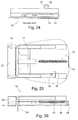
Figure 5 is a lower plan view of the support (10) when the lock box (24) is in the ends of the lugs (15). -
Figure 6 is a side elevation view of the support (10) when it incorporates in the ends of the lugs (15) the lock box (24) of a conventional padlock. - Below is a list of the different parts of the invention, which are indicated in the above drawings with their respective numbers; (10) carrier tray, (11) crossbeam rod, (12) end stop, (13) crossmember rod, (14) flattened area, (15) orifice, (16) vertical part, (17) "U" member, (17 a) base of (17), (17b) vertical parts of "U" member (17), (18) plate, (19) pivots, (20) socket, (21) key, (22) elastic means, (23) support, (23a) concave surface, (24) tubular passageways, (25) plate, (26) cover, (27) bolt, (28) orifice, (29) angled area, (30) screw, (31) rod, (32) non-through hole, (33) support, (34) grooves, (35) lugs, (36) front base of the support (33), (37) clamps, (38) safety screw.
- (10) device, (11) tubes, (12) crossmember plate, (13) holes, (14) spring, (15) plug, (16) end of (11), (17) mouth, (18) tubes, (19) plunger, (20) spring, (21) end of tubes (18), (22) mouth of (18), (23) lugs, (24) angled area, (25) plate, (26) annular recess, (27) pivot, (28) elliptical groove, (29) lock support, (30) levers, (31) kinematic chain, (32) lock of the padlock, (33) "U" member of the padlock.
- (10) support, (11) body, (12) holes, (13-14) tubular elements, (15) rods-lugs, (16) brace, (17) plate, (18) spring, (19) tab, (20) flange, (21) grooves, (22) contact breaker, (23) rod, (24) lock box, (25) lower face of (11), (26) tubular extensions, (27) holes.
- One of the preferred embodiments of the invention, as shown in
Figure 1 , a totally conventional carrier tray (10), comprising generally some crossbeam rods (11), reinforced with crossmember rods (12) also parallel to each other, which is attached (10) to a two-wheeled vehicle, for instance a bicycle, by means of rods (16), which, in one of the embodiments, comprise a horizontal part (16 b), and a vertical part (16a), with a flattened area (14) having (14) an orifice (15), which by means of the corresponding nuts and bolts (not shown in the figures) the carrier tray (10) is secured to the bicycle (or similar vehicle) frame. - The tray (10) is attached to a vehicle of two or more wheels by means of conventional screws (not shown in the figures), so that it allows the fitting of a support (23), as shown in
Figure 1 , which can be made of any material, and has a body formed by the union of concave surfaces (23a) and flat surfaces (23b), or convex surfaces instead of these flat surfaces (23b), as a means of separating one or more "U" members (17) as shown inFigure 1 , these "U" members (17) being part of a locking device such as a padlock comprising this "U" member (17) and a locking socket (20), with its corresponding key (21), when turning it, the vertical parts are immobilised (17b) in the socket (20). - As shown in
Figure 1 , the bodies of the support (23) are hung vertically and immobilise the tray (10) and the crossmember rods (13) by its upper part (23a) or the like, there may be two or more bodies (23) under or over the tray (10) in front of each other to right and left of the same, both in vertical position in which the "U" members (17) will be in standby situation of in horizontal position, resting on the concave surfaces (23a) as shown inFigure 1 , or resting on the tubular passageways (24). - The support bodies (23) can also be hung horizontally from the carrier tray (10), see
Figure 2 , so that in this second horizontal position of the bodies of the support (23), the "U" members (17) would span the wheel of the vehicle between its vertical parts (17b), to which the tray (10) and the support (23) are fitted. - In another of the possible embodiments, the bodies (23) can be joined by means of open tubular passageways (24) as shown in
Figures 1 and4 , which protect the "U." members (17), so that each vertical part (17b) of the "U" member (17) is in horizontal resting position inside said tubular passageways (24) of the body of the support (23), seeFigure 1 , or, in another version, in vertical position, as shown inFigure 2 . - Turning with regard to the tray (10) there is a plate (18), see
Figures 5 and 6 , with pivots (19) in which there are locking sockets (20), as shown inFigure 1 , stopping the "U" members (17) coming out of the bodies (23), or the tubular passageways (24), when not in use. - To avoid damage to the tray (10) and the support (23), the tray (10) is attached to any point of the vehicle by means of a safety screw (38), which, as shown in
Figures 8 and 9 , comprises on a small metal plate (25), and joined to (25) a cover (26) which may turn with regard to the plate (25) thanks to a bolt or rivet (27), which covers the hole (28), through which a screw (30) passes, which secures the safety screw (38) to the tray (10) and to any point of the vehicle, preferably its frame or chassis, when the rod (31) passes through the angled area and fits by deformation into the cover (26), one end of said rod (31) being housed in the non-through hole (32). - In other of the possible embodiments, the safety support for the locking device (33) has a configuration as shown in
Figures 11 and 12 , namely a prismatic body in the lower sides (36) of which have the concave-convex surfaces ofFigure 8 , or flat-concave surfaces, which are no other than these concave surfaces in the form of longitudinal grooves (34) that hold the "U" members (17), their vertical parts (17b) being in the same, secured by means of lugs (35), which avoid it moving in this support (33) once fitted to the grooves (34), having on the front base one or more pivots (19), for immobilising the sockets (20). - The operation of the invention's safety support begins with the placement of the support (23) or (33) on the carrier tray (10), securing it by means of open clamps (37), in the crossbeam or crossmember rods (11-13) of said tray (10), and then place the "U" members (17) in the concave surfaces (23a), or in the tubular passageways (24) or longitudinal grooves (34), securing the "U" members (17) by means of lugs or ribs (35), which avoid the undesired exit of (17), the sockets (20) placed in the pivots (19) on the plate (18), or on the front base (36).
- When the user wishes to immobilise the vehicle of two or more wheels (not shown in the figures), they remove the sockets (20) from the pivots (19), turning the locking keys (21), remove the "U" members from the aforementioned convex surfaces (23a), or from the tubular passageways (24) or grooves (34) and place the "U" members (17) on the wheel, immobilising it to the frame of the vehicle, the seat to the frame, or the frame of the vehicle to an immobile object in the street.
- In other of the preferred embodiments of the invention and as shown in
Figure 1 , improvements are materialised in a device (10) comprising parallel tubes (11), joined by one or more crossmember plates (12), the inside of the tubes (11) having some elastic means such as a spring (14) in the lower part of the tubes (11), other tubes (18) joined to the first (11) by any known method such as welding, bolting or the like. - The tubes (18) have on one of their ends a mouth (17), by which a support (29) for the lock of a padlock is inserted, of a "U"-shape in the ends of which the lock (32) is immobilised.
- As shown in
Figure 2 , the support (29) has some lugs (23) jointed by a perpendicular plate (25), from in its lower part emerges a doubly angled area (24), said support (29) being inserted in the tubes (18) by one of its mouths (22) thanks to an elliptical groove (28), with some plugs (19) in one of the ends of these tubes (18), and other plugs (15) in the ends (16) of the tubes (11). - The lugs (23) have annular recesses (26) on their side surface, as shown in
Figures 2 and3 . - When the user of a vehicle of two or more wheels is driving, the "U" member (33) of the padlock separated from the lock (32), this "U" member (33) is housed in the tubes (11), fitting into them and the "U" member (33) entering by the mouths (17) of (11) pressing against springs (14), these springs (14) being immobilised by the plug (15), at the same time as the movement of the "U" member (33) inside the tubes (11) forces by suitable means to the kinematic chain (31) to the movement of the support (29) outside of the tubes (18), only the lugs (23) projecting through the mouths (22) of (18), on which the lock (32) of the padlock is immobilised on the annular recess (30), as shown in
Figure 5 . - The movement of the support (29) inside the tubes (18) is achieved by means of elliptical grooves (28) and against the action of the springs (20) inside the tubes (18), these springs being immobilised (20) at one end by plugs (19) in the end (21) of (18), so that when the "U" member (33) of the padlock enters the tubes (11), the lugs (23) of the support (29) project, and vice versa when the lock (32) of the padlock is removed from these lugs (23), the "U" member of the padlock projects form the mouths (17) of the device (10), the lugs (23) moving inside the tubes (18), see
Figure 8 . - The kinematic chain (31) has a plunger (19) linked to some levers (30) so that when the "U" member (33) is inserted in the tube (11), the end of (33) pushes the plunger (19) and the levers (30) push the support (29) which goes through the plug (19) compressing the springs (20) and the lugs (23) projecting and the user places the lock (32) in the pivots (27) and annular recess (26). When the lock (33) is removed, the kinematic chain (31) allows pressure of the springs (20) to push the "U" member (33) towards the outside of the tubes (11).
- In other of the preferred embodiments of the invention and as shown in
Figures 1 and5 , the support (10) comprises a plate as a body (11) with some holes (12) in its surface, in the lower face (25) of the body (11) there are attached some tubular elements (13-14), as shown inFigures 3 , so that on the inside of the tubular elements (13) there are some rods with lugs (15), in one of their ends, these rods are joined by a brace (16), as the tubular elements (13) have a groove (21). - The movement of the rods-lugs (15) is done by the user when pressing or pulling a plate (17) using a flange (20), perpendicular (17) to the brace (16) and joined to the end of the plate (17) to a tab (19) by means of a spring (18).
- The operation of the support (10) is as follows: When the user (see
Figure 5 ) releases the rods and lugs (15) from the lock box (24), they move back pushed by the spring (18) and press the rod (23) of the contact breaker (22), then the user removes the "U" member of the padlock from the tubular elements (14), and then blocks the wheels of the vehicle with the "U" member and locks in turn the ends of the "U" member with the lock box (24). - When the user wishes to start the vehicle and turns on the ignition, an electrical cut off or a warning light or acoustic warning will inform the user that it is not possible to start without removing the padlock, separating the "U" member from the lock box (24) of the padlock and placing the "U" member in the tubular elements (14), and then locking them and closing the lock box (24) on the rods and the lugs (15), the lock box (24) stopping the exit of the "U" member from the tubular elements (14).
- The support (10) is designed so it can be attached to the top case of a vehicle of two or more wheels such as a motorcycle or a quad, without causing any inconvenience for fitting the case or other elements onto the vehicle.
- Alternatively the support (10) may incorporate some extensions (26) (as shown in
Figure 3 ) in the tubular elements (13-14) with holes (27), whose purpose is so that the user can secure a helmet by means of a conventional padlock, the "U" member of which pass through the opening of the helmet and the holes (27) are protected form undesired effects. Another option is to place the extensions (26) in the rods-lugs (15) so that they are parallel. - Having sufficiently described this invention using the figures attached, it is easy to understand that any modification may be made to the detail which may be deemed to be appropriate, whenever these changes do not alter the essence of the invention summarised in the following claims.
Claims (10)
- - "SUPPORT FOR LOCKING ELEMENTS" for vehicles of two or more wheels, attaching to any point on the vehicles, such as the chassis, frame, body and similar, comprising one or more locking means such as a padlock with a "U" member the ends of which are immobilised in a locking socket with a key characterised in that the support comprises one or more bodies (23), in which some locking "U" (17) are secured, the locking "U" (17) resting on these bodies (23) or when the locking "U"(17) are housed in tubular passageways (24), attached to these bodies (23) by their ends, the support (23) being attached to a carrier tray (10) by any known means, protecting the "U" members (17) by means of a plate (18) with projecting pivots (19), in which the respective sockets (20), provided with keys (21), are immobilised, being locked the support (23) and the carrier tray (10) to the chassis or frame of the vehicle with a safety screw (38).
- - "SUPPORT FOR LOCKING ELEMENTS" according to the claim 1, characterised in that the body of the support (23) comprises some concave surfaces (23a) joined by flat surfaces (23b).
- - "SUPPORT FOR LOCKING ELEMENTS" according to the preceding claim, characterised in that alternatively the surfaces (23b) of the support (23) will be convex.
- - "SUPPORT FOR LOCKING ELEMENTS" according to the claim 1, characterised in that the concave-convex, or flat concave surfaces (23) are attached to the carrier tray (10) by means of their concave surfaces or by clamps.
- - "SUPPORT FOR LOCKING ELEMENTS" according to the claim 1, characterised in that, alternatively, the body of the support (33) will have a prismatic configuration, the side smaller bases (36) with longitudinal grooves (34), and near one of the ends of these grooves (34) there are some ribs (35) to immobilise the "U" members (17), and one or more pivots (19) on the front base (36).
- - "SUPPORT FOR LOCKING ELEMENTS" according to the claim 1, characterised in that the "U" members (17) are formed by a horizontal base (17a) from which vertical parts (17b) emerge from its ends.
- - "SUPPORT FOR LOCKING ELEMENTS" according to the claims 1 and 6, characterised in that the bases (17a) of the "U" members (17) are not flat.
- - "SUPPORT FOR LOCKING ELEMENTS" according to the claim 1, characterised in that the supports (23) are placed on the right and left of the carrier tray (10), one or more supports (23) can be joined by tubular passageways (24) into which the "U" members (17) are inserted, these tubular passageways (24) have elastic means (22) on their ends.
- - "SUPPORT FOR LOCKING ELEMENTS" according to the claim 8, characterised in that the elastic means (22) are springs.
- - "SUPPORT FOR LOCKING ELEMENTS" according to the claim 1, characterised in that the safety screw (38) comprises a cover (26) on a small metal plate (25), which may turn the cover (26) with regard to the plate (25) thanks to a bolt or rivet (27) jointing them, said cover (26) being concealing the hole (28), through which a screw (30) passes, which secures the safety screw (38) to the tray (10) and to any point of the vehicle, when the rod (31) passes through the angled area and fits by deformation into the cover (26), one end of said rod (31) being housed in the non-through hole (32).
Applications Claiming Priority (4)
| Application Number | Priority Date | Filing Date | Title |
|---|---|---|---|
| ES201131347A ES2406855B1 (en) | 2011-08-02 | 2011-08-02 | SUPPORT FOR CLOSURE ELEMENTS. |
| ES201131690 | 2011-10-21 | ||
| ES201230410 | 2012-03-19 | ||
| PCT/ES2012/070602 WO2013017727A2 (en) | 2011-08-02 | 2012-08-02 | Base for locking elements |
Publications (3)
| Publication Number | Publication Date |
|---|---|
| EP2752359A2 true EP2752359A2 (en) | 2014-07-09 |
| EP2752359A4 EP2752359A4 (en) | 2015-07-15 |
| EP2752359B1 EP2752359B1 (en) | 2020-11-11 |
Family
ID=47629736
Family Applications (1)
| Application Number | Title | Priority Date | Filing Date |
|---|---|---|---|
| EP12819506.2A Active EP2752359B1 (en) | 2011-08-02 | 2012-08-02 | Base for locking elements |
Country Status (3)
| Country | Link |
|---|---|
| EP (1) | EP2752359B1 (en) |
| CN (1) | CN103842241B (en) |
| WO (1) | WO2013017727A2 (en) |
Family Cites Families (11)
| Publication number | Priority date | Publication date | Assignee | Title |
|---|---|---|---|---|
| US4436232A (en) * | 1981-11-16 | 1984-03-13 | Kbl Corporation | Bracket for motorcycle lock |
| NL9002858A (en) * | 1990-12-21 | 1992-07-16 | Gerrit Doppenberg | LOCKING SYSTEM FOR PROTECTING A LIGHT VEHICLE AGAINST THEFT. |
| DE4103295C1 (en) * | 1991-02-04 | 1992-06-11 | Soltenau, Rupert, 8000 Muenchen, De | Luggage carrier on back of bicycle |
| IT1261318B (en) * | 1992-10-28 | 1996-05-14 | Honda Giken Kogyo Kabuschiki K | ANTI-THEFT DEVICE FOR A MOTORCYCLE. |
| JP3315976B2 (en) * | 1992-11-17 | 2002-08-19 | 本田技研工業株式会社 | Vehicle anti-theft device |
| CA2131848A1 (en) * | 1994-05-09 | 1995-11-10 | Paul S. Best | Bicycle rack with integral lock holder |
| US5538167A (en) * | 1995-03-03 | 1996-07-23 | Winner International Royalty Corporation | Holder for securing a bicycle accessory to a bicycle frame |
| FR2765852B1 (en) * | 1997-07-11 | 1999-10-01 | Soffac Sa | ANTI-THEFT SUPPORT FOR A BICYCLE OR SIMILAR VEHICLE |
| US5836491A (en) * | 1997-09-25 | 1998-11-17 | Chuang; Louis | Lock securing device for a bicycle |
| CN201249833Y (en) * | 2008-06-26 | 2009-06-03 | 李国仁 | Detachable luggage rack and anti-theft lock cross bar device structure for two-wheeled vehicle |
| EP2373536B1 (en) * | 2008-09-29 | 2023-12-20 | Hartmut Ortlieb | Fastening system for bags or containers |
-
2012
- 2012-08-02 CN CN201280048473.8A patent/CN103842241B/en not_active Expired - Fee Related
- 2012-08-02 WO PCT/ES2012/070602 patent/WO2013017727A2/en not_active Ceased
- 2012-08-02 EP EP12819506.2A patent/EP2752359B1/en active Active
Also Published As
| Publication number | Publication date |
|---|---|
| EP2752359B1 (en) | 2020-11-11 |
| WO2013017727A3 (en) | 2013-03-21 |
| CN103842241A (en) | 2014-06-04 |
| WO2013017727A2 (en) | 2013-02-07 |
| EP2752359A4 (en) | 2015-07-15 |
| CN103842241B (en) | 2017-06-27 |
Similar Documents
| Publication | Publication Date | Title |
|---|---|---|
| JP7583111B2 (en) | Retaining element and associated retaining device for use in an accumulator - Patents.com | |
| US6623071B2 (en) | Seat fitting structure for motor scooter type vehicle | |
| US5727865A (en) | Detachable trailer light | |
| KR101088550B1 (en) | Car Bike Carrier | |
| US4465196A (en) | Bicycle rack | |
| CN1827451A (en) | Anti-theft device for parking two-wheelers | |
| EP2752359B1 (en) | Base for locking elements | |
| US20080047994A1 (en) | Holding system for transporting two wheeled vehicles | |
| GB2373489A (en) | Locking device for a steering wheel of an automobile | |
| JP3285100B2 (en) | Rear fender of motorcycle | |
| JP5021191B2 (en) | Electrical component removal prevention structure | |
| CN1233703A (en) | Anti-theft devices for motorized two-wheeled vehicles | |
| EP3530495A1 (en) | Removable anti-theft device for coupling | |
| FR2827363A1 (en) | Multi-purpose clip e.g. for securing motor vehicle fuel and brake lines and cables has temporary and permanent fastenings | |
| TWI782613B (en) | Multi-function hook for motorcycle | |
| EP3808638B1 (en) | Motor vehicle comprising an interior device for holding a spare wheel | |
| FR2748444A1 (en) | Antitheft locking device for motorcycle with central prop stand | |
| EP3409569A1 (en) | Bike lock | |
| JPS6227504Y2 (en) | ||
| JP2519869Y2 (en) | Vehicle anti-theft device | |
| JP5902728B2 (en) | Storage for motorcycles | |
| FR2987807A1 (en) | Protection and improvement device for improving aerodynamics of e.g. electric propulsion car, has intermediate careenage extending below central space and carrying-out prolongation of lower face of traction battery block | |
| JP3847067B2 (en) | Rear cowl structure for motorcycles | |
| KR100574248B1 (en) | Car theft double lock using the ground | |
| JP3558468B2 (en) | Storage structure of U-shaped lock for motorcycle |
Legal Events
| Date | Code | Title | Description |
|---|---|---|---|
| PUAI | Public reference made under article 153(3) epc to a published international application that has entered the european phase |
Free format text: ORIGINAL CODE: 0009012 |
|
| 17P | Request for examination filed |
Effective date: 20140227 |
|
| AK | Designated contracting states |
Kind code of ref document: A2 Designated state(s): AL AT BE BG CH CY CZ DE DK EE ES FI FR GB GR HR HU IE IS IT LI LT LU LV MC MK MT NL NO PL PT RO RS SE SI SK SM TR |
|
| DAX | Request for extension of the european patent (deleted) | ||
| A4 | Supplementary search report drawn up and despatched |
Effective date: 20150611 |
|
| RIC1 | Information provided on ipc code assigned before grant |
Ipc: B62H 5/00 20060101AFI20150605BHEP |
|
| 17Q | First examination report despatched |
Effective date: 20160420 |
|
| STAA | Information on the status of an ep patent application or granted ep patent |
Free format text: STATUS: EXAMINATION IS IN PROGRESS |
|
| GRAP | Despatch of communication of intention to grant a patent |
Free format text: ORIGINAL CODE: EPIDOSNIGR1 |
|
| STAA | Information on the status of an ep patent application or granted ep patent |
Free format text: STATUS: GRANT OF PATENT IS INTENDED |
|
| INTG | Intention to grant announced |
Effective date: 20191218 |
|
| GRAJ | Information related to disapproval of communication of intention to grant by the applicant or resumption of examination proceedings by the epo deleted |
Free format text: ORIGINAL CODE: EPIDOSDIGR1 |
|
| STAA | Information on the status of an ep patent application or granted ep patent |
Free format text: STATUS: EXAMINATION IS IN PROGRESS |
|
| INTC | Intention to grant announced (deleted) | ||
| GRAP | Despatch of communication of intention to grant a patent |
Free format text: ORIGINAL CODE: EPIDOSNIGR1 |
|
| STAA | Information on the status of an ep patent application or granted ep patent |
Free format text: STATUS: GRANT OF PATENT IS INTENDED |
|
| INTG | Intention to grant announced |
Effective date: 20200626 |
|
| GRAS | Grant fee paid |
Free format text: ORIGINAL CODE: EPIDOSNIGR3 |
|
| GRAA | (expected) grant |
Free format text: ORIGINAL CODE: 0009210 |
|
| STAA | Information on the status of an ep patent application or granted ep patent |
Free format text: STATUS: THE PATENT HAS BEEN GRANTED |
|
| AK | Designated contracting states |
Kind code of ref document: B1 Designated state(s): AL AT BE BG CH CY CZ DE DK EE ES FI FR GB GR HR HU IE IS IT LI LT LU LV MC MK MT NL NO PL PT RO RS SE SI SK SM TR |
|
| REG | Reference to a national code |
Ref country code: GB Ref legal event code: FG4D |
|
| REG | Reference to a national code |
Ref country code: CH Ref legal event code: EP |
|
| REG | Reference to a national code |
Ref country code: AT Ref legal event code: REF Ref document number: 1333206 Country of ref document: AT Kind code of ref document: T Effective date: 20201115 |
|
| REG | Reference to a national code |
Ref country code: DE Ref legal event code: R096 Ref document number: 602012073214 Country of ref document: DE |
|
| REG | Reference to a national code |
Ref country code: IE Ref legal event code: FG4D |
|
| REG | Reference to a national code |
Ref country code: CH Ref legal event code: NV Representative=s name: BOHEST AG, CH |
|
| REG | Reference to a national code |
Ref country code: NL Ref legal event code: FP |
|
| REG | Reference to a national code |
Ref country code: AT Ref legal event code: MK05 Ref document number: 1333206 Country of ref document: AT Kind code of ref document: T Effective date: 20201111 |
|
| PG25 | Lapsed in a contracting state [announced via postgrant information from national office to epo] |
Ref country code: GR Free format text: LAPSE BECAUSE OF FAILURE TO SUBMIT A TRANSLATION OF THE DESCRIPTION OR TO PAY THE FEE WITHIN THE PRESCRIBED TIME-LIMIT Effective date: 20210212 Ref country code: RS Free format text: LAPSE BECAUSE OF FAILURE TO SUBMIT A TRANSLATION OF THE DESCRIPTION OR TO PAY THE FEE WITHIN THE PRESCRIBED TIME-LIMIT Effective date: 20201111 Ref country code: FI Free format text: LAPSE BECAUSE OF FAILURE TO SUBMIT A TRANSLATION OF THE DESCRIPTION OR TO PAY THE FEE WITHIN THE PRESCRIBED TIME-LIMIT Effective date: 20201111 Ref country code: PT Free format text: LAPSE BECAUSE OF FAILURE TO SUBMIT A TRANSLATION OF THE DESCRIPTION OR TO PAY THE FEE WITHIN THE PRESCRIBED TIME-LIMIT Effective date: 20210311 Ref country code: NO Free format text: LAPSE BECAUSE OF FAILURE TO SUBMIT A TRANSLATION OF THE DESCRIPTION OR TO PAY THE FEE WITHIN THE PRESCRIBED TIME-LIMIT Effective date: 20210211 |
|
| PG25 | Lapsed in a contracting state [announced via postgrant information from national office to epo] |
Ref country code: SE Free format text: LAPSE BECAUSE OF FAILURE TO SUBMIT A TRANSLATION OF THE DESCRIPTION OR TO PAY THE FEE WITHIN THE PRESCRIBED TIME-LIMIT Effective date: 20201111 Ref country code: LV Free format text: LAPSE BECAUSE OF FAILURE TO SUBMIT A TRANSLATION OF THE DESCRIPTION OR TO PAY THE FEE WITHIN THE PRESCRIBED TIME-LIMIT Effective date: 20201111 Ref country code: PL Free format text: LAPSE BECAUSE OF FAILURE TO SUBMIT A TRANSLATION OF THE DESCRIPTION OR TO PAY THE FEE WITHIN THE PRESCRIBED TIME-LIMIT Effective date: 20201111 Ref country code: IS Free format text: LAPSE BECAUSE OF FAILURE TO SUBMIT A TRANSLATION OF THE DESCRIPTION OR TO PAY THE FEE WITHIN THE PRESCRIBED TIME-LIMIT Effective date: 20210311 Ref country code: BG Free format text: LAPSE BECAUSE OF FAILURE TO SUBMIT A TRANSLATION OF THE DESCRIPTION OR TO PAY THE FEE WITHIN THE PRESCRIBED TIME-LIMIT Effective date: 20210211 Ref country code: AT Free format text: LAPSE BECAUSE OF FAILURE TO SUBMIT A TRANSLATION OF THE DESCRIPTION OR TO PAY THE FEE WITHIN THE PRESCRIBED TIME-LIMIT Effective date: 20201111 |
|
| REG | Reference to a national code |
Ref country code: LT Ref legal event code: MG9D |
|
| PG25 | Lapsed in a contracting state [announced via postgrant information from national office to epo] |
Ref country code: HR Free format text: LAPSE BECAUSE OF FAILURE TO SUBMIT A TRANSLATION OF THE DESCRIPTION OR TO PAY THE FEE WITHIN THE PRESCRIBED TIME-LIMIT Effective date: 20201111 |
|
| PG25 | Lapsed in a contracting state [announced via postgrant information from national office to epo] |
Ref country code: SK Free format text: LAPSE BECAUSE OF FAILURE TO SUBMIT A TRANSLATION OF THE DESCRIPTION OR TO PAY THE FEE WITHIN THE PRESCRIBED TIME-LIMIT Effective date: 20201111 Ref country code: RO Free format text: LAPSE BECAUSE OF FAILURE TO SUBMIT A TRANSLATION OF THE DESCRIPTION OR TO PAY THE FEE WITHIN THE PRESCRIBED TIME-LIMIT Effective date: 20201111 Ref country code: LT Free format text: LAPSE BECAUSE OF FAILURE TO SUBMIT A TRANSLATION OF THE DESCRIPTION OR TO PAY THE FEE WITHIN THE PRESCRIBED TIME-LIMIT Effective date: 20201111 Ref country code: EE Free format text: LAPSE BECAUSE OF FAILURE TO SUBMIT A TRANSLATION OF THE DESCRIPTION OR TO PAY THE FEE WITHIN THE PRESCRIBED TIME-LIMIT Effective date: 20201111 Ref country code: CZ Free format text: LAPSE BECAUSE OF FAILURE TO SUBMIT A TRANSLATION OF THE DESCRIPTION OR TO PAY THE FEE WITHIN THE PRESCRIBED TIME-LIMIT Effective date: 20201111 Ref country code: SM Free format text: LAPSE BECAUSE OF FAILURE TO SUBMIT A TRANSLATION OF THE DESCRIPTION OR TO PAY THE FEE WITHIN THE PRESCRIBED TIME-LIMIT Effective date: 20201111 |
|
| REG | Reference to a national code |
Ref country code: DE Ref legal event code: R097 Ref document number: 602012073214 Country of ref document: DE |
|
| PG25 | Lapsed in a contracting state [announced via postgrant information from national office to epo] |
Ref country code: DK Free format text: LAPSE BECAUSE OF FAILURE TO SUBMIT A TRANSLATION OF THE DESCRIPTION OR TO PAY THE FEE WITHIN THE PRESCRIBED TIME-LIMIT Effective date: 20201111 |
|
| PLBE | No opposition filed within time limit |
Free format text: ORIGINAL CODE: 0009261 |
|
| STAA | Information on the status of an ep patent application or granted ep patent |
Free format text: STATUS: NO OPPOSITION FILED WITHIN TIME LIMIT |
|
| 26N | No opposition filed |
Effective date: 20210812 |
|
| PG25 | Lapsed in a contracting state [announced via postgrant information from national office to epo] |
Ref country code: IT Free format text: LAPSE BECAUSE OF FAILURE TO SUBMIT A TRANSLATION OF THE DESCRIPTION OR TO PAY THE FEE WITHIN THE PRESCRIBED TIME-LIMIT Effective date: 20201111 Ref country code: AL Free format text: LAPSE BECAUSE OF FAILURE TO SUBMIT A TRANSLATION OF THE DESCRIPTION OR TO PAY THE FEE WITHIN THE PRESCRIBED TIME-LIMIT Effective date: 20201111 |
|
| PG25 | Lapsed in a contracting state [announced via postgrant information from national office to epo] |
Ref country code: SI Free format text: LAPSE BECAUSE OF FAILURE TO SUBMIT A TRANSLATION OF THE DESCRIPTION OR TO PAY THE FEE WITHIN THE PRESCRIBED TIME-LIMIT Effective date: 20201111 Ref country code: ES Free format text: LAPSE BECAUSE OF FAILURE TO SUBMIT A TRANSLATION OF THE DESCRIPTION OR TO PAY THE FEE WITHIN THE PRESCRIBED TIME-LIMIT Effective date: 20201111 |
|
| REG | Reference to a national code |
Ref country code: DE Ref legal event code: R082 Ref document number: 602012073214 Country of ref document: DE Representative=s name: COHAUSZ & FLORACK PATENT- UND RECHTSANWAELTE P, DE |
|
| PG25 | Lapsed in a contracting state [announced via postgrant information from national office to epo] |
Ref country code: MC Free format text: LAPSE BECAUSE OF FAILURE TO SUBMIT A TRANSLATION OF THE DESCRIPTION OR TO PAY THE FEE WITHIN THE PRESCRIBED TIME-LIMIT Effective date: 20201111 |
|
| PG25 | Lapsed in a contracting state [announced via postgrant information from national office to epo] |
Ref country code: IS Free format text: LAPSE BECAUSE OF FAILURE TO SUBMIT A TRANSLATION OF THE DESCRIPTION OR TO PAY THE FEE WITHIN THE PRESCRIBED TIME-LIMIT Effective date: 20210311 Ref country code: LU Free format text: LAPSE BECAUSE OF NON-PAYMENT OF DUE FEES Effective date: 20210802 |
|
| PG25 | Lapsed in a contracting state [announced via postgrant information from national office to epo] |
Ref country code: HU Free format text: LAPSE BECAUSE OF FAILURE TO SUBMIT A TRANSLATION OF THE DESCRIPTION OR TO PAY THE FEE WITHIN THE PRESCRIBED TIME-LIMIT; INVALID AB INITIO Effective date: 20120802 Ref country code: CY Free format text: LAPSE BECAUSE OF FAILURE TO SUBMIT A TRANSLATION OF THE DESCRIPTION OR TO PAY THE FEE WITHIN THE PRESCRIBED TIME-LIMIT Effective date: 20201111 |
|
| P01 | Opt-out of the competence of the unified patent court (upc) registered |
Effective date: 20230515 |
|
| PGFP | Annual fee paid to national office [announced via postgrant information from national office to epo] |
Ref country code: NL Payment date: 20230826 Year of fee payment: 12 |
|
| PGFP | Annual fee paid to national office [announced via postgrant information from national office to epo] |
Ref country code: IE Payment date: 20230828 Year of fee payment: 12 Ref country code: GB Payment date: 20230828 Year of fee payment: 12 Ref country code: CH Payment date: 20230902 Year of fee payment: 12 |
|
| PGFP | Annual fee paid to national office [announced via postgrant information from national office to epo] |
Ref country code: FR Payment date: 20230825 Year of fee payment: 12 Ref country code: DE Payment date: 20230829 Year of fee payment: 12 Ref country code: BE Payment date: 20230828 Year of fee payment: 12 |
|
| PG25 | Lapsed in a contracting state [announced via postgrant information from national office to epo] |
Ref country code: MK Free format text: LAPSE BECAUSE OF FAILURE TO SUBMIT A TRANSLATION OF THE DESCRIPTION OR TO PAY THE FEE WITHIN THE PRESCRIBED TIME-LIMIT Effective date: 20201111 |
|
| PG25 | Lapsed in a contracting state [announced via postgrant information from national office to epo] |
Ref country code: MT Free format text: LAPSE BECAUSE OF FAILURE TO SUBMIT A TRANSLATION OF THE DESCRIPTION OR TO PAY THE FEE WITHIN THE PRESCRIBED TIME-LIMIT Effective date: 20201111 |
|
| REG | Reference to a national code |
Ref country code: DE Ref legal event code: R119 Ref document number: 602012073214 Country of ref document: DE |
|
| REG | Reference to a national code |
Ref country code: CH Ref legal event code: PL |
|
| REG | Reference to a national code |
Ref country code: NL Ref legal event code: MM Effective date: 20240901 |
|
| GBPC | Gb: european patent ceased through non-payment of renewal fee |
Effective date: 20240802 |
|
| PG25 | Lapsed in a contracting state [announced via postgrant information from national office to epo] |
Ref country code: CH Free format text: LAPSE BECAUSE OF NON-PAYMENT OF DUE FEES Effective date: 20240831 |
|
| PG25 | Lapsed in a contracting state [announced via postgrant information from national office to epo] |
Ref country code: NL Free format text: LAPSE BECAUSE OF NON-PAYMENT OF DUE FEES Effective date: 20240901 |
|
| REG | Reference to a national code |
Ref country code: BE Ref legal event code: MM Effective date: 20240831 |
|
| PG25 | Lapsed in a contracting state [announced via postgrant information from national office to epo] |
Ref country code: DE Free format text: LAPSE BECAUSE OF NON-PAYMENT OF DUE FEES Effective date: 20250301 |
|
| PG25 | Lapsed in a contracting state [announced via postgrant information from national office to epo] |
Ref country code: GB Free format text: LAPSE BECAUSE OF NON-PAYMENT OF DUE FEES Effective date: 20240802 |
|
| PG25 | Lapsed in a contracting state [announced via postgrant information from national office to epo] |
Ref country code: BE Free format text: LAPSE BECAUSE OF NON-PAYMENT OF DUE FEES Effective date: 20240831 |
|
| PG25 | Lapsed in a contracting state [announced via postgrant information from national office to epo] |
Ref country code: FR Free format text: LAPSE BECAUSE OF NON-PAYMENT OF DUE FEES Effective date: 20240831 |
|
| PG25 | Lapsed in a contracting state [announced via postgrant information from national office to epo] |
Ref country code: IE Free format text: LAPSE BECAUSE OF NON-PAYMENT OF DUE FEES Effective date: 20240802 |
|
| PG25 | Lapsed in a contracting state [announced via postgrant information from national office to epo] |
Ref country code: TR Free format text: LAPSE BECAUSE OF FAILURE TO SUBMIT A TRANSLATION OF THE DESCRIPTION OR TO PAY THE FEE WITHIN THE PRESCRIBED TIME-LIMIT Effective date: 20201111 |