EP2752358A1 - Vehicle body top structure - Google Patents
Vehicle body top structure Download PDFInfo
- Publication number
- EP2752358A1 EP2752358A1 EP12826924.8A EP12826924A EP2752358A1 EP 2752358 A1 EP2752358 A1 EP 2752358A1 EP 12826924 A EP12826924 A EP 12826924A EP 2752358 A1 EP2752358 A1 EP 2752358A1
- Authority
- EP
- European Patent Office
- Prior art keywords
- front rail
- vehicle body
- rail
- bracket
- plate portion
- Prior art date
- Legal status (The legal status is an assumption and is not a legal conclusion. Google has not performed a legal analysis and makes no representation as to the accuracy of the status listed.)
- Granted
Links
Images


Classifications
-
- B—PERFORMING OPERATIONS; TRANSPORTING
- B62—LAND VEHICLES FOR TRAVELLING OTHERWISE THAN ON RAILS
- B62D—MOTOR VEHICLES; TRAILERS
- B62D25/00—Superstructure or monocoque structure sub-units; Parts or details thereof not otherwise provided for
- B62D25/06—Fixed roofs
-
- B—PERFORMING OPERATIONS; TRANSPORTING
- B62—LAND VEHICLES FOR TRAVELLING OTHERWISE THAN ON RAILS
- B62D—MOTOR VEHICLES; TRAILERS
- B62D27/00—Connections between superstructure or understructure sub-units
- B62D27/02—Connections between superstructure or understructure sub-units rigid
- B62D27/023—Assembly of structural joints
Definitions
- the present invention relates to a vehicle body upper structure including a vehicle side body and a roof coupled to the side body.
- a vehicle body upper structure of that type includes left and right side bodies and a roof front rail joined to the side bodies.
- the front rail extends laterally and has opposing ends joined to roof side rails of the side bodies.
- a stay is disposed vertically to increase a strength of the roof side rail, such that a force with which a roof panel is pressed against the roof side rail in performing a single-sided spot welding can be transmitted to the stay, as taught in patent literature 1 below.
- the vehicle body upper structure has T-shaped intersections where the laterally extending front rail is joined at its opposing ends to the roof side rails. These intersections make a great contribution to the vehicle body rigidity affecting a NV (noise and vibration) performance of the vehicle body or protection of a passenger compartment (cabin) during roll-over of the vehicle. Recently, it is desired to enhance rigidity and strength of such intersections.
- NV noise and vibration
- Patent Literature 1 JP 2009-40098
- It is an object of the present invention is to provide a vehicle body upper structure designed to increase rigidity and strength of an intersection (T-shaped butt joint) where a side rail and a front rail is welded together with a sufficient weld penetration formed in the front rail even if the front rail is thick.
- a vehicle body upper structure comprising: left and right side rails disposed at upper parts of lateral sides of a vehicle body and extending longitudinally of the vehicle body; and a front rail extending laterally of the vehicle body and having one end joined to the left side rail and an opposite end joined to the right side rail, the front rail having a predetermined width extending longitudinally of the vehicle, wherein at least one of the one end and the opposite end of the front rail includes a thick plate portion and a thin plate portion smaller in thickness than the thick plate portion, the thick plate portion and the thin plate portion being arranged longitudinally of the vehicle body, the thin plate portion being coupled to at least one of the side rails.
- the front rail comprises a plate-shaped front rail upper member having the one end and the opposite end, and a plate-shaped bracket coupled to the one end or the opposite end, the bracket being smaller in thickness than the front rail upper member.
- the one end or the opposite end has a cutout portion or through-hole formed to match the thin plate portion.
- the bracket overlaps the one end or the opposite end and includes an exposure portion exposed through the cutout portion or the through-hole.
- the thin plate portion is defined by the exposure portion.
- the front rail upper member includes a remaining portion where the cutout portion or the though-hole is not formed, the thick plate portion being formed by an overlap between the remaining portion and the bracket.
- each of the side rails comprises a side rail inner member, a side rail stiffener coupled to an outside of the side rail inner member in an overlapping relationship therewith to define a closed cross-sectional shape, and a stay disposed between the side rail inner member and the side rail stiffener.
- the stay includes a stay upper portion, the stay upper portion and the thick plate portion being vertically arranged in an overlapping relationship with each other.
- the front rail further comprises a front rail lower member disposed below the front rail upper member, the front rail upper member having a dimension extending laterally of the vehicle body, the front rail lower member having a dimension extending laterally of the vehicle body, the dimension of the front rail lower member being smaller than the dimension of the front rail upper member.
- the side rails include carrier portions protruding toward a center of a width of the vehicle body and extending longitudinally of the vehicle body, the carrier portions carrying the one end and the opposite end.
- the structure further comprises an extension protruding from each of the side rails toward the center of the width of the vehicle body more than each of the carrying portions, the front rail lower member having a lateral outer end portion carried on the extension such that the extension supports the front rail lower member.
- the bracket is disposed between and coupled to the extension and the front rail upper member in an overlapping relationship with the extension and the front rail upper member.
- the thick plate portion is provided in plural, the plural thick plate portions being arranged longitudinally of the vehicle body, and the thin plate portion is provided in plural, the plural thin plate portions being arranged longitudinally of the vehicle body.
- the front rail upper member includes an upper bead extending longitudinally of the front rail upper member
- the bracket includes a bracket bead extending along the upper bead, the bracket bead and the upper bead being arranged vertically in an overlapping relationship with each other.
- the upper bead extends toward the thick plate portion.
- the thin plate portion is so thin that the thin plate portion is welded to the side rail with a sufficient weld penetration. That is, when the thin plate portion is welded to the side rail in an overlapping relationship therewith by single-sided spot welding, an insufficient weld penetration can be prevented without reducing the weld strength between the thin plate portion and the side rail, unlike welding of the thick plate portion.
- the front rail includes the front rail upper member having the cutout portion or the through-hole formed in each of the one end and the opposite end.
- the thick plate portion and the thin plate portion are easy to form because the thick plate portion and the thin plate portion are formed in a simple structure formed just by placing the bracket of thin steel plate on each of the one end and the opposite end and coupling the bracket to each of the one end and the opposite end.
- the thickness of each of the thick plate portion and the thin plate portion can be simply set.
- the front rail upper member and the bracket overlap each other and are coupled together to form the thick plate portion.
- the thick plate portion defined by these two members coupled together extends to and overlaps the side rail such that the rigidity and strength of the intersection (T-shaped butt joint) of the side rail and the front rail is increased.
- the stay is arranged such that a downwardly-directed pressing force exerted by a spot gun on a vicinity of the thick plate portion to perform spot welding (single-sided spot welding) on the vicinity can be transmitted from the thick plate portion to the stay. That is, since the stay bears the downwardly-directed force pressing the one end and/or the opposite end having the thick plate portion, the side rail does not deform even when the relatively large pressing force is transmitted to the side rail.
- the single-sided spot wielding can be performed on an increased number of points to thereby firmly couple the side rail and the front rail together so as to increase the rigidity and strength of the intersection (T-shaped butt joint) of the side rail and the front rail.
- the bracket is disposed between the extension and the front rail upper member, and the bracket is coupled to the extension and the front rail upper member in an overlapping relationship with the extension and the front rail upper member, thereby increasing a coupling strength between the bracket and each of the extension and the front rail upper member.
- These three members overlap one another and are coupled together to form a "three-layered coupled part" having an increased rigidity and strength. As a result, the rigidity and strength of the intersection (T-shaped butt joint) of the side rail and the front rail can be increased.
- the thick plate portion is provided in plural and the plural thick plate portions are arranged longitudinally of the vehicle body.
- the thin plate portion is provided in plural and the plural thin plate portions are arranged longitudinally of the vehicle body.
- the thin plate portions have welds at which the one end and the opposite end of the front rail are welded to the side rail. These welds are arranged at predetermined intervals to increase coupling between the side rail and the front rail.
- the plural thick plate portions are arranged at predetermined intervals. That is to say, the thick plate portion is provided for increasing the rigidity and strength, and such a portion for increasing the rigidity and strength is provided in plural at the predetermined intervals. As a result, the coupling between the side rail and the front rail can be increased to thereby increase the rigidity and strength of the intersection (T-shaped butt joint) of the side rail and the front rail.
- the front rail upper member includes the upper bead extending longitudinally of the front rail upper member, and the bracket includes the bracket bead extending along the upper bead.
- the bracket bead and the upper bead are arranged vertically in an overlapping relationship with each other.
- the upper bead extends toward the thick plate portion, a load can be smoothly transmitted from the upper bead to the thick plate portion, such that the load (stress) on the upper bead can be reduced by this smooth transmission of the load to the thick plate portion.
- the rigidity and strength of the front rail can be increased.
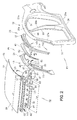
- a vehicle body upper structure 13 is employed in a vehicle body 12.
- the vehicle body 12 includes left and right sides (side bodies) 16, 17 defining left and right walls of a vehicle compartment 15, and a roof 18.
- the roof 18 includes a roof panel 21, and a front rail assembly 22 defining a front portion of the roof 18.
- the roof panel 21 has roof panel side portions 23, 24 joined to the left and right sides 16, 17.
- the vehicle body lateral sides 16, 17 include lower side sills 26, front pillars 27, center pillars 28, rear pillars 31 and upper side rails 32.
- the side sills 26, the front pillars 27, the center pillars 28, the rear pillars 31, and the side rails 32 have side sill outer panels 26a, front pillar outer panels 27a, center pillar outer panels 28a, rear pillar outer panels 31a, and side rail outer portions 32a, respectively, all of which are integral with one another to form side outer panels 34.
- Each of the side rails 32 includes a side rail inner member 36, the side rail outer portion 32a, a side rail stiffener 37, an inner reinforcement member 38, and an outer reinforcement member 41, as shown in Figs. 2 , 3 , 5 and 6 . It is noted that the side rail outer portion 32a, the side rail stiffener 37 and the outer reinforcement member 41 are removed from Fig. 6 .
- the side rail inner member 36 has upper and lower flange portions 42, 43 joined through the side rail stiffener 37 to upper and lower flange portions 45, 46, respectively.
- the side rail inner member 36 and the side rail stiffener 37 define a closed cross-sectional shape having a hollow space 47 ( Fig. 4 ). Within the hollow space 47 are disposed the inner reinforcement member 38, the outer reinforcement member 41, a front stay 51 and a rear stay 52.
- the left and right sides 16, 17 are symmetrically arranged about a center of a width of the vehicle body 12.
- the roof 18 has a front one end portion 54 ( Fig. 1 ) joined to the left side 16, and a front opposite end portion ( Fig. 1 ) joined to the right side 17.
- the vehicle body upper structure 13 includes the left and right side rails 32 disposed at upper parts of the left and right sides 16, 17 and extending longitudinally of the vehicle body 12.
- the vehicle body upper structure 13 also includes the front rail 22 extending laterally of the vehicle body and having one end 57 joined to the left side rail 32 and an opposite end 58 joined to the right side rail 32.
- the front rail 22 has a predetermined width extending longitudinally of the vehicle body 12.
- At least one of the one end 57 and the opposite end 58 has thick plate portions 61, 62 and thin plate portions 63, 64, 65 smaller in thickness than the thick plate portions 61, 62.
- the thick plate portions 61, 62 and the thin plate portions 63, 64, 65 are arranged longitudinally of the vehicle body 12.
- the thin plate portions 63, 64, 65 are joined to the left and right side rails 32.
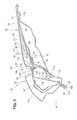
- the front rail 22 includes a plate-shaped front rail upper member 67 having the one end 57 and the opposite end 58, and a plate-shaped bracket 68 coupled to the one end 57 or the opposite end 58.
- the bracket 68 has a thickness (tb) smaller than a thickness tu ( Figs. 3 and 9 ) of the front rail upper member 67.
- the one end 57 or the opposite end 58 of the front rail upper member 67 includes first, second and third cutout portions 71, 72, 73 matching the thin plate portions 63, 64, 65, respectively.
- the bracket 68 overlaps the one end 57 or the opposite end 58 and includes first, third and fifth welded portions 142, 144, 146 which are exposed through the first, second and third cutout portions 71, 72, 73, respectively.
- the thin plate portions 63, 64, 65 define the first, third and fifth welded portions 142, 144, 146.
- the front rail upper member 67 includes remaining portions 75, 76 where the first, second and third cutout portions 71, 72, 73 are formed. These remaining portions 75, 76 and the bracket 68 overlap to thereby form the thick plate portions 61, 62.
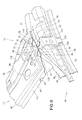
- the side rail 32 includes the side rail inner member 36, the side rail stiffener 37 brought into an overlapping relationship with the side rail inner member 36 (in a direction of an arrow a1) and coupled to an outside of the side rail inner member 36 to define a closed cross-sectional shape, and a front stay 51 disposed between the side rail inner member 36 and the side rail stiffener 37.
- the front stay 51 includes a stay upper portion 77, and the stay upper portion 77 and the thick plate portion 61 are vertically arranged in an overlapping relationship with each other.
- the front rail 22 includes a front rail lower member 78 disposed below the front rail upper member 67.
- the front rail lower member 78 has a length Lw defined as a dimension extending laterally of the vehicle body 12.
- the length Lw is smaller than a length Lu of the front rail upper member 67.
- the side rails 32 have carrier portions 81 extending longitudinally of the vehicle body 12 and projecting toward the center of the width of the vehicle body 12. The carrier portions 81 carry the one end 57 and the opposite end 58 thereon.
- An extension 91 extends from the side rail 32 toward the center of the width of the vehicle body 12 more than the carrier portion 81.
- the front rail lower member 78 includes a lateral outer end portion 82 having front and rear flanges 84, 85 carried on front and rear flange portions 87, 88 ( Fig. 7 ) of the extension 91, such that the front rail lower member 78 is supported on the extension 91.
- the bracket 68 is disposed between the extension 91 and the front rail upper member 67 and coupled at welds 93 to the front rail upper member 67 and the rear flange portion 88 of the extension 91 in an overlapping relationship with the front rail upper member 67 and the rear flange portion 88, as shown in Figs. 5 , 7 and 8 .
- the thick plate portions 61, 62 are arranged longitudinally of the vehicle body 12, and the thin plate portions 63, 64, 65 are arranged longitudinally of the vehicle body 12.
- the front rail upper member 67 includes an upper bead 95 extending laterally of the vehicle body 12, i.e., longitudinally of a body 94 of the front rail upper member 67.
- the bracket 68 includes a bracket bead 96 extending along the upper bead 95, and the bracket 68 and the upper bead 95 are arranged vertically in an overlapping relationship with each other.
- the upper bead 95 extends toward the thick plate portion 61, as indicated by an arrow a3 of Fig. 6 .
- the vehicle body upper structure 13 includes an uncompleted side rail 98 and the front rail 22 of the roof 18.
- the uncompleted side rail 98 is an assembly to be joined to the roof panel 21 and the side rail outer portion 32a.
- the uncompleted side rail 98 includes an upper side rail inner assembly 101 to be attached to the roof 18, and a lower side rail inner assembly 102 extending downwardly and contiguous with the upper side rail inner assembly 101.
- the uncompleted side rail 98 includes the side rail inner member 36, the front stay 51, the rear stay 52, the inner reinforcement member 38, the outer reinforcement member 41, the side rail stiffener 37, and the extension 91 joined to the side rail inner member 36 and the roof 18.
- the bracket 68 is not included in the uncompleted side rail 98.
- the side rail stiffener 37 is joined to the side rail inner member 36. More specifically, the side rail stiffener 37 has an upper flange 37a and a lower flange 37b overlapping and joined to the upper flange portion 42 and the lower flange portion 43, respectively.
- the inner reinforcement member 38 overlaps and is joined to the side rail inner member 36.
- the outer reinforcement member 41 overlaps and is joined to the side rail stiffener 37. As shown in Fig. 3 , the front stay 51 is disposed between the inner reinforcement member 38 and the outer reinforcement member 41.
- the front stay 51 is L-shaped and has the stay upper portion 77 carried on the side rail inner member 36.
- the front stay 51 also has a roof backup 106 contiguous with the stay upper portion 77 and contacting an inner surface of the side rail stiffener 37.
- the front stay 51 includes a vertical portion 107 extending downwardly from the roof backup 106.
- the front stay 51 further includes a stay lower portion 108 contiguous with the vertical portion 107.
- the stay lower portion 108 and the stay upper portion 77 are sandwiched between and joined to the side rail inner member 36 and the side rail stiffener 37.
- the stay upper portion 77 overlaps and is joined through the side rail stiffener 37 to the left one end 57 of the laterally extending front rail 22, as shown in Fig. 3 .
- the right end 58 is joined through the side rail stiffener 37 to the stay upper portion 77 in an overlapping relationship with the stay upper portion 77.
- the ends 57, 58 of the front rail 22 are carried on and coupled to the extension 91 of the uncompleted side rail 98.
- the extension 91 has one end 111 joined to the side rail inner member 36, and an opposite end 112 joined to the front rail 22, as shown in Figs. 2 to 4 and 6 to 8.
- the extension 91 includes a bottom portion 114 formed from the side rail joined portion 111 to the front rail joined portion 112.
- the extension 91 further includes front and rear side portions 115, 116 contiguous with the bottom portion 114.
- the front side portion 115 defines the front flange portion 87
- the rear side portion 116 defines the rear flange portion 88.
- the front flange portion 87 and the rear flange portion 88 are joined to the front flange 84 and the rear flange 85 of the front rail lower member 78.
- the extension 91 is located at an intersection 121 ( Fig. 3 ) where the uncompleted side rail 98 and the front rail assembly 22 intersect in the form of a T-shaped butt joint.
- the front rail assembly 22 includes the front rail upper member 67, the front rail lower member 78, the bracket 68 and a rail reinforcement member 123.
- the front rail upper member 67 extends from the left side rail inner member 36 to the right side rail inner member 36 with the one end 57 and the opposite end 58 being joined to the one end 57 and the opposite end 58, respectively.
- the front rail upper member 67 includes a top portion 125, an upper front wall 126 and an upper rear wall 127 which define a U-shaped closed cross-sectional shape, as shown in Fig. 8 .
- the upper front wall 126 and the upper rear wall 127 are contiguous with a front upper flange portion 117 and a rear upper flange portion 118, respectively.
- the one end 57 and the opposite end 58 are in a generally symmetrical relationship with each other, and hence discussion below is made as to the one end 57 only.
- the one end 57 of the front rail upper member 67 includes a sidewall 132 contiguous with the top portion 125 ( Fig. 8 ), and one end flange 132 contiguous with the sidewall 132.
- the one end flange 132 defines the first cutout portion 71, a central weld 133, the second cutout portion 72, a rear end weld 134 and the third cutout portion 73 which are arranged in order from a front side of the front rail upper member 67.
- the first cutout portion 71 and the central weld 133 are located at a predetermined interval p1
- the central weld 133 and the second cutout portion 72 are located at a predetermined interval p2
- the second cutout portion 72 and the rear end weld 134 are located at a predetermined interval p3
- the rear end weld 134 and the third cutout portion 73 are located at a predetermined interval p4.
- the one end flange 132 extends along the side rail inner member 36, and the central weld 133 is located centrally of the one end flange 132.
- the first cutout portion 71 is located forwardly of the central weld 133
- the second cutout portion 72 is located rearwardly of the central weld 133.
- the rear end weld 134 is spaced rearwardly from the central weld 133 by a predetermined distance.
- the third cutout portion 73 is located rearwardly of the rear end weld 134.
- the front rail upper member 67 has the upper bead 95 formed on the top portion 125.
- the upper bead 95 is a channel recessed toward the front rail lower member 78, and extends along a longitudinal center of the front rail upper member 67.
- An extension line 136 ( Fig. 5 ) extending from the upper bead 95 passes through or near the central weld 133, when viewed from above ( Figs. 5 and 6 ).
- the front rail upper member 67 has the length Lu ( Fig. 2 ) larger than the length Lw of the front rail lower member 78.
- the front rail upper member 67 has the thickness tu ( Fig. 3 ) along the entire length from the one end 57 to the opposite end 58. Attached to the one end 57 is the bracket 68 having a thickness smaller than the thickness tu.
- the bracket 68 includes a bracket bead 96 formed centrally thereof, another bracket bead 138 formed along the bracket bead 96, and a remaining portion 141 made of a blank material.
- the remaining portion 141 of the blank material includes the exposed first welded portion 142, a second welded portion 143, the exposed third welded portion 144, a fourth welded portion 145 and the exposed fifth welded portion 146 which are arranged at predetermined intervals in order from a front side of the remaining portion 141. That is, the first welded portion 142, the third welded portion 144, and the fifth welded portion 146 are defined by the thin plate portions 63, 64, 65 of the front rail (front rail assembly) 22.
- the front rail lower member 78 is U-shaped in cross-section.
- the rail reinforcement member 123 is disposed between the front rail lower member 78 and the front rail upper member 67.
- the rail reinforcement member 123 is located at opposing ends of the lower rail lower member 78 and sandwiched between and joined to the front and rear flanges 84, 85 and the front and rear upper flange portions 117, 118.
- the uncompleted side rail 98 and the front rail assembly 22 are provided in advance.
- the side outer panel 34 is joined to the uncompleted side rail 98 to thereby complete the side rail 32.
- the front rail assembly 22 is joined to the completed side rail 32.
- the roof panel 21 is placed thereon.
- the inner reinforcement member 38 is joined to the side rail inner member 36 by spot-welding (not shown).
- the outer reinforcement member 41 is joined to the side rail stiffener 37 by spot-welding (not shown).
- the side rail stiffener 37 is joined to the side rail inner member 36.
- the front stay 51 and the rear stay 52 are sandwiched between the upper flange portion 42 and the upper flange 37a and between the lower flange portion 43 and the lower flange 37b.
- the upper flange 42 and the upper flange 37a are joined together by spot-welding (not shown).
- the lower flange portion 43 and the lower flange 37b are joined together by spot-welding (not shown).
- the one end (side rail joined portion) 111 ( Fig. 7 ) of the extension 91 is joined to the side rail inner member 36 to thereby form the uncompleted side rail 98.
- the bracket 68 is attached to the front rail upper member 67 ( Fig. 3 ).
- the bracket 68 is spot-welded at a central joined portion 151 ( Fig. 5 ) and a front joined portion 152 to the top portion 125 of the front rail upper member 67, such that welds 153, 154 are formed.
- the second welded portion 143 ( Fig. 3 ) and the fourth welded portion 145 ( Fig. 7 ) of the bracket 68 are spot-welded to the central weld 133 and the rear end weld 134 of the one end flange 132 of the front rail upper member 67, such that welds 155 ( Fig. 5 ) are formed.
- the thick plate portion 61 ( Fig. 3 ) is formed by the second welded portion 143 of the bracket 68 overlapping the central weld 133 of the front rail upper member 67.
- the thick plate portion 62 is formed by the fourth welded portion 145 of the bracket 68 overlapping the rear end weld 134 of the front rail upper member 67.
- the thin plate portions 63, 64, 65 are the first, third and fifth welded portions 142, 144, 146 of the bracket 68.
- the side outer panel 34 is joined to the uncompleted side rail 98, thereby completing the side rail 32.
- the front rail 22 is carried on and joined to the completed side rail 32.
- the lateral outer end portion 82 of the front rail lower member 78 is carried on the front rail joined portion 112 defining the opposite end of the extension 91, and each of the one end 57 and the opposite end 58 of the front rail upper member 67 is placed over the upper flange 37a of the side rail stiffener 37 and the upper flange portion 42 of the side rail inner member 36.
- the upper flange portion 42 of the side rail inner member 36, the upper flange 37a of the side rail stiffener 37 and each of the first, third and fifth welded portions 142, 144, 146 overlap one another and are joined together by single-sided spot welding to thereby form welds 156.
- the rear upper flange portion 118 of the front rail upper member 67, a rear joined portion 158 of the bracket 68, and the rear flange portion 88 of the extension 91 overlap one another and are spot-welded together to thereby form the welds 93. That is, the bracket 68, the extension 91 and the front rail upper member 67 overlap and are joined to one another to thereby form a "three-layered coupled part" ( Fig. 8 ).
- the front and rear flange portions 87, 88 of the extension 91 are spot-welded at welds 161 to the front and rear upper flange portions 117, 118 of the front rail upper member 67.
- roof panel 21 is carried on and joined to the side rail 32. More specifically, a roof flange portion 163 ( Fig. 3 ) of the roof panel 21, the upper flange portion 45 of the side rail outer portion 32a, and the upper flange 37a of the side rail stiffener 37 overlap one another, and are pressed against the front and rear stays 51, 52 and coupled to the stays 51, 52 by single-sided spot-welding to thereby form welds 164.
- the vehicle body upper structure 13 has the advantage that the front rail 22 is sufficiently welded to the side rail 32 by means of the thin plate portions 63, 64, 65 (the first, third and fifth welded portions 142, 144, 146).
- the front thick plate portion next to the thin plate portions 64, 65 (the third welded portion 144 ( Fig. 7 ) and the fifth welded portion 146) or the rear thick plate portion next to the thin plate portions 63, 64 (the first welded portion 142 and the third welded portion 144) extends to the side rail 32 (the assembly of the side rail inner member 36 and the side rail stiffener 37 joined to the side rail inner member 36) in an overlapping relationship with the side rail 32, the intersection (T-shaped butt joint) 121 where the side rail 32 and the front rail 22 intersect can have increased rigidity and strength.
- a spot gun 166 ( Fig. 3 ) exerts a downwardly-directed pressing force on vicinities of the thick plate portions 61, 62, i.e., on the roof panel 21 to perform single-sided spot welding on the roof panel 21, the force can be transmitted from the thick plate portions 61, 62 to the front stay 51, as indicated by an arrow a4 (see Fig. 6 , too) and an arrow a5.
- a vehicle body upper structure 13B in an embodiment 2 is discussed with reference to Fig. 10.
- Fig. 10 corresponds to Fig. 9 .
- a discussion of the same elements of the vehicle body upper structure 13B as those of the vehicle body upper structure 13 in the embodiment 1 shown in Figs. 1 to 9 is omitted.
- the vehicle body upper structure 13B in the embodiment 2 includes a front rail upper member 67B having thick plate portions 61B, 62B and thin plate portions 63B, 64B, 65B formed integrally with one another. More specifically, the front rail upper member 67B is made of a thick plate material, and the thick plate material is partially subjected to a machining operation (cutting or grinding) or recessed (through a plastic working), such that the thin plate portions 63B, 64B, 65B are formed on one end and an opposite end of the front rail upper member 67B. In this case, the thick plate portions 61B, 62B are portions which have not been subjected to the machining operation (cutting or grinding) or recessed (through the plastic working).
- the vehicle body upper structure 13B in the embodiment 2 has the same advantages as those of the vehicle body upper structure 13 in the embodiment 1.
- the vehicle body upper structure 13B in the embodiment 2 does not employ the bracket 68 overlapping the front rail upper member 67 to form the thick plate portions 61, 62 in the embodiment 1.
- the thick plate portions 61B, 62B and the thin plate portions 63B, 64B, 65B are easy to manufacture because it is not necessary to perform a plastic working, a maintenance operation and a welding operation on the bracket 68.
- FIG. 11 corresponds to Fig. 5 .
- a discussion of the same elements of the vehicle body upper structure 13C as those of the vehicle body upper structure 13 in the embodiment 1 shown in Figs. 1 to 9 is omitted.
- the vehicle body upper structure 13C in the embodiment 3 includes a front rail upper member 67C having through-holes 168 at one end 57C or an opposite end located in a symmetrical relationship with the one end 57C.
- the through-holes 168 match thin plate portions 63C, 64C.
- the bracket 68 overlaps the one end 57C or the opposite end, and includes exposure portions 63C, 64C exposed through the through-holes 168.
- the front rail upper member 67C includes remaining portions 75C, 76C where the through-holes 168 are not formed.
- the thick plate portions 61C, 62C are formed by an overlap between the remaining portions 75C, 76C and the bracket 68.
- the through-holes 168 have the least sizes allowing spot-welding to be performed on the thick plate portions 61C, 62C.
- the vehicle body upper structure 13C in the embodiment 3 has the same advantages as those of the vehicle body upper structure 13 in the embodiment 1.
- an edge 169 continuously extends to facilitate dispersion of a load applied thereto as well as to increase rigidity and strength of a T-shaped butt joint 121C.
- the vehicle body upper structure 13 may have a plurality of brackets 68 stacked together to form the thick plate portions 61, 62 although the thick portions 61, 62 are formed by an overlap between the front rail upper member 67 and the single bracket 68.
- the present invention is suitable for use in an automobile.
Landscapes
- Engineering & Computer Science (AREA)
- Chemical & Material Sciences (AREA)
- Combustion & Propulsion (AREA)
- Transportation (AREA)
- Mechanical Engineering (AREA)
- Body Structure For Vehicles (AREA)
Abstract
Description
- The present invention relates to a vehicle body upper structure including a vehicle side body and a roof coupled to the side body.
- A vehicle body upper structure of that type includes left and right side bodies and a roof front rail joined to the side bodies. The front rail extends laterally and has opposing ends joined to roof side rails of the side bodies. Within each of the roof side rails to which the opposing ends of the front rail are joined, a stay is disposed vertically to increase a strength of the roof side rail, such that a force with which a roof panel is pressed against the roof side rail in performing a single-sided spot welding can be transmitted to the stay, as taught in patent literature 1 below.
- The vehicle body upper structure has T-shaped intersections where the laterally extending front rail is joined at its opposing ends to the roof side rails. These intersections make a great contribution to the vehicle body rigidity affecting a NV (noise and vibration) performance of the vehicle body or protection of a passenger compartment (cabin) during roll-over of the vehicle. Recently, it is desired to enhance rigidity and strength of such intersections.
- The stay of the vehicle body upper structure of patent literature 1, which is adapted to receive and deliver the pressing force of the roof panel exerted on the roof side rail in performing the single-side spot welding, contributes to the improvement in the NV performance or protection of the cabin during the roll-over of the vehicle. Meanwhile, the intersections of the vehicle body upper structure need to have a higher strength. To increase the strength of the intersections, it is thought that the front rail is required to be thick. However, when the thick front rail is joined to the roof side rail by single-sided spot welding, an insufficient weld penetration is formed in the thick front rail. As a result, the weld strength between the thick front rail and the roof side rail is undesirably low.
- Patent Literature 1:
JP 2009-40098 - It is an object of the present invention is to provide a vehicle body upper structure designed to increase rigidity and strength of an intersection (T-shaped butt joint) where a side rail and a front rail is welded together with a sufficient weld penetration formed in the front rail even if the front rail is thick.
- According to one aspect of the present invention, as defined in claim 1, there is provided a vehicle body upper structure comprising: left and right side rails disposed at upper parts of lateral sides of a vehicle body and extending longitudinally of the vehicle body; and a front rail extending laterally of the vehicle body and having one end joined to the left side rail and an opposite end joined to the right side rail, the front rail having a predetermined width extending longitudinally of the vehicle, wherein at least one of the one end and the opposite end of the front rail includes a thick plate portion and a thin plate portion smaller in thickness than the thick plate portion, the thick plate portion and the thin plate portion being arranged longitudinally of the vehicle body, the thin plate portion being coupled to at least one of the side rails.
- Preferably, as defined in claim 2, the front rail comprises a plate-shaped front rail upper member having the one end and the opposite end, and a plate-shaped bracket coupled to the one end or the opposite end, the bracket being smaller in thickness than the front rail upper member. The one end or the opposite end has a cutout portion or through-hole formed to match the thin plate portion. The bracket overlaps the one end or the opposite end and includes an exposure portion exposed through the cutout portion or the through-hole. The thin plate portion is defined by the exposure portion. The front rail upper member includes a remaining portion where the cutout portion or the though-hole is not formed, the thick plate portion being formed by an overlap between the remaining portion and the bracket.
- Preferably, as defined in claim 3, each of the side rails comprises a side rail inner member, a side rail stiffener coupled to an outside of the side rail inner member in an overlapping relationship therewith to define a closed cross-sectional shape, and a stay disposed between the side rail inner member and the side rail stiffener. The stay includes a stay upper portion, the stay upper portion and the thick plate portion being vertically arranged in an overlapping relationship with each other.
- Preferably, as defined in claim 4, the front rail further comprises a front rail lower member disposed below the front rail upper member, the front rail upper member having a dimension extending laterally of the vehicle body, the front rail lower member having a dimension extending laterally of the vehicle body, the dimension of the front rail lower member being smaller than the dimension of the front rail upper member. The side rails include carrier portions protruding toward a center of a width of the vehicle body and extending longitudinally of the vehicle body, the carrier portions carrying the one end and the opposite end. The structure further comprises an extension protruding from each of the side rails toward the center of the width of the vehicle body more than each of the carrying portions, the front rail lower member having a lateral outer end portion carried on the extension such that the extension supports the front rail lower member. The bracket is disposed between and coupled to the extension and the front rail upper member in an overlapping relationship with the extension and the front rail upper member.
- Preferably, as defined in claim 5, the thick plate portion is provided in plural, the plural thick plate portions being arranged longitudinally of the vehicle body, and the thin plate portion is provided in plural, the plural thin plate portions being arranged longitudinally of the vehicle body.
- Preferably, as defined in claim 6, the front rail upper member includes an upper bead extending longitudinally of the front rail upper member, and the bracket includes a bracket bead extending along the upper bead, the bracket bead and the upper bead being arranged vertically in an overlapping relationship with each other.
- Preferably, as defined in claim 7, the upper bead extends toward the thick plate portion.
- As defined in claim 1, the thin plate portion is so thin that the thin plate portion is welded to the side rail with a sufficient weld penetration. That is, when the thin plate portion is welded to the side rail in an overlapping relationship therewith by single-sided spot welding, an insufficient weld penetration can be prevented without reducing the weld strength between the thin plate portion and the side rail, unlike welding of the thick plate portion.
- In addition, rigidity and strength of an intersection (T-shaped butt joint) where the side rail and the front rail intersect can be increased by the thick plate portion extending to and overlapping the side rail. As a result, a NV performance of the vehicle body and a roll-over performance (i.e., a cabin protection performance during a roll-over of the vehicle) can be improved.
- As defined in claim 2, the front rail includes the front rail upper member having the cutout portion or the through-hole formed in each of the one end and the opposite end. The thick plate portion and the thin plate portion are easy to form because the thick plate portion and the thin plate portion are formed in a simple structure formed just by placing the bracket of thin steel plate on each of the one end and the opposite end and coupling the bracket to each of the one end and the opposite end. The thickness of each of the thick plate portion and the thin plate portion can be simply set.
- The front rail upper member and the bracket overlap each other and are coupled together to form the thick plate portion. The thick plate portion defined by these two members coupled together extends to and overlaps the side rail such that the rigidity and strength of the intersection (T-shaped butt joint) of the side rail and the front rail is increased.
- Regarding claim 3, the stay is arranged such that a downwardly-directed pressing force exerted by a spot gun on a vicinity of the thick plate portion to perform spot welding (single-sided spot welding) on the vicinity can be transmitted from the thick plate portion to the stay. That is, since the stay bears the downwardly-directed force pressing the one end and/or the opposite end having the thick plate portion, the side rail does not deform even when the relatively large pressing force is transmitted to the side rail. Thus, the single-sided spot wielding can be performed on an increased number of points to thereby firmly couple the side rail and the front rail together so as to increase the rigidity and strength of the intersection (T-shaped butt joint) of the side rail and the front rail.
- As defined in claim 4, the bracket is disposed between the extension and the front rail upper member, and the bracket is coupled to the extension and the front rail upper member in an overlapping relationship with the extension and the front rail upper member, thereby increasing a coupling strength between the bracket and each of the extension and the front rail upper member. These three members overlap one another and are coupled together to form a "three-layered coupled part" having an increased rigidity and strength. As a result, the rigidity and strength of the intersection (T-shaped butt joint) of the side rail and the front rail can be increased.
- As defined in claim 5, the thick plate portion is provided in plural and the plural thick plate portions are arranged longitudinally of the vehicle body. The thin plate portion is provided in plural and the plural thin plate portions are arranged longitudinally of the vehicle body. The thin plate portions have welds at which the one end and the opposite end of the front rail are welded to the side rail. These welds are arranged at predetermined intervals to increase coupling between the side rail and the front rail. The plural thick plate portions are arranged at predetermined intervals. That is to say, the thick plate portion is provided for increasing the rigidity and strength, and such a portion for increasing the rigidity and strength is provided in plural at the predetermined intervals. As a result, the coupling between the side rail and the front rail can be increased to thereby increase the rigidity and strength of the intersection (T-shaped butt joint) of the side rail and the front rail.
- As defined in claim 6, the front rail upper member includes the upper bead extending longitudinally of the front rail upper member, and the bracket includes the bracket bead extending along the upper bead. The bracket bead and the upper bead are arranged vertically in an overlapping relationship with each other. Thus, it becomes possible to disperse a load into the bracket bead and increase the rigidity and strength of the front rail.
- As defined in claim 7, since the upper bead extends toward the thick plate portion, a load can be smoothly transmitted from the upper bead to the thick plate portion, such that the load (stress) on the upper bead can be reduced by this smooth transmission of the load to the thick plate portion. As a result, the rigidity and strength of the front rail can be increased.
-
-
Fig. 1 is a perspective view of a vehicle including a vehicle body upper structure in a first embodiment of the present invention; -
Fig. 2 is an exploded view of the vehicle body shown inFig. 1 ; -
Fig. 3 is a cross-sectional view taken along line 3-3 ofFig. 1 ; -
Fig. 4 is a cross-sectional view taken along line 4-4 ofFig. 1 ; -
Fig. 5 is a perspective view of a state in which a side rail and a front rail shown inFig. 1 are coupled to each other; -
Fig. 6 is a perspective view of a state in which the side rail, the front rail and a stay are coupled together; -
Fig. 7 is an enlarged view of a region 7 ofFig. 2 , showing in perspective a front rail upper member, a bracket and an extension; -
Fig. 8 is an enlarged cross-sectional view taken along line 8-8 ofFig. 5 ; -
Fig. 9 is an enlarged cross-sectional view taken along line 9-9 ofFig. 5 ; -
Fig. 10 is a cross-sectional view of a vehicle body upper structure in a second embodiment of the present invention, showing thick plate portions and thin plate portions in correspondence toFig. 9 ; and -
Fig. 11 is a perspective view of a vehicle body upper structure in a third embodiment of the present invention, corresponding toFig. 5 . - Certain preferred embodiments of the present invention are described below with reference to the accompanying drawings.
- As shown in
Fig. 1 andFig. 2 , a vehicle bodyupper structure 13 according to an embodiment 1 is employed in avehicle body 12. Thevehicle body 12 includes left and right sides (side bodies) 16, 17 defining left and right walls of avehicle compartment 15, and aroof 18. - The
roof 18 includes aroof panel 21, and afront rail assembly 22 defining a front portion of theroof 18. Theroof panel 21 has roofpanel side portions right sides - The vehicle body lateral sides 16, 17 include
lower side sills 26,front pillars 27,center pillars 28,rear pillars 31 and upper side rails 32. - The
side sills 26, thefront pillars 27, thecenter pillars 28, therear pillars 31, and the side rails 32 have side sillouter panels 26a, front pillarouter panels 27a, center pillarouter panels 28a, rear pillarouter panels 31a, and side railouter portions 32a, respectively, all of which are integral with one another to form sideouter panels 34. - Each of the side rails 32 includes a side rail
inner member 36, the side railouter portion 32a, aside rail stiffener 37, aninner reinforcement member 38, and anouter reinforcement member 41, as shown inFigs. 2 ,3 ,5 and6 . It is noted that the side railouter portion 32a, theside rail stiffener 37 and theouter reinforcement member 41 are removed fromFig. 6 . - In the
side rail 32, the side railinner member 36 has upper andlower flange portions side rail stiffener 37 to upper andlower flange portions - The side rail
inner member 36 and theside rail stiffener 37 define a closed cross-sectional shape having a hollow space 47 (Fig. 4 ). Within thehollow space 47 are disposed theinner reinforcement member 38, theouter reinforcement member 41, afront stay 51 and arear stay 52. - The left and
right sides vehicle body 12. - The
roof 18 has a front one end portion 54 (Fig. 1 ) joined to theleft side 16, and a front opposite end portion (Fig. 1 ) joined to theright side 17. - As shown in
Fig. 1 , the vehicle bodyupper structure 13 includes the left and right side rails 32 disposed at upper parts of the left andright sides vehicle body 12. The vehicle bodyupper structure 13 also includes thefront rail 22 extending laterally of the vehicle body and having oneend 57 joined to theleft side rail 32 and anopposite end 58 joined to theright side rail 32. Thefront rail 22 has a predetermined width extending longitudinally of thevehicle body 12. - As shown in
Figs. 5 and6 , at least one of the oneend 57 and theopposite end 58 hasthick plate portions thin plate portions thick plate portions thick plate portions thin plate portions vehicle body 12. Thethin plate portions - The
front rail 22 includes a plate-shaped front railupper member 67 having the oneend 57 and theopposite end 58, and a plate-shapedbracket 68 coupled to the oneend 57 or theopposite end 58. Thebracket 68 has a thickness (tb) smaller than a thickness tu (Figs. 3 and9 ) of the front railupper member 67. - The one
end 57 or theopposite end 58 of the front railupper member 67 includes first, second andthird cutout portions thin plate portions - The
bracket 68 overlaps the oneend 57 or theopposite end 58 and includes first, third and fifth welded portions 142, 144, 146 which are exposed through the first, second andthird cutout portions thin plate portions upper member 67 includes remainingportions third cutout portions portions bracket 68 overlap to thereby form thethick plate portions - As shown in
Fig. 3 , theside rail 32 includes the side railinner member 36, theside rail stiffener 37 brought into an overlapping relationship with the side rail inner member 36 (in a direction of an arrow a1) and coupled to an outside of the side railinner member 36 to define a closed cross-sectional shape, and afront stay 51 disposed between the side railinner member 36 and theside rail stiffener 37. Thefront stay 51 includes a stayupper portion 77, and the stayupper portion 77 and thethick plate portion 61 are vertically arranged in an overlapping relationship with each other. - As shown in
Figs. 2 ,3 and4 , thefront rail 22 includes a front raillower member 78 disposed below the front railupper member 67. The front raillower member 78 has a length Lw defined as a dimension extending laterally of thevehicle body 12. The length Lw is smaller than a length Lu of the front railupper member 67. The side rails 32 havecarrier portions 81 extending longitudinally of thevehicle body 12 and projecting toward the center of the width of thevehicle body 12. Thecarrier portions 81 carry the oneend 57 and theopposite end 58 thereon. - An
extension 91 extends from theside rail 32 toward the center of the width of thevehicle body 12 more than thecarrier portion 81. The front raillower member 78 includes a lateralouter end portion 82 having front andrear flanges rear flange portions 87, 88 (Fig. 7 ) of theextension 91, such that the front raillower member 78 is supported on theextension 91. - The
bracket 68 is disposed between theextension 91 and the front railupper member 67 and coupled atwelds 93 to the front railupper member 67 and therear flange portion 88 of theextension 91 in an overlapping relationship with the front railupper member 67 and therear flange portion 88, as shown inFigs. 5 ,7 and8 . - The
thick plate portions vehicle body 12, and thethin plate portions vehicle body 12. - The front rail
upper member 67 includes anupper bead 95 extending laterally of thevehicle body 12, i.e., longitudinally of abody 94 of the front railupper member 67. Thebracket 68 includes abracket bead 96 extending along theupper bead 95, and thebracket 68 and theupper bead 95 are arranged vertically in an overlapping relationship with each other. Theupper bead 95 extends toward thethick plate portion 61, as indicated by an arrow a3 ofFig. 6 . - Next, a detailed discussion is made as to the vehicle body
upper structure 13 in the embodiment 1. As shown inFig. 2 , the vehicle bodyupper structure 13 includes anuncompleted side rail 98 and thefront rail 22 of theroof 18. - The
uncompleted side rail 98 is an assembly to be joined to theroof panel 21 and the side railouter portion 32a. Theuncompleted side rail 98 includes an upper side railinner assembly 101 to be attached to theroof 18, and a lower side railinner assembly 102 extending downwardly and contiguous with the upper side railinner assembly 101. - More specifically, the
uncompleted side rail 98 includes the side railinner member 36, thefront stay 51, therear stay 52, theinner reinforcement member 38, theouter reinforcement member 41, theside rail stiffener 37, and theextension 91 joined to the side railinner member 36 and theroof 18. Thebracket 68 is not included in theuncompleted side rail 98. - In the
uncompleted side rail 98, as shown inFigs. 2 to 4 , theside rail stiffener 37 is joined to the side railinner member 36. More specifically, theside rail stiffener 37 has anupper flange 37a and alower flange 37b overlapping and joined to theupper flange portion 42 and thelower flange portion 43, respectively. - In the
uncompleted side rail 98, also, theinner reinforcement member 38 overlaps and is joined to the side railinner member 36. - The
outer reinforcement member 41 overlaps and is joined to theside rail stiffener 37. As shown inFig. 3 , thefront stay 51 is disposed between theinner reinforcement member 38 and theouter reinforcement member 41. - As shown in
Figs. 2 ,3 and6 , thefront stay 51 is L-shaped and has the stayupper portion 77 carried on the side railinner member 36. Thefront stay 51 also has aroof backup 106 contiguous with the stayupper portion 77 and contacting an inner surface of theside rail stiffener 37. Thefront stay 51 includes avertical portion 107 extending downwardly from theroof backup 106. Thefront stay 51 further includes a staylower portion 108 contiguous with thevertical portion 107. - The stay
lower portion 108 and the stayupper portion 77 are sandwiched between and joined to the side railinner member 36 and theside rail stiffener 37. The stayupper portion 77 overlaps and is joined through theside rail stiffener 37 to the left oneend 57 of the laterally extendingfront rail 22, as shown inFig. 3 . Although not shown, theright end 58 is joined through theside rail stiffener 37 to the stayupper portion 77 in an overlapping relationship with the stayupper portion 77. - The ends 57, 58 of the
front rail 22 are carried on and coupled to theextension 91 of theuncompleted side rail 98. - The
extension 91 has oneend 111 joined to the side railinner member 36, and anopposite end 112 joined to thefront rail 22, as shown inFigs. 2 to 4 and 6 to 8. - That is, the
extension 91 includes abottom portion 114 formed from the side rail joinedportion 111 to the front rail joinedportion 112. Theextension 91 further includes front andrear side portions bottom portion 114. Thefront side portion 115 defines thefront flange portion 87, and therear side portion 116 defines therear flange portion 88. Thefront flange portion 87 and therear flange portion 88 are joined to thefront flange 84 and therear flange 85 of the front raillower member 78. Theextension 91 is located at an intersection 121 (Fig. 3 ) where theuncompleted side rail 98 and thefront rail assembly 22 intersect in the form of a T-shaped butt joint. - The
front rail assembly 22 includes the front railupper member 67, the front raillower member 78, thebracket 68 and arail reinforcement member 123. - The front rail
upper member 67 extends from the left side railinner member 36 to the right side railinner member 36 with the oneend 57 and theopposite end 58 being joined to the oneend 57 and theopposite end 58, respectively. The front railupper member 67 includes atop portion 125, an upperfront wall 126 and an upperrear wall 127 which define a U-shaped closed cross-sectional shape, as shown inFig. 8 . The upperfront wall 126 and the upperrear wall 127 are contiguous with a frontupper flange portion 117 and a rearupper flange portion 118, respectively. The oneend 57 and theopposite end 58 are in a generally symmetrical relationship with each other, and hence discussion below is made as to the oneend 57 only. - As shown in
Fig. 7 , the oneend 57 of the front railupper member 67 includes asidewall 132 contiguous with the top portion 125 (Fig. 8 ), and oneend flange 132 contiguous with thesidewall 132. The oneend flange 132 defines thefirst cutout portion 71, acentral weld 133, thesecond cutout portion 72, arear end weld 134 and thethird cutout portion 73 which are arranged in order from a front side of the front railupper member 67. Thefirst cutout portion 71 and thecentral weld 133 are located at a predetermined interval p1, thecentral weld 133 and thesecond cutout portion 72 are located at a predetermined interval p2, thesecond cutout portion 72 and therear end weld 134 are located at a predetermined interval p3, and therear end weld 134 and thethird cutout portion 73 are located at a predetermined interval p4. - That is, the one
end flange 132 extends along the side railinner member 36, and thecentral weld 133 is located centrally of the oneend flange 132. Thefirst cutout portion 71 is located forwardly of thecentral weld 133, and thesecond cutout portion 72 is located rearwardly of thecentral weld 133. Therear end weld 134 is spaced rearwardly from thecentral weld 133 by a predetermined distance. Thethird cutout portion 73 is located rearwardly of therear end weld 134. - The front rail
upper member 67 has theupper bead 95 formed on thetop portion 125. Theupper bead 95 is a channel recessed toward the front raillower member 78, and extends along a longitudinal center of the front railupper member 67. - An extension line 136 (
Fig. 5 ) extending from theupper bead 95 passes through or near thecentral weld 133, when viewed from above (Figs. 5 and6 ). The front railupper member 67 has the length Lu (Fig. 2 ) larger than the length Lw of the front raillower member 78. The front railupper member 67 has the thickness tu (Fig. 3 ) along the entire length from the oneend 57 to theopposite end 58. Attached to the oneend 57 is thebracket 68 having a thickness smaller than the thickness tu. - As shown in
Fig. 7 , thebracket 68 includes abracket bead 96 formed centrally thereof, anotherbracket bead 138 formed along thebracket bead 96, and a remainingportion 141 made of a blank material. - The remaining
portion 141 of the blank material includes the exposed first welded portion 142, a second weldedportion 143, the exposed third welded portion 144, a fourth weldedportion 145 and the exposed fifth welded portion 146 which are arranged at predetermined intervals in order from a front side of the remainingportion 141. That is, the first welded portion 142, the third welded portion 144, and the fifth welded portion 146 are defined by thethin plate portions - As shown in
Fig. 2 , the front raillower member 78 is U-shaped in cross-section. Therail reinforcement member 123 is disposed between the front raillower member 78 and the front railupper member 67. Therail reinforcement member 123 is located at opposing ends of the lower raillower member 78 and sandwiched between and joined to the front andrear flanges upper flange portions - Next, a brief discussion is made as to how to assemble the vehicle body
upper structure 13 and spot-welding. As shown inFig. 2 , initially, theuncompleted side rail 98 and thefront rail assembly 22 are provided in advance. Second, the sideouter panel 34 is joined to theuncompleted side rail 98 to thereby complete theside rail 32. Next, thefront rail assembly 22 is joined to the completedside rail 32. Finally, theroof panel 21 is placed thereon. - As for the
uncompleted side rail 98, theinner reinforcement member 38 is joined to the side railinner member 36 by spot-welding (not shown). Theouter reinforcement member 41 is joined to theside rail stiffener 37 by spot-welding (not shown). - Subsequently, the
side rail stiffener 37 is joined to the side railinner member 36. In so doing, thefront stay 51 and therear stay 52 are sandwiched between theupper flange portion 42 and theupper flange 37a and between thelower flange portion 43 and thelower flange 37b. - Thereafter, the
upper flange 42 and theupper flange 37a are joined together by spot-welding (not shown). Thelower flange portion 43 and thelower flange 37b are joined together by spot-welding (not shown). Then, the one end (side rail joined portion) 111 (Fig. 7 ) of theextension 91 is joined to the side railinner member 36 to thereby form theuncompleted side rail 98. - As for the
front rail 22, thebracket 68 is attached to the front rail upper member 67 (Fig. 3 ). In this regard, thebracket 68 is spot-welded at a central joined portion 151 (Fig. 5 ) and a front joinedportion 152 to thetop portion 125 of the front railupper member 67, such thatwelds - The second welded portion 143 (
Fig. 3 ) and the fourth welded portion 145 (Fig. 7 ) of thebracket 68 are spot-welded to thecentral weld 133 and therear end weld 134 of the oneend flange 132 of the front railupper member 67, such that welds 155 (Fig. 5 ) are formed. - The thick plate portion 61 (
Fig. 3 ) is formed by the second weldedportion 143 of thebracket 68 overlapping thecentral weld 133 of the front railupper member 67. Thethick plate portion 62 is formed by the fourth weldedportion 145 of thebracket 68 overlapping therear end weld 134 of the front railupper member 67. Thethin plate portions bracket 68. - After the
uncompleted side rail 98 and thefront rail 22 are provided in the manner discussed above, the sideouter panel 34 is joined to theuncompleted side rail 98, thereby completing theside rail 32. - Next, the
front rail 22 is carried on and joined to the completedside rail 32. In so doing, the lateralouter end portion 82 of the front raillower member 78 is carried on the front rail joinedportion 112 defining the opposite end of theextension 91, and each of the oneend 57 and theopposite end 58 of the front railupper member 67 is placed over theupper flange 37a of theside rail stiffener 37 and theupper flange portion 42 of the side railinner member 36. - As shown in
Figs. 4 to 6 , theupper flange portion 42 of the side railinner member 36, theupper flange 37a of theside rail stiffener 37 and each of the first, third and fifth welded portions 142, 144, 146 overlap one another and are joined together by single-sided spot welding to thereby form welds 156. - The rear
upper flange portion 118 of the front railupper member 67, a rear joinedportion 158 of thebracket 68, and therear flange portion 88 of theextension 91 overlap one another and are spot-welded together to thereby form thewelds 93. That is, thebracket 68, theextension 91 and the front railupper member 67 overlap and are joined to one another to thereby form a "three-layered coupled part" (Fig. 8 ). - The front and
rear flange portions extension 91 are spot-welded atwelds 161 to the front and rearupper flange portions upper member 67. - Finally, the
roof panel 21 is carried on and joined to theside rail 32. More specifically, a roof flange portion 163 (Fig. 3 ) of theroof panel 21, theupper flange portion 45 of the side railouter portion 32a, and theupper flange 37a of theside rail stiffener 37 overlap one another, and are pressed against the front and rear stays 51, 52 and coupled to thestays - Next, a discussion is made as to advantages of the vehicle body
upper structure 13 in the embodiment 1. The vehicle bodyupper structure 13 has the advantage that thefront rail 22 is sufficiently welded to theside rail 32 by means of thethin plate portions - That is, when each of the
thin plate portions inner member 36 and theside rail stiffener 37 joined to the side rail inner member 36) overlap one another and are joined together (by single-sided spot welding), insufficient weld penetration is less likely to occur than when thethick plate portions - Further, since the front thick plate portion next to the
thin plate portions 64, 65 (the third welded portion 144 (Fig. 7 ) and the fifth welded portion 146) or the rear thick plate portion next to thethin plate portions 63, 64 (the first welded portion 142 and the third welded portion 144) extends to the side rail 32 (the assembly of the side railinner member 36 and theside rail stiffener 37 joined to the side rail inner member 36) in an overlapping relationship with theside rail 32, the intersection (T-shaped butt joint) 121 where theside rail 32 and thefront rail 22 intersect can have increased rigidity and strength. - When a spot gun 166 (
Fig. 3 ) exerts a downwardly-directed pressing force on vicinities of thethick plate portions roof panel 21 to perform single-sided spot welding on theroof panel 21, the force can be transmitted from thethick plate portions front stay 51, as indicated by an arrow a4 (seeFig. 6 , too) and an arrow a5. - Next, a vehicle body
upper structure 13B in an embodiment 2 is discussed with reference toFig. 10. Fig. 10 corresponds toFig. 9 . A discussion of the same elements of the vehicle bodyupper structure 13B as those of the vehicle bodyupper structure 13 in the embodiment 1 shown inFigs. 1 to 9 is omitted. - The vehicle body
upper structure 13B in the embodiment 2 includes a front railupper member 67B havingthick plate portions thin plate portions upper member 67B is made of a thick plate material, and the thick plate material is partially subjected to a machining operation (cutting or grinding) or recessed (through a plastic working), such that thethin plate portions upper member 67B. In this case, thethick plate portions - The vehicle body
upper structure 13B in the embodiment 2 has the same advantages as those of the vehicle bodyupper structure 13 in the embodiment 1. - The vehicle body
upper structure 13B in the embodiment 2 does not employ thebracket 68 overlapping the front railupper member 67 to form thethick plate portions bracket 68, thethick plate portions thin plate portions bracket 68. - A vehicle body
upper structure 13C in an embodiment 3 is discussed with reference toFig. 11. Fig. 11 corresponds toFig. 5 . A discussion of the same elements of the vehicle bodyupper structure 13C as those of the vehicle bodyupper structure 13 in the embodiment 1 shown inFigs. 1 to 9 is omitted. - The vehicle body
upper structure 13C in the embodiment 3 includes a front railupper member 67C having through-holes 168 at oneend 57C or an opposite end located in a symmetrical relationship with the oneend 57C. The through-holes 168 matchthin plate portions - The
bracket 68 overlaps the oneend 57C or the opposite end, and includesexposure portions holes 168. The front railupper member 67C includes remainingportions holes 168 are not formed. Thethick plate portions 61C, 62C are formed by an overlap between the remainingportions bracket 68. The through-holes 168 have the least sizes allowing spot-welding to be performed on thethick plate portions 61C, 62C. - The vehicle body
upper structure 13C in the embodiment 3 has the same advantages as those of the vehicle bodyupper structure 13 in the embodiment 1. - In the embodiment 3, unlike the cutout portions (the first and
second cutout portions 71, 72) in the embodiment 1 arranged in a discontinuous manner, anedge 169 continuously extends to facilitate dispersion of a load applied thereto as well as to increase rigidity and strength of a T-shaped butt joint 121C. - The vehicle body
upper structure 13 may have a plurality ofbrackets 68 stacked together to form thethick plate portions thick portions upper member 67 and thesingle bracket 68. - The present invention is suitable for use in an automobile.
- 11...a vehicle, 13...a vehicle body upper structure, 15...a vehicle compartment, 16... a left side (a side body), 17... a right side (a side body), 22... a front rail, 32... left and right side rails, 36... a side rail inner member, 37... a side rail stiffener, 51... a front stay, 57... one end of the front rail, 58...an opposite end of the front rail, 61,62...thick plate portions, 63, 64, 65...thin plate portions, 63C, 64C...exposure portions, 67...a front rail upper member, 63...a bracket, 71...a first cutout portion, 72... a second cutout portion, 73... a third cutout portion, 75, 76...remaining portions, 75C, 76C...remaining portions, 77...a stay upper portion, 78...a front rail lower member, 81... a carrier portion, 82... an outer end portion, 84... a front flange, 85... a rear flange, 91... an extension, 94... a body of the front rail upper member, 95... an upper bead, 96... a bracket bead, 168...a through hole, Lu...a length of the front rail upper member, Lw...a length of the front rail lower member, tb... a thickness of the bracket, tu...a thickness of the front rail upper member
Claims (7)
- A vehicle body upper structure comprising:left and right side rails disposed at upper parts of lateral sides of a vehicle body and extending longitudinally of the vehicle body; anda front rail extending laterally of the vehicle body and having one end joined to the left side rail and an opposite end joined to the right side rail, the front rail having a predetermined width extending longitudinally of the vehicle,wherein at least one of the one end and the opposite end of the front rail includes a thick plate portion and a thin plate portion smaller in thickness than the thick plate portion, the thick plate portion and the thin plate portion being arranged longitudinally of the vehicle body, the thin plate portion being coupled to at least one of the side rails.
- The structure of claim 1, wherein the front rail comprises a plate-shaped front rail upper member having the one end and the opposite end, and a plate-shaped bracket coupled to the one end or the opposite end, the bracket being smaller in thickness than the front rail upper member,
wherein the one end or the opposite end has a cutout portion or through-hole formed to match the thin plate portion, wherein the bracket overlaps the one end or the opposite end and includes an exposure portion exposed through the cutout portion or the through-hole,
wherein the thin plate portion is defined by the exposure portion, and
wherein the front rail upper member includes a remaining portion where the cutout portion or the though-hole is not formed, the thick plate portion being formed by an overlap between the remaining portion and the bracket. - The structure of claim 1, wherein each of the side rails comprises a side rail inner member, a side rail stiffener coupled to an outside of the side rail inner member in an overlapping relationship therewith to define a closed cross-sectional shape, and a stay disposed between the side rail inner member and the side rail stiffener,
wherein the stay includes a stay upper portion, the stay upper portion and the thick plate portion being vertically arranged in an overlapping relationship with each other. - The structure of claim 2, wherein the front rail further comprises a front rail lower member disposed below the front rail upper member, the front rail upper member having a dimension extending laterally of the vehicle body, the front rail lower member having a dimension extending laterally of the vehicle body, the dimension of the front rail lower member being smaller than the dimension of the front rail upper member,
wherein the side rails include carrier portions protruding toward a center of a width of the vehicle body and extending longitudinally of the vehicle body, the carrier portions carrying the one end and the opposite end,
wherein the structure further comprises an extension protruding from each of the side rails toward the center of the width of the vehicle body more than each of the carrying portions, the front rail lower member having a lateral outer end portion carried on the extension such that the extension supports the front rail lower member, and
wherein the bracket is disposed between and coupled to the extension and the front rail upper member in an overlapping relationship with the extension and the front rail upper member. - The structure of claim, wherein the thick plate portion is provided in plural, the plural thick plate portions being arranged longitudinally of the vehicle body, and the thin plate portion is provided in plural, the plural thin plate portions being arranged longitudinally of the vehicle body.
- The structure of claim 2, wherein the front rail upper member includes an upper bead extending longitudinally of the front rail upper member, and
wherein the bracket includes a bracket bead extending along the upper bead, the bracket bead and the upper bead being arranged vertically in an overlapping relationship with each other. - The structure of claim 6, wherein the upper bead extends toward the thick plate portion.
Applications Claiming Priority (2)
| Application Number | Priority Date | Filing Date | Title |
|---|---|---|---|
| JP2011189174 | 2011-08-31 | ||
| PCT/JP2012/065594 WO2013031341A1 (en) | 2011-08-31 | 2012-06-19 | Vehicle body top structure |
Publications (3)
| Publication Number | Publication Date |
|---|---|
| EP2752358A1 true EP2752358A1 (en) | 2014-07-09 |
| EP2752358A4 EP2752358A4 (en) | 2015-04-15 |
| EP2752358B1 EP2752358B1 (en) | 2016-06-15 |
Family
ID=47755854
Family Applications (1)
| Application Number | Title | Priority Date | Filing Date |
|---|---|---|---|
| EP12826924.8A Not-in-force EP2752358B1 (en) | 2011-08-31 | 2012-06-19 | Vehicle body top structure |
Country Status (6)
| Country | Link |
|---|---|
| US (1) | US9126632B2 (en) |
| EP (1) | EP2752358B1 (en) |
| JP (1) | JP5703380B2 (en) |
| CN (1) | CN103764487B (en) |
| CA (1) | CA2845771C (en) |
| WO (1) | WO2013031341A1 (en) |
Cited By (2)
| Publication number | Priority date | Publication date | Assignee | Title |
|---|---|---|---|---|
| EP2917091B1 (en) * | 2012-11-08 | 2018-02-07 | PSA Automobiles SA | Progressively deformable front roof crossmember for a motor vehicle |
| FR3088049A1 (en) * | 2018-11-06 | 2020-05-08 | Renault S.A.S | PROCESS FOR OBTAINING A VEHICLE BODY |
Families Citing this family (18)
| Publication number | Priority date | Publication date | Assignee | Title |
|---|---|---|---|---|
| EP2730485B1 (en) * | 2011-07-04 | 2016-03-09 | Honda Motor Co., Ltd. | Vehicle body structure and method for assembling vehicle body structure |
| DE102011120180A1 (en) * | 2011-12-06 | 2013-06-06 | Daimler Ag | body component |
| JP6056143B2 (en) * | 2012-01-06 | 2017-01-11 | スズキ株式会社 | Vehicle reinforcement structure |
| KR101448758B1 (en) * | 2012-12-10 | 2014-10-13 | 현대자동차 주식회사 | Roof side rail |
| WO2014185154A1 (en) * | 2013-05-17 | 2014-11-20 | 本田技研工業株式会社 | Top part structure of vehicle body |
| JP6654008B2 (en) * | 2015-08-24 | 2020-02-26 | 株式会社神戸製鋼所 | Structure and structural member including joining structure of different materials |
| US9676426B1 (en) * | 2016-02-17 | 2017-06-13 | Honda Motor Co., Ltd. | Vehicle roof structure |
| JP6272931B2 (en) * | 2016-03-29 | 2018-01-31 | 本田技研工業株式会社 | Body structure |
| JP6792795B2 (en) * | 2016-10-13 | 2020-12-02 | スズキ株式会社 | Side body structure of automobile |
| US9828035B1 (en) * | 2016-12-09 | 2017-11-28 | Ford Global Technologies, Llc | Vehicle body reinforcing brace |
| JP6575015B2 (en) * | 2017-07-07 | 2019-09-18 | 本田技研工業株式会社 | Body structure |
| US11351590B2 (en) | 2017-08-10 | 2022-06-07 | Honda Motor Co., Ltd. | Features of dissimilar material-reinforced blanks and extrusions for forming |
| US10532421B2 (en) * | 2017-08-29 | 2020-01-14 | Honda Motor Co., Ltd. | UAM resistance spot weld joint transition for multimaterial automotive structures |
| US10300957B2 (en) * | 2017-10-09 | 2019-05-28 | Toyota Motor Engineering & Manufacturing North America, Inc. | Vehicles and vehicle roof structures including front header extensions |
| JP6834909B2 (en) * | 2017-10-26 | 2021-02-24 | トヨタ自動車株式会社 | Body superstructure |
| JP6907910B2 (en) * | 2017-12-04 | 2021-07-21 | トヨタ自動車株式会社 | Vehicle panel structure |
| US10870166B2 (en) | 2018-02-01 | 2020-12-22 | Honda Motor Co., Ltd. | UAM transition for fusion welding of dissimilar metal parts |
| US11465390B2 (en) | 2020-03-02 | 2022-10-11 | Honda Motor Co., Ltd. | Post-process interface development for metal-matrix composites |
Family Cites Families (9)
| Publication number | Priority date | Publication date | Assignee | Title |
|---|---|---|---|---|
| DE3426294A1 (en) | 1984-07-17 | 1986-01-23 | Klöckner-Humboldt-Deutz AG, 5000 Köln | Cyclone recirculating-air screen for screening material with varying particle size, in particular cement |
| JPS6146285U (en) * | 1984-08-31 | 1986-03-27 | 三菱自動車工業株式会社 | car rear body |
| JPS6444276A (en) | 1987-08-12 | 1989-02-16 | Mitsubishi Heavy Ind Ltd | Method for joining double members |
| JPS6444276U (en) * | 1987-09-11 | 1989-03-16 | ||
| JP4314992B2 (en) * | 2003-12-15 | 2009-08-19 | 三菱自動車エンジニアリング株式会社 | Body structure |
| JP4853101B2 (en) * | 2006-05-12 | 2012-01-11 | マツダ株式会社 | Front body structure of automobile |
| JP5046782B2 (en) * | 2007-08-06 | 2012-10-10 | 本田技研工業株式会社 | Vehicle superstructure |
| JP5233253B2 (en) * | 2007-11-21 | 2013-07-10 | アイシン精機株式会社 | Roof device |
| JP5526644B2 (en) * | 2009-08-06 | 2014-06-18 | マツダ株式会社 | Vehicle body structure |
-
2012
- 2012-06-19 CN CN201280042065.1A patent/CN103764487B/en active Active
- 2012-06-19 JP JP2013531135A patent/JP5703380B2/en active Active
- 2012-06-19 US US14/241,143 patent/US9126632B2/en active Active
- 2012-06-19 EP EP12826924.8A patent/EP2752358B1/en not_active Not-in-force
- 2012-06-19 CA CA2845771A patent/CA2845771C/en not_active Expired - Fee Related
- 2012-06-19 WO PCT/JP2012/065594 patent/WO2013031341A1/en active Application Filing
Non-Patent Citations (2)
| Title |
|---|
| No further relevant documents disclosed * |
| See also references of WO2013031341A1 * |
Cited By (3)
| Publication number | Priority date | Publication date | Assignee | Title |
|---|---|---|---|---|
| EP2917091B1 (en) * | 2012-11-08 | 2018-02-07 | PSA Automobiles SA | Progressively deformable front roof crossmember for a motor vehicle |
| FR3088049A1 (en) * | 2018-11-06 | 2020-05-08 | Renault S.A.S | PROCESS FOR OBTAINING A VEHICLE BODY |
| WO2020094597A1 (en) * | 2018-11-06 | 2020-05-14 | Renault S.A.S | Method for obtaining a vehicle body |
Also Published As
| Publication number | Publication date |
|---|---|
| CN103764487A (en) | 2014-04-30 |
| EP2752358B1 (en) | 2016-06-15 |
| CN103764487B (en) | 2016-03-30 |
| CA2845771C (en) | 2016-03-29 |
| US20140225399A1 (en) | 2014-08-14 |
| JP5703380B2 (en) | 2015-04-15 |
| CA2845771A1 (en) | 2013-03-07 |
| WO2013031341A1 (en) | 2013-03-07 |
| JPWO2013031341A1 (en) | 2015-03-23 |
| EP2752358A4 (en) | 2015-04-15 |
| US9126632B2 (en) | 2015-09-08 |
Similar Documents
| Publication | Publication Date | Title |
|---|---|---|
| CA2845771C (en) | Vehicle body top structure | |
| JP5046783B2 (en) | Vehicle superstructure | |
| US9227666B2 (en) | Vehicle frame structure | |
| US8702158B2 (en) | Structure for vehicle body front portion | |
| EP2412611B1 (en) | Structure for vehicle body upper portion | |
| US20150284028A1 (en) | Welded structure for vehicle body panel | |
| US9090291B1 (en) | Front pillar assemblies with front pillar lower reinforcement members having lower wrap reinforcement structures | |
| WO2016060090A1 (en) | Vehicle floor structure | |
| JP5478314B2 (en) | Body side structure | |
| CN111791957B (en) | Side body structure of vehicle | |
| JP6698393B2 (en) | Body side structure | |
| US10745058B2 (en) | Upper arch structure of vehicle body lateral section | |
| JP6110834B2 (en) | Body side structure | |
| CN112092916B (en) | Upper vehicle body structure of vehicle | |
| JP2018127225A (en) | Vehicle body structure | |
| JP5157745B2 (en) | Vehicle side body structure | |
| JP2014159194A (en) | Roof side rail structure | |
| JP2020044872A (en) | Vehicle lower section structure | |
| JP2015147549A (en) | Body structure of automobile | |
| JP2010042769A (en) | Vehicular side body structure | |
| JP2007253801A (en) | Vehicular door structure | |
| JP2015145225A (en) | Vehicle body structure | |
| JP2013129252A (en) | Vehicle body skeleton member | |
| JP2015147548A (en) | Body structure of automobile | |
| JP2015147550A (en) | Body structure of automobile |
Legal Events
| Date | Code | Title | Description |
|---|---|---|---|
| PUAI | Public reference made under article 153(3) epc to a published international application that has entered the european phase |
Free format text: ORIGINAL CODE: 0009012 |
|
| 17P | Request for examination filed |
Effective date: 20140306 |
|
| AK | Designated contracting states |
Kind code of ref document: A1 Designated state(s): AL AT BE BG CH CY CZ DE DK EE ES FI FR GB GR HR HU IE IS IT LI LT LU LV MC MK MT NL NO PL PT RO RS SE SI SK SM TR |
|
| DAX | Request for extension of the european patent (deleted) | ||
| RA4 | Supplementary search report drawn up and despatched (corrected) |
Effective date: 20150313 |
|
| RIC1 | Information provided on ipc code assigned before grant |
Ipc: B62D 25/06 20060101AFI20150309BHEP |
|
| GRAP | Despatch of communication of intention to grant a patent |
Free format text: ORIGINAL CODE: EPIDOSNIGR1 |
|
| INTG | Intention to grant announced |
Effective date: 20160121 |
|
| GRAS | Grant fee paid |
Free format text: ORIGINAL CODE: EPIDOSNIGR3 |
|
| GRAA | (expected) grant |
Free format text: ORIGINAL CODE: 0009210 |
|
| AK | Designated contracting states |
Kind code of ref document: B1 Designated state(s): AL AT BE BG CH CY CZ DE DK EE ES FI FR GB GR HR HU IE IS IT LI LT LU LV MC MK MT NL NO PL PT RO RS SE SI SK SM TR |
|
| REG | Reference to a national code |
Ref country code: CH Ref legal event code: EP Ref country code: GB Ref legal event code: FG4D |
|
| REG | Reference to a national code |
Ref country code: IE Ref legal event code: FG4D |
|
| REG | Reference to a national code |
Ref country code: AT Ref legal event code: REF Ref document number: 806354 Country of ref document: AT Kind code of ref document: T Effective date: 20160715 |
|
| REG | Reference to a national code |
Ref country code: DE Ref legal event code: R096 Ref document number: 602012019626 Country of ref document: DE |
|
| REG | Reference to a national code |
Ref country code: LT Ref legal event code: MG4D |
|
| REG | Reference to a national code |
Ref country code: NL Ref legal event code: MP Effective date: 20160615 |
|
| PG25 | Lapsed in a contracting state [announced via postgrant information from national office to epo] |
Ref country code: FI Free format text: LAPSE BECAUSE OF FAILURE TO SUBMIT A TRANSLATION OF THE DESCRIPTION OR TO PAY THE FEE WITHIN THE PRESCRIBED TIME-LIMIT Effective date: 20160615 Ref country code: NO Free format text: LAPSE BECAUSE OF FAILURE TO SUBMIT A TRANSLATION OF THE DESCRIPTION OR TO PAY THE FEE WITHIN THE PRESCRIBED TIME-LIMIT Effective date: 20160915 Ref country code: LT Free format text: LAPSE BECAUSE OF FAILURE TO SUBMIT A TRANSLATION OF THE DESCRIPTION OR TO PAY THE FEE WITHIN THE PRESCRIBED TIME-LIMIT Effective date: 20160615 |
|
| REG | Reference to a national code |
Ref country code: AT Ref legal event code: MK05 Ref document number: 806354 Country of ref document: AT Kind code of ref document: T Effective date: 20160615 |
|
| PG25 | Lapsed in a contracting state [announced via postgrant information from national office to epo] |
Ref country code: RS Free format text: LAPSE BECAUSE OF FAILURE TO SUBMIT A TRANSLATION OF THE DESCRIPTION OR TO PAY THE FEE WITHIN THE PRESCRIBED TIME-LIMIT Effective date: 20160615 Ref country code: NL Free format text: LAPSE BECAUSE OF FAILURE TO SUBMIT A TRANSLATION OF THE DESCRIPTION OR TO PAY THE FEE WITHIN THE PRESCRIBED TIME-LIMIT Effective date: 20160615 Ref country code: LV Free format text: LAPSE BECAUSE OF FAILURE TO SUBMIT A TRANSLATION OF THE DESCRIPTION OR TO PAY THE FEE WITHIN THE PRESCRIBED TIME-LIMIT Effective date: 20160615 Ref country code: GR Free format text: LAPSE BECAUSE OF FAILURE TO SUBMIT A TRANSLATION OF THE DESCRIPTION OR TO PAY THE FEE WITHIN THE PRESCRIBED TIME-LIMIT Effective date: 20160916 Ref country code: SE Free format text: LAPSE BECAUSE OF FAILURE TO SUBMIT A TRANSLATION OF THE DESCRIPTION OR TO PAY THE FEE WITHIN THE PRESCRIBED TIME-LIMIT Effective date: 20160615 Ref country code: HR Free format text: LAPSE BECAUSE OF FAILURE TO SUBMIT A TRANSLATION OF THE DESCRIPTION OR TO PAY THE FEE WITHIN THE PRESCRIBED TIME-LIMIT Effective date: 20160615 |
|
| PG25 | Lapsed in a contracting state [announced via postgrant information from national office to epo] |
Ref country code: BE Free format text: LAPSE BECAUSE OF NON-PAYMENT OF DUE FEES Effective date: 20160630 |
|
| PG25 | Lapsed in a contracting state [announced via postgrant information from national office to epo] |
Ref country code: EE Free format text: LAPSE BECAUSE OF FAILURE TO SUBMIT A TRANSLATION OF THE DESCRIPTION OR TO PAY THE FEE WITHIN THE PRESCRIBED TIME-LIMIT Effective date: 20160615 Ref country code: IS Free format text: LAPSE BECAUSE OF FAILURE TO SUBMIT A TRANSLATION OF THE DESCRIPTION OR TO PAY THE FEE WITHIN THE PRESCRIBED TIME-LIMIT Effective date: 20161015 Ref country code: CZ Free format text: LAPSE BECAUSE OF FAILURE TO SUBMIT A TRANSLATION OF THE DESCRIPTION OR TO PAY THE FEE WITHIN THE PRESCRIBED TIME-LIMIT Effective date: 20160615 Ref country code: SK Free format text: LAPSE BECAUSE OF FAILURE TO SUBMIT A TRANSLATION OF THE DESCRIPTION OR TO PAY THE FEE WITHIN THE PRESCRIBED TIME-LIMIT Effective date: 20160615 Ref country code: RO Free format text: LAPSE BECAUSE OF FAILURE TO SUBMIT A TRANSLATION OF THE DESCRIPTION OR TO PAY THE FEE WITHIN THE PRESCRIBED TIME-LIMIT Effective date: 20160615 |
|
| REG | Reference to a national code |
Ref country code: CH Ref legal event code: PL |
|
| PG25 | Lapsed in a contracting state [announced via postgrant information from national office to epo] |
Ref country code: AT Free format text: LAPSE BECAUSE OF FAILURE TO SUBMIT A TRANSLATION OF THE DESCRIPTION OR TO PAY THE FEE WITHIN THE PRESCRIBED TIME-LIMIT Effective date: 20160615 Ref country code: PL Free format text: LAPSE BECAUSE OF FAILURE TO SUBMIT A TRANSLATION OF THE DESCRIPTION OR TO PAY THE FEE WITHIN THE PRESCRIBED TIME-LIMIT Effective date: 20160615 Ref country code: SM Free format text: LAPSE BECAUSE OF FAILURE TO SUBMIT A TRANSLATION OF THE DESCRIPTION OR TO PAY THE FEE WITHIN THE PRESCRIBED TIME-LIMIT Effective date: 20160615 Ref country code: ES Free format text: LAPSE BECAUSE OF FAILURE TO SUBMIT A TRANSLATION OF THE DESCRIPTION OR TO PAY THE FEE WITHIN THE PRESCRIBED TIME-LIMIT Effective date: 20160615 Ref country code: BE Free format text: LAPSE BECAUSE OF FAILURE TO SUBMIT A TRANSLATION OF THE DESCRIPTION OR TO PAY THE FEE WITHIN THE PRESCRIBED TIME-LIMIT Effective date: 20160615 Ref country code: PT Free format text: LAPSE BECAUSE OF FAILURE TO SUBMIT A TRANSLATION OF THE DESCRIPTION OR TO PAY THE FEE WITHIN THE PRESCRIBED TIME-LIMIT Effective date: 20161017 |
|
| REG | Reference to a national code |
Ref country code: DE Ref legal event code: R097 Ref document number: 602012019626 Country of ref document: DE |
|
| REG | Reference to a national code |
Ref country code: IE Ref legal event code: MM4A |
|
| PG25 | Lapsed in a contracting state [announced via postgrant information from national office to epo] |
Ref country code: MC Free format text: LAPSE BECAUSE OF FAILURE TO SUBMIT A TRANSLATION OF THE DESCRIPTION OR TO PAY THE FEE WITHIN THE PRESCRIBED TIME-LIMIT Effective date: 20160615 |
|
| PLBE | No opposition filed within time limit |
Free format text: ORIGINAL CODE: 0009261 |
|
| STAA | Information on the status of an ep patent application or granted ep patent |
Free format text: STATUS: NO OPPOSITION FILED WITHIN TIME LIMIT |
|
| PG25 | Lapsed in a contracting state [announced via postgrant information from national office to epo] |
Ref country code: CH Free format text: LAPSE BECAUSE OF NON-PAYMENT OF DUE FEES Effective date: 20160630 Ref country code: LI Free format text: LAPSE BECAUSE OF NON-PAYMENT OF DUE FEES Effective date: 20160630 |
|
| REG | Reference to a national code |
Ref country code: FR Ref legal event code: ST Effective date: 20170331 |
|
| 26N | No opposition filed |
Effective date: 20170316 |
|
| GBPC | Gb: european patent ceased through non-payment of renewal fee |
Effective date: 20160915 |
|
| PG25 | Lapsed in a contracting state [announced via postgrant information from national office to epo] |
Ref country code: IE Free format text: LAPSE BECAUSE OF NON-PAYMENT OF DUE FEES Effective date: 20160619 Ref country code: DK Free format text: LAPSE BECAUSE OF FAILURE TO SUBMIT A TRANSLATION OF THE DESCRIPTION OR TO PAY THE FEE WITHIN THE PRESCRIBED TIME-LIMIT Effective date: 20160615 |
|
| PG25 | Lapsed in a contracting state [announced via postgrant information from national office to epo] |
Ref country code: IT Free format text: LAPSE BECAUSE OF FAILURE TO SUBMIT A TRANSLATION OF THE DESCRIPTION OR TO PAY THE FEE WITHIN THE PRESCRIBED TIME-LIMIT Effective date: 20160615 |
|
| PG25 | Lapsed in a contracting state [announced via postgrant information from national office to epo] |
Ref country code: GB Free format text: LAPSE BECAUSE OF NON-PAYMENT OF DUE FEES Effective date: 20160915 Ref country code: FR Free format text: LAPSE BECAUSE OF NON-PAYMENT OF DUE FEES Effective date: 20160816 |
|
| PGFP | Annual fee paid to national office [announced via postgrant information from national office to epo] |
Ref country code: DE Payment date: 20170613 Year of fee payment: 6 |
|
| PG25 | Lapsed in a contracting state [announced via postgrant information from national office to epo] |
Ref country code: SI Free format text: LAPSE BECAUSE OF FAILURE TO SUBMIT A TRANSLATION OF THE DESCRIPTION OR TO PAY THE FEE WITHIN THE PRESCRIBED TIME-LIMIT Effective date: 20160615 |
|
| PG25 | Lapsed in a contracting state [announced via postgrant information from national office to epo] |
Ref country code: HU Free format text: LAPSE BECAUSE OF FAILURE TO SUBMIT A TRANSLATION OF THE DESCRIPTION OR TO PAY THE FEE WITHIN THE PRESCRIBED TIME-LIMIT; INVALID AB INITIO Effective date: 20120619 |
|
| PG25 | Lapsed in a contracting state [announced via postgrant information from national office to epo] |
Ref country code: MT Free format text: LAPSE BECAUSE OF NON-PAYMENT OF DUE FEES Effective date: 20160630 Ref country code: CY Free format text: LAPSE BECAUSE OF FAILURE TO SUBMIT A TRANSLATION OF THE DESCRIPTION OR TO PAY THE FEE WITHIN THE PRESCRIBED TIME-LIMIT Effective date: 20160615 Ref country code: MK Free format text: LAPSE BECAUSE OF FAILURE TO SUBMIT A TRANSLATION OF THE DESCRIPTION OR TO PAY THE FEE WITHIN THE PRESCRIBED TIME-LIMIT Effective date: 20160615 Ref country code: LU Free format text: LAPSE BECAUSE OF NON-PAYMENT OF DUE FEES Effective date: 20160619 |
|
| PG25 | Lapsed in a contracting state [announced via postgrant information from national office to epo] |
Ref country code: BG Free format text: LAPSE BECAUSE OF FAILURE TO SUBMIT A TRANSLATION OF THE DESCRIPTION OR TO PAY THE FEE WITHIN THE PRESCRIBED TIME-LIMIT Effective date: 20160615 |
|
| PG25 | Lapsed in a contracting state [announced via postgrant information from national office to epo] |
Ref country code: AL Free format text: LAPSE BECAUSE OF FAILURE TO SUBMIT A TRANSLATION OF THE DESCRIPTION OR TO PAY THE FEE WITHIN THE PRESCRIBED TIME-LIMIT Effective date: 20160615 Ref country code: TR Free format text: LAPSE BECAUSE OF FAILURE TO SUBMIT A TRANSLATION OF THE DESCRIPTION OR TO PAY THE FEE WITHIN THE PRESCRIBED TIME-LIMIT Effective date: 20160615 |
|
| REG | Reference to a national code |
Ref country code: DE Ref legal event code: R119 Ref document number: 602012019626 Country of ref document: DE |
|
| PG25 | Lapsed in a contracting state [announced via postgrant information from national office to epo] |
Ref country code: DE Free format text: LAPSE BECAUSE OF NON-PAYMENT OF DUE FEES Effective date: 20190101 |