EP2752334A1 - Construction machine - Google Patents
Construction machine Download PDFInfo
- Publication number
- EP2752334A1 EP2752334A1 EP12801789.4A EP12801789A EP2752334A1 EP 2752334 A1 EP2752334 A1 EP 2752334A1 EP 12801789 A EP12801789 A EP 12801789A EP 2752334 A1 EP2752334 A1 EP 2752334A1
- Authority
- EP
- European Patent Office
- Prior art keywords
- light source
- construction machine
- working lamp
- light
- respect
- Prior art date
- Legal status (The legal status is an assumption and is not a legal conclusion. Google has not performed a legal analysis and makes no representation as to the accuracy of the status listed.)
- Granted
Links
Images



Classifications
-
- B—PERFORMING OPERATIONS; TRANSPORTING
- B60—VEHICLES IN GENERAL
- B60Q—ARRANGEMENT OF SIGNALLING OR LIGHTING DEVICES, THE MOUNTING OR SUPPORTING THEREOF OR CIRCUITS THEREFOR, FOR VEHICLES IN GENERAL
- B60Q1/00—Arrangement of optical signalling or lighting devices, the mounting or supporting thereof or circuits therefor
- B60Q1/02—Arrangement of optical signalling or lighting devices, the mounting or supporting thereof or circuits therefor the devices being primarily intended to illuminate the way ahead or to illuminate other areas of way or environments
- B60Q1/24—Arrangement of optical signalling or lighting devices, the mounting or supporting thereof or circuits therefor the devices being primarily intended to illuminate the way ahead or to illuminate other areas of way or environments for lighting other areas than only the way ahead
-
- B—PERFORMING OPERATIONS; TRANSPORTING
- B60—VEHICLES IN GENERAL
- B60Q—ARRANGEMENT OF SIGNALLING OR LIGHTING DEVICES, THE MOUNTING OR SUPPORTING THEREOF OR CIRCUITS THEREFOR, FOR VEHICLES IN GENERAL
- B60Q1/00—Arrangement of optical signalling or lighting devices, the mounting or supporting thereof or circuits therefor
-
- B—PERFORMING OPERATIONS; TRANSPORTING
- B60—VEHICLES IN GENERAL
- B60Q—ARRANGEMENT OF SIGNALLING OR LIGHTING DEVICES, THE MOUNTING OR SUPPORTING THEREOF OR CIRCUITS THEREFOR, FOR VEHICLES IN GENERAL
- B60Q1/00—Arrangement of optical signalling or lighting devices, the mounting or supporting thereof or circuits therefor
- B60Q1/02—Arrangement of optical signalling or lighting devices, the mounting or supporting thereof or circuits therefor the devices being primarily intended to illuminate the way ahead or to illuminate other areas of way or environments
- B60Q1/04—Arrangement of optical signalling or lighting devices, the mounting or supporting thereof or circuits therefor the devices being primarily intended to illuminate the way ahead or to illuminate other areas of way or environments the devices being headlights
- B60Q1/0483—Arrangement of optical signalling or lighting devices, the mounting or supporting thereof or circuits therefor the devices being primarily intended to illuminate the way ahead or to illuminate other areas of way or environments the devices being headlights mounted on a bracket, e.g. details concerning the mouting of the lamps on the vehicle body
-
- B—PERFORMING OPERATIONS; TRANSPORTING
- B60—VEHICLES IN GENERAL
- B60Q—ARRANGEMENT OF SIGNALLING OR LIGHTING DEVICES, THE MOUNTING OR SUPPORTING THEREOF OR CIRCUITS THEREFOR, FOR VEHICLES IN GENERAL
- B60Q1/00—Arrangement of optical signalling or lighting devices, the mounting or supporting thereof or circuits therefor
- B60Q1/02—Arrangement of optical signalling or lighting devices, the mounting or supporting thereof or circuits therefor the devices being primarily intended to illuminate the way ahead or to illuminate other areas of way or environments
- B60Q1/22—Arrangement of optical signalling or lighting devices, the mounting or supporting thereof or circuits therefor the devices being primarily intended to illuminate the way ahead or to illuminate other areas of way or environments for reverse drive
-
- E—FIXED CONSTRUCTIONS
- E02—HYDRAULIC ENGINEERING; FOUNDATIONS; SOIL SHIFTING
- E02F—DREDGING; SOIL-SHIFTING
- E02F9/00—Component parts of dredgers or soil-shifting machines, not restricted to one of the kinds covered by groups E02F3/00 - E02F7/00
- E02F9/08—Superstructures; Supports for superstructures
- E02F9/0858—Arrangement of component parts installed on superstructures not otherwise provided for, e.g. electric components, fenders, air-conditioning units
-
- E—FIXED CONSTRUCTIONS
- E02—HYDRAULIC ENGINEERING; FOUNDATIONS; SOIL SHIFTING
- E02F—DREDGING; SOIL-SHIFTING
- E02F9/00—Component parts of dredgers or soil-shifting machines, not restricted to one of the kinds covered by groups E02F3/00 - E02F7/00
- E02F9/24—Safety devices, e.g. for preventing overload
-
- B—PERFORMING OPERATIONS; TRANSPORTING
- B60—VEHICLES IN GENERAL
- B60Q—ARRANGEMENT OF SIGNALLING OR LIGHTING DEVICES, THE MOUNTING OR SUPPORTING THEREOF OR CIRCUITS THEREFOR, FOR VEHICLES IN GENERAL
- B60Q2800/00—Features related to particular types of vehicles not otherwise provided for
- B60Q2800/20—Utility vehicles, e.g. for agriculture, construction work
Definitions
- the present invention relates to a construction machine, and particularly to a construction machine including a working lamp.
- Construction machines are machines used for civil engineering and building operations (works) and include various machines such as a bulldozer, a motor grader, a wheel loader, and a hydraulic excavator. Some of these construction machines include a working lamp for allowing operations during the night, in a dark place and the like, for example.
- Japanese Patent Laying-Open No. 2000-296727 describes a wheel loader including a head lamp.
- Japanese Patent Laying-Open No. 2004-143853 describes a hydraulic excavator including a working lamp
- Japanese Patent Laying-Open No. 2008-95339 describes a hydraulic excavator including a head lamp.
- the intensity of light emitted from the working lamp may only be increased.
- the contrast between the illuminated area and its surrounding area is high. Therefore, the area near the construction machine appears to be dark, which leads to decrease in visibility in the area near the construction machine. Particularly in an area around a lower part of the construction machine, visibility decreases extremely.
- An object of the present invention is to provide a construction machine including a working lamp, in which visibility can be ensured both in a distant area and in an area near the construction machine.
- a construction machine includes: a construction machine main body; an operating device provided at the construction machine main body; and a working lamp unit attached to a sidewall of the construction machine main body.
- the working lamp unit has a light source and a bracket including a downward illuminating portion that covers at least an upper part of the light source and that protrudes more in light illumination direction than a lens surface of the light source and that is inclined downward with respect to a horizontal direction.
- the bracket has a front surface portion surrounding the light source.
- Front surface portion herein refers to a surface directed to the light illumination direction.
- a surface located on the front side corresponds to "front surface portion”.
- a surface located on the rear side corresponds to "front surface portion”.
- the light source is arranged such that at least a part of the lens surface of the light source protrudes in the light illumination direction from the front surface portion.
- an optical axis of the light source is directed downward with respect to the horizontal direction.
- an inclination angle of the optical axis of the light source with respect to the horizontal direction is set to be 5° to 15°.
- a portion of the front surface portion located below the lens surface of the light source may be provided with an inclined portion that is inclined with respect to a vertical direction toward a direction retracted with respect to the light illumination direction.
- the working lamp unit can be arranged at a position displaced rearward from a front side end of the construction machine main body or at a position displaced frontward from a rear side end of the construction machine main body.
- the inclination angle of the optical axis of the light source with respect to the horizontal direction may be set to be larger than an inclination angle of the downward illuminating portion with respect to the horizontal direction.
- the bracket includes, around the front surface portion, at least one sidewall portion protruding more in the light illumination direction than the front surface portion.
- the bracket of the working lamp unit includes the downward illuminating portion. Therefore, the area around the lower part of the construction machine can be illuminated with light and visibility can be ensured both in the distant area and in the area near the construction machine.
- Embodiments of the present invention will be described hereinafter with reference to Figs. 1 to 8 .
- An embodiment in which the idea of the present invention is applied to a wheel loader that is one example of a construction machine will be first described with reference to Figs. 1 to 6 .
- wheel loader 1 includes a rear vehicle body 2, a front frame 5 and an operating device 30. Front wheels 3a are attached to the respective sides of front frame 5, and rear wheels 3b are attached to the respective sides of rear vehicle body 2.
- Rear vehicle body 2 and front frame 5 are connected by a center pin 51 so as to freely swing to the right and left, and constitute an articulated structure.
- Rear vehicle body 2 and front frame 5 are linked by one pair of right and left steering cylinders 52.
- These rear vehicle body 2 and front frame 5 mainly constitute a vehicle body (construction machine main body) of wheel loader 1.
- Operating device 30 is attached to a front part of front frame 5.
- Operating device 30 has a boom 31 having a base end swingably attached to front frame 5, and a bucket 32 swingably attached to a tip of boom 31.
- Front frame 5 and boom 31 are linked by one pair of boom cylinders 33.
- Operating device 30 also has a tilt arm 34 swingably supported by boom 31 at a substantially central portion thereof, a bucket cylinder 35 linking a base end of tilt arm 34 and front frame 5, and a tilt rod 36 linking a tip of tilt arm 34 and bucket 32.
- An engine room is arranged at a rear part of rear vehicle body 2.
- an operating room 6 is attached to an upper front part of rear vehicle body 2.
- working lamp units 7a and 7b are placed on the respective sidewalls of rear vehicle body 2.
- a camera unit 4 is also placed on an upper surface of rear vehicle body 2.
- the working lamp unit is for illuminating an area around wheel loader 1 including an operation area.
- working lamp units 7a and 7b have a function of illuminating a rear area of wheel loader 1. Although two working lamp units 7a and 7b are provided in the present embodiment, the number of the working lamp units can be set arbitrarily.
- Camera unit 4 is located between working lamp units 7a and 7b, and is placed at a central portion in the width direction on the upper surface of rear vehicle body 2 and at a rear side end of rear vehicle body 2. Using this camera unit 4, a picture of the rear area of wheel loader 1 can be taken, and a state of the rear area of wheel loader 1 can be checked through a monitor and the like.
- working lamp unit 7b is arranged on a sidewall 2a located near the upper surface of rear vehicle body 2 and at a position displaced frontward from the rear side end of rear vehicle body 2. As for the relationship with camera unit 4, working lamp unit 7b is arranged more frontward than camera unit 4.
- working lamp units 7a and 7b are placed on both sides of camera unit 4, and thereby light can be emitted extensively from both sides of camera unit 4.
- working lamp units 7a and 7b are placed to laterally protrude from sidewalls 2a of rear vehicle body 2, and thereby a spacing between working lamp units 7a and 7b can also be widened, which may also contribute to extensive emission of light.
- Light sources 8a and 8b are placed within working lamp units 7a and 7b, respectively.
- light sources 8a and 8b are placed at a recessed position inside working lamp units 7a and 7b. Therefore, inner surfaces of working lamp units 7a and 7b can be used as reflective surfaces, so that light can be emitted more extensively. Consequently, as shown in Fig. 4 , wide illuminated areas 9a and 9b can be realized.
- working lamp units 7a and 7b are arranged at the position displaced frontward from the rear side end of rear vehicle body 2, and thereby the sidewalls of rear vehicle body 2 can also be used as reflective surfaces.
- the sidewalls of rear vehicle body 2 used as the reflective surfaces can efficiently reflect light from the light sources.
- working lamp unit 7b includes light source 8b, and a mounting bracket 10 that houses this light source 8b.
- a halogen lamp can, for example, be used as light source 8b.
- Light source 8b has a lens surface 8a1 directed to the light emission direction, and is fixed to mounting bracket 10 by a fixing member.
- mounting bracket 10 mainly includes a protective cover portion 10a made of, for example, a metal and a front surface portion 10c made of a metal and having an opening 10d.
- Protective cover portion 10a has a function of protecting light source 8b and is provided to surround an upper surface and a side surface of light source 8b.
- protective cover portion 10a is preferably fabricated from a metallic plate member that has been subjected to bending work.
- Protective cover portion 10a also includes a pair of sidewall portions arranged on both sides of light source 8b. At least one of the sidewall portions protrudes more in the light emission direction from front surface portion 10c. These sidewall portions can protect light source 8b and inner surfaces of the sidewall portions can also be used as reflective surfaces. At this time, the inner surfaces of the sidewall portions used as the reflective surfaces may be mirror surfaces. When a coating is applied, it is preferable to apply a coating of a high-lightness color such as white and yellow.
- mounting bracket 10 is fixed to rear vehicle body 2 by one sidewall portion of protective cover portion 10a. It is preferable to cause the sidewall portion that is not fixed to protrude more in the light emission direction than the sidewall portion that is fixed. Similarly, it is preferable to cause an upper surface portion of protective cover portion 10a located above light source 8b to protrude more in the light emission direction than the sidewall portion that is fixed to rear vehicle body 2. As a result, a lower surface of this upper surface portion can be used as a reflective surface.
- Front surface portion 10c is made of a metallic plate-like member having a surface directed to the light emission direction, and receives light source 8b in opening 10d.
- a canopy portion (downward illuminating portion) 10b protruding more in the light illumination direction than lens surface 8a1 of light source 8b is provided at a tip of the upper surface portion of protective cover portion 10a.
- This canopy portion 10b can also be fabricated from a metallic plate member. It is preferable to apply a coating of a high-lightness color such as white and yellow to a lower surface of this canopy portion 10b. As a result, as shown in Fig. 5 , the lower surface of canopy portion 10b can be used as a reflective surface.
- light source 8b is preferably arranged such that at least a part of lens surface 8a1 of light source 8b protrudes in the light illumination direction from front surface portion 10c.
- light from light source 8b can be emitted extensively.
- the light can be emitted more extensively.
- optical axis 11 of light source 8b is inclined downward by an angle ⁇ 2 (e.g., approximately 5° to 15°) with respect to the horizontal direction. This also allows light from light source 8b to be directed downward.
- angle ⁇ 2 e.g., approximately 5° to 15°
- This also allows light from light source 8b to be directed downward.
- by causing at least a part of lens surface 8a1 of light source 8b to protrude in the light illumination direction from front surface portion 10c and inclining optical axis 11 of light source 8b downward more light can be emitted downward.
- by inclining canopy portion 10b downward by an angle ⁇ 1 with respect to the horizontal direction more light can be emitted downward.
- inclination angle ⁇ 2 of optical axis 11 of light source 8b with respect to the horizontal direction is larger than inclination angle ⁇ 1 of canopy portion 10b with respect to the horizontal direction.
- inclination angle ⁇ 2 of optical axis 11 of light source 8b with respect to the horizontal direction it is also conceivable to set inclination angle ⁇ 2 of optical axis 11 of light source 8b with respect to the horizontal direction to be smaller than inclination angle ⁇ 1 of canopy portion 10b with respect to the horizontal direction. In this case, an amount of light reflected from canopy portion 10b can be increased and more reflected light can be emitted downward.
- a portion of front surface portion 10c of mounting bracket 10 located below lens surface 8a1 of light source 8b is preferably provided with an inclined portion 10c1 that is inclined with respect to the vertical direction toward the direction retracted with respect to the light illumination direction (toward the left side in the figure).
- an inclined portion 10c1 that is inclined with respect to the vertical direction toward the direction retracted with respect to the light illumination direction (toward the left side in the figure).
- a gap is provided between light source 8b and front surface portion 10c. As a result, interference between light source 8b and front surface portion 10c can be avoided.
- the present invention is applicable to various construction machines other than the wheel loader.
- the present invention is applicable to various construction machines such as, for example, a bulldozer, a scraper, a hydraulic excavator, a shovel loader, a mobile crane, and a motor grader.
- the aforementioned working lamp unit may be attached to the front side of the construction machine main body.
- the working lamp unit may be arranged at a position displaced rearward from a front side end of the construction machine main body. A position where the working lamp unit is attached can, however, be selected arbitrarily.
- Fig. 7 shows a bulldozer 12 to which the present invention is applied.
- bulldozer 12 includes a blade 13, an engine hood 14 and a crawler belt 15.
- Working lamp units 7a and 7b are attached on sidewalls of engine hood 14 near a front end.
- the structure and the like of working lamp units 7a and 7b are similar to those in the aforementioned embodiment.
- Fig. 8 shows a motor grader 16 to which the present invention is applied.
- motor grader 16 includes a vehicle body 19 including a rear frame 17 and a front frame 18.
- Rear wheels 20 are attached to rear frame 17 and front wheels 21 are attached to front frame 18.
- a drawbar 22 is mounted to front frame 18 so as to freely swing up and down by an up-and-down cylinder 27.
- a blade functioning as an operating device is attached to a slewing circle 23 of drawbar 22, and an arm 25 of a scarifier 24 is mounted to front frame 18 so as to freely swing up and down by a cylinder 26.
- Working lamp units 7a and 7b are attached on sidewalls of rear frame 17 near a rear end.
- working lamp units 7a and 7b are similar to those in the aforementioned embodiment.
- the distant area and the area around the lower part of the operating machine can be both illuminated with light from working lamp units 7a and 7b, and visibility can be ensured both in the distant area and in the area near the construction machine.
Landscapes
- Engineering & Computer Science (AREA)
- Mechanical Engineering (AREA)
- Mining & Mineral Resources (AREA)
- Civil Engineering (AREA)
- General Engineering & Computer Science (AREA)
- Structural Engineering (AREA)
- Lighting Device Outwards From Vehicle And Optical Signal (AREA)
Abstract
Description
- The present invention relates to a construction machine, and particularly to a construction machine including a working lamp.
- Construction machines are machines used for civil engineering and building operations (works) and include various machines such as a bulldozer, a motor grader, a wheel loader, and a hydraulic excavator. Some of these construction machines include a working lamp for allowing operations during the night, in a dark place and the like, for example.
- For example, Japanese Patent Laying-Open No.
2000-296727 2004-143853 2008-95339 -
- PTL 1: Japanese Patent Laying-Open No.
2000-296727 - PTL 2: Japanese Patent Laying-Open No.
2004-143853 - PTL 3: Japanese Patent Laying-Open No.
2008-95339 - The working lamps described in the aforementioned literatures are all of such a type that they directly emit spot light. Therefore, it is difficult to ensure visibility both in a distant area and in an area near the construction machine.
- For example, in order to brightly illuminate the distant area, the intensity of light emitted from the working lamp may only be increased. In the case of spot illumination, however, the contrast between the illuminated area and its surrounding area is high. Therefore, the area near the construction machine appears to be dark, which leads to decrease in visibility in the area near the construction machine. Particularly in an area around a lower part of the construction machine, visibility decreases extremely.
- Thus, it is conceivable to provide both a working lamp for illuminating the distant area and a working lamp for illuminating the area around the lower part of the construction machine. In this case, however, the number of the working lamps increases, which leads to complication of the structure.
- The present invention has been made in light of the problems described above. An object of the present invention is to provide a construction machine including a working lamp, in which visibility can be ensured both in a distant area and in an area near the construction machine.
- A construction machine according to the present invention includes: a construction machine main body; an operating device provided at the construction machine main body; and a working lamp unit attached to a sidewall of the construction machine main body. The working lamp unit has a light source and a bracket including a downward illuminating portion that covers at least an upper part of the light source and that protrudes more in light illumination direction than a lens surface of the light source and that is inclined downward with respect to a horizontal direction.
- Preferably, the bracket has a front surface portion surrounding the light source. "Front surface portion" herein refers to a surface directed to the light illumination direction. For example, when the working lamp unit is attached as a head lamp to the front side of the construction machine main body, a surface located on the front side corresponds to "front surface portion". When the working lamp unit is for illuminating a rear part, a surface located on the rear side corresponds to "front surface portion". Preferably, the light source is arranged such that at least a part of the lens surface of the light source protrudes in the light illumination direction from the front surface portion. In addition, preferably, an optical axis of the light source is directed downward with respect to the horizontal direction.
- Preferably, an inclination angle of the optical axis of the light source with respect to the horizontal direction is set to be 5° to 15°. In addition, a portion of the front surface portion located below the lens surface of the light source may be provided with an inclined portion that is inclined with respect to a vertical direction toward a direction retracted with respect to the light illumination direction.
- The working lamp unit can be arranged at a position displaced rearward from a front side end of the construction machine main body or at a position displaced frontward from a rear side end of the construction machine main body. In addition, the inclination angle of the optical axis of the light source with respect to the horizontal direction may be set to be larger than an inclination angle of the downward illuminating portion with respect to the horizontal direction. Preferably, the bracket includes, around the front surface portion, at least one sidewall portion protruding more in the light illumination direction than the front surface portion.
- In the construction machine according to the present invention, the bracket of the working lamp unit includes the downward illuminating portion. Therefore, the area around the lower part of the construction machine can be illuminated with light and visibility can be ensured both in the distant area and in the area near the construction machine.
-
-
Fig. 1 is a side view of a wheel loader according to one embodiment of the present invention. -
Fig. 2 is a plan view of the wheel loader shown inFig. 1 . -
Fig. 3 is an enlarged side view of a working lamp unit and a portion near the working lamp unit in the wheel loader shown inFigs. 1 and 2 . -
Fig. 4 is an enlarged plan view of the working lamp unit and the portion near the working lamp unit in the wheel loader shown inFigs. 1 and 2 . -
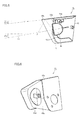
Fig. 5 is a partially enlarged cross-sectional view showing one example of the working lamp unit. -
Fig. 6 is an enlarged perspective view showing one example of a bracket for the working lamp unit shown inFig. 5 . -
Fig. 7 is a plan view of a bulldozer according to another embodiment of the present invention. -
Fig. 8 is a plan view of a motor grader according to still another embodiment of the present invention. - Embodiments of the present invention will be described hereinafter with reference to
Figs. 1 to 8 . An embodiment in which the idea of the present invention is applied to a wheel loader that is one example of a construction machine will be first described with reference toFigs. 1 to 6 . - An overall configuration of a
wheel loader 1 according to the present embodiment will now be described with reference toFigs. 1 and 2 . As shown inFigs. 1 and 2 ,wheel loader 1 includes arear vehicle body 2, afront frame 5 and anoperating device 30.Front wheels 3a are attached to the respective sides offront frame 5, andrear wheels 3b are attached to the respective sides ofrear vehicle body 2. -
Rear vehicle body 2 andfront frame 5 are connected by acenter pin 51 so as to freely swing to the right and left, and constitute an articulated structure.Rear vehicle body 2 andfront frame 5 are linked by one pair of right andleft steering cylinders 52. Theserear vehicle body 2 andfront frame 5 mainly constitute a vehicle body (construction machine main body) ofwheel loader 1. -
Operating device 30 is attached to a front part offront frame 5.Operating device 30 has aboom 31 having a base end swingably attached tofront frame 5, and abucket 32 swingably attached to a tip ofboom 31.Front frame 5 andboom 31 are linked by one pair ofboom cylinders 33. -
Operating device 30 also has atilt arm 34 swingably supported byboom 31 at a substantially central portion thereof, abucket cylinder 35 linking a base end oftilt arm 34 andfront frame 5, and atilt rod 36 linking a tip oftilt arm 34 andbucket 32. An engine room is arranged at a rear part ofrear vehicle body 2. In addition, anoperating room 6 is attached to an upper front part ofrear vehicle body 2. - As shown in
Figs. 1 and 2 , inwheel loader 1 according to the present embodiment, workinglamp units rear vehicle body 2. Acamera unit 4 is also placed on an upper surface ofrear vehicle body 2. - The working lamp unit is for illuminating an area around
wheel loader 1 including an operation area. In the present embodiment, workinglamp units wheel loader 1. Although two workinglamp units -
Camera unit 4 is located between workinglamp units rear vehicle body 2 and at a rear side end ofrear vehicle body 2. Using thiscamera unit 4, a picture of the rear area ofwheel loader 1 can be taken, and a state of the rear area ofwheel loader 1 can be checked through a monitor and the like. - As shown in
Fig. 3 , in the present embodiment, workinglamp unit 7b is arranged on asidewall 2a located near the upper surface ofrear vehicle body 2 and at a position displaced frontward from the rear side end ofrear vehicle body 2. As for the relationship withcamera unit 4, workinglamp unit 7b is arranged more frontward thancamera unit 4. - As shown in
Fig. 4 , workinglamp units camera unit 4, and thereby light can be emitted extensively from both sides ofcamera unit 4. In addition, workinglamp units rear vehicle body 2, and thereby a spacing between workinglamp units -
Light sources lamp units Fig. 4 ,light sources lamp units lamp units Fig. 4 , wide illuminatedareas - In addition, as shown in
Fig. 4 , workinglamp units rear vehicle body 2, and thereby the sidewalls ofrear vehicle body 2 can also be used as reflective surfaces. At this time, by configuring the sidewalls ofrear vehicle body 2 used as the reflective surfaces to have a high-lightness color such as yellow, orange and white, the sidewalls can efficiently reflect light from the light sources. - Next, a structural example of working
lamp unit 7b will be described with reference toFigs. 5 and 6 . As shown inFig. 5 , workinglamp unit 7b includeslight source 8b, and a mountingbracket 10 that houses thislight source 8b. - A halogen lamp can, for example, be used as
light source 8b.Light source 8b has a lens surface 8a1 directed to the light emission direction, and is fixed to mountingbracket 10 by a fixing member. - As shown in
Fig. 6 , mountingbracket 10 mainly includes aprotective cover portion 10a made of, for example, a metal and afront surface portion 10c made of a metal and having anopening 10d.Protective cover portion 10a has a function of protectinglight source 8b and is provided to surround an upper surface and a side surface oflight source 8b. In order to ensure the strength ofprotective cover portion 10a,protective cover portion 10a is preferably fabricated from a metallic plate member that has been subjected to bending work. -
Protective cover portion 10a also includes a pair of sidewall portions arranged on both sides oflight source 8b. At least one of the sidewall portions protrudes more in the light emission direction fromfront surface portion 10c. These sidewall portions can protectlight source 8b and inner surfaces of the sidewall portions can also be used as reflective surfaces. At this time, the inner surfaces of the sidewall portions used as the reflective surfaces may be mirror surfaces. When a coating is applied, it is preferable to apply a coating of a high-lightness color such as white and yellow. - In the example in
Fig. 6 , mountingbracket 10 is fixed torear vehicle body 2 by one sidewall portion ofprotective cover portion 10a. It is preferable to cause the sidewall portion that is not fixed to protrude more in the light emission direction than the sidewall portion that is fixed. Similarly, it is preferable to cause an upper surface portion ofprotective cover portion 10a located abovelight source 8b to protrude more in the light emission direction than the sidewall portion that is fixed torear vehicle body 2. As a result, a lower surface of this upper surface portion can be used as a reflective surface.Front surface portion 10c is made of a metallic plate-like member having a surface directed to the light emission direction, and receiveslight source 8b inopening 10d. - As shown in
Fig. 5 , a canopy portion (downward illuminating portion) 10b protruding more in the light illumination direction than lens surface 8a1 oflight source 8b is provided at a tip of the upper surface portion ofprotective cover portion 10a. Thiscanopy portion 10b can also be fabricated from a metallic plate member. It is preferable to apply a coating of a high-lightness color such as white and yellow to a lower surface of thiscanopy portion 10b. As a result, as shown inFig. 5 , the lower surface ofcanopy portion 10b can be used as a reflective surface. - As shown by a dotted arrow in
Fig. 5 , light emitted fromlight source 8b is reflected on the lower surface ofcanopy portion 10b and is directed downward. As a result, an area around a lower part ofwheel loader 1 can be illuminated with the light fromlight source 8b. On the other hand, direct light fromlight source 8b is emitted along an optical axis 11 toward a distant area and can illuminate the distant area as well. Consequently, visibility can be ensured both in the distant area and in the area nearwheel loader 1. - As shown in
Fig. 5 ,light source 8b is preferably arranged such that at least a part of lens surface 8a1 oflight source 8b protrudes in the light illumination direction fromfront surface portion 10c. As a result, light fromlight source 8b can be emitted extensively. In addition, by reflecting the extensively emitted light on the reflective surfaces, the light can be emitted more extensively. - In the example in
Fig. 5 , optical axis 11 oflight source 8b is inclined downward by an angle θ2 (e.g., approximately 5° to 15°) with respect to the horizontal direction. This also allows light fromlight source 8b to be directed downward. In addition, by causing at least a part of lens surface 8a1 oflight source 8b to protrude in the light illumination direction fromfront surface portion 10c and inclining optical axis 11 oflight source 8b downward, more light can be emitted downward. Furthermore, as shown inFig. 5 , by incliningcanopy portion 10b downward by an angle θ1 with respect to the horizontal direction, more light can be emitted downward. - In the example in
Fig. 5 , inclination angle θ2 of optical axis 11 oflight source 8b with respect to the horizontal direction is larger than inclination angle θ1 ofcanopy portion 10b with respect to the horizontal direction. As a result, more direct light fromlight source 8b can be emitted downward. On the other hand, it is also conceivable to set inclination angle θ2 of optical axis 11 oflight source 8b with respect to the horizontal direction to be smaller than inclination angle θ1 ofcanopy portion 10b with respect to the horizontal direction. In this case, an amount of light reflected fromcanopy portion 10b can be increased and more reflected light can be emitted downward. - As shown in
Fig. 5 , a portion offront surface portion 10c of mountingbracket 10 located below lens surface 8a1 oflight source 8b is preferably provided with an inclined portion 10c1 that is inclined with respect to the vertical direction toward the direction retracted with respect to the light illumination direction (toward the left side in the figure). As a result, as shown by the dotted arrow inFig. 5 , direct light fromlight source 8b can be directed downward and the area around the lower part ofwheel loader 1 can be illuminated with the direct light fromlight source 8b. - As shown in
Fig. 5 , a gap is provided betweenlight source 8b andfront surface portion 10c. As a result, interference betweenlight source 8b andfront surface portion 10c can be avoided. - Although the working lamp unit for illuminating the rear part of the wheel loader has been described by way of example in the aforementioned embodiment, the present invention is applicable to various construction machines other than the wheel loader. Specifically, the present invention is applicable to various construction machines such as, for example, a bulldozer, a scraper, a hydraulic excavator, a shovel loader, a mobile crane, and a motor grader. In addition, the aforementioned working lamp unit may be attached to the front side of the construction machine main body. In this case, similarly to the aforementioned embodiment, the working lamp unit may be arranged at a position displaced rearward from a front side end of the construction machine main body. A position where the working lamp unit is attached can, however, be selected arbitrarily.
-
Fig. 7 shows abulldozer 12 to which the present invention is applied. As shown inFig. 7 ,bulldozer 12 includes ablade 13, anengine hood 14 and acrawler belt 15. Workinglamp units engine hood 14 near a front end. The structure and the like of workinglamp units -
Fig. 8 shows amotor grader 16 to which the present invention is applied. As shown inFig. 7 ,motor grader 16 includes avehicle body 19 including arear frame 17 and afront frame 18.Rear wheels 20 are attached torear frame 17 andfront wheels 21 are attached tofront frame 18. Adrawbar 22 is mounted tofront frame 18 so as to freely swing up and down by an up-and-down cylinder 27. A blade functioning as an operating device is attached to a slewingcircle 23 ofdrawbar 22, and anarm 25 of ascarifier 24 is mounted tofront frame 18 so as to freely swing up and down by acylinder 26. Workinglamp units rear frame 17 near a rear end. The structure and the like of workinglamp units lamp units - Although the embodiments of the present invention have been described above, it should be understood that the embodiments disclosed herein are illustrative and not limitative in any respect. The scope of the present invention is defined by the terms of the claims, and is intended to include any modifications within the scope and meaning equivalent to the terms of the claims.
- 1 wheel loader; 2 rear vehicle body; 2a sidewall; 3a front wheel; 3b rear wheel; 4 camera unit; 5 front frame; 6 operating room; 7a, 7b working lamp unit; 8a, 8b light source; 8a1 lens surface; 9a, 9b illuminated area; 10 mounting bracket; 10a protective cover portion; 10b canopy portion; 10c front surface portion; 10c1 inclined portion; 10d opening; 11 optical axis; 12 bulldozer; 13 blade; 14 engine hood; 15 crawler belt; 16 motor grader; 17 rear frame; 18 front frame; 19 vehicle body; 20 rear wheel; 21 front wheel; 22 drawbar; 23 slewing circle; 24 scarifier; 25 arm; 26 cylinder; 27 up-and-down cylinder; 30 operating device; 31 boom; 32 bucket; 33 boom cylinder; 34 tilt arm; 35 bucket cylinder; 36 tilt rod; 51 center pin; 52 steering cylinder
Claims (7)
- A construction machine, comprising:a construction machine main body;an operating mechanism provided at said construction machine main body; anda working lamp unit attached to a sidewall of said construction machine main body,said working lamp unit having a light source and a bracket including a downward illuminating portion that covers at least an upper part of said light source and that protrudes more in light illumination direction than a lens surface of said light source and that is inclined downward with respect to a horizontal direction.
- The construction machine according to claim 1, wherein
said bracket has a front surface portion surrounding said light source, and
said light source is arranged such that at least a part of said lens surface of said light source protrudes in said light illumination direction from said front surface portion, and an optical axis of said light source is directed downward with respect to said horizontal direction. - The construction machine according to claim 2, wherein
an inclination angle of said optical axis of said light source with respect to said horizontal direction is set to be 5° to 15°. - The construction machine according to any one of claims 1 to 3, wherein
a portion of said front surface portion located below said lens surface of said light source is provided with an inclined portion that is inclined with respect to a vertical direction toward a direction retracted with respect to said light illumination direction. - The construction machine according to any one of claims 1 to 4, wherein
said working lamp unit is arranged at a position displaced rearward from a front side end of said construction machine main body or at a position displaced frontward from a rear side end of said construction machine main body. - The construction machine according to any one of claims 1 to 5, wherein
the inclination angle of said optical axis of said light source with respect to said horizontal direction is set to be larger than an inclination angle of said downward illuminating portion with respect to said horizontal direction. - The construction machine according to any one of claims 2 to 6, wherein
said bracket includes, around said front surface portion, at least one sidewall portion protruding more in said light illumination direction than said front surface portion.
Applications Claiming Priority (2)
| Application Number | Priority Date | Filing Date | Title |
|---|---|---|---|
| JP2011188834A JP5130391B1 (en) | 2011-08-31 | 2011-08-31 | Construction machinery |
| PCT/JP2012/068569 WO2013031427A1 (en) | 2011-08-31 | 2012-07-23 | Construction machine |
Publications (3)
| Publication Number | Publication Date |
|---|---|
| EP2752334A1 true EP2752334A1 (en) | 2014-07-09 |
| EP2752334A4 EP2752334A4 (en) | 2014-11-19 |
| EP2752334B1 EP2752334B1 (en) | 2016-11-09 |
Family
ID=47693001
Family Applications (1)
| Application Number | Title | Priority Date | Filing Date |
|---|---|---|---|
| EP12801789.4A Not-in-force EP2752334B1 (en) | 2011-08-31 | 2012-07-23 | Construction machine |
Country Status (5)
| Country | Link |
|---|---|
| US (1) | US8727588B2 (en) |
| EP (1) | EP2752334B1 (en) |
| JP (1) | JP5130391B1 (en) |
| CN (1) | CN103068632B (en) |
| WO (1) | WO2013031427A1 (en) |
Families Citing this family (6)
| Publication number | Priority date | Publication date | Assignee | Title |
|---|---|---|---|---|
| WO2015108505A1 (en) * | 2014-01-14 | 2015-07-23 | Volvo Construction Equipment Ab | Light arm locking mechanism for construction machines |
| WO2016136536A1 (en) * | 2015-02-23 | 2016-09-01 | 株式会社小松製作所 | Work vehicle |
| JP2016156262A (en) | 2015-02-23 | 2016-09-01 | 株式会社小松製作所 | Work vehicle |
| US10464619B2 (en) | 2016-02-05 | 2019-11-05 | Clark Equipment Company | Tracked utility vehicle |
| CN106661859A (en) | 2016-09-09 | 2017-05-10 | 株式会社小松制作所 | Bulldozer |
| WO2019073105A1 (en) | 2017-10-10 | 2019-04-18 | Herrmans Oy Ab | Working light |
Family Cites Families (14)
| Publication number | Priority date | Publication date | Assignee | Title |
|---|---|---|---|---|
| US4242045A (en) | 1979-06-01 | 1980-12-30 | General Electric Company | Trap seal for open circuit liquid cooled turbines |
| JPS569606U (en) * | 1979-07-03 | 1981-01-27 | ||
| JPS63207750A (en) * | 1987-02-24 | 1988-08-29 | Yanmar Diesel Engine Co Ltd | Rear-view mirror attaching structure for tractor |
| US5564749A (en) * | 1994-11-14 | 1996-10-15 | New Holland North America, Inc. | Reservoir tank for skid steer loaders |
| JP2000177479A (en) | 1998-12-21 | 2000-06-27 | Hitachi Constr Mach Co Ltd | Lighting system of construction machine |
| US6152586A (en) * | 1999-01-28 | 2000-11-28 | Transmatic, Inc. | Cargo area lighting system for trucks |
| JP2000296727A (en) | 1999-04-15 | 2000-10-24 | Furukawa Co Ltd | Wheel loader |
| US6254263B1 (en) * | 1999-11-04 | 2001-07-03 | Deere & Company | Protected lamp mounting assembly for an off road work vehicle |
| JP2004114850A (en) * | 2002-09-26 | 2004-04-15 | Shin Caterpillar Mitsubishi Ltd | Outside lighting system for work machine |
| JP3961927B2 (en) | 2002-10-25 | 2007-08-22 | 日立建機株式会社 | Construction equipment working equipment |
| US20050270778A1 (en) * | 2004-06-07 | 2005-12-08 | Deere & Company, A Delaware Corporation | Loader light mounting apparatus |
| JP2007231576A (en) | 2006-02-28 | 2007-09-13 | Komatsu Ltd | Construction machinery |
| JP2008095339A (en) | 2006-10-10 | 2008-04-24 | Shin Caterpillar Mitsubishi Ltd | Work machine |
| US20090196057A1 (en) * | 2008-01-31 | 2009-08-06 | Michael David Case | Side Lights For Work Vehicles |
-
2011
- 2011-08-31 JP JP2011188834A patent/JP5130391B1/en not_active Expired - Fee Related
-
2012
- 2012-07-23 EP EP12801789.4A patent/EP2752334B1/en not_active Not-in-force
- 2012-07-23 WO PCT/JP2012/068569 patent/WO2013031427A1/en not_active Ceased
- 2012-07-23 CN CN201280001845.1A patent/CN103068632B/en not_active Expired - Fee Related
- 2012-07-23 US US13/807,164 patent/US8727588B2/en active Active
Also Published As
| Publication number | Publication date |
|---|---|
| CN103068632A (en) | 2013-04-24 |
| JP5130391B1 (en) | 2013-01-30 |
| US20140078761A1 (en) | 2014-03-20 |
| EP2752334A4 (en) | 2014-11-19 |
| JP2013049987A (en) | 2013-03-14 |
| CN103068632B (en) | 2014-12-31 |
| WO2013031427A1 (en) | 2013-03-07 |
| US8727588B2 (en) | 2014-05-20 |
| EP2752334B1 (en) | 2016-11-09 |
Similar Documents
| Publication | Publication Date | Title |
|---|---|---|
| US8727588B2 (en) | Construction machine | |
| CN114945723B (en) | Working machine and working machine control method | |
| US8070334B2 (en) | Working machine | |
| CN212405311U (en) | Automatic traveling construction machine | |
| US20050270778A1 (en) | Loader light mounting apparatus | |
| US9624649B2 (en) | Wheel type working vehicle | |
| CN211774106U (en) | Automatic traveling construction machine | |
| JP2002339401A (en) | Lighting system of work machine | |
| JP7016774B2 (en) | Installation structure of electrical components and hydraulic hoses of work machines | |
| JP2006016914A (en) | Backward monitoring camera device | |
| CN106232904B (en) | work vehicle | |
| KR102758540B1 (en) | Self driving construction machine with an antenna fastening means | |
| EP2592188B1 (en) | Loader arm | |
| JP3179920U7 (en) | ||
| JP7157091B2 (en) | work vehicle | |
| JP2002180503A (en) | Work vehicle | |
| JP3179920U (en) | Work vehicle | |
| JP2001064998A (en) | Work light mounting structure for construction machinery | |
| JP7788992B2 (en) | Work equipment | |
| CN217923801U (en) | Excavator movable arm bucket rod with headlamp | |
| JP2003293395A (en) | Headlight device of construction machinery | |
| JP2003328393A (en) | Work equipment lighting equipment | |
| RU35329U1 (en) | Lifting crane | |
| JP2006249927A (en) | Ultra-small rotary work vehicle | |
| KR20060005338A (en) | Construction machinery |
Legal Events
| Date | Code | Title | Description |
|---|---|---|---|
| PUAI | Public reference made under article 153(3) epc to a published international application that has entered the european phase |
Free format text: ORIGINAL CODE: 0009012 |
|
| 17P | Request for examination filed |
Effective date: 20121227 |
|
| AK | Designated contracting states |
Kind code of ref document: A1 Designated state(s): AL AT BE BG CH CY CZ DE DK EE ES FI FR GB GR HR HU IE IS IT LI LT LU LV MC MK MT NL NO PL PT RO RS SE SI SK SM TR |
|
| A4 | Supplementary search report drawn up and despatched |
Effective date: 20141020 |
|
| RIC1 | Information provided on ipc code assigned before grant |
Ipc: B60Q 1/04 20060101ALI20141014BHEP Ipc: B60Q 1/24 20060101AFI20141014BHEP Ipc: E02F 9/08 20060101ALI20141014BHEP |
|
| DAX | Request for extension of the european patent (deleted) | ||
| 17Q | First examination report despatched |
Effective date: 20150911 |
|
| GRAP | Despatch of communication of intention to grant a patent |
Free format text: ORIGINAL CODE: EPIDOSNIGR1 |
|
| RIC1 | Information provided on ipc code assigned before grant |
Ipc: E02F 9/24 20060101ALI20160610BHEP Ipc: E02F 9/08 20060101ALI20160610BHEP Ipc: B60Q 1/04 20060101ALI20160610BHEP Ipc: B60Q 1/24 20060101AFI20160610BHEP Ipc: B60Q 1/22 20060101ALI20160610BHEP |
|
| INTG | Intention to grant announced |
Effective date: 20160706 |
|
| GRAS | Grant fee paid |
Free format text: ORIGINAL CODE: EPIDOSNIGR3 |
|
| GRAA | (expected) grant |
Free format text: ORIGINAL CODE: 0009210 |
|
| AK | Designated contracting states |
Kind code of ref document: B1 Designated state(s): AL AT BE BG CH CY CZ DE DK EE ES FI FR GB GR HR HU IE IS IT LI LT LU LV MC MK MT NL NO PL PT RO RS SE SI SK SM TR |
|
| REG | Reference to a national code |
Ref country code: GB Ref legal event code: FG4D |
|
| REG | Reference to a national code |
Ref country code: AT Ref legal event code: REF Ref document number: 843585 Country of ref document: AT Kind code of ref document: T Effective date: 20161115 Ref country code: CH Ref legal event code: EP |
|
| REG | Reference to a national code |
Ref country code: IE Ref legal event code: FG4D |
|
| REG | Reference to a national code |
Ref country code: DE Ref legal event code: R096 Ref document number: 602012025231 Country of ref document: DE |
|
| PG25 | Lapsed in a contracting state [announced via postgrant information from national office to epo] |
Ref country code: LV Free format text: LAPSE BECAUSE OF FAILURE TO SUBMIT A TRANSLATION OF THE DESCRIPTION OR TO PAY THE FEE WITHIN THE PRESCRIBED TIME-LIMIT Effective date: 20161109 |
|
| REG | Reference to a national code |
Ref country code: SE Ref legal event code: TRGR |
|
| REG | Reference to a national code |
Ref country code: LT Ref legal event code: MG4D |
|
| REG | Reference to a national code |
Ref country code: NL Ref legal event code: MP Effective date: 20161109 |
|
| REG | Reference to a national code |
Ref country code: AT Ref legal event code: MK05 Ref document number: 843585 Country of ref document: AT Kind code of ref document: T Effective date: 20161109 |
|
| PG25 | Lapsed in a contracting state [announced via postgrant information from national office to epo] |
Ref country code: LT Free format text: LAPSE BECAUSE OF FAILURE TO SUBMIT A TRANSLATION OF THE DESCRIPTION OR TO PAY THE FEE WITHIN THE PRESCRIBED TIME-LIMIT Effective date: 20161109 Ref country code: GR Free format text: LAPSE BECAUSE OF FAILURE TO SUBMIT A TRANSLATION OF THE DESCRIPTION OR TO PAY THE FEE WITHIN THE PRESCRIBED TIME-LIMIT Effective date: 20170210 Ref country code: NL Free format text: LAPSE BECAUSE OF FAILURE TO SUBMIT A TRANSLATION OF THE DESCRIPTION OR TO PAY THE FEE WITHIN THE PRESCRIBED TIME-LIMIT Effective date: 20161109 Ref country code: NO Free format text: LAPSE BECAUSE OF FAILURE TO SUBMIT A TRANSLATION OF THE DESCRIPTION OR TO PAY THE FEE WITHIN THE PRESCRIBED TIME-LIMIT Effective date: 20170209 |
|
| PG25 | Lapsed in a contracting state [announced via postgrant information from national office to epo] |
Ref country code: HR Free format text: LAPSE BECAUSE OF FAILURE TO SUBMIT A TRANSLATION OF THE DESCRIPTION OR TO PAY THE FEE WITHIN THE PRESCRIBED TIME-LIMIT Effective date: 20161109 Ref country code: AT Free format text: LAPSE BECAUSE OF FAILURE TO SUBMIT A TRANSLATION OF THE DESCRIPTION OR TO PAY THE FEE WITHIN THE PRESCRIBED TIME-LIMIT Effective date: 20161109 Ref country code: RS Free format text: LAPSE BECAUSE OF FAILURE TO SUBMIT A TRANSLATION OF THE DESCRIPTION OR TO PAY THE FEE WITHIN THE PRESCRIBED TIME-LIMIT Effective date: 20161109 Ref country code: PT Free format text: LAPSE BECAUSE OF FAILURE TO SUBMIT A TRANSLATION OF THE DESCRIPTION OR TO PAY THE FEE WITHIN THE PRESCRIBED TIME-LIMIT Effective date: 20170309 Ref country code: ES Free format text: LAPSE BECAUSE OF FAILURE TO SUBMIT A TRANSLATION OF THE DESCRIPTION OR TO PAY THE FEE WITHIN THE PRESCRIBED TIME-LIMIT Effective date: 20161109 Ref country code: FI Free format text: LAPSE BECAUSE OF FAILURE TO SUBMIT A TRANSLATION OF THE DESCRIPTION OR TO PAY THE FEE WITHIN THE PRESCRIBED TIME-LIMIT Effective date: 20161109 Ref country code: PL Free format text: LAPSE BECAUSE OF FAILURE TO SUBMIT A TRANSLATION OF THE DESCRIPTION OR TO PAY THE FEE WITHIN THE PRESCRIBED TIME-LIMIT Effective date: 20161109 Ref country code: IS Free format text: LAPSE BECAUSE OF FAILURE TO SUBMIT A TRANSLATION OF THE DESCRIPTION OR TO PAY THE FEE WITHIN THE PRESCRIBED TIME-LIMIT Effective date: 20170309 |
|
| PG25 | Lapsed in a contracting state [announced via postgrant information from national office to epo] |
Ref country code: RO Free format text: LAPSE BECAUSE OF FAILURE TO SUBMIT A TRANSLATION OF THE DESCRIPTION OR TO PAY THE FEE WITHIN THE PRESCRIBED TIME-LIMIT Effective date: 20161109 Ref country code: CZ Free format text: LAPSE BECAUSE OF FAILURE TO SUBMIT A TRANSLATION OF THE DESCRIPTION OR TO PAY THE FEE WITHIN THE PRESCRIBED TIME-LIMIT Effective date: 20161109 Ref country code: SK Free format text: LAPSE BECAUSE OF FAILURE TO SUBMIT A TRANSLATION OF THE DESCRIPTION OR TO PAY THE FEE WITHIN THE PRESCRIBED TIME-LIMIT Effective date: 20161109 Ref country code: EE Free format text: LAPSE BECAUSE OF FAILURE TO SUBMIT A TRANSLATION OF THE DESCRIPTION OR TO PAY THE FEE WITHIN THE PRESCRIBED TIME-LIMIT Effective date: 20161109 Ref country code: DK Free format text: LAPSE BECAUSE OF FAILURE TO SUBMIT A TRANSLATION OF THE DESCRIPTION OR TO PAY THE FEE WITHIN THE PRESCRIBED TIME-LIMIT Effective date: 20161109 |
|
| REG | Reference to a national code |
Ref country code: DE Ref legal event code: R097 Ref document number: 602012025231 Country of ref document: DE |
|
| PG25 | Lapsed in a contracting state [announced via postgrant information from national office to epo] |
Ref country code: IT Free format text: LAPSE BECAUSE OF FAILURE TO SUBMIT A TRANSLATION OF THE DESCRIPTION OR TO PAY THE FEE WITHIN THE PRESCRIBED TIME-LIMIT Effective date: 20161109 Ref country code: SM Free format text: LAPSE BECAUSE OF FAILURE TO SUBMIT A TRANSLATION OF THE DESCRIPTION OR TO PAY THE FEE WITHIN THE PRESCRIBED TIME-LIMIT Effective date: 20161109 Ref country code: BG Free format text: LAPSE BECAUSE OF FAILURE TO SUBMIT A TRANSLATION OF THE DESCRIPTION OR TO PAY THE FEE WITHIN THE PRESCRIBED TIME-LIMIT Effective date: 20170209 Ref country code: BE Free format text: LAPSE BECAUSE OF FAILURE TO SUBMIT A TRANSLATION OF THE DESCRIPTION OR TO PAY THE FEE WITHIN THE PRESCRIBED TIME-LIMIT Effective date: 20161109 |
|
| PLBE | No opposition filed within time limit |
Free format text: ORIGINAL CODE: 0009261 |
|
| STAA | Information on the status of an ep patent application or granted ep patent |
Free format text: STATUS: NO OPPOSITION FILED WITHIN TIME LIMIT |
|
| 26N | No opposition filed |
Effective date: 20170810 |
|
| PG25 | Lapsed in a contracting state [announced via postgrant information from national office to epo] |
Ref country code: SI Free format text: LAPSE BECAUSE OF FAILURE TO SUBMIT A TRANSLATION OF THE DESCRIPTION OR TO PAY THE FEE WITHIN THE PRESCRIBED TIME-LIMIT Effective date: 20161109 |
|
| REG | Reference to a national code |
Ref country code: CH Ref legal event code: PL |
|
| GBPC | Gb: european patent ceased through non-payment of renewal fee |
Effective date: 20170723 |
|
| REG | Reference to a national code |
Ref country code: IE Ref legal event code: MM4A |
|
| REG | Reference to a national code |
Ref country code: FR Ref legal event code: ST Effective date: 20180330 |
|
| PG25 | Lapsed in a contracting state [announced via postgrant information from national office to epo] |
Ref country code: GB Free format text: LAPSE BECAUSE OF NON-PAYMENT OF DUE FEES Effective date: 20170723 Ref country code: IE Free format text: LAPSE BECAUSE OF NON-PAYMENT OF DUE FEES Effective date: 20170723 Ref country code: LI Free format text: LAPSE BECAUSE OF NON-PAYMENT OF DUE FEES Effective date: 20170731 Ref country code: CH Free format text: LAPSE BECAUSE OF NON-PAYMENT OF DUE FEES Effective date: 20170731 |
|
| PG25 | Lapsed in a contracting state [announced via postgrant information from national office to epo] |
Ref country code: FR Free format text: LAPSE BECAUSE OF NON-PAYMENT OF DUE FEES Effective date: 20170731 |
|
| PG25 | Lapsed in a contracting state [announced via postgrant information from national office to epo] |
Ref country code: LU Free format text: LAPSE BECAUSE OF NON-PAYMENT OF DUE FEES Effective date: 20170723 |
|
| PG25 | Lapsed in a contracting state [announced via postgrant information from national office to epo] |
Ref country code: MT Free format text: LAPSE BECAUSE OF NON-PAYMENT OF DUE FEES Effective date: 20170723 |
|
| PG25 | Lapsed in a contracting state [announced via postgrant information from national office to epo] |
Ref country code: MC Free format text: LAPSE BECAUSE OF FAILURE TO SUBMIT A TRANSLATION OF THE DESCRIPTION OR TO PAY THE FEE WITHIN THE PRESCRIBED TIME-LIMIT Effective date: 20161109 Ref country code: HU Free format text: LAPSE BECAUSE OF FAILURE TO SUBMIT A TRANSLATION OF THE DESCRIPTION OR TO PAY THE FEE WITHIN THE PRESCRIBED TIME-LIMIT; INVALID AB INITIO Effective date: 20120723 |
|
| PG25 | Lapsed in a contracting state [announced via postgrant information from national office to epo] |
Ref country code: CY Free format text: LAPSE BECAUSE OF NON-PAYMENT OF DUE FEES Effective date: 20161109 |
|
| PG25 | Lapsed in a contracting state [announced via postgrant information from national office to epo] |
Ref country code: MK Free format text: LAPSE BECAUSE OF FAILURE TO SUBMIT A TRANSLATION OF THE DESCRIPTION OR TO PAY THE FEE WITHIN THE PRESCRIBED TIME-LIMIT Effective date: 20161109 |
|
| PG25 | Lapsed in a contracting state [announced via postgrant information from national office to epo] |
Ref country code: TR Free format text: LAPSE BECAUSE OF FAILURE TO SUBMIT A TRANSLATION OF THE DESCRIPTION OR TO PAY THE FEE WITHIN THE PRESCRIBED TIME-LIMIT Effective date: 20161109 |
|
| PG25 | Lapsed in a contracting state [announced via postgrant information from national office to epo] |
Ref country code: AL Free format text: LAPSE BECAUSE OF FAILURE TO SUBMIT A TRANSLATION OF THE DESCRIPTION OR TO PAY THE FEE WITHIN THE PRESCRIBED TIME-LIMIT Effective date: 20161109 |
|
| PGFP | Annual fee paid to national office [announced via postgrant information from national office to epo] |
Ref country code: SE Payment date: 20230613 Year of fee payment: 12 |
|
| PGFP | Annual fee paid to national office [announced via postgrant information from national office to epo] |
Ref country code: DE Payment date: 20230531 Year of fee payment: 12 |
|
| REG | Reference to a national code |
Ref country code: DE Ref legal event code: R119 Ref document number: 602012025231 Country of ref document: DE |
|
| REG | Reference to a national code |
Ref country code: SE Ref legal event code: EUG |
|
| PG25 | Lapsed in a contracting state [announced via postgrant information from national office to epo] |
Ref country code: DE Free format text: LAPSE BECAUSE OF NON-PAYMENT OF DUE FEES Effective date: 20250201 |
|
| PG25 | Lapsed in a contracting state [announced via postgrant information from national office to epo] |
Ref country code: SE Free format text: LAPSE BECAUSE OF NON-PAYMENT OF DUE FEES Effective date: 20240724 |