EP2752269A1 - Device and method for underwater welding - Google Patents
Device and method for underwater welding Download PDFInfo
- Publication number
- EP2752269A1 EP2752269A1 EP12826236.7A EP12826236A EP2752269A1 EP 2752269 A1 EP2752269 A1 EP 2752269A1 EP 12826236 A EP12826236 A EP 12826236A EP 2752269 A1 EP2752269 A1 EP 2752269A1
- Authority
- EP
- European Patent Office
- Prior art keywords
- underwater welding
- underwater
- shield cover
- expansion
- shield
- Prior art date
- Legal status (The legal status is an assumption and is not a legal conclusion. Google has not performed a legal analysis and makes no representation as to the accuracy of the status listed.)
- Granted
Links
Images



Classifications
-
- B—PERFORMING OPERATIONS; TRANSPORTING
- B23—MACHINE TOOLS; METAL-WORKING NOT OTHERWISE PROVIDED FOR
- B23K—SOLDERING OR UNSOLDERING; WELDING; CLADDING OR PLATING BY SOLDERING OR WELDING; CUTTING BY APPLYING HEAT LOCALLY, e.g. FLAME CUTTING; WORKING BY LASER BEAM
- B23K26/00—Working by laser beam, e.g. welding, cutting or boring
- B23K26/12—Working by laser beam, e.g. welding, cutting or boring in a special environment or atmosphere, e.g. in an enclosure
- B23K26/123—Working by laser beam, e.g. welding, cutting or boring in a special environment or atmosphere, e.g. in an enclosure in an atmosphere of particular gases
-
- B—PERFORMING OPERATIONS; TRANSPORTING
- B23—MACHINE TOOLS; METAL-WORKING NOT OTHERWISE PROVIDED FOR
- B23K—SOLDERING OR UNSOLDERING; WELDING; CLADDING OR PLATING BY SOLDERING OR WELDING; CUTTING BY APPLYING HEAT LOCALLY, e.g. FLAME CUTTING; WORKING BY LASER BEAM
- B23K26/00—Working by laser beam, e.g. welding, cutting or boring
- B23K26/12—Working by laser beam, e.g. welding, cutting or boring in a special environment or atmosphere, e.g. in an enclosure
- B23K26/1224—Working by laser beam, e.g. welding, cutting or boring in a special environment or atmosphere, e.g. in an enclosure in vacuum
Definitions
- Embodiments described herein relate generally to an underwater welding apparatus and method for performing underwater welding of, e.g., an in-reactor structure provided in reactor water of a nuclear reactor.
- an underwater welding apparatus that performs underwater welding
- an underwater welding apparatus that performs underwater repair for an in-reactor structure provided in reactor water of a nuclear reactor.
- Such an underwater welding apparatus needs to be configured to form underwater, at least around a welding pool, a space where water is excluded by means of gas during welding.
- various methods have been proposed to ensure a partial shield for forming the space where water is excluded around the welding pool.
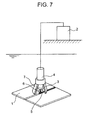
- a TIG welding power supply 2 is installed in the atmosphere, and only a welding torch 4 which is a welding head from which an arc 3 is generated is installed underwater.
- shield gas 6 is used to locally exclude water (welding part is shielded) so as to prevent the welding torch 4 and welding part 5 from contacting the water.
- the underwater machining apparatus described in Patent Document 1 uses, as a shield means for excluding the water, a combination of a highly elastic shield cover (solid wall) 7 made of a felt-like cloth woven from carbon fibers each having a thickness of about 5 mm and Ar gas.
- Patent Document 1 Japanese Patent No. 3,006,370
- the shield cover 7 used as the shield means described in Patent Document 1 may be turned up, resulting in introduction of the water into an inside (hereinafter, referred to as "chamber") of the shield cover 7.
- the water is collected inside the shield cover 7.
- the introduced water is mainly discharged from a pushing surface of the shield cover 7 by internal pressure of inert gas filled in the chamber 7.
- the water cannot be discharged completely, depending on attitude of the welding torch 4 serving as the welding head. For example, this may occur when the welding torch 4 is in an upward-facing attitude or laterally-facing attitude. This causes some of the water to be left behind in the chamber. To cope with such a case, it is necessary to provide a check valve or the like so as to discharge the residual water.
- fume metal dust particles each having a diameter of several ⁇ m to several tens of ⁇ m are generated. Particularly, in laser welding, a significant amount of fume is generated. When this fume is mixed with the water, it becomes a clayey substance having high viscosity, and this clayey substance may adhere to the valve seat of the check valve or an inside of a flow channel, impeding functions thereof.
- An object of the embodiments of the present invention is to provide an underwater welding apparatus and method capable of preventing the water outside the shield cover from being introduced and reliably and easily discharging the water and shield gas containing metal dust particles introduced inside the shield cover.
- an underwater welding apparatus comprising: an underwater welding head provided underwater and having, at its leading end, a nozzle section from which laser light is emitted; a shied cover formed of an elastic member and provided around the nozzle section so as to form, at the leading end of the underwater welding head, a space where water is excluded by means of shield gas; and an expansion/contraction member having a discharge hole for discharging water and shield gas containing metal dust particles from an inside of the shield cover, the discharge hole being increased in diameter as pressure inside the shield cover rises, while being reduced in diameter as the pressure inside the shield cover falls.
- an underwater welding method that provides an underwater welding head underwater and performs underwater welding of a part to be welded of a structure, the method comprising the steps of: forming, at a leading end side of the underwater welding head, a space where water is excluded by means of shield gas by using a shield cover formed of an elastic member and provided around a nozzle section from which laser light is emitted and which is provided at the leading end side of the underwater welding head; and discharging water and the shield gas containing metal dust particles inside the shield cover through a discharge hole of an expansion/contraction member, the discharge hole being increased in diameter as pressure inside the shield cover rises, while being reduced in diameter as the pressure inside the shield cover falls.
- FIG. 1 is an elevational cross-sectional view illustrating a first embodiment of an underwater welding apparatus according to the present invention.
- FIG. 2 is an enlarged cross-sectional view illustrating an expansion/contraction valve of FIG. 1 .
- FIG. 3 is an enlarged perspective view illustrating the expansion/contraction valve of FIG. 1 .
- a not illustrated laser oscillator is installed in the atmosphere, and only an underwater welding head 11 is installed underwater.
- Laser light emitted from the laser oscillator provided in the atmosphere is transmitted to the underwater welding head 11 through an optical fiber 12.
- inert gas serving as shield gas is supplied from a not illustrated shield gas supply source provided in the atmosphere to the underwater welding head 11 through an inert gas inlet 13.
- the underwater welding head 11 is formed into substantially a cylindrical shape. Inside the underwater welding head 11, there is provided an optical system 15 for collecting laser light 14. At a leading end side (left side of FIG. 1 ) of the underwater welding head 11, there is provided a large diameter portion 11a protruding in a flange-like manner toward an outer peripheral direction. At substantially center portion of the large diameter portion 11a, there is provided a nozzle section 16 for emitting the laser light 14 collected by the optical system 15 and ejecting the inert gas.
- the reflected light absorber 17 On a leading end side surface of the large diameter portion 11a, there is provided a reflected light absorber 17 for absorbing reflected light of the laser light 14 so as to surround the nozzle section 16.
- the reflected light absorber 17 is formed of a plate-like member formed into an annular shape and is firmly fixed to the large diameter portion 11a.
- a carbon plate can suitably be used as the plate-like member forming the reflected light absorber 17.
- a chamber 19 in which the inert gas is filled is formed inside the shield cover 18.
- a silicon rubber which is an elastic member having a comparatively small thickness is preferably used as the shield cover 18. The use of such a member can ensure waterproof properties and deformation performance.
- discharge routes 20a and 20b are formed up and down. Through the discharge routes 20a and 20b, the water introduced inside the chamber 19 is discharged. An expansion/contraction valve 21 as an expansion/contraction member is connected to the discharge route 20b formed at the lower portion of the large diameter portion 11a.
- the expansion/contraction valve 21 is formed into a spindle-shaped bag obtained by closing one side of a rubber tube, as illustrated in FIGS. 2 and 3 .
- the expansion/contraction valve 21 can expand and contract as a whole in accordance with pressure in the chamber 19. Specifically, the expansion/contraction valve 21 expands as the pressure inside the chamber 19 rises and contracts as the pressure inside the chamber 19 falls.
- the expansion/contraction valve 21 has, at its side surface, valve discharge holes 22 and 22, through which water 24 and gas containing fume 23 are discharged.
- valve discharge holes 22 and 22 are each increased and reduced in its diameter in accordance with the pressure inside the chamber 19. Specifically, the diameter of each of the valve discharge holes 22 and 22 is increased as the pressure inside the chamber 19 rises and reduced as the pressure inside the chamber 19 falls.
- the laser light 14 transmitted to the underwater welding head 11 through the optical fiber 12 is collected by the optical system 15 provided inside the underwater welding head 11 and emitted from the nozzle section 16 toward the material 10 to be welded.
- a not illustrated welding wire is supplied, and a welding pool 25 is formed in the material 10 to be welded, whereby welding work is executed.
- the reflected light absorber 17 for absorbing the reflected light is provided at a leading end side (left side of FIG. 1 ) portion of the underwater welding head 11 to be irradiated with the reflected light, so that a large proportion of the reflected light is absorbed by the reflected light absorber 17, which can significantly reduce a possibility that the reflected light is further reflected to reach the shield cover 18.
- the water 24 when the water 24 is introduced inside the chamber 19, the water 24 is collected inside the shield cover 18 in a mixed state with the fume 23 generated inside the chamber 19.
- the inert gas is filled in the chamber 19, so that the water 24 collected inside the chamber 19 is passed through the discharge route 20b formed in the large diameter portion 11a and then discharged through the valve discharge hole 22 formed in the expansion/contraction valve 21.
- the expansion/contraction valve 21 expands and contracts in accordance with the internal pressure in the chamber 19 to thereby prevent the fume 23 from being deposited in the valve discharge hole 22 and prevent introduction of the exterior water.
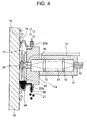
- FIG. 4 is an elevational cross-sectional view illustrating a second embodiment of the underwater welding apparatus according to the present invention.
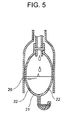
- FIG. 5 is an enlarged cross-sectional view illustrating the expansion/contraction valve and a protective tube which are illustrated in FIG. 4 .
- the same reference numerals are given to the same or corresponding parts of the first embodiment, and redundant explanations thereof will be omitted. The same is applied to a third embodiment to be described later.
- a protective tube 26 is provided around the expansion/contraction valve 21.
- the protective tube 26 is formed of a metal and disposed so as to surround the expansion/contraction valve 21 formed into a spindle-shape.
- a lower end of the protective tube 26 extends up to near the valve discharge hole 22 of the expansion/contraction valve 21.
- the protective tube 26 is provided around the expansion/contraction valve 21, which can prevent rupture of the expansion/contraction valve 21 even if the valve discharge hole 22 is clogged with deposition of the fume 23 to cause the expansion/contraction valve 21 to expand due to excessive rise in the internal pressure.
- FIG. 6 is an elevational cross-sectional view of a third embodiment of the underwater welding apparatus according to the present invention.
- a plurality of the expansion/contraction valves 21 are attached directly to the shield cover 18 by adhesive so as to be spaced at regular intervals along a circumferential direction of the shield cover 18.
- Each of the expansion/contraction valves 21 according to the present embodiment is formed of an elastic member having a thickness smaller than a thickness of the shield cover 18 and thus expands faster than the shield cover 18 when the internal pressure excessively rises.
- the expansion/contraction valve 21 is directly attached to the shield cover 18, thereby eliminating the need to form the discharge routes 20a and 20b in the large diameter portion 11a, which can simplify a structure of the underwater welding head 11.
- the expansion/contraction valve 21 is formed of rubber; however, any other material can be used as long as the expansion/contraction valve 21 can expand and contract in accordance with the internal pressure in the chamber 19 and the diameter of the valve discharge hole 22 can be increased and reduced in accordance with the expansion and contraction.
Landscapes
- Engineering & Computer Science (AREA)
- Physics & Mathematics (AREA)
- Plasma & Fusion (AREA)
- Mechanical Engineering (AREA)
- Optics & Photonics (AREA)
- Laser Beam Processing (AREA)
Abstract
Description
- Embodiments described herein relate generally to an underwater welding apparatus and method for performing underwater welding of, e.g., an in-reactor structure provided in reactor water of a nuclear reactor.
- There is conventionally known, as an underwater welding apparatus that performs underwater welding, an underwater welding apparatus that performs underwater repair for an in-reactor structure provided in reactor water of a nuclear reactor. Such an underwater welding apparatus needs to be configured to form underwater, at least around a welding pool, a space where water is excluded by means of gas during welding. Thus, various methods have been proposed to ensure a partial shield for forming the space where water is excluded around the welding pool.
- For example, in an underwater machining apparatus described in Patent Document 1, when a material 1 to be processed as a material to be welded provided in an underwater environment is welded as illustrated in
FIG. 7 , a TIG welding power supply 2 is installed in the atmosphere, and only awelding torch 4 which is a welding head from which anarc 3 is generated is installed underwater. In this state,shield gas 6 is used to locally exclude water (welding part is shielded) so as to prevent thewelding torch 4 and weldingpart 5 from contacting the water. - Moreover, the underwater machining apparatus described in Patent Document 1 uses, as a shield means for excluding the water, a combination of a highly elastic shield cover (solid wall) 7 made of a felt-like cloth woven from carbon fibers each having a thickness of about 5 mm and Ar gas.
- Patent Document 1: Japanese Patent No.
3,006,370 - However, in a case where continuous build-up welding of a groove is performed underwater on a cylindrical body such as a nozzle, the
shield cover 7 used as the shield means described in Patent Document 1 may be turned up, resulting in introduction of the water into an inside (hereinafter, referred to as "chamber") of theshield cover 7. - At installation time of the machining apparatus, the water is collected inside the
shield cover 7. When the water is introduced into the chamber of theshield cover 7, the introduced water is mainly discharged from a pushing surface of theshield cover 7 by internal pressure of inert gas filled in thechamber 7. - However, the water cannot be discharged completely, depending on attitude of the
welding torch 4 serving as the welding head. For example, this may occur when thewelding torch 4 is in an upward-facing attitude or laterally-facing attitude. This causes some of the water to be left behind in the chamber. To cope with such a case, it is necessary to provide a check valve or the like so as to discharge the residual water. - By the way, metal dust particles (hereinafter, sometimes referred to as "fume") each having a diameter of several µm to several tens of µm are generated. Particularly, in laser welding, a significant amount of fume is generated. When this fume is mixed with the water, it becomes a clayey substance having high viscosity, and this clayey substance may adhere to the valve seat of the check valve or an inside of a flow channel, impeding functions thereof.
- An object of the embodiments of the present invention is to provide an underwater welding apparatus and method capable of preventing the water outside the shield cover from being introduced and reliably and easily discharging the water and shield gas containing metal dust particles introduced inside the shield cover.
- In order to achieve the above-mentioned object, according to an embodiment, there is provided an underwater welding apparatus comprising: an underwater welding head provided underwater and having, at its leading end, a nozzle section from which laser light is emitted; a shied cover formed of an elastic member and provided around the nozzle section so as to form, at the leading end of the underwater welding head, a space where water is excluded by means of shield gas; and an expansion/contraction member having a discharge hole for discharging water and shield gas containing metal dust particles from an inside of the shield cover, the discharge hole being increased in diameter as pressure inside the shield cover rises, while being reduced in diameter as the pressure inside the shield cover falls.
- Furthermore in order to achieve the above-mentioned object, according to an embodiment, there is provided an underwater welding method that provides an underwater welding head underwater and performs underwater welding of a part to be welded of a structure, the method comprising the steps of: forming, at a leading end side of the underwater welding head, a space where water is excluded by means of shield gas by using a shield cover formed of an elastic member and provided around a nozzle section from which laser light is emitted and which is provided at the leading end side of the underwater welding head; and discharging water and the shield gas containing metal dust particles inside the shield cover through a discharge hole of an expansion/contraction member, the discharge hole being increased in diameter as pressure inside the shield cover rises, while being reduced in diameter as the pressure inside the shield cover falls.
- According to the embodiments of the present invention, it is possible to prevent the water outside the shield cover from being introduced and reliably and easily discharge the water and shield gas containing metal dust particles introduced inside the shield cover.
-
-
FIG. 1 is an elevational cross-sectional view illustrating a first embodiment of an underwater welding apparatus according to the present invention. -
FIG. 2 is an enlarged cross-sectional view illustrating an expansion/contraction valve ofFIG. 1 . -
FIG. 3 is an enlarged perspective view illustrating the expansion/contraction valve ofFIG. 1 . -
FIG. 4 is an elevational cross-sectional view illustrating a second embodiment of the underwater welding apparatus according to the present invention. -
FIG. 5 is an enlarged cross-sectional view illustrating the expansion/contraction valve and a protective tube which are illustrated inFIG. 4 . -
FIG. 6 is an elevational cross-sectional view of a third embodiment of the underwater welding apparatus according to the present invention. -
FIG. 7 is an entire configuration view of a conventional underwater welding apparatus. - Embodiments of an underwater welding machine according to the present invention will be described below with reference to the drawings.
-
FIG. 1 is an elevational cross-sectional view illustrating a first embodiment of an underwater welding apparatus according to the present invention.FIG. 2 is an enlarged cross-sectional view illustrating an expansion/contraction valve ofFIG. 1 .FIG. 3 is an enlarged perspective view illustrating the expansion/contraction valve ofFIG. 1 . - In the present embodiment, when a
material 10 to be welded provided in an underwater environment as illustrated inFIG. 1 is welded, a not illustrated laser oscillator is installed in the atmosphere, and only anunderwater welding head 11 is installed underwater. Laser light emitted from the laser oscillator provided in the atmosphere is transmitted to theunderwater welding head 11 through anoptical fiber 12. At the same time, inert gas serving as shield gas is supplied from a not illustrated shield gas supply source provided in the atmosphere to theunderwater welding head 11 through aninert gas inlet 13. - The
underwater welding head 11 is formed into substantially a cylindrical shape. Inside theunderwater welding head 11, there is provided anoptical system 15 for collectinglaser light 14. At a leading end side (left side ofFIG. 1 ) of theunderwater welding head 11, there is provided alarge diameter portion 11a protruding in a flange-like manner toward an outer peripheral direction. At substantially center portion of thelarge diameter portion 11a, there is provided anozzle section 16 for emitting thelaser light 14 collected by theoptical system 15 and ejecting the inert gas. - On a leading end side surface of the
large diameter portion 11a, there is provided a reflected light absorber 17 for absorbing reflected light of thelaser light 14 so as to surround thenozzle section 16. In the present embodiment, thereflected light absorber 17 is formed of a plate-like member formed into an annular shape and is firmly fixed to thelarge diameter portion 11a. For example, as the plate-like member forming the reflected light absorber 17, a carbon plate can suitably be used. - Around the reflected light absorber 17, a
shield cover 18 for forming, around a welding part, a space where the water is excluded by means of shield gas is provided so as to extend from a leading end outer peripheral surface of thelarge diameter portion 11a. Inside theshield cover 18, there is formed achamber 19 in which the inert gas is filled. As the shield cover 18, a silicon rubber which is an elastic member having a comparatively small thickness is preferably used. The use of such a member can ensure waterproof properties and deformation performance. - Inside the
large diameter portion 11a,discharge routes discharge routes chamber 19 is discharged. An expansion/contraction valve 21 as an expansion/contraction member is connected to thedischarge route 20b formed at the lower portion of thelarge diameter portion 11a. - The expansion/
contraction valve 21 is formed into a spindle-shaped bag obtained by closing one side of a rubber tube, as illustrated inFIGS. 2 and3 . The expansion/contraction valve 21 can expand and contract as a whole in accordance with pressure in thechamber 19. Specifically, the expansion/contraction valve 21 expands as the pressure inside thechamber 19 rises and contracts as the pressure inside thechamber 19 falls. The expansion/contraction valve 21 has, at its side surface,valve discharge holes water 24 andgas containing fume 23 are discharged. - Since the expansion/
contraction valve 21 can expand and contract as a whole, thevalve discharge holes chamber 19. Specifically, the diameter of each of the valve discharge holes 22 and 22 is increased as the pressure inside thechamber 19 rises and reduced as the pressure inside thechamber 19 falls. - The following describes operation of the present embodiment.
- In the underwater welding apparatus having the above configuration, the
laser light 14 transmitted to theunderwater welding head 11 through theoptical fiber 12 is collected by theoptical system 15 provided inside theunderwater welding head 11 and emitted from thenozzle section 16 toward the material 10 to be welded. At the same time, a not illustrated welding wire is supplied, and awelding pool 25 is formed in thematerial 10 to be welded, whereby welding work is executed. - During the welding work, a part of the
laser light 14 emitted from thenozzle section 16 to the material 10 to be welded is reflected at the material 10 to be welded and its neighboring portion to be reflected light. In the underwater welding apparatus according to the present embodiment, the reflectedlight absorber 17 for absorbing the reflected light is provided at a leading end side (left side ofFIG. 1 ) portion of theunderwater welding head 11 to be irradiated with the reflected light, so that a large proportion of the reflected light is absorbed by the reflectedlight absorber 17, which can significantly reduce a possibility that the reflected light is further reflected to reach theshield cover 18. - In the present embodiment, when the
water 24 is introduced inside thechamber 19, thewater 24 is collected inside theshield cover 18 in a mixed state with thefume 23 generated inside thechamber 19. - At this time, the inert gas is filled in the
chamber 19, so that thewater 24 collected inside thechamber 19 is passed through thedischarge route 20b formed in thelarge diameter portion 11a and then discharged through thevalve discharge hole 22 formed in the expansion/contraction valve 21. - When the
water 24 containing thefume 23 is discharged through thevalve discharge hole 22, thefume 23 is deposited in thevalve discharge hole 22 to clog thevalve discharge hole 22. When thevalve discharge hole 22 is clogged, the expansion/contraction valve 21 expands due to increase in the internal pressure in thechamber 19 to increase the diameter of thevalve discharge hole 22, with the result that thewater 24 is discharged. At this time, the internal pressure in thechamber 19 is increased, so that external water is not introduced even if the diameter of thevalve discharge hole 22 is increased. - As described above, according to the present embodiment, the expansion/
contraction valve 21 expands and contracts in accordance with the internal pressure in thechamber 19 to thereby prevent thefume 23 from being deposited in thevalve discharge hole 22 and prevent introduction of the exterior water. -
FIG. 4 is an elevational cross-sectional view illustrating a second embodiment of the underwater welding apparatus according to the present invention.FIG. 5 is an enlarged cross-sectional view illustrating the expansion/contraction valve and a protective tube which are illustrated inFIG. 4 . InFIGS. 4 and5 , the same reference numerals are given to the same or corresponding parts of the first embodiment, and redundant explanations thereof will be omitted. The same is applied to a third embodiment to be described later. - As illustrated in
FIGS. 4 and5 , in the present embodiment, aprotective tube 26 is provided around the expansion/contraction valve 21. Theprotective tube 26 is formed of a metal and disposed so as to surround the expansion/contraction valve 21 formed into a spindle-shape. A lower end of theprotective tube 26 extends up to near thevalve discharge hole 22 of the expansion/contraction valve 21. Thus, when the expansion/contraction valve 21 expands as the internal pressure in thechamber 19 rises, thevalve discharge hole 22 is exposed from theprotective tube 26. As a result, the diameter of thevalve discharge hole 22 can be increased in accordance with the internal pressure in thechamber 19. - As described above, according to the present embodiment, the
protective tube 26 is provided around the expansion/contraction valve 21, which can prevent rupture of the expansion/contraction valve 21 even if thevalve discharge hole 22 is clogged with deposition of thefume 23 to cause the expansion/contraction valve 21 to expand due to excessive rise in the internal pressure. -
FIG. 6 is an elevational cross-sectional view of a third embodiment of the underwater welding apparatus according to the present invention. - As illustrated in
FIG. 6 , in the present embodiment, a plurality of the expansion/contraction valves 21 are attached directly to theshield cover 18 by adhesive so as to be spaced at regular intervals along a circumferential direction of theshield cover 18. Each of the expansion/contraction valves 21 according to the present embodiment is formed of an elastic member having a thickness smaller than a thickness of theshield cover 18 and thus expands faster than theshield cover 18 when the internal pressure excessively rises. - As described above, according to the present embodiment, the expansion/
contraction valve 21 is directly attached to theshield cover 18, thereby eliminating the need to form thedischarge routes large diameter portion 11a, which can simplify a structure of theunderwater welding head 11. - Although the preferred embodiments of the present invention have been described above, the embodiments are merely illustrative and do not limit the scope of the present invention. These novel embodiments can be practiced in other various forms, and various omissions, substitutions and changes may be made without departing from the scope of the invention. The embodiments and modifications thereof are included in the scope or spirit of the present invention and in the appended claims and their equivalents.
- For example, in the above respective embodiments, the expansion/
contraction valve 21 is formed of rubber; however, any other material can be used as long as the expansion/contraction valve 21 can expand and contract in accordance with the internal pressure in thechamber 19 and the diameter of thevalve discharge hole 22 can be increased and reduced in accordance with the expansion and contraction. -
- 10: Material to be welded
- 11: Underwater welding head
- 11a: Large diameter portion
- 12: Optical fiber
- 13: Inert gas inlet
- 14: Laser light
- 15: Optical system
- 16: Nozzle section
- 17: Reflected light absorber
- 18: Shield cover
- 19: Chamber
- 20a, 20b: Discharge route
- 21: Expansion/contraction valve (expansion/contraction member)
- 22: Valve discharge hole
- 23: Fume
- 24: Water
- 25: Welding pool
- 26: Protective tube
Claims (4)
- An underwater welding apparatus comprising:an underwater welding head provided underwater and having, at its leading end, a nozzle section from which laser light is emitted;a shied cover formed of an elastic member and provided around the nozzle section so as to form, at the leading end of the underwater welding head, a space where water is excluded by means of shield gas; andan expansion/contraction member having a discharge hole for discharging water and shield gas containing metal dust particles from an inside of the shield cover, the discharge hole being increased in diameter as pressure inside the shield cover rises, while being reduced in diameter as the pressure inside the shield cover falls.
- The underwater welding apparatus according to claim 1, wherein
the expansion/contraction member is formed of an elastic rubber tube and is surrounded by a protective tube. - The underwater welding apparatus according to claim 1 or 2, wherein
the expansion/contraction member is attached to the shield cover. - An underwater welding method that provides an underwater welding head underwater and performs underwater welding of a part to be welded of a structure, the method comprising steps of:forming, at a leading end side of the underwater welding head, a space where water is excluded by means of shield gas by using a shield cover formed of an elastic member and provided around a nozzle section from which laser light is emitted and which is provided at the leading end side of the underwater welding head; anddischarging water and the shield gas containing metal dust particles inside the shield cover through a discharge hole of an expansion/contraction member, the discharge hole being increased in diameter as pressure inside the shield cover rises, while being reduced in diameter as the pressure inside the shield cover falls.
Applications Claiming Priority (2)
| Application Number | Priority Date | Filing Date | Title |
|---|---|---|---|
| JP2011182238A JP5767900B2 (en) | 2011-08-24 | 2011-08-24 | Underwater welding apparatus and method |
| PCT/JP2012/005261 WO2013027398A1 (en) | 2011-08-24 | 2012-08-22 | Device and method for underwater welding |
Publications (3)
| Publication Number | Publication Date |
|---|---|
| EP2752269A1 true EP2752269A1 (en) | 2014-07-09 |
| EP2752269A4 EP2752269A4 (en) | 2016-01-06 |
| EP2752269B1 EP2752269B1 (en) | 2018-08-01 |
Family
ID=47746158
Family Applications (1)
| Application Number | Title | Priority Date | Filing Date |
|---|---|---|---|
| EP12826236.7A Active EP2752269B1 (en) | 2011-08-24 | 2012-08-22 | Device and method for underwater welding |
Country Status (4)
| Country | Link |
|---|---|
| US (1) | US10052717B2 (en) |
| EP (1) | EP2752269B1 (en) |
| JP (1) | JP5767900B2 (en) |
| WO (1) | WO2013027398A1 (en) |
Cited By (1)
| Publication number | Priority date | Publication date | Assignee | Title |
|---|---|---|---|---|
| CN110280908A (en) * | 2019-07-24 | 2019-09-27 | 广州贤智科技有限公司 | A kind of environment-friendly type laser marking system with safeguard function |
Families Citing this family (10)
| Publication number | Priority date | Publication date | Assignee | Title |
|---|---|---|---|---|
| JP6109638B2 (en) * | 2013-05-14 | 2017-04-05 | 株式会社東芝 | Overlay welding apparatus and overlay welding system |
| CN103464901B (en) * | 2013-06-09 | 2015-12-23 | 湖南大学 | A kind of laser weld protective cover device |
| CN103551733A (en) * | 2013-10-25 | 2014-02-05 | 天津大学 | Method for decreasing welding fume of high-strength steel laser welding |
| CN103586565A (en) * | 2013-11-04 | 2014-02-19 | 哈尔滨工业大学(威海) | Underwater wet welding tracking system based on active vision |
| US20160303688A1 (en) * | 2015-04-20 | 2016-10-20 | Ford Motor Company | Gas Enclosure and Particle Shield for Laser Welding System |
| CN104923883B (en) * | 2015-07-02 | 2017-01-11 | 哈尔滨工业大学(威海) | Underground composite wet process welding device and method |
| CN104923882B (en) * | 2015-07-02 | 2017-01-11 | 哈尔滨工业大学(威海) | Underwater wet process welding device and method |
| CN105643097B (en) * | 2016-03-28 | 2017-11-03 | 东南大学 | A kind of underwater laser cutting drainage arrangement |
| WO2022249831A1 (en) * | 2021-05-28 | 2022-12-01 | コマツ産機株式会社 | Laser beam machining device, and nozzle unit for laser beam machining device |
| CN121447081B (en) * | 2026-01-06 | 2026-05-05 | 暨南大学 | Spray coating additive manufacturing equipment and arc spraying additive manufacturing method |
Family Cites Families (43)
| Publication number | Priority date | Publication date | Assignee | Title |
|---|---|---|---|---|
| US3118468A (en) * | 1961-04-20 | 1964-01-21 | Gen Electric | Resilient material check valve |
| FR2031728A5 (en) * | 1969-02-05 | 1970-11-20 | Sogetram Travaux Maritim | Underwater gas-screened fusible electrode - arc welding head |
| US3632950A (en) * | 1969-11-13 | 1972-01-04 | Anna Welding Corp | Method and apparatus for underwater arc welding |
| US3648015A (en) * | 1970-07-20 | 1972-03-07 | Thomas E Fairbairn | Radio frequency generated electron beam torch |
| FR2229241A5 (en) * | 1973-05-07 | 1974-12-06 | Oreal | |
| US3851864A (en) * | 1973-06-26 | 1974-12-03 | Lukens Steel Co | Apparatus and process for suppression of noise and fumes generated by plasma-arc cutting operation |
| ES208987Y (en) * | 1975-01-10 | 1976-08-16 | Baya Pena | DEVICE FOR CLEANING AND DISINFECTING THE NASAL FOSES. |
| US4114659A (en) * | 1975-06-18 | 1978-09-19 | Eitan Goldberg | Pipette filling and liquid dispensing device |
| US4102342A (en) * | 1975-12-29 | 1978-07-25 | Taichiro Akiyama | Valved device |
| GB1539917A (en) * | 1976-03-08 | 1979-02-07 | Boc Ltd | Methods of arc welding in a super-atmospheric environment |
| CH608568A5 (en) | 1976-03-05 | 1979-01-15 | Battelle Memorial Institute | |
| US4151393A (en) * | 1978-02-13 | 1979-04-24 | The United States Of America As Represented By The Secretary Of The Navy | Laser pile cutter |
| JPS5838274B2 (en) * | 1980-04-07 | 1983-08-22 | 科学技術庁金属材料技術研究所長 | Wet underwater welding equipment |
| US4475026A (en) * | 1982-07-26 | 1984-10-02 | Massachusetts Institute Of Technology | Underwater arc stud welding system |
| US4482246A (en) * | 1982-09-20 | 1984-11-13 | Meyer Gerhard A | Inductively coupled plasma discharge in flowing non-argon gas at atmospheric pressure for spectrochemical analysis |
| DK148075C (en) * | 1982-12-07 | 1985-07-29 | Gw Sprinkler As | A sprinkler |
| JPS5996313U (en) * | 1982-12-21 | 1984-06-29 | 株式会社小松製作所 | oil injection pipe device |
| GB8615437D0 (en) * | 1986-06-24 | 1986-07-30 | Bard Ltd | Pump |
| JPH01151862U (en) * | 1988-03-28 | 1989-10-19 | ||
| JP3006370B2 (en) * | 1993-11-10 | 2000-02-07 | 株式会社日立製作所 | Underwater processing equipment |
| JP3119090B2 (en) * | 1994-10-05 | 2000-12-18 | 株式会社日立製作所 | Underwater laser processing device and underwater construction method using the device |
| TW320586B (en) * | 1995-11-24 | 1997-11-21 | Hitachi Ltd | |
| US5811055A (en) * | 1996-02-06 | 1998-09-22 | Geiger; Michael B. | Torch mounted gas scavaging system for manual and robotic welding and cutting torches |
| US5717092A (en) | 1996-03-29 | 1998-02-10 | Vertex Pharmaceuticals Inc. | Compounds with improved multi-drug resistance activity |
| US5852271A (en) * | 1996-04-12 | 1998-12-22 | General Electric Company | Water exclusion device for underwater thermal processing |
| KR100255790B1 (en) * | 1998-04-09 | 2000-05-01 | 양원동 | Compressed water supply system and device for dental unit-chair |
| US6167925B1 (en) * | 1998-06-11 | 2001-01-02 | D'andrade Bruce M. | Bladder water gun with pump and quick charge system |
| US5961856A (en) * | 1998-07-10 | 1999-10-05 | General Electric Company | Deep water powder feed hopper |
| JP2000056070A (en) * | 1998-08-05 | 2000-02-25 | Toshiba Corp | Laser irradiation device |
| JP3806859B2 (en) * | 1999-09-24 | 2006-08-09 | 応研精工株式会社 | Diaphragm pump |
| JP2001219269A (en) * | 2000-02-07 | 2001-08-14 | Hitachi Ltd | Underwater processing device and its processing method |
| JP4155489B2 (en) * | 2000-09-28 | 2008-09-24 | 株式会社東芝 | Underwater laser repair welding equipment |
| GB0100877D0 (en) * | 2001-01-12 | 2001-02-21 | Mos Speciality Welds | Welding electrode holder |
| US6506995B1 (en) * | 2001-06-21 | 2003-01-14 | General Electric Company | Conforming welding torch shroud |
| US7164094B2 (en) * | 2004-01-12 | 2007-01-16 | General Electric Company | Apparatus and method for electrofriction welding |
| FR2908061B1 (en) * | 2006-11-07 | 2009-02-13 | Areva Np Sas | AUTOMATIC WELDING DEVICE AND METHOD FOR CARRYING ON A SURFACE OF A WELDING SEAL. |
| EP2207715B1 (en) * | 2007-10-29 | 2014-02-26 | Poseidon Diving Systems | Mouth piece for a breathing apparatus |
| US9050543B2 (en) * | 2007-11-14 | 2015-06-09 | Dan Barish | Bubble-producing devices and toy marksman kit including same |
| EP2323798A4 (en) * | 2008-08-07 | 2013-03-27 | Nelson Stud Welding Inc | Sealed and pressurized gun for underwater welding |
| US9080425B2 (en) * | 2008-10-17 | 2015-07-14 | Foro Energy, Inc. | High power laser photo-conversion assemblies, apparatuses and methods of use |
| JP2011016153A (en) * | 2009-07-09 | 2011-01-27 | Toshiba Corp | Underwater welding equipment |
| US8841127B2 (en) * | 2010-02-12 | 2014-09-23 | Northwestern University | Methods and devices for sample collection, treatment and dispensing |
| JP2012110945A (en) * | 2010-11-26 | 2012-06-14 | Toshiba Corp | Laser beam machining apparatus |
-
2011
- 2011-08-24 JP JP2011182238A patent/JP5767900B2/en active Active
-
2012
- 2012-08-22 US US14/131,119 patent/US10052717B2/en active Active
- 2012-08-22 WO PCT/JP2012/005261 patent/WO2013027398A1/en not_active Ceased
- 2012-08-22 EP EP12826236.7A patent/EP2752269B1/en active Active
Cited By (1)
| Publication number | Priority date | Publication date | Assignee | Title |
|---|---|---|---|---|
| CN110280908A (en) * | 2019-07-24 | 2019-09-27 | 广州贤智科技有限公司 | A kind of environment-friendly type laser marking system with safeguard function |
Also Published As
| Publication number | Publication date |
|---|---|
| US10052717B2 (en) | 2018-08-21 |
| EP2752269B1 (en) | 2018-08-01 |
| EP2752269A4 (en) | 2016-01-06 |
| JP5767900B2 (en) | 2015-08-26 |
| WO2013027398A1 (en) | 2013-02-28 |
| US20140231394A1 (en) | 2014-08-21 |
| JP2013043197A (en) | 2013-03-04 |
Similar Documents
| Publication | Publication Date | Title |
|---|---|---|
| EP2752269B1 (en) | Device and method for underwater welding | |
| JP4490608B2 (en) | Repair method of structure | |
| US8866040B2 (en) | Spatter removing device for laser welder | |
| JP5141034B2 (en) | Laser processing apparatus and laser processing method | |
| JP2011110556A (en) | Underwater welding apparatus and underwater welding method | |
| JP2015533425A (en) | Repair method for reactor-mounted instrumentation nozzle | |
| EP3124168B1 (en) | Water jet peening device | |
| JP2017154182A (en) | Protective shield for liquid induction laser cutting tools | |
| JP2011006789A (en) | Stress treatment device and operation system | |
| CN104023890A (en) | Wire EDM | |
| JP2007232457A (en) | Repairing method of penetration nozzle, and plug for nozzle port | |
| JP2014240090A (en) | Welding head and welding device | |
| CN107073393A (en) | The maintenance method of emission-control equipment and emission-control equipment | |
| KR101678506B1 (en) | Laser processing apparatus and laser processing method | |
| JP4494737B2 (en) | Method for sealing and repairing elongated hollow member of reactor pressure vessel, reactor pressure vessel and control rod drive housing | |
| JP4948755B2 (en) | Seal plate to repair damaged area of pressure vessel cladding | |
| JP2015009270A (en) | Laser processing head | |
| JP4363933B2 (en) | Underwater laser repair welding apparatus and underwater laser repair welding method | |
| JP6109698B2 (en) | Welding apparatus and welding method | |
| US20240131638A1 (en) | Overlay welding method and method for repairing metal member | |
| JP7719655B2 (en) | Submerged laser processing equipment | |
| JP2005326417A (en) | Method for repairing leaking elongated hollow member in boiling water reactor | |
| KR102819764B1 (en) | Nozzle Installation Structure of Laser Processing Machine | |
| JP2008139307A (en) | Reactor bottom head regeneration method realized | |
| JP5622407B2 (en) | Reactor pressure vessel residual stress improvement apparatus and reactor pressure vessel residual stress improvement method |
Legal Events
| Date | Code | Title | Description |
|---|---|---|---|
| PUAI | Public reference made under article 153(3) epc to a published international application that has entered the european phase |
Free format text: ORIGINAL CODE: 0009012 |
|
| 17P | Request for examination filed |
Effective date: 20140114 |
|
| AK | Designated contracting states |
Kind code of ref document: A1 Designated state(s): AL AT BE BG CH CY CZ DE DK EE ES FI FR GB GR HR HU IE IS IT LI LT LU LV MC MK MT NL NO PL PT RO RS SE SI SK SM TR |
|
| DAX | Request for extension of the european patent (deleted) | ||
| RA4 | Supplementary search report drawn up and despatched (corrected) |
Effective date: 20151204 |
|
| RIC1 | Information provided on ipc code assigned before grant |
Ipc: B23K 26/20 20140101ALI20151130BHEP Ipc: B23K 26/12 20060101AFI20151130BHEP Ipc: B23K 26/16 20060101ALI20151130BHEP |
|
| GRAP | Despatch of communication of intention to grant a patent |
Free format text: ORIGINAL CODE: EPIDOSNIGR1 |
|
| STAA | Information on the status of an ep patent application or granted ep patent |
Free format text: STATUS: GRANT OF PATENT IS INTENDED |
|
| INTG | Intention to grant announced |
Effective date: 20180404 |
|
| GRAS | Grant fee paid |
Free format text: ORIGINAL CODE: EPIDOSNIGR3 |
|
| GRAA | (expected) grant |
Free format text: ORIGINAL CODE: 0009210 |
|
| STAA | Information on the status of an ep patent application or granted ep patent |
Free format text: STATUS: THE PATENT HAS BEEN GRANTED |
|
| AK | Designated contracting states |
Kind code of ref document: B1 Designated state(s): AL AT BE BG CH CY CZ DE DK EE ES FI FR GB GR HR HU IE IS IT LI LT LU LV MC MK MT NL NO PL PT RO RS SE SI SK SM TR |
|
| REG | Reference to a national code |
Ref country code: GB Ref legal event code: FG4D |
|
| REG | Reference to a national code |
Ref country code: FR Ref legal event code: PLFP Year of fee payment: 7 |
|
| REG | Reference to a national code |
Ref country code: CH Ref legal event code: EP Ref country code: AT Ref legal event code: REF Ref document number: 1023729 Country of ref document: AT Kind code of ref document: T Effective date: 20180815 |
|
| REG | Reference to a national code |
Ref country code: IE Ref legal event code: FG4D |
|
| REG | Reference to a national code |
Ref country code: DE Ref legal event code: R096 Ref document number: 602012049241 Country of ref document: DE |
|
| REG | Reference to a national code |
Ref country code: SE Ref legal event code: TRGR |
|
| REG | Reference to a national code |
Ref country code: NL Ref legal event code: MP Effective date: 20180801 |
|
| REG | Reference to a national code |
Ref country code: LT Ref legal event code: MG4D |
|
| REG | Reference to a national code |
Ref country code: AT Ref legal event code: MK05 Ref document number: 1023729 Country of ref document: AT Kind code of ref document: T Effective date: 20180801 |
|
| PG25 | Lapsed in a contracting state [announced via postgrant information from national office to epo] |
Ref country code: FI Free format text: LAPSE BECAUSE OF FAILURE TO SUBMIT A TRANSLATION OF THE DESCRIPTION OR TO PAY THE FEE WITHIN THE PRESCRIBED TIME-LIMIT Effective date: 20180801 Ref country code: LT Free format text: LAPSE BECAUSE OF FAILURE TO SUBMIT A TRANSLATION OF THE DESCRIPTION OR TO PAY THE FEE WITHIN THE PRESCRIBED TIME-LIMIT Effective date: 20180801 Ref country code: PL Free format text: LAPSE BECAUSE OF FAILURE TO SUBMIT A TRANSLATION OF THE DESCRIPTION OR TO PAY THE FEE WITHIN THE PRESCRIBED TIME-LIMIT Effective date: 20180801 Ref country code: IS Free format text: LAPSE BECAUSE OF FAILURE TO SUBMIT A TRANSLATION OF THE DESCRIPTION OR TO PAY THE FEE WITHIN THE PRESCRIBED TIME-LIMIT Effective date: 20181201 Ref country code: RS Free format text: LAPSE BECAUSE OF FAILURE TO SUBMIT A TRANSLATION OF THE DESCRIPTION OR TO PAY THE FEE WITHIN THE PRESCRIBED TIME-LIMIT Effective date: 20180801 Ref country code: NO Free format text: LAPSE BECAUSE OF FAILURE TO SUBMIT A TRANSLATION OF THE DESCRIPTION OR TO PAY THE FEE WITHIN THE PRESCRIBED TIME-LIMIT Effective date: 20181101 Ref country code: GR Free format text: LAPSE BECAUSE OF FAILURE TO SUBMIT A TRANSLATION OF THE DESCRIPTION OR TO PAY THE FEE WITHIN THE PRESCRIBED TIME-LIMIT Effective date: 20181102 Ref country code: NL Free format text: LAPSE BECAUSE OF FAILURE TO SUBMIT A TRANSLATION OF THE DESCRIPTION OR TO PAY THE FEE WITHIN THE PRESCRIBED TIME-LIMIT Effective date: 20180801 Ref country code: AT Free format text: LAPSE BECAUSE OF FAILURE TO SUBMIT A TRANSLATION OF THE DESCRIPTION OR TO PAY THE FEE WITHIN THE PRESCRIBED TIME-LIMIT Effective date: 20180801 Ref country code: BG Free format text: LAPSE BECAUSE OF FAILURE TO SUBMIT A TRANSLATION OF THE DESCRIPTION OR TO PAY THE FEE WITHIN THE PRESCRIBED TIME-LIMIT Effective date: 20181101 |
|
| PG25 | Lapsed in a contracting state [announced via postgrant information from national office to epo] |
Ref country code: LV Free format text: LAPSE BECAUSE OF FAILURE TO SUBMIT A TRANSLATION OF THE DESCRIPTION OR TO PAY THE FEE WITHIN THE PRESCRIBED TIME-LIMIT Effective date: 20180801 Ref country code: HR Free format text: LAPSE BECAUSE OF FAILURE TO SUBMIT A TRANSLATION OF THE DESCRIPTION OR TO PAY THE FEE WITHIN THE PRESCRIBED TIME-LIMIT Effective date: 20180801 Ref country code: AL Free format text: LAPSE BECAUSE OF FAILURE TO SUBMIT A TRANSLATION OF THE DESCRIPTION OR TO PAY THE FEE WITHIN THE PRESCRIBED TIME-LIMIT Effective date: 20180801 |
|
| REG | Reference to a national code |
Ref country code: DE Ref legal event code: R119 Ref document number: 602012049241 Country of ref document: DE |
|
| REG | Reference to a national code |
Ref country code: CH Ref legal event code: PL |
|
| PG25 | Lapsed in a contracting state [announced via postgrant information from national office to epo] |
Ref country code: IT Free format text: LAPSE BECAUSE OF FAILURE TO SUBMIT A TRANSLATION OF THE DESCRIPTION OR TO PAY THE FEE WITHIN THE PRESCRIBED TIME-LIMIT Effective date: 20180801 Ref country code: LI Free format text: LAPSE BECAUSE OF NON-PAYMENT OF DUE FEES Effective date: 20180831 Ref country code: ES Free format text: LAPSE BECAUSE OF FAILURE TO SUBMIT A TRANSLATION OF THE DESCRIPTION OR TO PAY THE FEE WITHIN THE PRESCRIBED TIME-LIMIT Effective date: 20180801 Ref country code: RO Free format text: LAPSE BECAUSE OF FAILURE TO SUBMIT A TRANSLATION OF THE DESCRIPTION OR TO PAY THE FEE WITHIN THE PRESCRIBED TIME-LIMIT Effective date: 20180801 Ref country code: CZ Free format text: LAPSE BECAUSE OF FAILURE TO SUBMIT A TRANSLATION OF THE DESCRIPTION OR TO PAY THE FEE WITHIN THE PRESCRIBED TIME-LIMIT Effective date: 20180801 Ref country code: CH Free format text: LAPSE BECAUSE OF NON-PAYMENT OF DUE FEES Effective date: 20180831 Ref country code: EE Free format text: LAPSE BECAUSE OF FAILURE TO SUBMIT A TRANSLATION OF THE DESCRIPTION OR TO PAY THE FEE WITHIN THE PRESCRIBED TIME-LIMIT Effective date: 20180801 Ref country code: LU Free format text: LAPSE BECAUSE OF NON-PAYMENT OF DUE FEES Effective date: 20180822 Ref country code: MC Free format text: LAPSE BECAUSE OF FAILURE TO SUBMIT A TRANSLATION OF THE DESCRIPTION OR TO PAY THE FEE WITHIN THE PRESCRIBED TIME-LIMIT Effective date: 20180801 |
|
| REG | Reference to a national code |
Ref country code: BE Ref legal event code: MM Effective date: 20180831 |
|
| PG25 | Lapsed in a contracting state [announced via postgrant information from national office to epo] |
Ref country code: DK Free format text: LAPSE BECAUSE OF FAILURE TO SUBMIT A TRANSLATION OF THE DESCRIPTION OR TO PAY THE FEE WITHIN THE PRESCRIBED TIME-LIMIT Effective date: 20180801 Ref country code: SK Free format text: LAPSE BECAUSE OF FAILURE TO SUBMIT A TRANSLATION OF THE DESCRIPTION OR TO PAY THE FEE WITHIN THE PRESCRIBED TIME-LIMIT Effective date: 20180801 Ref country code: SM Free format text: LAPSE BECAUSE OF FAILURE TO SUBMIT A TRANSLATION OF THE DESCRIPTION OR TO PAY THE FEE WITHIN THE PRESCRIBED TIME-LIMIT Effective date: 20180801 |
|
| PLBE | No opposition filed within time limit |
Free format text: ORIGINAL CODE: 0009261 |
|
| STAA | Information on the status of an ep patent application or granted ep patent |
Free format text: STATUS: NO OPPOSITION FILED WITHIN TIME LIMIT |
|
| 26N | No opposition filed |
Effective date: 20190503 |
|
| GBPC | Gb: european patent ceased through non-payment of renewal fee |
Effective date: 20181101 |
|
| PG25 | Lapsed in a contracting state [announced via postgrant information from national office to epo] |
Ref country code: DE Free format text: LAPSE BECAUSE OF NON-PAYMENT OF DUE FEES Effective date: 20190301 |
|
| PG25 | Lapsed in a contracting state [announced via postgrant information from national office to epo] |
Ref country code: SI Free format text: LAPSE BECAUSE OF FAILURE TO SUBMIT A TRANSLATION OF THE DESCRIPTION OR TO PAY THE FEE WITHIN THE PRESCRIBED TIME-LIMIT Effective date: 20180801 Ref country code: BE Free format text: LAPSE BECAUSE OF NON-PAYMENT OF DUE FEES Effective date: 20180831 |
|
| PG25 | Lapsed in a contracting state [announced via postgrant information from national office to epo] |
Ref country code: GB Free format text: LAPSE BECAUSE OF NON-PAYMENT OF DUE FEES Effective date: 20181101 |
|
| PG25 | Lapsed in a contracting state [announced via postgrant information from national office to epo] |
Ref country code: MT Free format text: LAPSE BECAUSE OF NON-PAYMENT OF DUE FEES Effective date: 20180822 |
|
| PG25 | Lapsed in a contracting state [announced via postgrant information from national office to epo] |
Ref country code: TR Free format text: LAPSE BECAUSE OF FAILURE TO SUBMIT A TRANSLATION OF THE DESCRIPTION OR TO PAY THE FEE WITHIN THE PRESCRIBED TIME-LIMIT Effective date: 20180801 |
|
| PG25 | Lapsed in a contracting state [announced via postgrant information from national office to epo] |
Ref country code: PT Free format text: LAPSE BECAUSE OF FAILURE TO SUBMIT A TRANSLATION OF THE DESCRIPTION OR TO PAY THE FEE WITHIN THE PRESCRIBED TIME-LIMIT Effective date: 20180801 Ref country code: HU Free format text: LAPSE BECAUSE OF FAILURE TO SUBMIT A TRANSLATION OF THE DESCRIPTION OR TO PAY THE FEE WITHIN THE PRESCRIBED TIME-LIMIT; INVALID AB INITIO Effective date: 20120822 |
|
| PG25 | Lapsed in a contracting state [announced via postgrant information from national office to epo] |
Ref country code: IE Free format text: LAPSE BECAUSE OF NON-PAYMENT OF DUE FEES Effective date: 20180822 Ref country code: MK Free format text: LAPSE BECAUSE OF NON-PAYMENT OF DUE FEES Effective date: 20180801 Ref country code: CY Free format text: LAPSE BECAUSE OF FAILURE TO SUBMIT A TRANSLATION OF THE DESCRIPTION OR TO PAY THE FEE WITHIN THE PRESCRIBED TIME-LIMIT Effective date: 20180801 |
|
| PGFP | Annual fee paid to national office [announced via postgrant information from national office to epo] |
Ref country code: SE Payment date: 20230613 Year of fee payment: 12 |
|
| REG | Reference to a national code |
Ref country code: SE Ref legal event code: EUG |
|
| PG25 | Lapsed in a contracting state [announced via postgrant information from national office to epo] |
Ref country code: SE Free format text: LAPSE BECAUSE OF NON-PAYMENT OF DUE FEES Effective date: 20240823 |
|
| PGFP | Annual fee paid to national office [announced via postgrant information from national office to epo] |
Ref country code: FR Payment date: 20250703 Year of fee payment: 14 |