EP2751824B1 - A quenching chamber for a circuit interrupter - Google Patents
A quenching chamber for a circuit interrupter Download PDFInfo
- Publication number
- EP2751824B1 EP2751824B1 EP11748691.0A EP11748691A EP2751824B1 EP 2751824 B1 EP2751824 B1 EP 2751824B1 EP 11748691 A EP11748691 A EP 11748691A EP 2751824 B1 EP2751824 B1 EP 2751824B1
- Authority
- EP
- European Patent Office
- Prior art keywords
- quenching
- wall
- chamber
- capabilities
- space
- Prior art date
- Legal status (The legal status is an assumption and is not a legal conclusion. Google has not performed a legal analysis and makes no representation as to the accuracy of the status listed.)
- Active
Links
Images


Classifications
-
- H—ELECTRICITY
- H01—ELECTRIC ELEMENTS
- H01H—ELECTRIC SWITCHES; RELAYS; SELECTORS; EMERGENCY PROTECTIVE DEVICES
- H01H9/00—Details of switching devices, not covered by groups H01H1/00 - H01H7/00
- H01H9/30—Means for extinguishing or preventing arc between current-carrying parts
- H01H9/302—Means for extinguishing or preventing arc between current-carrying parts wherein arc-extinguishing gas is evolved from stationary parts
-
- H—ELECTRICITY
- H01—ELECTRIC ELEMENTS
- H01H—ELECTRIC SWITCHES; RELAYS; SELECTORS; EMERGENCY PROTECTIVE DEVICES
- H01H9/00—Details of switching devices, not covered by groups H01H1/00 - H01H7/00
- H01H9/30—Means for extinguishing or preventing arc between current-carrying parts
- H01H9/34—Stationary parts for restricting or subdividing the arc, e.g. barrier plate
- H01H9/346—Details concerning the arc formation chamber
Definitions
- the present invention refers to a quenching chamber for a circuit interrupter according to the pre-characterised portion of claim 1 and a method for quenching an electrical arc according to the pre-characterised portion of claim 14.
- a circuit breaker is an example of a device used to interrupt a current upon occurrence of over-heating or overcurrent.
- the switch or breaker comprises a movable contact, which can be separated from a fixed contact to interrupt the current path.
- An electrical arc between the contacts may be formed during switching or breaking or a disconnecting operation.
- An arc voltage is developed across the contacts as the contacts move away from one another during the interruption event.
- Metal particles may be scattered from the contacts and gases may be released from the material surrounding the contacts during the formation of the arc.
- a pressure may build up inside the switch or breaker by the released gases.
- the arc event further increases the heat in the switch or breaker. These subsequent events such as pressure building and raises in temperature may result in re-ignition of the arc. Repeated interruption of the current in a switch or breaker is detrimental for the lifetime of the circuit interrupter and may decrement the operational reliability of the interrupter.
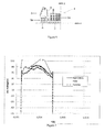
- Fig 1 shows a schematic plot of an arc event, wherein the current or arc voltage on the y-axis is plotted versus time on the x-axis.
- the peak let through current (area B, time zone 2 in Fig 1 ) may be lowered, by providing dissipating structures such as arc chutes in the switch or breaker to assist in dissipation.
- US 5,589,672 describes a circuit breaker with an arc quenching device and a vent.
- arc quenching material disposed in the proximity of the contacts. This material may be aligned to the wall of a quenching chamber that surrounds the contacts. Quenching material ablates by the arc during an arc event. The ablation vapors interact with the arc to absorb the arcing energy, thereby cooling the arc temperature and dissipating the arc. Arc quenching materials may be used for lowering the peak let through energy and decreasing re-ignition probability. The material may be used for extending the life of the switch or breaker and improving operational reliability of the interrupter.
- quenching materials have been used, whereby the different materials influence the arc in different ways.
- some materials may be capable to ablate rapidly at the start of the arc event (area A, time zone 1 in Fig 1 ).
- Other materials may be capable of cooling the environment around the contacts and have more influence on lowering the peak let through current (area B, time zone 2 in Fig 1 ).
- Yet further materials may be capable to neutralise the particles present around the contacts after the arc event and have more influence on heat dissipation and neutralisation (area C, time zone 3 in Fig 1 ).
- Quenching materials may influence one specific area of the curve shown in Fig 1 . However, quenching materials may at the same time also influence other areas of the curve.
- Quenching material is mostly used to lower the peak let through energy.
- US 2008/0073326 describes a quenching chamber that includes a vent and quenching material aligned on part of the wall of the chamber to reduce the peak let through current.
- US 5,841,088 describes a quenching chamber, whereby the walls of the chamber are aligned with two different quenching materials such that the area around the contacts in the chamber is symmetrically surrounded by a first quenching material, and whereby the first material is covered by a second quenching material on the surface that faces away from the contacts.
- the first quenching material is used to improve the quenching or extinguishing properties
- the second material is used to improve the strength against pressure building in the chamber.
- US2008/0061037 also describes a quenching chamber for a circuit interrupter comprising a space, and a wall surrounding the space.
- a switch In the space a switch is present having a fixed contact and a movable contact between which contacts an arc can be generated.
- the wall of the quenching chamber comprises two or more levels of wall units, whereby the wall unit within one level symmetrically surround the space by extending over the width of the wall along a first axis and extending along a part of the length of the wall along a second axis being perpendicular to the first axis.
- Each wall unit comprises quenching material, whereby the quenching materials are different in two adjacent levels.
- One of the quenching materials used provides a relatively high ablation, generating large volumes of ablation vapors to lower the arc temperature and help quenching the arc.
- the other quenching material used provides a relative low ablation to limit the pressure increase and allowing arc quenching to proceed with less interference from an ablation vapor-induced pressure rise.
- a quenching chamber which can be adapted to specific conditions in which the chamber will be used.
- a quenching chamber comprising quenching material that can be easily varied and adapted to the specific operational needs of the interrupter.
- an improved quenching chamber wherein the electrical arc can be extinguished quicker and whereby the lifetime of the interrupter can be extended.
- improved quenching material there is a need for improved quenching material.
- the object of the invention is to provide a quenching chamber comprising arc quenching material that lowers the peak let through energy, and/or lowers the pressure build and/or decreases re-ignition probability. It is another object to extend the lifetime of the interrupter. It is a further object to improve the heat resistance in the quenching chamber. It is also an object to improve the operational reliability of the interrupter. It is furthermore an object to provide a quenching chamber, which can easily be adapted to different operational requirement.
- the inventors have surprisingly found that the asymmetric alignment of at least two quenching materials that have different quenching capabilities, on opposite walls improves the performances of the quenching chamber.
- the rapid ablative material ablates, the vapor gases from this material will push the arc sidewards.
- the sidewards bending of the arc inside the quenching chamber as illustrated by the arrow in Fig 2 increases the length of the arc such that more energy is needed to maintain the arc. Thereby, the peak let through energy decreases.
- the second (and subsequent) quenching material may ablate with reduced quantities of vapor gases such that the pressure build up in the chamber decreases compared to using only the rapid ablative material.
- Heat resistance is likewise improved because not only rapid ablative material is being used but even quenching material, which has excellent cooling and/or neutralisation qualities. As a consequence, the risk for re-ignition of the arc is substantially reduced. Because the extinction of the arc occurs faster, less damage will be caused by the arc, which in turn improved the lifetime of the circuit interrupter. Reduced damage also improves the reliability of the circuit interrupter.
- the quenching materials that have different quenching capabilities can be easily substituted by other material and thus allow for combining different quenching materials in many different ways.
- the new chamber can thus be easily adapted for different operational requirements such as higher voltages, smaller circuits, etc. In small circuits for example, rapid ablation and cooling may be more important than neutralisation.
- the quenching chamber may comprise asymmetric levels comprising materials that rapidly ablate at the start or onset of the arc event and material which has good cooling capabilities (area A and B in Fig 1 ).
- the quenching material is selected from a first material having ablation capability at a start of a circuit interruption, a second material having cooling capabilities and a third material having neutralisation capabilities, or any mixtures thereof.
- the first material ablates faster than the second and third material, and the second material cools the space faster than the first and third material, and the third material neutralises faster than the first and second material.
- the quenching materials used may have effects in more than one region, but a particular material will perform better in one particular region, while another material performs better in a another region.
- the quenching chamber is configured to be adapted to the diversity of operational conditions in which the quenching chambers may be used.
- the ablating sequence of the materials may likewise be varied by the use of different quenching materials on opposite sides of the quenching chamber. This may further improve the performance of the quenching chamber.
- the at least two walls comprise two levels of wall units.
- the at least two walls comprise three levels of wall units, whereby the quenching materials comprised in the middle level has different quenching capabilities from the quenching material comprised in at least one of the other levels of wall units. Using even more different quenching materials that have different quenching capabilities, in different levels may further increase the speed of ablation, reduce the peak let through energy, improve heat resistance or reduce the pressure build-up.
- At least three different walls are present in the chamber, whereby, within one level, the quenching material comprised in the third wall may have the same or different quenching capabilities as the quenching material comprised in one or in both of the two opposite walls.
- the quenching performance can be further optimised.
- the quenching chamber can be even more advanced be adapted to the diversity of operational conditions.
- the first material is selected from the group comprising polyacetals, polyolefins, polyamides and polyacrylates, or copolymers or mixtures thereof, and optionally glass materials up to 35 wt% and/or mineral fillers up to 30 wt%.
- the second material configured is selected from the group comprising ceramic and thermosetting materials selected from the group comprising epoxy and polyesters, or copolymers or mixtures thereof, and optionally including glass materials up to 40 wt% and/ or mineral fillers up to 50 wt%.
- the third material is selected from the group comprising polyolefins, polyamids, fluorinated polymers and thermosetting polymers, or copolymers or mixtures thereof, and optionally including glass materials up to 40 wt% and/ or mineral fillers up to 50 wt%.
- the filler is selected from the group compounds of formula M m (OH) n , wherein M is a metal, m is 0, 1, 2 or 3, and n is 0, 1, 2, 3 or 4, and compounds of formula Q p H y CO x , wherein Q is selected from the group comprising Ca, Na, Mg, Ba and K and p is 0, 1, 2 or 3, y is 0, 1 or 2 and x is 1, 2 or 3, and compound of formula T t R r , wherein T is selected from the group comprising Ca, Al, Si, Zr, Ba, Ti, W, Mo, V, Mg, Zn and B, and R is selected from the group comprising O, SO 4 , C and N, wherein t is 1, 2 or 3, and r is 0, 1, 2, 3 or 4, or hydrates or mixtures thereof.
- the filler is selected from the group comprising CaO, MgO, ZnO, BaO, ZrO 2 , SiO 2 , TiO 2 , ZrSiO 4 , MgAl 2 O4, Al 2 O 3 , BN, AlN, CN, SiN, TiN, Si 3 N 4 , SiC, TiC, ZrC, WC, Mo 2 C, VC, B 4 C, WSi 2 and MoSi 2 , TiB 2 , ZrB 2 , CaSO 4 , MgSO 4 , Al 2 (SO 4 ) 3 , Ca(OH) 2 , Mg(OH) 2 , Zn(OH) 2 and Al(OH) 3 , CaCO 3 , NaHCO 3 , KHCO 3 , MgCO 3 , BaCO 3 , CaMg(CO 3 ) 2 , K 2 CO 3 and Na 2 CO 3 , or hydrates or mixtures thereof.
- a quenching chamber comprising at least two opposite walls whereby, within one level, one wall comprises polyoxymethylene and optionally glass materials up to 35 wt% and/or mineral fillers up to 30 wt% and the opposite wall comprises polymethylpentene or polyamide 6, 6,6, 11 or 12 and optionally glass materials up to 40 wt% and/or mineral fillers up to 50 wt%.
- a switch comprising the quenching chamber as described above.
- the object of the present invention is also achieve by a method initially defined according to the pre-characterised portion of claim 14, characterised in that the wall units on opposite sides of the space within the same level comprise quenching material having different quenching capabilities.
- the quenching material comprises quenching capabilities selected from a first material having ablation capability at a start of a circuit interruption, a second material having cooling capabilities and a third material having neutralisation capabilities, or any mixtures thereof.
- the quenching chamber is defined as described in any one of the embodiments above.
- Fig 2 shows a circuit interrupter 1 comprising a contact with a fixed contact 2 and a movable contact 3.
- the contact is surrounded at least partly by a quenching chamber 4.
- the chamber 4 may comprise one, two, three or four walls 5.
- Fig 2 shows a quenching chamber 4 with three walls 5, whereby the walls 5 define a space 6 and a contact area 7 within this space 6.
- An electrical arc 8 may be generated when the contacts 2, 3 separate from one another.
- the walls 5 are positioned such that the arc 8 is exposed to the wall 5.
- the walls 5 may comprise more than one level a, b of wall units 9.
- the wall unit 9 within one level a extend over a width w of the wall 5 along a first axis x and extend along a part or whole length I of the wall 5 along a second axis y being perpendicular to the first axis.
- the different levels a, b are adjacent to one another.
- At least two of the walls 5a in the chamber 4 are positioned on opposite sides of the space 6, i.e. on opposite sides of the contact area 7. See fig 2 to 6 .
- Each wall 5 may comprise one or more wall units 9 at one or more levels a, b.
- Each wall 5 may be divided in two, three, four or five units 9.
- Fig 4 shows a chamber 4 with three walls 5, whereby each wall 5 comprises one unit 9 at one level a.
- Fig 5 shows a chamber 4 with three walls 5, whereby each wall 5 comprises two wall units 9 at two levels a, b.
- the wall units 9 comprise quenching material.
- the wall units 9 within one wall 5 may comprise the same quenching material ( fig 3a ) or different units 9 within one wall 5 may comprise different quenching materials at different levels a, b ( fig 3b ).
- the quenching material on opposite walls 5 or sides of the space 6 in the quenching chamber 4, within at least one level a, comprises quenching material having different quenching capabilities.
- the chamber 4 may comprise two walls 5a with three levels a, b, c of wall units 9, whereby the quenching material comprised in the middle level b on one wall 5a has different quenching capabilities compared to the material comprised in the middle level b on other opposite wall 5a.
- the quenching material comprised in one of the other levels a, c of wall units 9 may be the same or different from the quenching materials comprised in middle level b on either one of the opposite walls 5a.
- the quenching chamber 4 may comprise three different walls 5a, 5b, whereby, within one level a, the quenching material comprised in the third wall 5b may be the same as the quenching material comprised in one of the two opposite walls 5a.
- the quenching material comprised in the third wall 5b, within one level a, may also be the same as the quenching material comprised in both of the two opposite walls 5a.
- the third wall 5b may thus be divided and comprise different quenching materials within one level a.
- the quenching material comprised in the third wall 5b, within one level a may also be different from the quenching material comprised in both opposite walls 5a.
- the walls 5 may be aligned with quenching material.
- the walls 5 may also be made of the quenching material.
- quenching chambers 4 may be used, whereby the walls 5 are partly made of quenching material and partly made of other material, which may be aligned with quenching material.
- the different quenching materials may ablate at different voltages, temperatures or time intervals. Quenching material can be made to ablate under certain conditions. For example, a first ablating or quenching material (area A in fig 1 ) may, quickly after opening of the contact, i.e. at the start of the circuit interruption, ablate a vapor gas in the chamber 4. A second material may ablate at increased temperature to cause a cooling effect (area B in fig 1 ). Yet further a third material may ablate at a later time interval to neutralise the environment in the space 6 of the chamber 4 (area C in fig 1 ). The vapor gas of the first quenching material will push the electrical arc aside as indicated by the arrow in fig 2 .
- a second ablative material may cool the vapor particles in the chamber 4, while a third quenching material may be used to neutralise the vapor in the space 6 of the chamber 4.
- the quenching chamber 4 is asymmetrically aligned with quenching material such that the quenching material in the walls 5a, which are positioned on opposite sides of the space 6, within at least one level a, have different quenching capabilities.
- the quenching material is selected from a first material having ablation capability at a start of a circuit interruption, i.e. material which rapidly ablates or a second material having cooling capabilities or a third material having neutralisation capabilities, while the quenching material on the opposite wall 5a, within the same level a is selected from the first or second or third material, but whereby the material on this opposite walls 5a have different quenching capabilities.
- the quenching capabilities of the material on one wall 5a is a mixture of one or more of the first, second and/or third material and the material on the opposite wall 5a is selected from one of the first, second or third material, and has different quenching capabilities.
- both walls 5a comprise mixtures of one or more of the first, second and/or third material, whereby the capabilities are different on the opposite walls 5a of the space 6.
- the quenching capabilities of the material comprised in the other levels may be the same or different as the capabilities of the material on the one level having the different quenching capabilities on opposite walls 5a.
- the quenching materials comprised in the other levels may be different and have different quenching capabilities or the material may be different but have the same quenching capabilities.
- the quenching material comprised in the third wall 5b may be the same or different as the quenching material on two opposite walls 5a.
- the different material may have different quenching capabilities or the material may be different but have the same quenching capabilities.
- the quenching chamber 4 may comprises three walls 5a, 5b, whereby, within the same level a, each wall 5a, 5b comprises a quenching material having quenching capabilities different from the capabilities in the other two walls 5a, 5b. ( Fig 4 and 5 ) All possible combinations are included in the scope of this patent application as long as the quenching materials on the opposite walls 5a, at least within one level a of wall units 9, comprise quenching materials having different quenching capabilities.
- a first quenching material configured for rapid ablation at the start of the interruption may be selected depending on the operational conditions for the circuit interrupter and may be selected from the group comprising polyacetals, polyolefins, polyamides, polyacrylates or copolymers or mixtures thereof, and optionally glass materials up to 35 wt% and/or mineral fillers up to 30 wt%.
- Polyacetals may be defined as alkanes comprising an oxy molecule in the main chain.
- Examples of polyacetals are polyoxymethylene and polyvinylacetal, or copolymers or mixtures thereof. Another example is ethylene vinyl acetate.
- the first material is polyoxymethylene.
- the first material is polyvinylacetal.
- the material is a copolymer of polyoxymethylene.
- Examples of polyolefines are polyethylene, polypropylene, polymethylpentene, cycloolefine and polybutylene, or copolymers or mixtures thereof.
- the first material is polyethylene.
- the first material is polymethylpentene.
- the material is polypropylene.
- the first material is polybutylene.
- polyamides are polyamide 6, polyamide 6T, polyamide 6,3 polyamide 6,4, polyamide 6,6, polyamide 11, polyamide 12 and polyamide 6,10, or copolymers or mixtures thereof.
- the first material is polyamide 6.
- the first material is polyamide 6T.
- the first material is polyamide 6,4.
- the first material is polyamide 6,6.
- the material is polyamide 11.
- the first material is polyamide 12.
- polyacrylates are polymethylmetacrylate, polyethylmetacrylate and polyacrylonitrile.
- first material is polymethylmetacrylate. In another embodiment the first material is polyethylmetacrylate.
- the first quenching material may be combined with glass materials up to 40 wt% and/or mineral fillers up to 30 wt%.
- the first quenching material may comprise 0 wt%, or up to 10 wt%, 20 wt% or 30 wt% glass material, or between 5 and 40 wt%, or 5 and 30 wt%, or 5 and 20 wt%.
- the material may further comprise mineral fillers up to 30 wt%, or 20 wt%, or 10 wt%, or between 1 and 15 wt%, or 5 and 15 wt%.
- Examples of the first quenching material may be a polyethylene including between 0 to 30 wt% glass material and between 0 to 15 wt% filler.
- polypropylene including between 0 to 30 wt% glass material and between 0 to 15 wt% filler.
- polybutylene including between 0 to 30 wt% glass material and between 0 to 20 wt% filler.
- polymethylpentene including between 0 to 30 wt% glass material and between 0 to 10 wt% filler.
- polyamide 6 including between 0 to 30 wt% glass material and between 0 to 15 wt% filler.
- polyamide 6,4 including between 0 to 30 wt% glass material and between 0 to 15 wt% filler.
- polyamide 6,6 including between 0 to 30 wt% glass material and between 0 to 15 wt% filler.
- polyamide 11 including between 0 to 30 wt% glass material and between 0 to 20 wt% filler.
- polyamide 12 including between 0 to 30 wt% glass material and between 0 to 15 wt% filler.
- polyoxymethylene including between 0 to 30 wt% glass material and between 0 to 20 wt% filler.
- a copolymer of polyoxymethylene including between 0 to 30 wt% glass material and between 0 to 15 wt% filler.
- polymethylmetacrylate including between 0 to 20 wt% glass material and between 0 to 20 wt% filler.
- a second quenching material configured for cooling may be ceramic or thermosetting materials selected from the group comprising epoxy and polyesters; or copolymers or mixtures thereof, and optionally including glass materials up to 40 wt% and/ or mineral fillers up to 50 wt%.
- Thermosetting materials may be selected from the group comprising epoxies of bisphenole type, novalak type or alicyclic type, ester type, amino type and phenolic type, or copolymers or mixtures thereof.
- epoxies of bisphenole type, novalak type or alicyclic type, ester type, amino type and phenolic type, or copolymers or mixtures thereof.
- Examples of bisphenole epoxies may be bisphenole-a type epoxy, bisphenole-f type epoxy.
- Amino type and phenolic type epoxies may be unsaturated polyesters.
- Polyesters may be polyethylenete rphta late or polybutyleneterphtalate, or copolymers or mixtures thereof.
- the second material including any one of the single compounds mentioned above, or copolymers or mixture thereof, or copolymers of such mixtures, may be combined with glass materials up to 50 wt% and/or mineral fillers up to 50 wt%.
- the second quenching material may comprise 0 wt%, or up to 20 wt%, or 30 wt%, or 40 wt%, or 50 wt% glass material, or between 5 and 45 wt%, or 10 and 30 wt%.
- the material may further comprise mineral fillers up to 40, or 30, or 20, or 10 wt%, or between 5 and 40 wt%, or 10 and 40 wt%, or 5 and 30 wt%.
- Some examples may be a bisphenole-a type epoxy including between 0 to 40 wt% glass material and between 5 to 40 wt% filler.
- bisphenole-f type epoxy including between 0 to 40 wt% glass material and between 5 to 40 wt% filler.
- amino type unsaturated polyesters including between 0 to 40 wt% glass material and between 5 to 40 wt% filler.
- phenolic type unsaturated polyesters including between 0 to 40 wt% glass material and between 5 to 40 wt% filler.
- novalak type including between 0 to 40 wt% glass material and between 5 to 45 wt% filler.
- alicyclic type including between 0 to 40 wt% glass material and between 5 to 35 wt% filler.
- ester type including between 0 to 40 wt% glass material and between 5 to 45 wt% filler.
- a third quenching material configured for neutralising may be selected from the group comprising polyolefins, polyamids, fluorinated polymers and thermosetting materials, or copolymers or mixtures thereof, and optionally including glass materials up to 40 wt% and/ or mineral fillers up to 50 wt%.
- Polyolefins may be polyethylene, polypropylene, polymethylpentene, polybutylene, or copolymers or mixtures thereof.
- Polyamides may be selected from the group comprising polyamide 6, polyamide 6T, polyamide 6,3, polyamide 6,4, polyamide 6,6, polyamide 11, polyamide 12, polyamide 6,10, or copolymers or mixtures thereof.
- Fluorinated polymers may be selected from the group comprising polytetrafluoroethylene, polyvinylfluoride, polyvinylidenefluoride, polyperfluoroalkoxy, polyfluorinatedethylenepropylene, or copolymers or mixtures thereof.
- Thermosetting materials may be selected from the group comprising epoxies of bisphenole, novalak or alicyclic or ester type, or copolymers or mixtures thereof, and unsaturated polyester of amino type or phenolic type, or copolymers or mixtures thereof, and optionally glass materials up to 40 wt% and/ or mineral fillers up to 50 wt%.
- Polyester may be polyethyleneterphtalate or polybutyleneterphtalate, or copolymers or mixtures thereof.
- the third quenching material including any one of the single compounds mentioned above, or copolymers or mixture thereof or copolymers of such mixtures, may be combined with glass materials up to 40 wt% and/or mineral fillers up to 50 wt%.
- the third quenching material may comprise 0 wt%, or up to 10 wt%, 20 wt% or 30 wt% glass material, or between 5 and 40 wt%, or 5 and 30 wt%, or 5 and 20 wt%.
- the material may further comprise mineral fillers up to 50 wt%, 40 wt%, 30 wt%, or 20 wt%, or 10 wt%, or between 1 and 50 wt%, or 5 and 45, or 0 and 40 wt%, or 5 and 35 wt%.
- the third quenching material may be a polyethylene including between 0 to 30 wt% glass material and between 0 to 35 wt% filler.
- polypropylene including between 0 to 30 wt% glass material and between 0 to 25 wt% filler.
- polybutylene including between 0 to 30 wt% glass material and between 0 to 20 wt% filler.
- polymethylpentene including between 0 to 30 wt% glass material and between 0 to 10 wt% filler.
- polyamide 6 including between 0 to 30 wt% glass material and between 0 to 15 wt% filler.
- polyamide 6,4 including between 0 to 30 wt% glass material and between 0 to 15 wt% filler.
- polyamide 6,6 including between 0 to 30 wt% glass material and between 0 to 15 wt% filler.
- polyamide 11 including between 0 to 30 wt% glass material and between 0 to 20 wt% filler.
- polyamide 12 including between 0 to 30 wt% glass material and between 0 to 15 wt% filler.
- bisphenole-f type epoxy including between 0 to 40 wt% glass material and between 5 to 40 wt% filler.
- polyvinylidenefluoride including between 0 to 20 wt% glass material and between 0 to 20 wt% filler.
- the filler may be metal hydroxides such as compounds of formula M m (OH) n , wherein M is a metal, m may be 0, 1, 2, 3 or 4 and n may be 0, 1, 2, 3 or 4. In one embodiment m is 1, 2 or 3 and n is 1, 2, 3 or 4. In another embodiment m is 1 or 2 and n is 1, 2 or 3.
- metal hydroxides may be selected from the group comprising Ca(OH) 2 , Mg(OH) 2 , Zn(OH) 2 and Al(OH) 3 , or hydrates or mixtures thereof. Hydroxides may be advantageously used for neutralising the environment in the quenching chamber.
- a polyamide e.g.
- polyamide 6, 6,6, 6,4 or 12) or a polyolefin (e.g. polyethylene or polymethylpentene) together with a glass reinforced epoxy may include 10 to 40 wt% Al(OH) 3 and/or its hydrates, or 10 to 40 wt% Mg(OH) 2 and/or its hydrates.
- a polyamide (e.g. polyamide 11 or 6,10) or a polyacrylate (e.g. polymethylmetacrylate) together with a glass reinforced epoxy may include 10 to 40 wt% Zn(OH) 2 and/or its hydrates, or Ca(OH) 2 and/or its hydrates.
- the filler may also be a carbon oxide releasing compound, which may be a carbon oxide or carbon dioxide or carbon trioxide.
- a carbon oxide releasing compound which may be a carbon oxide or carbon dioxide or carbon trioxide.
- Q may be an organic or inorganic compound selected from the group comprising Ca, Na, Mg, Ba and K and p may be 1, 2 or 3, y may be 0, 1 or 2 and x may be 1, 2 or 3.
- These carbon oxide releasing compound may be selected from the group comprising CaCO 3 , NaHCO 3 , KHCO 3 , MgCO 3 , BaCO 3 , CaMg(CO 3 ) 2 , K 2 CO 3 and Na 2 CO 3 , or hydrates or mixtures thereof.
- a polyamide e.g.
- a polyamide (e.g. polyamide 6, 11 or 12) or a polyolefin (e.g. polyethylene or polymethylpentene) together with a glass reinforced epoxy may include 10 to 40 wt% CaCO 3 and/or its hydrates, or BaCO 3 and/or its hydrates.
- a polyamide (e.g. polyamides 6, 6,6, 11 or 12) or a polyolefin e.g.
- polypropylene or polymethylpentene) together with a glass reinforced epoxy may include 10 to 40 wt% KHCO 3 and/or its hydrates.
- a polyamide e.g. polyamide 6,4 or 6,10
- a polyacrylate e.g. polymethylmetacrylate
- a glass reinforced epoxy may include 10 to 40 wt% K 2 CO 3 and/or its hydrates.
- T t R r selected from oxides, carbides, nitrides, silicides, borides and sulphates
- T may be selected from the group comprising Ca, Al, Si, Zr, Ba, Ti, W, Mo, V, Mg, Zn and B
- R may be selected from the group comprising O, SO 4 , C and N, wherein t may be 1, 2 or 3, and r may be 0, 1, 2, 3 or 4.
- t is 1, 2 or 3 and r is 1, 2, 3 or 4.
- the compound of formula T t R r may be selected from the group of oxides comprising CaO, MgO, ZnO, BaO, ZrO 2 , SiO 2 , TiO 2 , ZrSiO 4 , MgAl 2 O 4 and Al 2 O 3 .
- the compound of formula T t R r may be selected from the group of nitrides comprising BN, AIN, CN, SiN, TiN and Si 3 N 4 .
- the compound of formula T t R r may be selected from the group of carbides comprising SiC, TiC, ZrC, WC, Mo 2 C, VC and B 4 C.
- the compound of formula T t R r may be selected from the group of silicides comprising WSi 2 and MoSi 2 .
- the compound of formula T t R r may be selected from the group of borides comprising TiB 2 and ZrB 2 .
- the compound of formula T t R r may be selected from the group of sulphates comprising CaSO 4 , MgSO 4 and Al 2 (SO 4 ) 3
- the quenching material may comprise a polyolefin with 2 to 7 wt% of a boride filler such as polymethylpentene with 3 wt% TiB 2 .
- polybutylene with 7% ZrB 2 or polypropylene with 5 wt% TiB 2 .
- a polyolefin with 2 to 7 wt% of an oxide filler such as polymethylpentene with 3 wt% MgO.
- polybutylene with 7% ZnO or a polyolefin with 2 to 7 wt% of a nitride filler such as polybutylene with 5 wt% TiN, or polypropylene with 5 wt% BN, or polymethylpentene with 5 wt% AlN.
- a polyolefin with 2 to 7 wt% of a carbide filler such as polypropylene with 5 wt% SiC, or polybutylene with 5 wt% B 4 C.
- a polyolefin with 2 to 7 wt% of a silicide filler such as polybutylene with 5 wt% WSi 2 , or polypropylene with 5 wt% MoSi 2 .
- a polyolefin with 2 to 7 wt% of a sulphate filler such as polybutylene with 5 wt% CaSO 4 , or polyethylene with 5 wt% MgSO 4 .
- the quenching material may also comprise a polyamide with 2 to 7 wt% of a boride filler, such as polyamide 6 or polyamide 12 with 5 wt% TiB 2 .
- a polyamide with 3 to 7 wt% of an oxide filler such as polyamide 6.6 with 5 wt% Al 2 O 3
- a polyamide with 2 to 7 wt% of a nitride filler such as polyamide 6 or polyamide 6.6 with 5 wt% AIN, or polyamide 12 with 5 wt% BN. or polyamide 6T with 5 wt% Si 3 N 4 .
- a polyamide with 2 to 7 wt% of a carbide filler such as polyamide 6,4 or polyamide 12 with 5 wt% SiC, or polyamide 11 with 5 wt% B 4 C.
- a polyamide with 2 to 7 wt% of a silicide filler such as polyamide 11 with 5 wt% WSi 2 , or polyamide 12 with 5 wt% MoSi 2 .
- a polyamide with 2 to 7 wt% of a sulphate filler such as polyamide 6 with 5 wt% CaSO 4 , or polyamide 6,4 with 5 wt% MgSO 4 .
- the quenching material may also comprise a fluorinated polymers with 2 to 7 wt% of a boride filler, such as polytetrafluoroethylene with 5 wt% TiB 2 .
- a fluorinated polymers with 3 to 7 wt% of an oxide filler such as polyperfluoroalkoxy with 5 wt% Al 2 O 3
- a fluorinated polymers with 2 to 7 wt% of a nitride filler such as polytetrafluoroethylene with 5 wt% AIN, or polyvinylidenefluoride 5 wt% BN, or polyperfluoroalkoxy 5 wt% Si 3 N 4 .
- a fluorinated polymers with 2 to 7 wt% of a carbide filler such as polyperfluoroalkoxy with 5 wt% SiC, or polyvinylidenefluoride with 5 wt% B 4 C.
- a fluorinated polymers with 2 to 7 wt% of a silicide filler such as polyfluorinatedethylenepropylene with 5 wt% WSi 2 , or polyvinylidenefluoride 5 wt% MoSi 2 .
- a fluorinated polymers with 2 to 7 wt% of a sulphate filler such as polyfluorinatedethylenepropylene with 5 wt% CaSO 4 , or polyvinylfluoride with 5 wt% MgSO 4 .
- the quenching material may also comprise a thermosetting material with 2 to 7 wt% of a boride filler, such as bisphenole-f type epoxy with 5 wt% ZrB 2 , or novalak type with 5 wt% TiB 2 .
- a thermosetting material with 3 to 7 wt% of an oxide filler such as alicyclic type epoxy with 5 wt% Al 2 O 3
- a thermosetting material with 2 to 7 wt% of a nitride filler such as amino type unsaturated polyester epoxy with 5 wt% AIN, or alicyclic type 5 wt% BN, or bisphenole-a type epoxy 5 wt% Si 3 N 4 .
- thermosetting material with 2 to 7 wt% of a carbide filler such as alicyclic type epoxy with 5 wt% SiC, or bisphenole-f type epoxy with 5 wt% B 4 C.
- a thermosetting material with 2 to 7 wt% of a silicide filler such as alicyclic type epoxy with 5 wt% WSi 2 , or ester type epoxy 5 wt% MoSi 2 .
- thermosetting material with 2 to 7 wt% of a sulphate filler such as phenolic type unsaturated polyester epoxy with 5 wt% CaSO 4 , or bisphenole-a type epoxy with 5 wt% MgSO 4 .
- the filler may also be any mixture of any of the fillers mentioned above.
- the mineral filler may be selected from CaO, MgO, ZnO, BaO, ZrO 2 , SiO 2 , TiO 2 , ZrSiO 4 , MgAl 2 O 4 , Al 2 O 3 , BN, AlN, CN, SiN, TiN, Si 3 N 4 , SiC, TiC, ZrC, WC, Mo 2 C, VC, B 4 C, WSi 2 and MoSi 2 , TiB 2 , ZrB 2 , CaSO 4 , MgSO 4 , Al 2 (SO 4 ) 3 , Ca(OH) 2 , Mg(OH) 2 , Zn(OH) 2 , Al(OH) 3 , CaCO 3 , NaHCO 3 , KHCO 3 , MgCO 3 , BaCO 3 , CaMg(CO 3 ) 2 , K 2 CO 3 and Na 2 CO 3 or hydrates or mixtures thereof
- the mineral filler may be selected from MgO, ZnO, Al 2 O 3 , BN, AIN, TiN, Si 3 N 4 , SiC, B 4 C, Ca(OH) 2 , Mg(OH) 2 , Al(OH) 3 , Ca-CO 3 , MgCO 3 , BaCO 3 and CaMg(CO 3 ) 2 , or hydrates or mixtures thereof.
- the glass material may be present in weight percentages of the total weight of the quenching material in a range between 5 to 45 wt%, or 15 to 35 wt%, or 20 to 35 wt%, or 25 to 35 wt%, or 5 to 30 wt%, or 10 to 30 wt%, or 15 to 30 wt%.
- the filler may be present in weight percentages of the total weight of the quenching material in a range between 5 to 45 wt%, or 5 to 40 wt%, or 5 to 30 wt%, or 0 to 25 wt%, or 5 to 25 wt%, or 0 to 15 wt%, or 0 to 10 wt%.
- the quenching material may comprise any of the compounds or any combination of any of the compounds at any percentage and between any of the ranges mentioned in this application.
- the quenching chamber 4 may comprise at least two opposite walls 5a, whereby, within one level a, one wall 5a comprises polyoxymethylene and optionally glass materials up to 35 wt% and/or mineral fillers up to 30 wt% and the opposite wall 5a comprises polymethylpentene and optionally glass materials up to 40 wt% and/or mineral fillers up to 50 wt%.
- the walls 5a comprise 0 to 40 wt%, or 10 to 35 wt%, or 25 to 35 wt% glass material and 5 to 50 wt%, or 0 to 30 wt%, or 0 to 20 wt%, or 0 to 10 wt% mineral fillers.
- the mineral filler may be selected from the group comprising CaO, MgO, ZnO, BaO, ZrO 2 , SiO 2 , TriO 2 , ZrSiO 4 , MgAl 2 O 4 , Al 2 O 3 , BN, AlN, CN, SiN, TiN, Si 3 N 4 , SiC, TiC, ZrC, WC, Mo 2 C, VC, B 4 C, WSi 2 and MoSi 2 , TiB 2 , ZrB 2 , CaSO 4 , MgSO 4 , Al 2 (SO 4 ) 3 , Ca(OH) 2 , Mg(OH) 2 , Zn(OH) 2 , Al(OH) 3 , CaCO 3 , NaHCO 3 , KHCO 3 , MgCO 3 , BaCO 3 , CaMg(CO 3 ) 2 , K 2 CO 3 and Na 2 CO 3 , or hydrates or mixtures thereof.
- the quenching chamber 4 may comprise at least two opposite walls 5a, whereby, within one level a, one wall 5a comprises polyoxymethylene and optionally glass materials up to 35 wt% and/or mineral fillers up to 30 wt% and the opposite wall 5a comprises polyethylene, or polypropylene and optionally glass materials up to 40 wt% and/ or mineral fillers up to 50 wt%.
- the walls 5a comprise 0 to 40 wt%, or 10 to 35 wt%, or 25 to 35 wt% glass material and 5 to 50 wt%, or 0 to 30 wt%, or 0 to 20 wt%, or 0 to 10 wt% mineral fillers.
- the mineral filler may be selected from the group comprising CaO, MgO, ZnO, BaO, ZrO 2 , SiO 2 , TiO 2 , ZrSiO 4 , MgAl 2 O 4 , Al 2 O 3 , BN, AlN, CN, SiN, TiN, Si 3 N 4 , SiC, TiC, ZrC, WC, Mo 2 C, VC, B 4 C, WSi 2 and MoSi 2 , TiB 2 , ZrB 2 , CaSO 4 , MgSO 4 , Al 2 (SO 4 ) 3 , Ca(OH) 2 , Mg(OH) 2 , Zn(OH) 2 and Al(OH) 3 , CaCO 3 , NaHCO 3 , KHCO 3 , MgCO 3 , BaCO 3 , CaMg(CO 3 ) 2 , K 2 CO 3 and Na 2 CO 3 or hydrates or mixtures thereof.
- the polyethylene is replaced by polypropylene.
- the quenching chamber 4 may comprise at least two opposite walls 5a, whereby, within one level a, one wall 5a comprises polyoxymethylene and optionally glass materials up to 35 wt% and/or mineral fillers up to 30 wt% and the opposite wall 5a comprises a polyamide and optionally glass materials up to 40 wt% and/ or mineral fillers up to 50 wt%.
- the polyamide is polyamide 6 or 6,6, 11 or 12.
- the polyoxymethylene is a copolymer.
- the walls 5a comprise 0 to 40 wt%, or 10 to 35 wt%, or 25 to 35 wt% glass material and 5 to 50 wt%, or 0 to 30 wt%, or 0 to 20 wt%, or 0 to 10 wt% mineral fillers.
- the mineral filler may be selected from the group comprising CaO, MgO, ZnO, BaO, ZrO 2 , SiO 2 , TiO 2 , ZrSiO 4 , MgAl 2 O 4 , Al 2 O 3 , BN, AlN, CN, SiN, TiN, Si 3 N 4 , SiC, TiC, ZrC, WC, Mo 2 C, VC, B 4 C, WSi 2 and MoSi 2 , TiB 2 , ZrB 2 , CaSO 4 , MgSO 4 , Al 2 (SO 4 ) 3 , Ca(OH) 2 , Mg(OH) 2 , Zn(OH) 2 and Al(OH) 3 , CaCO 3 , NaHCO 3 , KHCO 3 , MgCO 3 , BaCO 3 , CaMg(CO 3 ) 2 , K 2 CO 3 and Na 2 CO 3 or hydrates or mixtures thereof.
- the invention relates to use of a combination of quenching materials, whereby the quenching materials are selected from poly-oxymethylene or copolymer thereof and optionally glass materials up to 35 wt% and/or mineral fillers up to 30 wt% combined with polymethylpentene, or polyethylene, or polypropylene, or polyamide 6, or polyamide 6,6, or polyamide 11, or polyamide 12, and optionally glass materials up to 40 wt% and/or mineral fillers up to 50 wt%, for extinguishing or quenching an electrical arc between a fixed contact and a movable contact of a contact positioned in a quenching chamber.
- the percentages for the glass materials and mineral fillers may be replaced by any of the percentages or any of the ranges of percentages mentioned above.
- the quenching chamber 4 as described above may be used in a method for extinguishing or quenching an electrical arc between a fixed contact and a movable contact of a contact positioned in a quenching chamber. Any combinations of any feature described above may be used in the chamber 4 and the method.
- the chamber 4 may further comprise a vent and the like to improve the quenching performance of the chamber 4.
- the arc voltages for the different chambers are shown in Fig 7 .
- the mean arc voltage of the combined asymmetric positioned material is clearly higher compared with the mean voltage from either of the materials.
- the capacitor bank was charged at different voltage levels in order to simulate different operational conditions.
- the time at which the arc voltage starts to increase is an indication of the beginning of the pressure build up, and the moment that the material starts the ablation. Comparison of the times indicates that the chamber comprising the combination of the asymmetric positioned materials has a faster increase of the voltage (point F).
- the voltage remains higher in the new chamber 4 according to the invention as shown in points H. The results show that combining the materials in the chamber 4 allows controlling the time at which the gassing of the material takes place.
Landscapes
- Compositions Of Macromolecular Compounds (AREA)
Description
- The present invention refers to a quenching chamber for a circuit interrupter according to the pre-characterised portion of
claim 1 and a method for quenching an electrical arc according to the pre-characterised portion ofclaim 14. - Electrical current can be interrupted by devices such as switches or breakers. A circuit breaker is an example of a device used to interrupt a current upon occurrence of over-heating or overcurrent. Generally, the switch or breaker comprises a movable contact, which can be separated from a fixed contact to interrupt the current path. An electrical arc between the contacts may be formed during switching or breaking or a disconnecting operation. An arc voltage is developed across the contacts as the contacts move away from one another during the interruption event. Metal particles may be scattered from the contacts and gases may be released from the material surrounding the contacts during the formation of the arc. A pressure may build up inside the switch or breaker by the released gases. The arc event further increases the heat in the switch or breaker. These subsequent events such as pressure building and raises in temperature may result in re-ignition of the arc. Repeated interruption of the current in a switch or breaker is detrimental for the lifetime of the circuit interrupter and may decrement the operational reliability of the interrupter.
- The developments for improving switched or breakers have been focused on extinguishing the electrical arc faster by e.g. lowering a peak let through current.
Fig 1 shows a schematic plot of an arc event, wherein the current or arc voltage on the y-axis is plotted versus time on the x-axis. When the current exceeds a threshold level the contacts move from one another and an arc is formed between the contacts milliseconds after opening of the contacts. Then, the arc dissipates and the current decreases again. - The peak let through current (area B,
time zone 2 inFig 1 ) may be lowered, by providing dissipating structures such as arc chutes in the switch or breaker to assist in dissipation.US 5,589,672 describes a circuit breaker with an arc quenching device and a vent. - Another way to improve the circuit interrupters involves the use of arc quenching material disposed in the proximity of the contacts. This material may be aligned to the wall of a quenching chamber that surrounds the contacts. Quenching material ablates by the arc during an arc event. The ablation vapors interact with the arc to absorb the arcing energy, thereby cooling the arc temperature and dissipating the arc. Arc quenching materials may be used for lowering the peak let through energy and decreasing re-ignition probability. The material may be used for extending the life of the switch or breaker and improving operational reliability of the interrupter.
- Different quenching materials have been used, whereby the different materials influence the arc in different ways. For example, some materials may be capable to ablate rapidly at the start of the arc event (area A,
time zone 1 inFig 1 ). Other materials may be capable of cooling the environment around the contacts and have more influence on lowering the peak let through current (area B,time zone 2 inFig 1 ). Yet further materials may be capable to neutralise the particles present around the contacts after the arc event and have more influence on heat dissipation and neutralisation (area C,time zone 3 inFig 1 ). Quenching materials may influence one specific area of the curve shown inFig 1 . However, quenching materials may at the same time also influence other areas of the curve. - Quenching material is mostly used to lower the peak let through energy.
US 2008/0073326 describes a quenching chamber that includes a vent and quenching material aligned on part of the wall of the chamber to reduce the peak let through current. -
US 5,841,088 describes a quenching chamber, whereby the walls of the chamber are aligned with two different quenching materials such that the area around the contacts in the chamber is symmetrically surrounded by a first quenching material, and whereby the first material is covered by a second quenching material on the surface that faces away from the contacts. The first quenching material is used to improve the quenching or extinguishing properties, the second material is used to improve the strength against pressure building in the chamber. -
US2008/0061037 also describes a quenching chamber for a circuit interrupter comprising a space, and a wall surrounding the space. In the space a switch is present having a fixed contact and a movable contact between which contacts an arc can be generated. The wall of the quenching chamber comprises two or more levels of wall units, whereby the wall unit within one level symmetrically surround the space by extending over the width of the wall along a first axis and extending along a part of the length of the wall along a second axis being perpendicular to the first axis. Each wall unit comprises quenching material, whereby the quenching materials are different in two adjacent levels. One of the quenching materials used provides a relatively high ablation, generating large volumes of ablation vapors to lower the arc temperature and help quenching the arc. The other quenching material used provides a relative low ablation to limit the pressure increase and allowing arc quenching to proceed with less interference from an ablation vapor-induced pressure rise. - Operational conditions for switches and breakers vary significantly depending on design, voltage level, current and demands on circuit performances. Arc quenching materials are used to assist electrical interrupters under short circuit conditions. In some cases an interrupter is used to cut off current under normal load. Thus, the operational requirements may be different for circuit interrupters with regard to arc quenching.
- There is a need for a quenching chamber, which can be adapted to specific conditions in which the chamber will be used. In other words there is a need for a quenching chamber comprising quenching material that can be easily varied and adapted to the specific operational needs of the interrupter. Further, there is still a need for an improved quenching chamber, wherein the electrical arc can be extinguished quicker and whereby the lifetime of the interrupter can be extended. Also, there is a need for improved quenching material.
- The object of the invention is to provide a quenching chamber comprising arc quenching material that lowers the peak let through energy, and/or lowers the pressure build and/or decreases re-ignition probability. It is another object to extend the lifetime of the interrupter. It is a further object to improve the heat resistance in the quenching chamber. It is also an object to improve the operational reliability of the interrupter. It is furthermore an object to provide a quenching chamber, which can easily be adapted to different operational requirement.
- The objects are achieved by the quenching chamber initially defined according to the pre-characterised portion of
claim 1, which is characterised in that the wall units (9) on opposite sides of the space (6) within the same level (a) comprise quenching material having different quenching capabilities. - The inventors have surprisingly found that the asymmetric alignment of at least two quenching materials that have different quenching capabilities, on opposite walls improves the performances of the quenching chamber. Firstly, when the rapid ablative material ablates, the vapor gases from this material will push the arc sidewards. Without wishing to be bound by any theories, it is believed that the sidewards bending of the arc inside the quenching chamber as illustrated by the arrow in
Fig 2 , increases the length of the arc such that more energy is needed to maintain the arc. Thereby, the peak let through energy decreases. The second (and subsequent) quenching material may ablate with reduced quantities of vapor gases such that the pressure build up in the chamber decreases compared to using only the rapid ablative material. Heat resistance is likewise improved because not only rapid ablative material is being used but even quenching material, which has excellent cooling and/or neutralisation qualities. As a consequence, the risk for re-ignition of the arc is substantially reduced. Because the extinction of the arc occurs faster, less damage will be caused by the arc, which in turn improved the lifetime of the circuit interrupter. Reduced damage also improves the reliability of the circuit interrupter. - Another advantage of the novel quenching chamber is that the quenching materials that have different quenching capabilities, can be easily substituted by other material and thus allow for combining different quenching materials in many different ways. The new chamber can thus be easily adapted for different operational requirements such as higher voltages, smaller circuits, etc. In small circuits for example, rapid ablation and cooling may be more important than neutralisation. For such an application the quenching chamber may comprise asymmetric levels comprising materials that rapidly ablate at the start or onset of the arc event and material which has good cooling capabilities (area A and B in
Fig 1 ). - In one embodiment, the quenching material is selected from a first material having ablation capability at a start of a circuit interruption, a second material having cooling capabilities and a third material having neutralisation capabilities, or any mixtures thereof. In another embodiment the first material ablates faster than the second and third material, and the second material cools the space faster than the first and third material, and the third material neutralises faster than the first and second material.
- Using different materials having capabilities within the different regions A, B or C as shown in
figure 1 advantageously improves the performance of the quenching chamber. The quenching materials used may have effects in more than one region, but a particular material will perform better in one particular region, while another material performs better in a another region. By using the quenching materials that have different quenching capabilities, the quenching chamber is configured to be adapted to the diversity of operational conditions in which the quenching chambers may be used. The ablating sequence of the materials may likewise be varied by the use of different quenching materials on opposite sides of the quenching chamber. This may further improve the performance of the quenching chamber. - In another embodiment, the at least two walls comprise two levels of wall units. In a further embodiment, the at least two walls comprise three levels of wall units, whereby the quenching materials comprised in the middle level has different quenching capabilities from the quenching material comprised in at least one of the other levels of wall units. Using even more different quenching materials that have different quenching capabilities, in different levels may further increase the speed of ablation, reduce the peak let through energy, improve heat resistance or reduce the pressure build-up.
- In one embodiment, at least three different walls are present in the chamber, whereby, within one level, the quenching material comprised in the third wall may have the same or different quenching capabilities as the quenching material comprised in one or in both of the two opposite walls. By using two or three different quenching materials that have different quenching capabilities, on three different sides of the chamber within one level, the quenching performance can be further optimised. The quenching chamber can be even more advanced be adapted to the diversity of operational conditions.
- In a further embodiment, the first material is selected from the group comprising polyacetals, polyolefins, polyamides and polyacrylates, or copolymers or mixtures thereof, and optionally glass materials up to 35 wt% and/or mineral fillers up to 30 wt%.
- In yet a further embodiment, the second material configured is selected from the group comprising ceramic and thermosetting materials selected from the group comprising epoxy and polyesters, or copolymers or mixtures thereof, and optionally including glass materials up to 40 wt% and/ or mineral fillers up to 50 wt%.
- In yet another embodiment, the third material is selected from the group comprising polyolefins, polyamids, fluorinated polymers and thermosetting polymers, or copolymers or mixtures thereof, and optionally including glass materials up to 40 wt% and/ or mineral fillers up to 50 wt%.
- In one embodiment, the filler is selected from the group
compounds of formula Mm(OH)n, wherein M is a metal, m is 0, 1, 2 or 3, and n is 0, 1, 2, 3 or 4, and
compounds of formula QpHyCOx, wherein Q is selected from the group comprising Ca, Na, Mg, Ba and K and p is 0, 1, 2 or 3, y is 0, 1 or 2 and x is 1, 2 or 3, and
compound of formula TtRr, wherein T is selected from the group comprising Ca, Al, Si, Zr, Ba, Ti, W, Mo, V, Mg, Zn and B, and R is selected from the group comprising O, SO4, C and N, wherein t is 1, 2 or 3, and r is 0, 1, 2, 3 or 4,
or hydrates or mixtures thereof. - In another embodiment, the filler is selected from the group comprising CaO, MgO, ZnO, BaO, ZrO2, SiO2, TiO2, ZrSiO4, MgAl2O4, Al2O3, BN, AlN, CN, SiN, TiN, Si3N4, SiC, TiC, ZrC, WC, Mo2C, VC, B4C, WSi2 and MoSi2, TiB2, ZrB2, CaSO4, MgSO4, Al2(SO4)3, Ca(OH)2, Mg(OH)2, Zn(OH)2 and Al(OH)3, CaCO3, NaHCO3, KHCO3, MgCO3, BaCO3, CaMg(CO3)2, K2CO3 and Na2CO3, or hydrates or mixtures thereof.
- The object of the invention is also achieved by a quenching chamber comprising at least two opposite walls whereby, within one level, one wall comprises polyoxymethylene and optionally glass materials up to 35 wt% and/or mineral fillers up to 30 wt% and the opposite wall comprises polymethylpentene or
polyamide - The objects are further achieved by a switch comprising the quenching chamber as described above.
- The object of the present invention is also achieve by a method initially defined according to the pre-characterised portion of
claim 14, characterised in that the wall units on opposite sides of the space within the same level comprise quenching material having different quenching capabilities. - In one embodiment of the method the quenching material comprises quenching capabilities selected from a first material having ablation capability at a start of a circuit interruption, a second material having cooling capabilities and a third material having neutralisation capabilities, or any mixtures thereof.
- In another embodiment of the method the quenching chamber is defined as described in any one of the embodiments above.
-
- Fig 1
- shows a schematic plot of the current or voltage versus time.
- Fig 2
- shows a schematic view of the quenching chamber with one level of wall units surrounding the space and quenching materials that have two different quenching capabilities.
- Fig 3a and 3b
- shows a schematic view of the quenching chamber with two levels of wall units surrounding the space and quenching materials that have two different quenching capabilities.
- Fig 4
- shows a schematic view of the quenching chamber with one level of wall units surrounding the space and quenching materials that have three different quenching capabilities.
- Fig 5
- shows a schematic view of the quenching chamber with two levels of wall units surrounding the space and quenching materials that have four different quenching capabilities.
- Fig 6
- shows a schematic view of the quenching chamber with one level of wall units enclosing the space and quenching materials that have two different quenching capabilities.
- Fig 7
- shows the effect on arc voltage versus time of the novel combination of quenching materials.
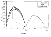
- Fig 8
- shows the effect on arc gap conductance versus time of the novel combination of quenching materials.
-
Fig 2 shows acircuit interrupter 1 comprising a contact with afixed contact 2 and amovable contact 3. The contact is surrounded at least partly by a quenchingchamber 4. Thechamber 4 may comprise one, two, three or fourwalls 5.Fig 2 shows a quenchingchamber 4 with threewalls 5, whereby thewalls 5 define aspace 6 and a contact area 7 within thisspace 6. Anelectrical arc 8 may be generated when thecontacts walls 5 are positioned such that thearc 8 is exposed to thewall 5. Thewalls 5 may comprise more than one level a, b ofwall units 9. As shown infigs 3a and 3b , thewall unit 9 within one level a extend over a width w of thewall 5 along a first axis x and extend along a part or whole length I of thewall 5 along a second axis y being perpendicular to the first axis. The different levels a, b are adjacent to one another. - At least two of the
walls 5a in thechamber 4 are positioned on opposite sides of thespace 6, i.e. on opposite sides of the contact area 7. Seefig 2 to 6 . - Each
wall 5 may comprise one ormore wall units 9 at one or more levels a, b. Eachwall 5 may be divided in two, three, four or fiveunits 9.Fig 4 shows achamber 4 with threewalls 5, whereby eachwall 5 comprises oneunit 9 at one level a.Fig 5 shows achamber 4 with threewalls 5, whereby eachwall 5 comprises twowall units 9 at two levels a, b. - The
wall units 9 comprise quenching material. Thewall units 9 within onewall 5 may comprise the same quenching material (fig 3a ) ordifferent units 9 within onewall 5 may comprise different quenching materials at different levels a, b (fig 3b ). - The quenching material on
opposite walls 5 or sides of thespace 6 in thequenching chamber 4, within at least one level a, comprises quenching material having different quenching capabilities. For example, thechamber 4 may comprise twowalls 5a with three levels a, b, c ofwall units 9, whereby the quenching material comprised in the middle level b on onewall 5a has different quenching capabilities compared to the material comprised in the middle level b on otheropposite wall 5a. The quenching material comprised in one of the other levels a, c ofwall units 9 may be the same or different from the quenching materials comprised in middle level b on either one of theopposite walls 5a. - The quenching
chamber 4 may comprise threedifferent walls third wall 5b may be the same as the quenching material comprised in one of the twoopposite walls 5a. The quenching material comprised in thethird wall 5b, within one level a, may also be the same as the quenching material comprised in both of the twoopposite walls 5a. (Fig 3 ) Thethird wall 5b may thus be divided and comprise different quenching materials within one level a. The quenching material comprised in thethird wall 5b, within one level a, may also be different from the quenching material comprised in bothopposite walls 5a. (Fig 4, 5 ) - The
walls 5 may be aligned with quenching material. Thewalls 5 may also be made of the quenching material. In someinterrupters quenching chambers 4 may be used, whereby thewalls 5 are partly made of quenching material and partly made of other material, which may be aligned with quenching material. - With reference to
fig 1 , the different quenching materials may ablate at different voltages, temperatures or time intervals. Quenching material can be made to ablate under certain conditions. For example, a first ablating or quenching material (area A infig 1 ) may, quickly after opening of the contact, i.e. at the start of the circuit interruption, ablate a vapor gas in thechamber 4. A second material may ablate at increased temperature to cause a cooling effect (area B infig 1 ). Yet further a third material may ablate at a later time interval to neutralise the environment in thespace 6 of the chamber 4 (area C infig 1 ). The vapor gas of the first quenching material will push the electrical arc aside as indicated by the arrow infig 2 . Increasing the length of the arc assists in quenching or extinguishing the arc. A second ablative material may cool the vapor particles in thechamber 4, while a third quenching material may be used to neutralise the vapor in thespace 6 of thechamber 4. - Important is that the quenching
chamber 4 is asymmetrically aligned with quenching material such that the quenching material in thewalls 5a, which are positioned on opposite sides of thespace 6, within at least one level a, have different quenching capabilities. Thus, within at least one level a ofwall unit 9 on onewall 5a, the quenching material is selected from a first material having ablation capability at a start of a circuit interruption, i.e. material which rapidly ablates or a second material having cooling capabilities or a third material having neutralisation capabilities, while the quenching material on theopposite wall 5a, within the same level a is selected from the first or second or third material, but whereby the material on thisopposite walls 5a have different quenching capabilities. In one embodiment, the quenching capabilities of the material on onewall 5a is a mixture of one or more of the first, second and/or third material and the material on theopposite wall 5a is selected from one of the first, second or third material, and has different quenching capabilities. In another embodiment, bothwalls 5a comprise mixtures of one or more of the first, second and/or third material, whereby the capabilities are different on theopposite walls 5a of thespace 6. - The quenching capabilities of the material comprised in the other levels may be the same or different as the capabilities of the material on the one level having the different quenching capabilities on
opposite walls 5a. The quenching materials comprised in the other levels may be different and have different quenching capabilities or the material may be different but have the same quenching capabilities. - The quenching material comprised in the
third wall 5b may be the same or different as the quenching material on twoopposite walls 5a. The different material may have different quenching capabilities or the material may be different but have the same quenching capabilities. For example, the quenchingchamber 4 may comprises threewalls wall walls Fig 4 and 5 ) All possible combinations are included in the scope of this patent application as long as the quenching materials on theopposite walls 5a, at least within one level a ofwall units 9, comprise quenching materials having different quenching capabilities. - A first quenching material configured for rapid ablation at the start of the interruption may be selected depending on the operational conditions for the circuit interrupter and may be selected from the group comprising polyacetals, polyolefins, polyamides, polyacrylates or copolymers or mixtures thereof, and optionally glass materials up to 35 wt% and/or mineral fillers up to 30 wt%.
- Polyacetals may be defined as alkanes comprising an oxy molecule in the main chain. Examples of polyacetals are polyoxymethylene and polyvinylacetal, or copolymers or mixtures thereof. Another example is ethylene vinyl acetate. In one embodiment the first material is polyoxymethylene. In another embodiment the first material is polyvinylacetal. In a further embodiment the material is a copolymer of polyoxymethylene. Examples of polyolefines are polyethylene, polypropylene, polymethylpentene, cycloolefine and polybutylene, or copolymers or mixtures thereof. In one embodiment the first material is polyethylene. In another embodiment the first material is polymethylpentene. In a further embodiment the material is polypropylene. In yet another embodiment the first material is polybutylene.
- Examples of polyamides are
polyamide 6, polyamide 6T,polyamide polyamide polyamide polyamide 12 andpolyamide polyamide 6. In another embodiment the first material is polyamide 6T. In one embodiment the first material ispolyamide polyamide polyamide 12. - Examples of polyacrylates are polymethylmetacrylate, polyethylmetacrylate and polyacrylonitrile. In one embodiment the first material is polymethylmetacrylate. In another embodiment the first material is polyethylmetacrylate.
- The first quenching material, including any one of the single compounds mentioned above, or copolymers or mixture thereof or copolymers of such mixtures, may be combined with glass materials up to 40 wt% and/or mineral fillers up to 30 wt%. Thus, the first quenching material may comprise 0 wt%, or up to 10 wt%, 20 wt% or 30 wt% glass material, or between 5 and 40 wt%, or 5 and 30 wt%, or 5 and 20 wt%. The material may further comprise mineral fillers up to 30 wt%, or 20 wt%, or 10 wt%, or between 1 and 15 wt%, or 5 and 15 wt%. Examples of the first quenching material may be a polyethylene including between 0 to 30 wt% glass material and between 0 to 15 wt% filler. Or polypropylene including between 0 to 30 wt% glass material and between 0 to 15 wt% filler. Or polybutylene including between 0 to 30 wt% glass material and between 0 to 20 wt% filler. Or polymethylpentene including between 0 to 30 wt% glass material and between 0 to 10 wt% filler. Or
polyamide 6 including between 0 to 30 wt% glass material and between 0 to 15 wt% filler. Orpolyamide polyamide polyamide 12 including between 0 to 30 wt% glass material and between 0 to 15 wt% filler. Or polyoxymethylene including between 0 to 30 wt% glass material and between 0 to 20 wt% filler. Or a copolymer of polyoxymethylene including between 0 to 30 wt% glass material and between 0 to 15 wt% filler. Or polymethylmetacrylate including between 0 to 20 wt% glass material and between 0 to 20 wt% filler. - A second quenching material configured for cooling may be ceramic or thermosetting materials selected from the group comprising epoxy and polyesters; or copolymers or mixtures thereof, and optionally including glass materials up to 40 wt% and/ or mineral fillers up to 50 wt%.
- Thermosetting materials may be selected from the group comprising epoxies of bisphenole type, novalak type or alicyclic type, ester type, amino type and phenolic type, or copolymers or mixtures thereof. Examples of bisphenole epoxies may be bisphenole-a type epoxy, bisphenole-f type epoxy.
- Amino type and phenolic type epoxies may be unsaturated polyesters.
- Polyesters may be polyethylenete rphta late or polybutyleneterphtalate, or copolymers or mixtures thereof.
- The second material, including any one of the single compounds mentioned above, or copolymers or mixture thereof, or copolymers of such mixtures, may be combined with glass materials up to 50 wt% and/or mineral fillers up to 50 wt%. Thus, the second quenching material may comprise 0 wt%, or up to 20 wt%, or 30 wt%, or 40 wt%, or 50 wt% glass material, or between 5 and 45 wt%, or 10 and 30 wt%. The material may further comprise mineral fillers up to 40, or 30, or 20, or 10 wt%, or between 5 and 40 wt%, or 10 and 40 wt%, or 5 and 30 wt%. Some examples may be a bisphenole-a type epoxy including between 0 to 40 wt% glass material and between 5 to 40 wt% filler. Or bisphenole-f type epoxy including between 0 to 40 wt% glass material and between 5 to 40 wt% filler. Or amino type unsaturated polyesters including between 0 to 40 wt% glass material and between 5 to 40 wt% filler. Or phenolic type unsaturated polyesters including between 0 to 40 wt% glass material and between 5 to 40 wt% filler. Or novalak type including between 0 to 40 wt% glass material and between 5 to 45 wt% filler. Or alicyclic type including between 0 to 40 wt% glass material and between 5 to 35 wt% filler. Or ester type including between 0 to 40 wt% glass material and between 5 to 45 wt% filler.
- A third quenching material configured for neutralising may be selected from the group comprising polyolefins, polyamids, fluorinated polymers and thermosetting materials, or copolymers or mixtures thereof, and optionally including glass materials up to 40 wt% and/ or mineral fillers up to 50 wt%.
- Polyolefins may be polyethylene, polypropylene, polymethylpentene, polybutylene, or copolymers or mixtures thereof.
- Polyamides may be selected from the
group comprising polyamide 6, polyamide 6T,polyamide polyamide polyamide polyamide 12,polyamide - Fluorinated polymers may be selected from the group comprising polytetrafluoroethylene, polyvinylfluoride, polyvinylidenefluoride, polyperfluoroalkoxy, polyfluorinatedethylenepropylene, or copolymers or mixtures thereof.
- Thermosetting materials may be selected from the group comprising epoxies of bisphenole, novalak or alicyclic or ester type, or copolymers or mixtures thereof, and unsaturated polyester of amino type or phenolic type, or copolymers or mixtures thereof, and optionally glass materials up to 40 wt% and/ or mineral fillers up to 50 wt%.
- Polyester may be polyethyleneterphtalate or polybutyleneterphtalate, or copolymers or mixtures thereof.
- The third quenching material, including any one of the single compounds mentioned above, or copolymers or mixture thereof or copolymers of such mixtures, may be combined with glass materials up to 40 wt% and/or mineral fillers up to 50 wt%. Thus, the third quenching material may comprise 0 wt%, or up to 10 wt%, 20 wt% or 30 wt% glass material, or between 5 and 40 wt%, or 5 and 30 wt%, or 5 and 20 wt%. The material may further comprise mineral fillers up to 50 wt%, 40 wt%, 30 wt%, or 20 wt%, or 10 wt%, or between 1 and 50 wt%, or 5 and 45, or 0 and 40 wt%, or 5 and 35 wt%. Examples of the third quenching material may be a polyethylene including between 0 to 30 wt% glass material and between 0 to 35 wt% filler. Or polypropylene including between 0 to 30 wt% glass material and between 0 to 25 wt% filler. Or polybutylene including between 0 to 30 wt% glass material and between 0 to 20 wt% filler. Or polymethylpentene including between 0 to 30 wt% glass material and between 0 to 10 wt% filler. Or
polyamide 6 including between 0 to 30 wt% glass material and between 0 to 15 wt% filler. Orpolyamide polyamide polyamide 12 including between 0 to 30 wt% glass material and between 0 to 15 wt% filler. Or bisphenole-f type epoxy including between 0 to 40 wt% glass material and between 5 to 40 wt% filler. Or polyvinylidenefluoride including between 0 to 20 wt% glass material and between 0 to 20 wt% filler. - The filler may be metal hydroxides such as compounds of formula Mm(OH)n, wherein M is a metal, m may be 0, 1, 2, 3 or 4 and n may be 0, 1, 2, 3 or 4. In one embodiment m is 1, 2 or 3 and n is 1, 2, 3 or 4. In another embodiment m is 1 or 2 and n is 1, 2 or 3. Examples of metal hydroxides may be selected from the group comprising Ca(OH)2, Mg(OH)2, Zn(OH)2 and Al(OH)3, or hydrates or mixtures thereof. Hydroxides may be advantageously used for neutralising the environment in the quenching chamber. For example a polyamide (
e.g. polyamide e.g. polyamide 11 or 6,10) or a polyacrylate (e.g. polymethylmetacrylate) together with a glass reinforced epoxy may include 10 to 40 wt% Zn(OH)2 and/or its hydrates, or Ca(OH)2 and/or its hydrates. - The filler may also be a carbon oxide releasing compound, which may be a carbon oxide or carbon dioxide or carbon trioxide. Examples are compounds of formula QpHyCOx, wherein Q may be an organic or inorganic compound selected from the group comprising Ca, Na, Mg, Ba and K and p may be 1, 2 or 3, y may be 0, 1 or 2 and x may be 1, 2 or 3. These carbon oxide releasing compound may be selected from the group comprising CaCO3, NaHCO3, KHCO3, MgCO3, BaCO3, CaMg(CO3)2, K2CO3 and Na2CO3, or hydrates or mixtures thereof. For example a polyamide (
e.g. polyamide e.g. polyamide 6, 11 or 12) or a polyolefin (e.g. polyethylene or polymethylpentene) together with a glass reinforced epoxy may include 10 to 40 wt% CaCO3 and/or its hydrates, or BaCO3 and/or its hydrates. Or a polyamide (e.g. polyamides e.g. polyamide - Other fillers that may be used are compound of formula TtRr, selected from oxides, carbides, nitrides, silicides, borides and sulphates, wherein T may be selected from the group comprising Ca, Al, Si, Zr, Ba, Ti, W, Mo, V, Mg, Zn and B, and R may be selected from the group comprising O, SO4, C and N, wherein t may be 1, 2 or 3, and r may be 0, 1, 2, 3 or 4. In one embodiment, t is 1, 2 or 3 and r is 1, 2, 3 or 4. The compound of formula TtRr may be selected from the group of oxides comprising CaO, MgO, ZnO, BaO, ZrO2, SiO2, TiO2, ZrSiO4, MgAl2O4 and Al2O3. Or the compound of formula TtRr may be selected from the group of nitrides comprising BN, AIN, CN, SiN, TiN and Si3N4. Or the compound of formula TtRr may be selected from the group of carbides comprising SiC, TiC, ZrC, WC, Mo2C, VC and B4C. Or the compound of formula TtRr may be selected from the group of silicides comprising WSi2 and MoSi2. Or the compound of formula TtRr may be selected from the group of borides comprising TiB2 and ZrB2. Or the compound of formula TtRr may be selected from the group of sulphates comprising CaSO4, MgSO4 and Al2(SO4)3 For example the quenching material may comprise a polyolefin with 2 to 7 wt% of a boride filler such as polymethylpentene with 3 wt% TiB2. Or polybutylene with 7% ZrB2. Or polypropylene with 5 wt% TiB2. Or a polyolefin with 2 to 7 wt% of an oxide filler such as polymethylpentene with 3 wt% MgO. Or polybutylene with 7% ZnO. Or a polyolefin with 2 to 7 wt% of a nitride filler such as polybutylene with 5 wt% TiN, or polypropylene with 5 wt% BN, or polymethylpentene with 5 wt% AlN. Or a polyolefin with 2 to 7 wt% of a carbide filler such as polypropylene with 5 wt% SiC, or polybutylene with 5 wt% B4C. Or a polyolefin with 2 to 7 wt% of a silicide filler such as polybutylene with 5 wt% WSi2, or polypropylene with 5 wt% MoSi2. Or a polyolefin with 2 to 7 wt% of a sulphate filler such as polybutylene with 5 wt% CaSO4, or polyethylene with 5 wt% MgSO4.
- The quenching material may also comprise a polyamide with 2 to 7 wt% of a boride filler, such as
polyamide 6 orpolyamide 12 with 5 wt% TiB2. Or a polyamide with 3 to 7 wt% of an oxide filler such as polyamide 6.6 with 5 wt% Al2O3 Or a polyamide with 2 to 7 wt% of a nitride filler such aspolyamide 6 or polyamide 6.6 with 5 wt% AIN, orpolyamide 12 with 5 wt% BN. or polyamide 6T with 5 wt% Si3N4. Or a polyamide with 2 to 7 wt% of a carbide filler such aspolyamide polyamide 12 with 5 wt% SiC, or polyamide 11 with 5 wt% B4C. Or a polyamide with 2 to 7 wt% of a silicide filler such as polyamide 11 with 5 wt% WSi2, orpolyamide 12 with 5 wt% MoSi2. Or a polyamide with 2 to 7 wt% of a sulphate filler such aspolyamide 6 with 5 wt% CaSO4, orpolyamide - The quenching material may also comprise a fluorinated polymers with 2 to 7 wt% of a boride filler, such as polytetrafluoroethylene with 5 wt% TiB2. Or a fluorinated polymers with 3 to 7 wt% of an oxide filler such as polyperfluoroalkoxy with 5 wt% Al2O3 Or a fluorinated polymers with 2 to 7 wt% of a nitride filler such as polytetrafluoroethylene with 5 wt% AIN, or
polyvinylidenefluoride 5 wt% BN, or polyperfluoroalkoxy 5 wt% Si3N4. Or a fluorinated polymers with 2 to 7 wt% of a carbide filler such as polyperfluoroalkoxy with 5 wt% SiC, or polyvinylidenefluoride with 5 wt% B4C. Or a fluorinated polymers with 2 to 7 wt% of a silicide filler such as polyfluorinatedethylenepropylene with 5 wt% WSi2, orpolyvinylidenefluoride 5 wt% MoSi2. Or a fluorinated polymers with 2 to 7 wt% of a sulphate filler such as polyfluorinatedethylenepropylene with 5 wt% CaSO4, or polyvinylfluoride with 5 wt% MgSO4. - The quenching material may also comprise a thermosetting material with 2 to 7 wt% of a boride filler, such as bisphenole-f type epoxy with 5 wt% ZrB2, or novalak type with 5 wt% TiB2. Or a thermosetting material with 3 to 7 wt% of an oxide filler such as alicyclic type epoxy with 5 wt% Al2O3 Or a thermosetting material with 2 to 7 wt% of a nitride filler such as amino type unsaturated polyester epoxy with 5 wt% AIN, or
alicyclic type 5 wt% BN, or bisphenole-atype epoxy 5 wt% Si3N4. Or a thermosetting material with 2 to 7 wt% of a carbide filler such as alicyclic type epoxy with 5 wt% SiC, or bisphenole-f type epoxy with 5 wt% B4C. Or a thermosetting material with 2 to 7 wt% of a silicide filler such as alicyclic type epoxy with 5 wt% WSi2, or ester type epoxy 5 wt% MoSi2. Or a thermosetting material with 2 to 7 wt% of a sulphate filler such as phenolic type unsaturated polyester epoxy with 5 wt% CaSO4, or bisphenole-a type epoxy with 5 wt% MgSO4. - The filler may also be any mixture of any of the fillers mentioned above. The mineral filler may be selected from CaO, MgO, ZnO, BaO, ZrO2, SiO2, TiO2, ZrSiO4, MgAl2O4, Al2O3, BN, AlN, CN, SiN, TiN, Si3N4, SiC, TiC, ZrC, WC, Mo2C, VC, B4C, WSi2 and MoSi2, TiB2, ZrB2, CaSO4, MgSO4, Al2(SO4)3, Ca(OH)2, Mg(OH)2, Zn(OH)2, Al(OH)3, CaCO3, NaHCO3, KHCO3, MgCO3, BaCO3, CaMg(CO3)2, K2CO3 and Na2CO3 or hydrates or mixtures thereof. Or the mineral filler may be selected from MgO, ZnO, Al2O3, BN, AIN, TiN, Si3N4, SiC, B4C, Ca(OH)2, Mg(OH)2, Al(OH)3, Ca-CO3, MgCO3, BaCO3 and CaMg(CO3)2, or hydrates or mixtures thereof.
- The glass material may be present in weight percentages of the total weight of the quenching material in a range between 5 to 45 wt%, or 15 to 35 wt%, or 20 to 35 wt%, or 25 to 35 wt%, or 5 to 30 wt%, or 10 to 30 wt%, or 15 to 30 wt%.
- The filler may be present in weight percentages of the total weight of the quenching material in a range between 5 to 45 wt%, or 5 to 40 wt%, or 5 to 30 wt%, or 0 to 25 wt%, or 5 to 25 wt%, or 0 to 15 wt%, or 0 to 10 wt%.
- The quenching material may comprise any of the compounds or any combination of any of the compounds at any percentage and between any of the ranges mentioned in this application.
- The quenching
chamber 4 may comprise at least twoopposite walls 5a, whereby, within one level a, onewall 5a comprises polyoxymethylene and optionally glass materials up to 35 wt% and/or mineral fillers up to 30 wt% and theopposite wall 5a comprises polymethylpentene and optionally glass materials up to 40 wt% and/or mineral fillers up to 50 wt%. In one embodiment thewalls 5a comprise 0 to 40 wt%, or 10 to 35 wt%, or 25 to 35 wt% glass material and 5 to 50 wt%, or 0 to 30 wt%, or 0 to 20 wt%, or 0 to 10 wt% mineral fillers. The mineral filler may be selected from the group comprising CaO, MgO, ZnO, BaO, ZrO2, SiO2, TriO2, ZrSiO4, MgAl2O4, Al2O3, BN, AlN, CN, SiN, TiN, Si3N4, SiC, TiC, ZrC, WC, Mo2C, VC, B4C, WSi2 and MoSi2, TiB2, ZrB2, CaSO4, MgSO4, Al2(SO4)3, Ca(OH)2, Mg(OH)2, Zn(OH)2, Al(OH)3, CaCO3, NaHCO3, KHCO3, MgCO3, BaCO3, CaMg(CO3)2, K2CO3 and Na2CO3, or hydrates or mixtures thereof. - The quenching
chamber 4 may comprise at least twoopposite walls 5a, whereby, within one level a, onewall 5a comprises polyoxymethylene and optionally glass materials up to 35 wt% and/or mineral fillers up to 30 wt% and theopposite wall 5a comprises polyethylene, or polypropylene and optionally glass materials up to 40 wt% and/ or mineral fillers up to 50 wt%. In one embodiment thewalls 5a comprise 0 to 40 wt%, or 10 to 35 wt%, or 25 to 35 wt% glass material and 5 to 50 wt%, or 0 to 30 wt%, or 0 to 20 wt%, or 0 to 10 wt% mineral fillers. The mineral filler may be selected from the group comprising CaO, MgO, ZnO, BaO, ZrO2, SiO2, TiO2, ZrSiO4, MgAl2O4, Al2O3, BN, AlN, CN, SiN, TiN, Si3N4, SiC, TiC, ZrC, WC, Mo2C, VC, B4C, WSi2 and MoSi2, TiB2, ZrB2, CaSO4, MgSO4, Al2(SO4)3, Ca(OH)2, Mg(OH)2, Zn(OH)2 and Al(OH)3, CaCO3, NaHCO3, KHCO3, MgCO3, BaCO3, CaMg(CO3)2, K2CO3 and Na2CO3 or hydrates or mixtures thereof. In one embodiment the polyethylene is replaced by polypropylene. - The quenching
chamber 4 may comprise at least twoopposite walls 5a, whereby, within one level a, onewall 5a comprises polyoxymethylene and optionally glass materials up to 35 wt% and/or mineral fillers up to 30 wt% and theopposite wall 5a comprises a polyamide and optionally glass materials up to 40 wt% and/ or mineral fillers up to 50 wt%. In one embodiment the polyamide ispolyamide walls 5a comprise 0 to 40 wt%, or 10 to 35 wt%, or 25 to 35 wt% glass material and 5 to 50 wt%, or 0 to 30 wt%, or 0 to 20 wt%, or 0 to 10 wt% mineral fillers. The mineral filler may be selected from the group comprising CaO, MgO, ZnO, BaO, ZrO2, SiO2, TiO2, ZrSiO4, MgAl2O4, Al2O3, BN, AlN, CN, SiN, TiN, Si3N4, SiC, TiC, ZrC, WC, Mo2C, VC, B4C, WSi2 and MoSi2, TiB2, ZrB2, CaSO4, MgSO4, Al2(SO4)3, Ca(OH)2, Mg(OH)2, Zn(OH)2 and Al(OH)3, CaCO3, NaHCO3, KHCO3, MgCO3, BaCO3, CaMg(CO3)2, K2CO3 and Na2CO3 or hydrates or mixtures thereof. - The invention relates to use of a combination of quenching materials, whereby the quenching materials are selected from poly-oxymethylene or copolymer thereof and optionally glass materials up to 35 wt% and/or mineral fillers up to 30 wt% combined with polymethylpentene, or polyethylene, or polypropylene, or
polyamide 6, orpolyamide polyamide 12, and optionally glass materials up to 40 wt% and/or mineral fillers up to 50 wt%, for extinguishing or quenching an electrical arc between a fixed contact and a movable contact of a contact positioned in a quenching chamber. The percentages for the glass materials and mineral fillers may be replaced by any of the percentages or any of the ranges of percentages mentioned above. - The quenching
chamber 4 as described above may be used in a method for extinguishing or quenching an electrical arc between a fixed contact and a movable contact of a contact positioned in a quenching chamber. Any combinations of any feature described above may be used in thechamber 4 and the method. Thechamber 4 may further comprise a vent and the like to improve the quenching performance of thechamber 4. - Experiments were performed in a RLC circuit under damped conditions using a capacitor bank. The experiments were performed in quenching chambers, whereby one
wall 5a comprised polyoxymethylene (POM) and theopposite wall 5a comprised glass reinforced (25 wt%)polyamide 12 containing 5 wt% BN as a filler (PAGFBN). The experiment was repeated using POM or PAGFBN as quenching material on thewalls 5a on both sides of thespace 6. - The arc voltages for the different chambers are shown in
Fig 7 . The mean arc voltage of the combined asymmetric positioned material is clearly higher compared with the mean voltage from either of the materials. The capacitor bank was charged at different voltage levels in order to simulate different operational conditions. The time at which the arc voltage starts to increase is an indication of the beginning of the pressure build up, and the moment that the material starts the ablation. Comparison of the times indicates that the chamber comprising the combination of the asymmetric positioned materials has a faster increase of the voltage (point F). The voltage remains higher in thenew chamber 4 according to the invention as shown in points H. The results show that combining the materials in thechamber 4 allows controlling the time at which the gassing of the material takes place. - The effect of the same materials on gap conductance was measured in the capacitor bank. (
Fig 8 ) These results show that thechamber 4 comprising the combination of the asymmetric positioned materials, has a lower gap conductance compared to the other two chambers (Point L inFig 8 ). Also shown is that the gap conductance is lower during most of the breaking time. - The present invention is not limited to the embodiments disclosed but may be varied and modified within the scope of the following claims.
Claims (15)
- A quenching chamber (4) for a circuit interrupter (1) comprising a space (6), and at least two walls (5) at least partially enclosing the space (6) and positioned on opposite sides of the space (6), wherein the quenching chamber (4) is configured to comprise, in the space (6), a switch having a fixed contact (2) and a movable contact (3), between which contacts (2, 3) an arc can be generated, each wall (5) of the quenching chamber (4) comprises one or more levels (a) of wall units (9), whereby the wall unit (9) within one level (a) extend over a width (w) of the wall (5) along a first axis (x) and extend along a part or whole length (I) of the wall (5) along a second axis (y) being perpendicular to the first axis, and whereby each wall unit (9) comprises quenching material, and
characterised in that
the wall units (9) on opposite sides of the space (6) within the same level (a) comprise quenching material having different quenching capabilities. - The quenching chamber (4) according to claim 1, characterised in that the quenching material is selected from a first material having ablation capability at a start of a circuit interruption, a second material having cooling capabilities and a third material having neutralisation capabilities, or any mixtures thereof.
- The quenching chamber (4) according to claim 2, characterised in that the first material ablates faster than the second and third material, and the second material cools the space (6) faster than the first and third material, and the third material neutralises faster than the first and second material.
- The quenching chamber (4) according to any one of claims 1 to 3, characterised in that the at least two walls (5) comprise two levels (a, b) of wall units (9).
- The quenching chamber (4) according to any one of claims 1 to 3, characterised in that the at least two walls (5) comprise three levels (a, b, c) of wall units (9), whereby the quenching materials comprised in the middle level (b) has different quenching capabilities from the quenching material comprised in at least one of the other levels (a, c) of wall units (9).
- The quenching chamber (4) according to any one of claims 1 to 3, characterised in that at least three different walls (5) are present in the chamber (4), whereby, within one level (a), the quenching material comprised in the third wall may have the same or different quenching capabilities as the quenching material comprised in one or in both of the two opposite wall (5a).
- The quenching chamber (4) according to any one of claims 1 to 6, characterised in that the first material is selected from the group comprising polyacetals, polyolefins, polyamides and polyacrylates, or copolymers or mixtures thereof, and optionally glass materials up to 35 wt% and/or mineral fillers up to 30 wt%.
- The quenching chamber (4) according to any one of claims 1 to 6, characterised in that the second material is selected from the group comprising ceramic and thermosetting materials selected from the group comprising epoxy and polyesters, or co-polymers or mixtures thereof, and optionally including glass materials up to 40 wt% and/ or mineral fillers up to 50 wt%.
- The quenching chamber (4) according to any one of claims 5 to 6, characterised in that the third material is selected from the group comprising polyolefins, polyamides, fluorinated polymers and thermosetting polymers, or copolymers or mixtures thereof, and optionally including glass materials up to 40 wt% and/or mineral fillers up to 50 wt%.
- The quenching chamber (4) according to any one of claims 7 to 9, characterised in that the filler is selected from the group comprising
compounds of formula Mm(OH)n, wherein M is a metal, m is 0, 1, 2 or 3, and n is 0, 1, 2, 3 or 4, and
compounds of formula QpHyCOx, wherein Q is selected from the group comprising Ca, Na, Mg, Ba and K and p is 0, 1, 2 or 3, y is 0, 1 or 2 and x is 1, 2 or 3, and
compound of formula TtRr, wherein T is selected from the group comprising Ca, Al, Si, Zr, Ba, Ti, W, Mo, V, Mg, Zn and B, and R is selected from the group comprising O, SO4, C and N, wherein t is 1, 2 or 3, and r is 0, 1, 2, 3 or 4,
or hydrates or mixtures thereof. - The quenching chamber (4) according to any one of claims 7 to 9, characterised in that the filler is selected from the group comprising CaO, MgO, ZnO, BaO, ZrO2, SiO2, TiO2, ZrSiO4, MgAl2O4, Al2O3, BN, AlN, CN, SiN, TiN, Si3N4, SiC, TiC, ZrC, WC, Mo2C, VC, B4C, WSi2 and MoSi2, TiB2, ZrB2, CaSO4, MgSO4, Al2(SO4)3, Ca(OH)2, Mg(OH)2, Zn(OH)2 and Al(OH)3, CaCO3, NaHCO3, KHCO3, MgCO3, BaCO3, CaMg(CO3)2, K2CO3 and Na2CO3, or hydrates or mixtures thereof.
- The quenching chamber (4) according to claim 1, characterised in comprising at least two opposite walls (5a) whereby, within one level (a), one wall (5a) comprises polyoxymethylene and optionally glass materials up to 35 wt% and/or mineral fillers up to 30 wt% and the opposite wall (5a) comprises polymethylpentene or polyamide 6, 6,6, 11 or 12 and optionally glass materials up to 40 wt% and/or mineral fillers up to 50 wt%.
- A switch comprising the quenching chamber (4) according to any one of claims 1 to 12.
- A method for quenching an electrical arc between a fixed contact (2) and a movable contact (3) comprised in a switch, whereby the switch is positioned in a quenching chamber (4), comprising a space (6), and at least two walls (5) at least partially enclosing the space (6) and positioned on opposite sides of the space (6), and whereby the contacts (2, 3) are provided in the space (6) and between which an arc can be generated, and each wall (5) of the quenching chamber (4) comprises one or more levels (a) of wall units (9), whereby the wall unit (9) within one level (a) extend over a width (w) of the wall (5) along a first axis (x) and extend along a part or whole length (l) of the wall (5) along a second axis (y) being perpendicular to the first axis, and whereby each wall unit (9) comprises quenching material,
characterised in that the wall units (9) on opposite sides of the space (6) within the same level (a) comprise quenching material having different quenching capabilities. - The method according to claim 14, characterised in that the quenching material comprises quenching capabilities selected from a first material having ablation capability at a start of a circuit interruption, a second material having cooling capabilities and a third material having neutralisation capabilities, or any mixtures thereof.
Applications Claiming Priority (1)
| Application Number | Priority Date | Filing Date | Title |
|---|---|---|---|
| PCT/EP2011/064881 WO2013029657A1 (en) | 2011-08-30 | 2011-08-30 | A quenching chamber for a circuit interrupter |
Publications (2)
| Publication Number | Publication Date |
|---|---|
| EP2751824A1 EP2751824A1 (en) | 2014-07-09 |
| EP2751824B1 true EP2751824B1 (en) | 2015-10-14 |
Family
ID=44511025
Family Applications (1)
| Application Number | Title | Priority Date | Filing Date |
|---|---|---|---|
| EP11748691.0A Active EP2751824B1 (en) | 2011-08-30 | 2011-08-30 | A quenching chamber for a circuit interrupter |
Country Status (2)
| Country | Link |
|---|---|
| EP (1) | EP2751824B1 (en) |
| WO (1) | WO2013029657A1 (en) |
Families Citing this family (2)
| Publication number | Priority date | Publication date | Assignee | Title |
|---|---|---|---|---|
| CN111087233A (en) * | 2019-12-18 | 2020-05-01 | 佛山科学技术学院 | Antibacterial ceramic material |
| CN114806073B (en) * | 2022-06-14 | 2023-06-09 | 兰州中科聚润新材料有限公司 | A kind of polyoxymethylene copolymer composite material and its preparation method, leather bowl |
Family Cites Families (4)
| Publication number | Priority date | Publication date | Assignee | Title |
|---|---|---|---|---|
| TW293130B (en) | 1994-03-10 | 1996-12-11 | Mitsubishi Electric Corp | |
| US5589672A (en) | 1994-06-14 | 1996-12-31 | Fuji Electric Co., Ltd. | Circuit breaker with arc quenching device and vent |
| US20080061037A1 (en) | 2006-09-07 | 2008-03-13 | Thangavelu Asokan | Composite arc suppression device |
| US20080073326A1 (en) | 2006-09-21 | 2008-03-27 | Thangavelu Asokan | Ablative Circuit Interruption Device |
-
2011
- 2011-08-30 WO PCT/EP2011/064881 patent/WO2013029657A1/en not_active Ceased
- 2011-08-30 EP EP11748691.0A patent/EP2751824B1/en active Active
Also Published As
| Publication number | Publication date |
|---|---|
| EP2751824A1 (en) | 2014-07-09 |
| WO2013029657A1 (en) | 2013-03-07 |
Similar Documents
| Publication | Publication Date | Title |
|---|---|---|
| KR101386582B1 (en) | A circuit braker | |
| KR20140023318A (en) | Gas-insulated high-voltage circuit breaker | |
| US20070205182A1 (en) | Switching chamber and heavy-duty circuit breaker | |
| WO2014069195A1 (en) | Gas circuit breaker | |
| KR101860348B1 (en) | Vacuum interrupter for vacuum circuit breaker | |
| EP2751824A1 (en) | A quenching chamber for a circuit interrupter | |
| CN101496123B (en) | Insulating nozzle, comprising a first material and a second material | |
| CN1901124A (en) | Gas insulation switch | |
| JP2004164994A (en) | Switch | |
| CN113544809B (en) | Circuit breaker arrangement | |
| EP3840005B1 (en) | Two way piston interrupter | |
| KR102823259B1 (en) | Nozzle device of gas insulated circuit breaker | |
| JP4634259B2 (en) | Puffer type gas circuit breaker | |
| US20080073326A1 (en) | Ablative Circuit Interruption Device | |
| JP5286569B2 (en) | Puffer type gas circuit breaker | |
| JP2006059758A (en) | Circuit breaker arc extinguishing device | |
| KR100864125B1 (en) | Circuit breaker | |
| KR100345691B1 (en) | Hybrid-extinction type gas circuit breaker | |
| JP2918752B2 (en) | Switch | |
| JPH04315721A (en) | Buffer type gas-blast circuit breaker | |
| US20080061037A1 (en) | Composite arc suppression device | |
| JPH04359817A (en) | Switch device | |
| JP6340151B2 (en) | Gas circuit breaker | |
| JP2996807B2 (en) | Switch | |
| JP3657489B2 (en) | Air switch |
Legal Events
| Date | Code | Title | Description |
|---|---|---|---|
| PUAI | Public reference made under article 153(3) epc to a published international application that has entered the european phase |
Free format text: ORIGINAL CODE: 0009012 |
|
| 17P | Request for examination filed |
Effective date: 20140331 |
|
| AK | Designated contracting states |
Kind code of ref document: A1 Designated state(s): AL AT BE BG CH CY CZ DE DK EE ES FI FR GB GR HR HU IE IS IT LI LT LU LV MC MK MT NL NO PL PT RO RS SE SI SK SM TR |
|
| DAX | Request for extension of the european patent (deleted) | ||
| GRAP | Despatch of communication of intention to grant a patent |
Free format text: ORIGINAL CODE: EPIDOSNIGR1 |
|
| INTG | Intention to grant announced |
Effective date: 20150413 |
|
| GRAS | Grant fee paid |
Free format text: ORIGINAL CODE: EPIDOSNIGR3 |
|
| GRAA | (expected) grant |
Free format text: ORIGINAL CODE: 0009210 |
|
| AK | Designated contracting states |
Kind code of ref document: B1 Designated state(s): AL AT BE BG CH CY CZ DE DK EE ES FI FR GB GR HR HU IE IS IT LI LT LU LV MC MK MT NL NO PL PT RO RS SE SI SK SM TR |
|
| REG | Reference to a national code |
Ref country code: GB Ref legal event code: FG4D |
|
| REG | Reference to a national code |
Ref country code: AT Ref legal event code: REF Ref document number: 755668 Country of ref document: AT Kind code of ref document: T Effective date: 20151015 Ref country code: CH Ref legal event code: EP |
|
| REG | Reference to a national code |
Ref country code: IE Ref legal event code: FG4D |
|
| REG | Reference to a national code |
Ref country code: DE Ref legal event code: R096 Ref document number: 602011020617 Country of ref document: DE |
|
| REG | Reference to a national code |
Ref country code: NL Ref legal event code: MP Effective date: 20151014 |
|
| REG | Reference to a national code |
Ref country code: LT Ref legal event code: MG4D |
|
| REG | Reference to a national code |
Ref country code: AT Ref legal event code: MK05 Ref document number: 755668 Country of ref document: AT Kind code of ref document: T Effective date: 20151014 |
|
| PG25 | Lapsed in a contracting state [announced via postgrant information from national office to epo] |
Ref country code: IS Free format text: LAPSE BECAUSE OF FAILURE TO SUBMIT A TRANSLATION OF THE DESCRIPTION OR TO PAY THE FEE WITHIN THE PRESCRIBED TIME-LIMIT Effective date: 20160214 Ref country code: HR Free format text: LAPSE BECAUSE OF FAILURE TO SUBMIT A TRANSLATION OF THE DESCRIPTION OR TO PAY THE FEE WITHIN THE PRESCRIBED TIME-LIMIT Effective date: 20151014 Ref country code: NL Free format text: LAPSE BECAUSE OF FAILURE TO SUBMIT A TRANSLATION OF THE DESCRIPTION OR TO PAY THE FEE WITHIN THE PRESCRIBED TIME-LIMIT Effective date: 20151014 Ref country code: NO Free format text: LAPSE BECAUSE OF FAILURE TO SUBMIT A TRANSLATION OF THE DESCRIPTION OR TO PAY THE FEE WITHIN THE PRESCRIBED TIME-LIMIT Effective date: 20160114 Ref country code: ES Free format text: LAPSE BECAUSE OF FAILURE TO SUBMIT A TRANSLATION OF THE DESCRIPTION OR TO PAY THE FEE WITHIN THE PRESCRIBED TIME-LIMIT Effective date: 20151014 Ref country code: LT Free format text: LAPSE BECAUSE OF FAILURE TO SUBMIT A TRANSLATION OF THE DESCRIPTION OR TO PAY THE FEE WITHIN THE PRESCRIBED TIME-LIMIT Effective date: 20151014 |
|
| PG25 | Lapsed in a contracting state [announced via postgrant information from national office to epo] |
Ref country code: RS Free format text: LAPSE BECAUSE OF FAILURE TO SUBMIT A TRANSLATION OF THE DESCRIPTION OR TO PAY THE FEE WITHIN THE PRESCRIBED TIME-LIMIT Effective date: 20151014 Ref country code: LV Free format text: LAPSE BECAUSE OF FAILURE TO SUBMIT A TRANSLATION OF THE DESCRIPTION OR TO PAY THE FEE WITHIN THE PRESCRIBED TIME-LIMIT Effective date: 20151014 Ref country code: PT Free format text: LAPSE BECAUSE OF FAILURE TO SUBMIT A TRANSLATION OF THE DESCRIPTION OR TO PAY THE FEE WITHIN THE PRESCRIBED TIME-LIMIT Effective date: 20160215 Ref country code: PL Free format text: LAPSE BECAUSE OF FAILURE TO SUBMIT A TRANSLATION OF THE DESCRIPTION OR TO PAY THE FEE WITHIN THE PRESCRIBED TIME-LIMIT Effective date: 20151014 Ref country code: FI Free format text: LAPSE BECAUSE OF FAILURE TO SUBMIT A TRANSLATION OF THE DESCRIPTION OR TO PAY THE FEE WITHIN THE PRESCRIBED TIME-LIMIT Effective date: 20151014 Ref country code: GR Free format text: LAPSE BECAUSE OF FAILURE TO SUBMIT A TRANSLATION OF THE DESCRIPTION OR TO PAY THE FEE WITHIN THE PRESCRIBED TIME-LIMIT Effective date: 20160115 Ref country code: SE Free format text: LAPSE BECAUSE OF FAILURE TO SUBMIT A TRANSLATION OF THE DESCRIPTION OR TO PAY THE FEE WITHIN THE PRESCRIBED TIME-LIMIT Effective date: 20151014 Ref country code: AT Free format text: LAPSE BECAUSE OF FAILURE TO SUBMIT A TRANSLATION OF THE DESCRIPTION OR TO PAY THE FEE WITHIN THE PRESCRIBED TIME-LIMIT Effective date: 20151014 |
|
| REG | Reference to a national code |
Ref country code: DE Ref legal event code: R097 Ref document number: 602011020617 Country of ref document: DE |
|
| PG25 | Lapsed in a contracting state [announced via postgrant information from national office to epo] |
Ref country code: CZ Free format text: LAPSE BECAUSE OF FAILURE TO SUBMIT A TRANSLATION OF THE DESCRIPTION OR TO PAY THE FEE WITHIN THE PRESCRIBED TIME-LIMIT Effective date: 20151014 |
|
| PLBE | No opposition filed within time limit |
Free format text: ORIGINAL CODE: 0009261 |
|
| STAA | Information on the status of an ep patent application or granted ep patent |
Free format text: STATUS: NO OPPOSITION FILED WITHIN TIME LIMIT |
|
| REG | Reference to a national code |
Ref country code: FR Ref legal event code: PLFP Year of fee payment: 6 |
|
| PG25 | Lapsed in a contracting state [announced via postgrant information from national office to epo] |
Ref country code: SM Free format text: LAPSE BECAUSE OF FAILURE TO SUBMIT A TRANSLATION OF THE DESCRIPTION OR TO PAY THE FEE WITHIN THE PRESCRIBED TIME-LIMIT Effective date: 20151014 Ref country code: SK Free format text: LAPSE BECAUSE OF FAILURE TO SUBMIT A TRANSLATION OF THE DESCRIPTION OR TO PAY THE FEE WITHIN THE PRESCRIBED TIME-LIMIT Effective date: 20151014 Ref country code: RO Free format text: LAPSE BECAUSE OF FAILURE TO SUBMIT A TRANSLATION OF THE DESCRIPTION OR TO PAY THE FEE WITHIN THE PRESCRIBED TIME-LIMIT Effective date: 20151014 Ref country code: EE Free format text: LAPSE BECAUSE OF FAILURE TO SUBMIT A TRANSLATION OF THE DESCRIPTION OR TO PAY THE FEE WITHIN THE PRESCRIBED TIME-LIMIT Effective date: 20151014 Ref country code: DK Free format text: LAPSE BECAUSE OF FAILURE TO SUBMIT A TRANSLATION OF THE DESCRIPTION OR TO PAY THE FEE WITHIN THE PRESCRIBED TIME-LIMIT Effective date: 20151014 |
|
| 26N | No opposition filed |
Effective date: 20160715 |
|
| PG25 | Lapsed in a contracting state [announced via postgrant information from national office to epo] |
Ref country code: SI Free format text: LAPSE BECAUSE OF FAILURE TO SUBMIT A TRANSLATION OF THE DESCRIPTION OR TO PAY THE FEE WITHIN THE PRESCRIBED TIME-LIMIT Effective date: 20151014 |
|
| PG25 | Lapsed in a contracting state [announced via postgrant information from national office to epo] |
Ref country code: BE Free format text: LAPSE BECAUSE OF FAILURE TO SUBMIT A TRANSLATION OF THE DESCRIPTION OR TO PAY THE FEE WITHIN THE PRESCRIBED TIME-LIMIT Effective date: 20151014 |
|
| REG | Reference to a national code |
Ref country code: DE Ref legal event code: R081 Ref document number: 602011020617 Country of ref document: DE Owner name: ABB SCHWEIZ AG, CH Free format text: FORMER OWNER: ABB TECHNOLOGY AG, ZUERICH, CH |
|
| PG25 | Lapsed in a contracting state [announced via postgrant information from national office to epo] |
Ref country code: MC Free format text: LAPSE BECAUSE OF FAILURE TO SUBMIT A TRANSLATION OF THE DESCRIPTION OR TO PAY THE FEE WITHIN THE PRESCRIBED TIME-LIMIT Effective date: 20151014 |
|
| REG | Reference to a national code |
Ref country code: CH Ref legal event code: PL |
|
| GBPC | Gb: european patent ceased through non-payment of renewal fee |
Effective date: 20160830 |
|
| PG25 | Lapsed in a contracting state [announced via postgrant information from national office to epo] |
Ref country code: CH Free format text: LAPSE BECAUSE OF NON-PAYMENT OF DUE FEES Effective date: 20160831 Ref country code: LI Free format text: LAPSE BECAUSE OF NON-PAYMENT OF DUE FEES Effective date: 20160831 |
|
| REG | Reference to a national code |
Ref country code: IE Ref legal event code: MM4A |
|
| PG25 | Lapsed in a contracting state [announced via postgrant information from national office to epo] |
Ref country code: IE Free format text: LAPSE BECAUSE OF NON-PAYMENT OF DUE FEES Effective date: 20160830 Ref country code: GB Free format text: LAPSE BECAUSE OF NON-PAYMENT OF DUE FEES Effective date: 20160830 |
|
| REG | Reference to a national code |
Ref country code: FR Ref legal event code: PLFP Year of fee payment: 7 |
|
| PG25 | Lapsed in a contracting state [announced via postgrant information from national office to epo] |
Ref country code: LU Free format text: LAPSE BECAUSE OF NON-PAYMENT OF DUE FEES Effective date: 20160830 |
|
| PG25 | Lapsed in a contracting state [announced via postgrant information from national office to epo] |
Ref country code: CY Free format text: LAPSE BECAUSE OF FAILURE TO SUBMIT A TRANSLATION OF THE DESCRIPTION OR TO PAY THE FEE WITHIN THE PRESCRIBED TIME-LIMIT Effective date: 20151014 Ref country code: HU Free format text: LAPSE BECAUSE OF FAILURE TO SUBMIT A TRANSLATION OF THE DESCRIPTION OR TO PAY THE FEE WITHIN THE PRESCRIBED TIME-LIMIT; INVALID AB INITIO Effective date: 20110830 |
|
| PG25 | Lapsed in a contracting state [announced via postgrant information from national office to epo] |
Ref country code: MT Free format text: LAPSE BECAUSE OF NON-PAYMENT OF DUE FEES Effective date: 20160831 Ref country code: MK Free format text: LAPSE BECAUSE OF FAILURE TO SUBMIT A TRANSLATION OF THE DESCRIPTION OR TO PAY THE FEE WITHIN THE PRESCRIBED TIME-LIMIT Effective date: 20151014 |
|
| PG25 | Lapsed in a contracting state [announced via postgrant information from national office to epo] |
Ref country code: BG Free format text: LAPSE BECAUSE OF FAILURE TO SUBMIT A TRANSLATION OF THE DESCRIPTION OR TO PAY THE FEE WITHIN THE PRESCRIBED TIME-LIMIT Effective date: 20151014 |
|
| REG | Reference to a national code |
Ref country code: FR Ref legal event code: PLFP Year of fee payment: 8 |
|
| REG | Reference to a national code |
Ref country code: FR Ref legal event code: TP Owner name: ABB SCHWEIZ AG, CH Effective date: 20180912 |
|
| PG25 | Lapsed in a contracting state [announced via postgrant information from national office to epo] |
Ref country code: AL Free format text: LAPSE BECAUSE OF FAILURE TO SUBMIT A TRANSLATION OF THE DESCRIPTION OR TO PAY THE FEE WITHIN THE PRESCRIBED TIME-LIMIT Effective date: 20151014 Ref country code: TR Free format text: LAPSE BECAUSE OF FAILURE TO SUBMIT A TRANSLATION OF THE DESCRIPTION OR TO PAY THE FEE WITHIN THE PRESCRIBED TIME-LIMIT Effective date: 20151014 |
|
| PGFP | Annual fee paid to national office [announced via postgrant information from national office to epo] |
Ref country code: DE Payment date: 20250820 Year of fee payment: 15 |
|
| PGFP | Annual fee paid to national office [announced via postgrant information from national office to epo] |
Ref country code: IT Payment date: 20250825 Year of fee payment: 15 |
|
| PGFP | Annual fee paid to national office [announced via postgrant information from national office to epo] |
Ref country code: FR Payment date: 20250829 Year of fee payment: 15 |