EP2751609B1 - Head mounted display with iris scan profiling - Google Patents
Head mounted display with iris scan profiling Download PDFInfo
- Publication number
- EP2751609B1 EP2751609B1 EP12827964.3A EP12827964A EP2751609B1 EP 2751609 B1 EP2751609 B1 EP 2751609B1 EP 12827964 A EP12827964 A EP 12827964A EP 2751609 B1 EP2751609 B1 EP 2751609B1
- Authority
- EP
- European Patent Office
- Prior art keywords
- user
- display
- eye
- optical system
- display optical
- Prior art date
- Legal status (The legal status is an assumption and is not a legal conclusion. Google has not performed a legal analysis and makes no representation as to the accuracy of the status listed.)
- Active
Links
- 230000003287 optical effect Effects 0.000 claims description 229
- 238000000034 method Methods 0.000 claims description 62
- 210000001747 pupil Anatomy 0.000 claims description 61
- 230000007246 mechanism Effects 0.000 claims description 36
- 230000003190 augmentative effect Effects 0.000 claims description 27
- 208000016339 iris pattern Diseases 0.000 claims description 5
- 238000011156 evaluation Methods 0.000 claims 1
- 210000001508 eye Anatomy 0.000 description 77
- 238000012545 processing Methods 0.000 description 67
- 238000001514 detection method Methods 0.000 description 44
- 238000005516 engineering process Methods 0.000 description 35
- 238000004891 communication Methods 0.000 description 33
- 238000010586 diagram Methods 0.000 description 13
- 230000008569 process Effects 0.000 description 12
- 238000006073 displacement reaction Methods 0.000 description 11
- 239000013598 vector Substances 0.000 description 11
- 230000008859 change Effects 0.000 description 10
- 238000013507 mapping Methods 0.000 description 7
- 238000005286 illumination Methods 0.000 description 6
- 230000005855 radiation Effects 0.000 description 6
- 239000000758 substrate Substances 0.000 description 6
- 210000003128 head Anatomy 0.000 description 5
- 238000007726 management method Methods 0.000 description 5
- 239000011521 glass Substances 0.000 description 4
- 230000005055 memory storage Effects 0.000 description 4
- 230000002093 peripheral effect Effects 0.000 description 4
- 238000003384 imaging method Methods 0.000 description 3
- 230000003993 interaction Effects 0.000 description 3
- 230000006855 networking Effects 0.000 description 3
- 210000001525 retina Anatomy 0.000 description 3
- 230000001953 sensory effect Effects 0.000 description 3
- 230000000153 supplemental effect Effects 0.000 description 3
- 230000000007 visual effect Effects 0.000 description 3
- 230000001133 acceleration Effects 0.000 description 2
- 239000011149 active material Substances 0.000 description 2
- 238000013459 approach Methods 0.000 description 2
- 230000004888 barrier function Effects 0.000 description 2
- 230000005540 biological transmission Effects 0.000 description 2
- 210000004087 cornea Anatomy 0.000 description 2
- 210000000744 eyelid Anatomy 0.000 description 2
- 230000006870 function Effects 0.000 description 2
- 238000005259 measurement Methods 0.000 description 2
- 230000008447 perception Effects 0.000 description 2
- 210000003625 skull Anatomy 0.000 description 2
- 239000007787 solid Substances 0.000 description 2
- 210000000707 wrist Anatomy 0.000 description 2
- 241000282412 Homo Species 0.000 description 1
- XUIMIQQOPSSXEZ-UHFFFAOYSA-N Silicon Chemical compound [Si] XUIMIQQOPSSXEZ-UHFFFAOYSA-N 0.000 description 1
- 230000002776 aggregation Effects 0.000 description 1
- 238000004220 aggregation Methods 0.000 description 1
- 230000000712 assembly Effects 0.000 description 1
- 238000000429 assembly Methods 0.000 description 1
- 230000003416 augmentation Effects 0.000 description 1
- 210000004204 blood vessel Anatomy 0.000 description 1
- 210000005252 bulbus oculi Anatomy 0.000 description 1
- 230000001413 cellular effect Effects 0.000 description 1
- 238000006243 chemical reaction Methods 0.000 description 1
- 230000007423 decrease Effects 0.000 description 1
- 210000005069 ears Anatomy 0.000 description 1
- 238000003708 edge detection Methods 0.000 description 1
- 230000000694 effects Effects 0.000 description 1
- 238000003379 elimination reaction Methods 0.000 description 1
- 210000000720 eyelash Anatomy 0.000 description 1
- 230000001815 facial effect Effects 0.000 description 1
- 238000003709 image segmentation Methods 0.000 description 1
- 238000003331 infrared imaging Methods 0.000 description 1
- 239000004973 liquid crystal related substance Substances 0.000 description 1
- 230000004807 localization Effects 0.000 description 1
- 238000003032 molecular docking Methods 0.000 description 1
- 210000001328 optic nerve Anatomy 0.000 description 1
- 238000003909 pattern recognition Methods 0.000 description 1
- 230000019612 pigmentation Effects 0.000 description 1
- 230000001179 pupillary effect Effects 0.000 description 1
- 230000000284 resting effect Effects 0.000 description 1
- 230000002207 retinal effect Effects 0.000 description 1
- 239000004065 semiconductor Substances 0.000 description 1
- 230000035939 shock Effects 0.000 description 1
- 229910052710 silicon Inorganic materials 0.000 description 1
- 239000010703 silicon Substances 0.000 description 1
- 230000005236 sound signal Effects 0.000 description 1
- 238000010408 sweeping Methods 0.000 description 1
- 230000001360 synchronised effect Effects 0.000 description 1
- 238000012546 transfer Methods 0.000 description 1
- 230000007723 transport mechanism Effects 0.000 description 1
- 238000012795 verification Methods 0.000 description 1
Images


Classifications
-
- G—PHYSICS
- G06—COMPUTING; CALCULATING OR COUNTING
- G06V—IMAGE OR VIDEO RECOGNITION OR UNDERSTANDING
- G06V40/00—Recognition of biometric, human-related or animal-related patterns in image or video data
- G06V40/10—Human or animal bodies, e.g. vehicle occupants or pedestrians; Body parts, e.g. hands
- G06V40/18—Eye characteristics, e.g. of the iris
-
- G—PHYSICS
- G02—OPTICS
- G02B—OPTICAL ELEMENTS, SYSTEMS OR APPARATUS
- G02B27/00—Optical systems or apparatus not provided for by any of the groups G02B1/00 - G02B26/00, G02B30/00
- G02B27/0093—Optical systems or apparatus not provided for by any of the groups G02B1/00 - G02B26/00, G02B30/00 with means for monitoring data relating to the user, e.g. head-tracking, eye-tracking
-
- G—PHYSICS
- G02—OPTICS
- G02B—OPTICAL ELEMENTS, SYSTEMS OR APPARATUS
- G02B27/00—Optical systems or apparatus not provided for by any of the groups G02B1/00 - G02B26/00, G02B30/00
- G02B27/01—Head-up displays
- G02B27/017—Head mounted
- G02B27/0172—Head mounted characterised by optical features
-
- G—PHYSICS
- G02—OPTICS
- G02B—OPTICAL ELEMENTS, SYSTEMS OR APPARATUS
- G02B27/00—Optical systems or apparatus not provided for by any of the groups G02B1/00 - G02B26/00, G02B30/00
- G02B27/02—Viewing or reading apparatus
-
- G—PHYSICS
- G06—COMPUTING; CALCULATING OR COUNTING
- G06F—ELECTRIC DIGITAL DATA PROCESSING
- G06F21/00—Security arrangements for protecting computers, components thereof, programs or data against unauthorised activity
- G06F21/30—Authentication, i.e. establishing the identity or authorisation of security principals
- G06F21/31—User authentication
- G06F21/32—User authentication using biometric data, e.g. fingerprints, iris scans or voiceprints
-
- G—PHYSICS
- G06—COMPUTING; CALCULATING OR COUNTING
- G06F—ELECTRIC DIGITAL DATA PROCESSING
- G06F3/00—Input arrangements for transferring data to be processed into a form capable of being handled by the computer; Output arrangements for transferring data from processing unit to output unit, e.g. interface arrangements
- G06F3/01—Input arrangements or combined input and output arrangements for interaction between user and computer
- G06F3/011—Arrangements for interaction with the human body, e.g. for user immersion in virtual reality
- G06F3/013—Eye tracking input arrangements
-
- G—PHYSICS
- G06—COMPUTING; CALCULATING OR COUNTING
- G06F—ELECTRIC DIGITAL DATA PROCESSING
- G06F3/00—Input arrangements for transferring data to be processed into a form capable of being handled by the computer; Output arrangements for transferring data from processing unit to output unit, e.g. interface arrangements
- G06F3/14—Digital output to display device ; Cooperation and interconnection of the display device with other functional units
- G06F3/147—Digital output to display device ; Cooperation and interconnection of the display device with other functional units using display panels
-
- G—PHYSICS
- G06—COMPUTING; CALCULATING OR COUNTING
- G06Q—INFORMATION AND COMMUNICATION TECHNOLOGY [ICT] SPECIALLY ADAPTED FOR ADMINISTRATIVE, COMMERCIAL, FINANCIAL, MANAGERIAL OR SUPERVISORY PURPOSES; SYSTEMS OR METHODS SPECIALLY ADAPTED FOR ADMINISTRATIVE, COMMERCIAL, FINANCIAL, MANAGERIAL OR SUPERVISORY PURPOSES, NOT OTHERWISE PROVIDED FOR
- G06Q20/00—Payment architectures, schemes or protocols
- G06Q20/38—Payment protocols; Details thereof
- G06Q20/40—Authorisation, e.g. identification of payer or payee, verification of customer or shop credentials; Review and approval of payers, e.g. check credit lines or negative lists
- G06Q20/401—Transaction verification
- G06Q20/4014—Identity check for transactions
- G06Q20/40145—Biometric identity checks
-
- G—PHYSICS
- G06—COMPUTING; CALCULATING OR COUNTING
- G06V—IMAGE OR VIDEO RECOGNITION OR UNDERSTANDING
- G06V40/00—Recognition of biometric, human-related or animal-related patterns in image or video data
- G06V40/10—Human or animal bodies, e.g. vehicle occupants or pedestrians; Body parts, e.g. hands
- G06V40/18—Eye characteristics, e.g. of the iris
- G06V40/193—Preprocessing; Feature extraction
-
- G—PHYSICS
- G06—COMPUTING; CALCULATING OR COUNTING
- G06V—IMAGE OR VIDEO RECOGNITION OR UNDERSTANDING
- G06V40/00—Recognition of biometric, human-related or animal-related patterns in image or video data
- G06V40/10—Human or animal bodies, e.g. vehicle occupants or pedestrians; Body parts, e.g. hands
- G06V40/18—Eye characteristics, e.g. of the iris
- G06V40/197—Matching; Classification
-
- G—PHYSICS
- G09—EDUCATION; CRYPTOGRAPHY; DISPLAY; ADVERTISING; SEALS
- G09G—ARRANGEMENTS OR CIRCUITS FOR CONTROL OF INDICATING DEVICES USING STATIC MEANS TO PRESENT VARIABLE INFORMATION
- G09G3/00—Control arrangements or circuits, of interest only in connection with visual indicators other than cathode-ray tubes
- G09G3/001—Control arrangements or circuits, of interest only in connection with visual indicators other than cathode-ray tubes using specific devices not provided for in groups G09G3/02 - G09G3/36, e.g. using an intermediate record carrier such as a film slide; Projection systems; Display of non-alphanumerical information, solely or in combination with alphanumerical information, e.g. digital display on projected diapositive as background
-
- G—PHYSICS
- G09—EDUCATION; CRYPTOGRAPHY; DISPLAY; ADVERTISING; SEALS
- G09G—ARRANGEMENTS OR CIRCUITS FOR CONTROL OF INDICATING DEVICES USING STATIC MEANS TO PRESENT VARIABLE INFORMATION
- G09G5/00—Control arrangements or circuits for visual indicators common to cathode-ray tube indicators and other visual indicators
- G09G5/36—Control arrangements or circuits for visual indicators common to cathode-ray tube indicators and other visual indicators characterised by the display of a graphic pattern, e.g. using an all-points-addressable [APA] memory
- G09G5/363—Graphics controllers
-
- G—PHYSICS
- G09—EDUCATION; CRYPTOGRAPHY; DISPLAY; ADVERTISING; SEALS
- G09G—ARRANGEMENTS OR CIRCUITS FOR CONTROL OF INDICATING DEVICES USING STATIC MEANS TO PRESENT VARIABLE INFORMATION
- G09G5/00—Control arrangements or circuits for visual indicators common to cathode-ray tube indicators and other visual indicators
- G09G5/36—Control arrangements or circuits for visual indicators common to cathode-ray tube indicators and other visual indicators characterised by the display of a graphic pattern, e.g. using an all-points-addressable [APA] memory
- G09G5/37—Details of the operation on graphic patterns
- G09G5/377—Details of the operation on graphic patterns for mixing or overlaying two or more graphic patterns
-
- H—ELECTRICITY
- H04—ELECTRIC COMMUNICATION TECHNIQUE
- H04L—TRANSMISSION OF DIGITAL INFORMATION, e.g. TELEGRAPHIC COMMUNICATION
- H04L63/00—Network architectures or network communication protocols for network security
- H04L63/08—Network architectures or network communication protocols for network security for authentication of entities
- H04L63/0861—Network architectures or network communication protocols for network security for authentication of entities using biometrical features, e.g. fingerprint, retina-scan
-
- H—ELECTRICITY
- H04—ELECTRIC COMMUNICATION TECHNIQUE
- H04L—TRANSMISSION OF DIGITAL INFORMATION, e.g. TELEGRAPHIC COMMUNICATION
- H04L9/00—Cryptographic mechanisms or cryptographic arrangements for secret or secure communications; Network security protocols
- H04L9/08—Key distribution or management, e.g. generation, sharing or updating, of cryptographic keys or passwords
- H04L9/0861—Generation of secret information including derivation or calculation of cryptographic keys or passwords
- H04L9/0866—Generation of secret information including derivation or calculation of cryptographic keys or passwords involving user or device identifiers, e.g. serial number, physical or biometrical information, DNA, hand-signature or measurable physical characteristics
-
- H—ELECTRICITY
- H04—ELECTRIC COMMUNICATION TECHNIQUE
- H04L—TRANSMISSION OF DIGITAL INFORMATION, e.g. TELEGRAPHIC COMMUNICATION
- H04L9/00—Cryptographic mechanisms or cryptographic arrangements for secret or secure communications; Network security protocols
- H04L9/32—Cryptographic mechanisms or cryptographic arrangements for secret or secure communications; Network security protocols including means for verifying the identity or authority of a user of the system or for message authentication, e.g. authorization, entity authentication, data integrity or data verification, non-repudiation, key authentication or verification of credentials
- H04L9/3226—Cryptographic mechanisms or cryptographic arrangements for secret or secure communications; Network security protocols including means for verifying the identity or authority of a user of the system or for message authentication, e.g. authorization, entity authentication, data integrity or data verification, non-repudiation, key authentication or verification of credentials using a predetermined code, e.g. password, passphrase or PIN
- H04L9/3231—Biological data, e.g. fingerprint, voice or retina
-
- G—PHYSICS
- G02—OPTICS
- G02B—OPTICAL ELEMENTS, SYSTEMS OR APPARATUS
- G02B27/00—Optical systems or apparatus not provided for by any of the groups G02B1/00 - G02B26/00, G02B30/00
- G02B27/01—Head-up displays
- G02B27/0101—Head-up displays characterised by optical features
- G02B2027/0132—Head-up displays characterised by optical features comprising binocular systems
- G02B2027/0134—Head-up displays characterised by optical features comprising binocular systems of stereoscopic type
-
- G—PHYSICS
- G02—OPTICS
- G02B—OPTICAL ELEMENTS, SYSTEMS OR APPARATUS
- G02B27/00—Optical systems or apparatus not provided for by any of the groups G02B1/00 - G02B26/00, G02B30/00
- G02B27/01—Head-up displays
- G02B27/0101—Head-up displays characterised by optical features
- G02B2027/014—Head-up displays characterised by optical features comprising information/image processing systems
-
- G—PHYSICS
- G02—OPTICS
- G02B—OPTICAL ELEMENTS, SYSTEMS OR APPARATUS
- G02B27/00—Optical systems or apparatus not provided for by any of the groups G02B1/00 - G02B26/00, G02B30/00
- G02B27/01—Head-up displays
- G02B27/0149—Head-up displays characterised by mechanical features
- G02B2027/0154—Head-up displays characterised by mechanical features with movable elements
- G02B2027/0159—Head-up displays characterised by mechanical features with movable elements with mechanical means other than scaning means for positioning the whole image
-
- G—PHYSICS
- G02—OPTICS
- G02B—OPTICAL ELEMENTS, SYSTEMS OR APPARATUS
- G02B27/00—Optical systems or apparatus not provided for by any of the groups G02B1/00 - G02B26/00, G02B30/00
- G02B27/01—Head-up displays
- G02B27/0149—Head-up displays characterised by mechanical features
- G02B2027/0161—Head-up displays characterised by mechanical features characterised by the relative positioning of the constitutive elements
- G02B2027/0163—Electric or electronic control thereof
-
- G—PHYSICS
- G06—COMPUTING; CALCULATING OR COUNTING
- G06F—ELECTRIC DIGITAL DATA PROCESSING
- G06F2203/00—Indexing scheme relating to G06F3/00 - G06F3/048
- G06F2203/01—Indexing scheme relating to G06F3/01
- G06F2203/011—Emotion or mood input determined on the basis of sensed human body parameters such as pulse, heart rate or beat, temperature of skin, facial expressions, iris, voice pitch, brain activity patterns
-
- G—PHYSICS
- G09—EDUCATION; CRYPTOGRAPHY; DISPLAY; ADVERTISING; SEALS
- G09G—ARRANGEMENTS OR CIRCUITS FOR CONTROL OF INDICATING DEVICES USING STATIC MEANS TO PRESENT VARIABLE INFORMATION
- G09G2320/00—Control of display operating conditions
- G09G2320/06—Adjustment of display parameters
- G09G2320/0693—Calibration of display systems
-
- G—PHYSICS
- G09—EDUCATION; CRYPTOGRAPHY; DISPLAY; ADVERTISING; SEALS
- G09G—ARRANGEMENTS OR CIRCUITS FOR CONTROL OF INDICATING DEVICES USING STATIC MEANS TO PRESENT VARIABLE INFORMATION
- G09G2370/00—Aspects of data communication
- G09G2370/02—Networking aspects
-
- G—PHYSICS
- G09—EDUCATION; CRYPTOGRAPHY; DISPLAY; ADVERTISING; SEALS
- G09G—ARRANGEMENTS OR CIRCUITS FOR CONTROL OF INDICATING DEVICES USING STATIC MEANS TO PRESENT VARIABLE INFORMATION
- G09G2370/00—Aspects of data communication
- G09G2370/04—Exchange of auxiliary data, i.e. other than image data, between monitor and graphics controller
Definitions
- Augmented reality relates to providing an augmented real-world environment where the perception of a real-world environment (or data representing a real-world environment) is augmented or modified with computer-generated virtual data.
- data representing a real-world environment may be captured in real-time using sensory input devices such as a camera or microphone and augmented with computer-generated virtual data including virtual images and virtual sounds.
- the virtual data may also include information related to the real-world environment such as a text description associated with a real-world object in the real-world environment.
- An AR environment may be used to enhance numerous applications including video game, mapping, navigation, and mobile device applications.
- Some AR environments enable the perception of real-time interaction between real objects (i.e., objects existing in a particular real-world environment) and virtual objects (i.e., objects that do not exist in the particular real-world environment).
- real objects i.e., objects existing in a particular real-world environment
- virtual objects i.e., objects that do not exist in the particular real-world environment.
- Properly aligning a head mounted display improves the ability of an AR system using the display to realistically integrate the virtual objects into an AR environment of the display.
- US 6,154,321 discloses a retinal display suitable for mounting on the viewer's head which tracks the direction in which the viewer looks.
- a map of the viewer's retina is generated, which includes 'landmarks' such as the viewer's optic nerve, fovea, and blood vessels. Thereafter, the relative position of one or more landmarks is used to track the viewing direction.
- An application of the stored map of the retina is to identify the user, while looking at a predetermined angle, and to grant him access to a computer or not.
- the user's iris can be mapped instead of the user's retina.
- JEONGJUN LEE ET AL "Iris Recognition in Wearable Computer” (15 July 2004, BIOMETRIC AUTHENTICATION; LECTURE NOTES IN COMPUTER SCIENCE 3072; pages 475 - 483 ) discloses a prototype of gaze detection and iris recognition system which consists of a wearable monitor, a small camera having a very wide angle lens and infrared LEDs. In particular, a radial distortion elimination process is related for improving the iris recognition.
- US 2006/0072206 A1 discloses a see-through head-mounted display apparatus comprising an interpupillary distance adjuster so as to automatically adjust the interpupillary distance at the apparatus.
- a pupil detecting unit comprising an infrared camera detects the pupil position, computes an interpupillary distance of the user for moving using an electric motor the left/right display units of the apparatus motor to corresponding horizontal positions. Additionally, an interpupillary distance adjustment pattern is displayed in the display units.
- the identity of the user is determined by performing an iris scan and recognition of a user enabling user profile information to be retrieved and used to enhance the user's experience with the see through head mounted display.
- the user profile may contain user preferences regarding services providing augmented reality images to the see-through head-mounted display, as well as display adjustment information optimizing the position of display elements in the see-though head-mounted display.
- a method controlling a see-through head-mounted display device includes providing imagery for imaging at least one eye of a user with a see-through, near-eye, mixed reality display.
- the display includes, for each eye, an optical system, including at least one sensor generating image data of the eye and a display.
- the method determines a pattern in the image of an iris of the at least one eye and associates user profile information with the user based on the pattern to identify the user.
- the device is then operated to provide augmented reality images to the user in the display optical system based on the user preferences in the user profile.
- the user profile may contain user preferences regarding services providing augmented reality images to the see-through head-mounted display, as well as display adjustment information optimizing the position of display elements in the see-though head-mounted display.
- Figure 1A depicts one embodiment of a field of view as seen by a user wearing a see through head mounted device 150 illustrated and described with respect to Figure 1B , 7A and 7B .
- the user may see within the field of view both real objects and virtual objects.
- the real objects may include a chair 16 and a hub computing system 10 and display.
- the virtual objects may include a virtual monster 17. As the virtual monster 17 is displayed or overlaid over the real-world environment as perceived through the see-through lenses of the HMD, the user may perceive that the virtual monster 17 exists within the real-world environment.
- the environment includes two head mounted display devices 150(1) and 150(2).
- the hub computing system 10 may include a computing environment 12, one or more capture devices 21, and a display 11, all in communication with each other.
- Computing environment 12 may include one or more processors.
- Capture device 21 may include a color or depth sensing camera that may be used to visually monitor one or more targets including humans and one or more other objects within a particular environment.
- capture device 21 may comprise an RGB or depth camera and computing environment 12 may comprise a set-top box or gaming console.
- Hub computing system 10 may support multiple head mounted displays.
- FIG. 1A user 28 wears see-through head-mounted display 18 150(1) and user 29 wears see-through head-mounted display 19 150(2).
- the wears see-through head-mounted display 150(1) and 150(2) may receive virtual data from any of a number of processing devices as described herein, including hub computing system 10, such that a virtual object is perceived to exist within a field of view as displayed through the respective mobile device.
- the virtual object is displayed as the back (not shown) of virtual monster 17.
- the virtual object is displayed as the front of virtual monster 17 appearing above the back of chair 16.
- FIG. 1B illustrates a block diagram of a see-though head-mounted display 150 and system for implementing the present technology.
- a head mounted display device 150 will be coupled to a processing unit 20 which may comprise any of the processing devices disclosed herein including but not limited to processing unit 4, the mobile device 5, or the hub computing system 12, discussed below.
- the display processor may include a network interface 25, a processor 26, and memory 27, with the memory 27 including one or more applications 30 and storing user profile information 280. Applications 30 may be present within the memory 27 of the display processor and provide a user with the information overlaid in the display of the see though head mounted device.
- the display processor will be coupled to the head mounted display device 150 through any of the number of various means, as described below.
- the processing unit 20 interacts with a network 80, such as the Internet, using network interface 25 to couple the head mounted display device 150, for example, an augmented reality service 90 which provides data for the display application 30.
- a network 80 such as the Internet
- the augmented reality service 90 may provide one or more servers 92 which provide image data, alternative information display applications 35, user positioning services 34 for use by the display application 30.
- the supplemental information provider may itself create and provide supplemental event data, or may provide services which transmit event data from third party event data providers to a user's see-though head mounted display. Multiple supplemental information providers and third party event data providers may be utilized with the present technology.
- Processor 26 may execute programmatic instructions to implement the application 30 and other services described herein.
- Processing unit 20 may comprise any of the examples of processing devices described herein.
- Shown in Figure 1B is an exemplary user profile 280.
- the user profile 280 may be stored on a processing unit 20 associated with the display device 150, or stored by the augmented reality service 90.
- Profile 280 may include login information for any of the services provided by the augmented reality service 90, service preference information, information filter information, user device physical settings, and user device operational settings.
- Augmented reality service 90 may provide any of a number of services utilizing the see through head mounted display device 150.
- Examples of such services include an event-based, real-time information service (as for example described in U.S. Patent Application Serial No. 13/112,919 entitled EVENT AUGMENTATION WITH REAL-TIME INFORMATION), a life radar tracking service (as for example described in U.S. Patent Application Serial No. 12/818,106 entitled CONTEXTUAL BASED INFORMATION AGGREGATION SYSTEM) and a life streaming service (as for example described in U.S. Patent Application Serial No. 13/031,033 entitled LIFE STREAMING), all of which are hereby specifically incorporated by reference.
- Service preference information may include user specified service performance preferences specific to the service being provided.
- Information filter information may comprise limits on the type of information the user wishes to be displayed in a see through head mounted display.
- Device physical settings may include positioning information, described further below, to properly align the see through head mounted display device relative to the user's gaze to properly display virtual objects to the user.
- Device operational settings may include brightness, contrast, and other settings that the user prefers when wearing the device.
- Each user profile may include all or a subset of the aforementioned types of information.
- User profiles may be stored on processing unit 20 where, for example, a limited number of regular users consistently use device 150.
- Profiles 280 may be stored with service 90 to identify a user to any potential see-through head-mounted display 150 which may access service 90, allowing a user to interact with any device 150 which has access to the service 90 to obtain the same user experience across various different devices.
- the systems of the see through head mounted display 150 allow for the user identity to be stored with the user profile so that by wearing a see through head mounted display 150, the identity of the user may automatically be determined, the user's profile retrieved and the user experience adjusted according to the user profile.
- the user's preference information for interacting with one or more augmented reality services are automatically accessed.
- the user's individual physical device adjustments are automatically made.
- User identity information may 37 may be stored on processing unit 20 or with the augmented reality application service 90 or both.
- User identification is performed using the eye capture technology of the see-though head-mounted display 150 disclosed herein to perform an iris scan of the user to establish the user's identity when the user wears the see through head mounted display 150.
- the system can use the user identity to automatically adjust the see-though head-mounted display and augmented reality service to the user's stored preferences.
- the user profile can be used to automatically adjust the inter-pupillary distance of the display elements of the see through head mounted display 150.
- the inter-pupillary distance (IPD) typically refers to the horizontal distance between the user's pupils.
- the technology provides that the IPD may include a vertical or height dimension.
- a depth distance from a display optical system to a respective eye may be stored in IPD data as well. This depth distance may be monitored to detect movement of the display device with respect to the user's eye and trigger an IPD alignment check.
- user profile data 280 is stored only on a local device such as display processor 20. Alternatively or in combination with the local device storage of the profile data, identity and profile information 280 may be stored with the alternative reality service 90. In one embodiment, no service is provided and all information is stored locally.
- User profile information may include an IPD data set.
- the stored IPD data set may at least be used as an initial setting for a display device with which to begin an IPD alignment check.
- the one or more processors store the position of each optical axis in the IPD data set.
- the IPD for a user may be asymmetrical.
- Adjustment values of a display adjustment mechanism for each display optical system from an initial position may be saved in the IPD data set.
- the initial position of the display adjustment mechanism may have a fixed position with respect to a stationary frame portion. Additionally, a position vector of the respective pupil to the user's nose may be estimated for each eye based on the fixed position to the point on the bridge and the adjustment values.
- the two position vectors for each eye provide at least horizontal distance components, and can include vertical distance components as well.
- An inter-pupillary distance IPD in one or more directions may be derived from these distance components.
- the IPD data set may include results of any personal calibration used for eyetracking such as estimating corneal radius, visual axis offset from optical axis, and the like, to avoid the user having to go through it more than once.
- the see-though head-mounted display includes a display optical system having an optical axis positioned to be seen through by each of a user's eyes.
- the nearest display device is aligned with the user's IPD when the optical axis of each display optical system is aligned with the respective pupil.
- alignment of the optical axis of each display optical system with each respective pupil can be determined from data of reflected light captured during display of a virtual object at a predetermined distance and direction through the optical axis for measuring IPD.
- a virtual object may appear as a real item like an apple or a friend in the image.
- each pupil is not aligned within a criteria with the optical axis, the respective display optical system is adjusted until the alignment satisfies a criteria.
- An example of a criteria is a distance, for example 1 mm.
- Exemplary see-through head-mounted displays capable of detecting gaze, IPD, and automatic adjustment are disclosed in: co-pending application serial no. 13/221,739 entitled GAZE DETECTION IN A NEAR-EYE DISPLAY, inventors John R. Lewis, Yichen Wei, Robert L. Crocco, Benjamin I.
- each display optical system is positioned within a support structure which can be adjusted in position by a display adjustment mechanism.
- the adjustment is automatically performed under control of a processor.
- an adjustment in more than one direction may be performed by a collection of motors which can move the display optical system vertically, horizontally or in a depth direction.
- the display adjustment mechanism is a mechanical display adjustment mechanism which a user actuates to position the display optical system in accordance with displayed or audio instructions.
- the control of the mechanical display adjustment mechanism is calibrated so each actuation corresponds to a measurement of distance the display optical system is to be moved in a particular direction.
- each scan of user identity data may be stored as an encrypted hash which is associated with the user's profile information 280, and the image data of the iris scan discarded. This would ensure that the user's actual iris data is not stored but the profile information could be retrieved during subsequent scans.
- FIG. 2 is a flowchart illustrating the process of identifying a user in accordance with the present technology.
- the process is initiated by any of a number of various means.
- the user can wear the see-though head-mounted display and the process may automatically start, the process may begin as soon as the STHMD detects an image of an iris, or when a user selected an input method such as clicking a physical button to start the process.
- a user iris scan is performed. An iris scanning procedure is discussed below.
- the results of the iris scan are compared against a user profile data store to determine whether a match exists between the scanned iris patter and stored iris patterns associated with user profiles.
- the comparison at 206 may occur against locally stored profile data in the display processor memory 27. If the profile information is not found on a local processing device, identity and profile information are check in the service 90. In one embodiment, no service is provided and all information is stored locally. If a profile is found at 208, the user profile configuration settings are used to configure the see-though head-mounted display based on the user profile. If no profile is found at 208, a profile may be created at 212 and stored at 214. Storing may include storing the profile on a processing unit 20 or with the augmented reality service provider 90. Note that creation and storage of a user profile may be optional for the user. That is, a user is not required to store a user profile in order to use the augmented reality service 90.
- Figure 3A is a flowchart illustrating a process 204 for scanning a user's eye to establish the user's identity.
- a user may be instructed (thought on screen displays or other means, such as audio signals) to position their eye at a certain location and open their eyes wide to allow the camera(s) of the see-though head-mounted display a clear view of the iris.
- one or more images of the user's eyes are made using the see-though head-mounted display cameras.
- iris recognition processing is performed. An exemplary method is shown in Figure 3A .
- a pattern determination algorithm is used to determine a pattern in the user's iris to a degree of accuracy required by the system.
- the pattern is output to a pattern matching engine to allow the pattern to be matched to a user profile.
- Figure 3B is a depiction of a user iris.
- Iris scanning uses pattern-recognition techniques of images of an individual's eyes.
- iris recognition the camera systems and illumination sources of the see-though head-mounted display embodiments discussed below create images of the iris. These images can be converted into patterned representations of the iris to identify a user. Visible or infrared imaging techniques may be used.
- FIG. 3C is a flowchart depicting a process for iris recognition.
- image enhancement processing occurs.
- Image capture devices in a see-through head-mounted display as discussed herein may acquire images of a user's eye(s). The images may then be processed to enhance contrast, reduce noise, and remove elements from the image that are not necessary for recognition.
- the iris region is isolated.
- methods for localization of the iris systems make use of first derivatives of image intensity to signal the location of edges that correspond to the borders of the iris.
- any of a number of iris-recognition algorithms may be utilized to identify the approximately concentric circular outer boundaries of the iris and the pupil in a photo of an eye.
- the inner boundary of the iris can be determined by exploiting the fact that the boundary of the pupil is essentially a circular edge.
- the pupil is generally dark while the iris is lighter, with varied pigmentation.
- the contour integral of an ellipse within the pupil is calculated and the integral derivative in an axial direction of the ellipse is computed for increasing lengths of the axes. The same method may be used to detect the eyelid boundary.
- the set of pixels covering only the iris is then transformed into a pattern that preserves the information that is essential for a statistically meaningful comparison between two iris images.
- a template created by imaging the iris is compared to a stored value template in a database.
- a matching pattern is calculated using one or more algorithms.
- Pattern matching comprises bringing the newly acquired iris pattern into spatial alignment with a candidate data base entry, choosing a representation of the aligned iris patterns that makes their distinctive patterns apparent, evaluating the goodness of match between the candidate and data base representations, and deciding on the success of match.
- Various techniques of iris recognition are described in: U.S. Patent No. 7,336,806 , U.S. Patent No 6,641,349 , and U.S. Patent No. 5,291,560 and Daugman, How Iris Recognition Works, IEEE TRANSACTIONS ON CIRCUITS AND SYSTEMS FOR VIDEO TECHNOLOGY, VOL. 14, NO. 1, JANUARY 2004 , each of which is entirely and specifically incorporated by reference into the present description.
- Figure 6 is a flowchart illustrating creation and updating of a user profile 280. It should be understood that creation of a user profile may allow for the storing of any number of parameters for which a service provider wishes to allow configuration. Each of the steps illustrated in Figure 6 may be performed separately and asynchronously to create a user profile. That is, each step may be performed to create or add to an existing user profile.
- the user service preferences can be stored. For example, if the user subscribes to an information feed for the see-though head-mounted display for an event based information system as disclosed in co-pending application serial no. (MSFT 1425), the user may wish to limit the type of information presented in the feed of the service.
- MSFT 1425 co-pending application serial no.
- User preferences regarding the service are stored in the user profile 280 of the user at 602.
- the login credentials can be stored with the user profile 280 and automatically retrieved based on a determination of user identity.
- information filters designated by the user relative to information provided by the augmented reality service provider 90 are stored in the user profile 280.
- Information filters limit the amount and type of information which may be presented to the user in the see-though head-mounted display and may be defined by the user as information is provided to the user. For example, when information of a particular type is displayed by an augmented reality service, a user may indicate that information of that type should not be displayed by the service in the future.
- One type of information may comprise traffic alerts or advertisements relating to a particular type of product.
- Device setting preferences may be set at 608.
- the system can use the user identity to automatically adjust the see-though head-mounted display and augmented reality service to the user's stored preferences.
- the user profile can be used to automatically adjust the inter-pupillary distance of the display elements of the see through head mounted display 150.
- the see-though head-mounted display allows for automatic adjustment of the IPD and may include a vertical and/or height dimension, and/or a depth distance from a display optical system to a respective eye.
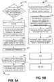
- Figure 5A is a flowchart illustrating a method for setting a configuration based on a user profile at 210 wherein the configuration is for adjusting a see-through, near-eye, mixed reality display device for alignment with an inter-pupillary distance (IPD) of one or more users, and thereafter operating the device at 214.
- IPD inter-pupillary distance
- step 542 an initial determination is made as to whether the display is aligned with a user IPD as defined in the user profile.
- one or more processors of the control circuitry 136 e.g.
- the processing unit 6, 5, the hub computing system 12 or a combination of these automatically determines whether a see-through, near-eye, mixed reality display device is aligned with an IPD of a user in accordance with an alignment criteria. If it is determined the see-through, near-eye, mixed reality display device is in alignment with a user IPD, the method moves to step 546 and monitors for changes in the alignment.
- step 544 an IPD is selected from a user profile for the identified user.
- a display device 2 ( Figure 7A , 7B ) has a display optical system for each eye, and in some embodiments, the one or more processors store the IPD as the distance between the optical axes of the display optical systems at positions which satisfy the alignment criteria. In some embodiments, the one or more processors store the position of each optical axis in the IPD data set in a user profile.
- the IPD for a user may be asymmetrical, for example with respect to the user's nose. For instance, the left eye is a little closer to the nose than the right eye is.
- adjustment values of a display adjustment mechanism for each display optical system from an initial position may be saved in the IPD data set in a user profile.
- the initial position of the display adjustment mechanism may have a fixed position with respect to a stationary frame portion, for example a point on the bridge 104. Based on this fixed position with respect to the stationary frame portion, and the adjustment values for one or more directions of movement, a position of each optical axis with respect to the stationary frame portion may be stored as a pupil alignment position for each display optical system. Additionally, in the case of the stationary frame portion being a point on the bridge, a position vector of the respective pupil to the user's nose may be estimated for each eye based on the fixed position to the point on the bridge and the adjustment values.
- the two position vectors for each eye provide at least horizontal distance components, and can include vertical distance components as well. An inter-pupillary distance IPD in one or more directions may be derived from these distance components.
- step 545 one or more adjustment values are retrieved from the IPD data set determined for the at least one display adjustment mechanism for satisfying the alignment criteria for at least one display optical system.
- the processing unit 20 causes a display adjustment mechanism, such as mechanism 803 discussed with respect to Figures 8A - 8C , to automatically adjust a display optical system 814 for each eye for alignment with the selected IPD in step 546.
- the user may be instructed on adjustments to be made to the see through head mounted display manually.
- additional user preferences such as service preferences, login information for services, and information filters are retrieved from the user profile.
- the device is operated in accordance with user preferences.
- a change may be detected by the processing unit 20 indicating the alignment with the selected IPD no longer satisfies an alignment criteria which triggers the processor in step 550 to automatically re-adjust at least one of the display optical systems for satisfying the alignment criteria.
- the alignment criteria may be a distance of a few millimeters, e.g. 3mm.
- a gaze determination method which is continually being done for tracking the focus of the user may detect the change.
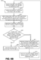
- Figure 5B is a flowchart illustrating one embodiment of a method 608 creating a user profile entry for user settings which can then automatically provide adjustable IPD alignment when operating a device 214 for one or more users of a see-through, near-eye, mixed reality display.
- the processing unit 20 automatically determines an IPD of a user based on captured data of reflected light from each eye, and in step 520, stores the IPD data associated with the user in the user profile.
- the see-though head-mounted display automatically adjusts a display optical system for each eye of the display based on the determined IPD.
- one or more adjustment values are determined relative to the IPD and the particular characteristics of the user.
- IPD data may be determined once and stored at 520.
- the method completes step 410 of storing the IPD data set and user preferences, and the method of Figure 2 completes steps 214 and 216.
- the processing unit 20 determines a distance of a point of gaze based on gaze data, and selects as the IPD either a near IPD or a far IPD based on the distance of the point of gaze.
- Figure 6A - 6C illustrate methods for aligning a see-through, near-eye, mixed reality display with an IPD.
- Figure 6A is a flowchart of a method embodiment 600 for aligning a see-through, near-eye, mixed reality display with an IPD.
- Steps 602 to 606 illustrate more details of an example of step 542 for automatically determining whether a see-through, near-eye, mixed reality display device is aligned with an IPD of a user in accordance with an alignment criteria.
- Steps 607 to 608 illustrate more detailed steps of an example for adjusting the display device for bringing the device into alignment with the user IPD as in step 548.
- the adjustment may be automatically performed by the processor or instructions electronically provided to the user for mechanical adjustment.
- the one or more processors of the see-through, near-eye, mixed reality system such as processor 210 of the control circuitry, that in processing unit 4, the mobile device 5, or the hub computing system 12, alone or in combination, identify an object in the user field of view at a distance and a direction for determining an IPD.
- the distance is at effective infinity, e.g. more than 5 feet
- the direction is straight ahead with respect to the optical axis of each display optical system.
- the distance and direction are such that when each pupil is aligned with each optical axis, the user is looking straight ahead.
- the one or more processors perform processing for drawing the user's focus to the object.
- the one or more processors electronically provide instructions requesting the user to look at the identified real object. In some instances, the user may be asked simply to look straight ahead.
- the at least one sensor such as sensor 134r or the photodetectors 152 or both in an arrangement of gaze detection elements for the respective display optical system capture data for each eye during an observation period for the object.
- the captured data may be IR image data and glints reflecting from each eye captured by an IR camera.
- the at least one sensor is an IR sensor like a position sensitive detector.
- the at least one sensor may also be the IR photodetectors.
- the at least one sensor may be a visible light camera.
- the one or more processors determine based on the captured data and the arrangement of the gaze detection elements whether each pupil is aligned with the optical axis of its respective display optical system in accordance with an alignment criteria.
- An alignment criteria may be a distance from the optical axis, e.g. 2 millimeters (mm). If so, the display device 2 has been aligned with each pupil and hence the IPD, and the one or more processors in step 609 store the position of each optical axis in the IPD data set.
- the one or more processors automatically determine one or more adjustment values for at least one display adjustment mechanism for satisfying the alignment criteria for at least one display optical system.
- “automatically determines” means the one or more processors determine the values without a user identifying the adjustment values through mechanical manipulation.
- the processor causes adjustment of the at least one respective display optical system based on the one or more adjustment values.
- the one or more processors control the at least one display adjustment mechanism 203 via the one or more display adjustment mechanism drivers 245 to move the at least one respective display optical system based on the one or more adjustment values.
- the processor electronically provides instructions to the user for applying the one or more adjustment values to the at least one display adjustment mechanism via a mechanical controller. The steps of the method embodiment may be repeated a predetermined number of times or until the alignment criteria is satisfied.
- Figure 6B is a flowchart of a method embodiment 610 for an implementation example of aligning a see-through, near-eye, mixed reality display device with an IPD of a user based on image data of a pupil for each eye in an image format.
- An image format has a predetermined size and shape, for example as may be set by an image sensor size and shape.
- An example of an image format is an image frame. The format is to provide a coordinate system, e.g. a center as an origin, for tracking a position within the image data.
- a coordinate system e.g. a center as an origin
- an IR camera, or visible light camera if desired is centered on the optical axis 142 of a display optical system 14, the image data in the image format is centered on the optical axis 142. How far off a pupil center is from the image center is a basis for determining whether the pupil is satisfactorily aligned with the optical axis.
- a real object is identified in the user field of view at a distance and a direction for determining an IPD, and in step 613, the one or more processors perform processing for drawing the user's focus to the real object.
- image data of each eye is captured in an image format during an observation period for the real object by at least one sensor aligned with an optical axis of the respective display optical system.
- a respective pupil position with respect to the respective optical axis is determined from the image data in step 615.
- a pupil area in the image data may be identified by thresholding intensity values.
- An ellipse fitting algorithm may be applied for approximating the size and shape of the pupil, and a center of a resulting ellipse may be selected as the center of the pupil.
- the center of the pupil is aligned with the optical axis of the display optical system.
- the one or more processors determine whether each pupil is aligned with the respective optical axis based on the pupil position in the image format, e.g. image frame, in accordance with an alignment criteria.
- the one or more processors determine whether the pupil position is centered in the image format, e.g. centered in the image frame, in accordance with an alignment criteria.
- the pupil position may be determined in horizontal and vertical directions for each eye with respect to the optical axis.
- the one or more processors in step 609 store the position of each optical axis in the IPD data set. If not, in step 617, the one or more processors determine at least one adjustment value for a respective display adjustment mechanism based on a mapping criteria of the at least one sensor for each display optical system not satisfying the alignment criteria. In step 618, the one or more processors control the respective display adjustment mechanism to move the respective display optical system based on the at least one adjustment value. The steps of the method embodiment may be repeated a predetermined number of times or until the alignment criteria is satisfied.
- Figure 6C is a flowchart of a method embodiment which may be used for implementing step 617 for determining at least one adjustment value.
- the one or more processors determine a horizontal pupil position difference vector.
- a pixel to distance mapping criteria may be used for each direction for which adjustment is provided. The mapping criteria may be different for vertical than for horizontal depending on the shape of the detection area of the image sensor.
- a vertical pupil position difference vector is determined as well.
- the one or more processors correlate the horizontal pupil position difference vector to a horizontal adjustment value, and in step 648, correlate the vertical pupil position difference vector to a vertical adjustment value.
- a display adjustment mechanism may have a range limit of distance to move a display optical system in any direction.
- a depth adjustment may assist with bringing an out of range adjustment value in the horizontal or vertical direction to being within range.
- Optional steps 651 and 653 may be performed.
- the one or more processors determine in optional step 651 whether any of the horizontal or vertical adjustment values are out of range. If not, alignment of the display optical system can be accomplished by movement in a two dimensional plane, and step 618 may be performed. If at least one adjustment value is out of range, the one or more processors determine in optional step 653 a depth adjustment value for bringing any out of range horizontal or vertical adjustment value closer to or within the range limit, and step 618 may be performed to adjust the display optical system.
- the display adjustment mechanism can only move the display optical system 6mm to the left
- the angle from the pupil when looking straight ahead to the position of the optical axis decreases, so a depth increase in combination with the 6mm adjustment to the left brings the optical axis closer to aligning with the pupil in accordance with an alignment criteria.
- the effect of the depth change on the vertical dimension may also be taken into account so a vertical adjustment may also be necessary or the depth adjustment value modified.
- inventions of Figures 6B and 6C may also be applied for glint data from each eye when the glints have a geometrical relationship to one another, and the sensor has a surface of discrete sensors such as pixels.
- the glints for an eye generated by the illuminators form a box or other geometric shape aligned with the optical axis of the respective display optical system for the eye by the positions of the illuminators.
- the sensor is a position sensitive detector (PSD) for detecting glints
- PSD position sensitive detector
- Image data from an IR camera, or even a visible camera provides greater accuracy for pupil position determination, but the glint data approach processes less data and is therefore computationally less intensive.
- embodiments may employ implementations for aligning a see-through, near-eye, mixed reality display with an IPD based on gaze data.
- the one or more processors determine a reference gaze vector for each eye to the real object which passes through the optical axis of a respective display optical system based on an arrangement of gaze detection elements for the display optical system.
- Embodiments for gaze determination methods are discussed in App Serial no 1467 ..
- glint reflections can estimate gaze based on a few data points of the intensity values detected for the glints, rather than processing much, much larger sets of image data of eyes.
- the position of the illuminators 153 on the eyeglass frame 115 or other support structure of a near-eye display device may be fixed so that the position of glints detected by one or more sensors is fixed in the sensor detection area.
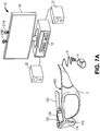
- Figure 7A is a block diagram depicting example components of one embodiment of a see-through, mixed reality display device with adjustable IPD in a system environment in which the device may operate.
- System 10 includes a see-through display device as a near-eye, head mounted display device 150 in communication with processing unit 4 via wire 6.
- head mounted display device 150 communicates with processing unit 4 via wireless communication.
- Head mounted display device 150 which in one embodiment is in the shape of eyeglasses in a frame 115, is worn on the head of a user so that the user can see through a display, embodied in this example as a display optical system 14 for each eye, and thereby have an actual direct view of the space in front of the user.
- actual direct view refers to the ability to see real world objects directly with the human eye, rather than seeing created image representations of the objects. For example, looking through glass at a room allows a user to have an actual direct view of the room, while viewing a video of a room on a television is not an actual direct view of the room.
- the system can project images of virtual objects, sometimes referred to as virtual images, on the display that are viewable by the person wearing the see-through display device while that person is also viewing real world objects through the display.
- Frame 115 provides a support for holding elements of the system in place as well as a conduit for electrical connections.
- frame 115 provides a convenient eyeglass frame as support for the elements of the system discussed further below.
- other support structures can be used.
- An example of such a structure is a visor or goggles.
- the frame 115 includes a temple or side arm for resting on each of a user's ears.
- Temple 102 is representative of an embodiment of the right temple and includes control circuitry 136 for the display device 150.
- Nose bridge 104 of the frame includes a microphone 110 for recording sounds and transmitting audio data to processing unit 4.
- processing unit 4 is worn on the user's wrist and includes much of the computing power used to operate see-through head-mounted display 150.
- Processing unit 4 may communicate wirelessly (e.g., WiFi, Bluetooth, infra-red, or other wireless communication means) to one or more hub computing systems 12.
- Hub computing system 10 may be a computer, a gaming system or console, or the like.
- the hub computing system 10 may include hardware components and/or software components such that hub computing system 10 may be used to execute applications such as gaming applications, non-gaming applications, or the like.
- hub computing system 10 may include a processor such as a standardized processor, a specialized processor, a microprocessor, or the like that may execute instructions stored on a processor readable storage device for performing the processes described herein.
- Hub computing system 10 further includes one or more capture devices, such as capture devices 21A and 21B. In other embodiments, more or less than two capture devices can be used to capture the room or other physical environment of the user.
- Capture devices 21A and 21B may be, for example, cameras that visually monitor one or more users and the surrounding space such that gestures and/or movements performed by the one or more users, as well as the structure of the surrounding space, may be captured, analyzed, and tracked to perform one or more controls or actions within an application and/or animate an avatar or on-screen character.
- An application may be executing on hub computing system 10, the display device 150, as discussed below on a mobile device 5 or a combination of these.
- Hub computing system 10 may be connected to an audiovisual device 11 such as a television, a monitor, a high-definition television (HDTV), or the like that may provide game or application visuals.
- an audiovisual device 11 such as a television, a monitor, a high-definition television (HDTV), or the like that may provide game or application visuals.
- hub computing system 10 may include a video adapter such as a graphics card and/or an audio adapter such as a sound card that may provide audiovisual signals associated with the game application, non-game application, etc.
- the audiovisual device 11 may receive the audiovisual signals from hub computing system 10 and may then output the game or application visuals and/or audio associated with the audiovisual signals.
- the audiovisual device 11 may be connected to hub computing system 10 via, for example, an S-Video cable, a coaxial cable, an HDMI cable, a DVI cable, a VGA cable, component video cable, RCA cables, etc.
- audiovisual device 11 includes internal speakers.
- audiovisual device 11, a separate stereo or hub computing system 10 is connected to external speakers 22.
- Figure 7B is a block diagram depicting example components of another embodiment of a see-through, mixed reality display device with adjustable IPD.
- the see-through head-mounted display 150 communicates with a mobile computing device 5 as an example embodiment of the processing unit 4.
- the mobile device 5 communicates via wire 6, but communication may also be wireless in other examples.
- gaming and non-gaming applications may execute on a processor of the mobile device 5 which user actions control or which user actions animate an avatar as may be displayed on a display 7 of the device 5.
- the mobile device 5 also provides a network interface for communicating with other computing devices like hub computing system 10 over the Internet or via another communication network via a wired or wireless communication medium.
- the user may participate in an online gaming session with other mobile device users and those playing on more powerful systems like hub computing system 10.
- Examples of hardware and software components of a mobile device 5 such as may be embodied in a smartphone or tablet computing device are described in Figure 20.
- Some other examples of mobile devices 5 are a laptop or notebook computer and a netbook computer.
- Figure 8A illustrates an exemplary arrangement of a see through, see-through head-mounted display embodied as eyeglasses with movable display optical systems including gaze detection elements.
- a lens for each eye represents a display optical system 14 for each eye, e.g. 14r and 14l.
- a display optical system includes a see-through lens, e.g. 116, 118 in Figures 7A , 7b , 9A-9B and 10A, 10B , as in an ordinary pair of glasses, but also contains optical elements (e.g. mirrors, filters) for seamlessly fusing virtual content with the actual direct real world view seen through the lenses 116, 118.
- optical elements e.g. mirrors, filters
- a display optical system 14 has an optical axis which is generally in the center of the see-through lens 116, 118in which light is generally collimated to provide a distortionless view.
- a goal is that the glasses sit on the user's nose at a position where each pupil is aligned with the center or optical axis of the respective lens resulting in generally collimated light reaching the user's eye for a clear or distortionless view.
- a detection area 139r, 139l of at least one sensor is aligned with the optical axis of its respective display optical system 14r, 14l so that the center of the detection area 139r, 139l is capturing light along the optical axis. If the display optical system 14 is aligned with the user's pupil, each detection area 139 of the respective sensor 134 is aligned with the user's pupil. Reflected light of the detection area 139 is transferred via one or more optical elements to the actual image sensor 134 of the camera.
- a visible light camera also commonly referred to as an RGB camera may be the sensor, and an example of an optical element or light directing element is a visible light reflecting mirror which is partially transmissive and partially reflective.
- a camera may be small, e.g. 2 millimeters (mm) by 2mm.
- the at least one sensor 134 is an IR camera or a position sensitive detector (PSD) to which the IR radiation may be directed.
- PSD position sensitive detector
- a hot reflecting surface may transmit visible light but reflect IR radiation.
- sensor 134 may be a combination of an RGB and an IR camera, and the light directing elements may include a visible light reflecting or diverting element and an IR radiation reflecting or diverting element.
- each illuminator may be an infra-red (IR) illuminator which generates a narrow beam of light at a predetermined wavelength.
- IR infra-red
- Each of the photodetectors may be selected to capture light at the predetermined wavelength. Infra-red may also include near-infrared.
- two glints and therefore two illuminators will suffice.
- other embodiments may use additional glints in determining a pupil position and hence a gaze vector.
- glint and eye data is repeatedly captured, for example at 30 frames a second or greater, data for one glint may be blocked by an eyelid or even an eyelash, but data may be gathered by a glint generated by another illuminator.
- each display optical system 14 and its arrangement of gaze detection elements facing each eye such as camera 134 and its detection area 139, optical alignment elements (not shown in this figure; see 6A-6D below), the illuminators 153 and photodetectors 152 are located on a movable inner frame portion 117l, 117r.
- a display adjustment mechanism comprises one or more motors 203 having a shaft 205 which attaches to an object for pushing and pulling the object in at least one of three dimensions.
- the object is the inner frame portion 117 which slides from left to right or vice versa within the frame 115 under the guidance and power of shafts 205 driven by motors 203.
- one motor 203 may drive both inner frames.
- a processor of control circuitry 136 of the display device 150 is able to connect to the one or more motors 203 via electrical connections within the frame 115 for controlling adjustments in different directions of the shafts 205 by the motors 203. Furthermore, the motors 203 access a power supply via the electrical connections of the frame 115 as well.
- Figure 8B illustrates another exemplary arrangement of a see through, see-through head-mounted display embodied as eyeglasses with movable display optical systems including gaze detection elements.
- the each display optical system 14 is enclosed in a separate frame portion 115l, 115r, e.g. a separate eyeglass framed section, which is movable individually by the motors 203.
- the movement range in any dimension is less than 10 millimeters. In some embodiments, the movement range is less than 6 millimeters depending on the range of frame sizes offered for a product. For the horizontal direction, moving each frame a few millimeters left or right will not impact significantly the width between the eyeglass temples, e.g. 102, which attach the display optical systems 14 to the user's head.
- Figure 8C illustrates another exemplary arrangement of a see through, see-through head-mounted display embodied as eyeglasses with movable display optical systems including gaze detection elements.
- the sensor 134r, 134l itself is in line or aligned with the optical axis at the center of its respective display optical system 14r, 14l but located on the frame 115 below the system 14.
- the camera 134 may be a depth camera or include a depth camera.
- An inter-pupillary distance may describe the distance between a user's pupils in a horizontal direction, but vertical differences may also be determined. Additionally, moving a display optical system in a depth direction between the eye and the display device 150 may also assist in aligning the optical axis with the user's pupil. A user may actually have different depths of their eyeballs within the skull. Movement of the display device in the depth direction with respect to the head may also introduce misalignment between the optical axis of the display optical system 14 and its respective pupil.
- the motors form an example of a XYZ mechanism for moving each display optical system 14 in three dimensions.
- the motors 203 in this example are located on the outer frame 115 and their shafts 205 are attached to the top and bottom of the respective inner frame portion 117.
- the operation of the motors 203 are synchronized for their shaft movements by the control circuitry 136 processor 210.
- each microdisplay assembly 173 for generating images of virtual objects or virtual images for display in the respective display optical system 14 is moved by a motor and shaft as well to maintain optical alignment with the display optical system. Examples of microdisplay assemblies 173 are described further below.
- the motors 203 are three axis motors or can move their shafts in three dimensions. For example, the shaft may be pushed and pulled in one axis of direction along a center of a cross-hair guide and move in each of two perpendicular directions in the same plane within the perpendicular openings of the cross-hair guide.
- Figure 9A is a side view of an eyeglass temple 102 of the frame 115 in an embodiment of a see-through, mixed reality display device providing support for hardware and software components.
- the physical environment facing camera 113 is a depth camera as well as a visible light sensitive camera.
- the depth camera may include an IR illuminator transmitter and a hot reflecting surface like a hot mirror in front of the visible image sensor which lets the visible light pass and directs reflected IR radiation within a wavelength range transmitted by the illuminator to a CCD or other type of depth sensor.
- the data from the sensors may be sent to a processor 210 of the control circuitry 136, or the processing unit 6, 5 or both which may process them but which the unit 6,5 may also send to a computer system over a network or hub computing system 12 for processing.
- the processing identifies objects through image segmentation and edge detection techniques and maps depth to the objects in the user's real world field of view. Additionally, the physical environment facing camera 113 may also include a light meter for measuring ambient light.
- Control circuits 136 provide various electronics that support the other components of head mounted display device 150. More details of control circuits 136 are provided below with respect to Figure 7 .
- ear phones 130 Inside, or mounted to temple 102, are ear phones 130, inertial sensors 132 GPS transceiver 144 and temperature sensor 138.
- inertial sensors 132 include a three axis magnetometer 132A, three axis gyro 132B and three axis accelerometer 132C (See Figure 7 ).
- the inertial sensors are for sensing position, orientation, and sudden accelerations of head mounted display device 150. From these movements, head position may also be determined.
- the display device 150 provides a type of display element which can generate an image of one or more virtual objects.
- a microdisplay may be used as the display element.
- a microdisplay assembly 173 in this example comprises light processing elements and a variable focus adjuster 135.
- An example of a light processing element is a microdisplay unit 120.
- Other examples include one or more optical elements such as one or more lenses of a lens system 122 and one or more reflecting elements such as surfaces 124, 124a and 124b in Figures 10A to 10D .
- Lens system 122 may comprise a single lens or a plurality of lenses.
- the microdisplay unit 120 includes an image source and generates an image of a virtual object.
- the microdisplay unit 120 is optically aligned with the lens system 122 and the reflecting surface 124 or reflecting surfaces 124a and 124b as illustrated in the following figures.
- the optical alignment may be along an optical axis 133 or an optical path 133 including one or more optical axes.
- the microdisplay unit 120 projects the image of the virtual object through lens system 122, which may direct the image light, onto reflecting element 124 which directs the light into lightguide optical element 112 as in Figures 6C and 6D or onto a partially reflecting element 124b or onto a reflecting surface 124a (e.g.
- the variable focus adjuster 135 changes the displacement between one or more light processing elements in the optical path of the microdisplay assembly or an optical power of an element in the microdisplay assembly.
- the optical power of a lens is defined as the reciprocal of its focal length, e.g. 1/focal length, so a change in one affects the other.
- the change results in a change in the region of the field of view, e.g. a region at a certain distance, which is in focus for an image generated by the microdisplay assembly 173.
- the displacement changes are guided within an armature 137 supporting at least one light processing element such as the lens system 122 and the microdisplay 120 in this example.
- the armature 137 helps stabilize the alignment along the optical path 133 during physical movement of the elements to achieve a selected displacement or optical power.
- the adjuster 135 may move one or more optical elements such as a lens in lens system 122 within the armature 137.
- the armature may have grooves or space in the area around a light processing element so it slides over the element, for example, microdisplay 120, without moving the light processing element.
- the displacement range is typically on the order of a few millimeters (mm). In one example, the range is 1-2 mm. In other examples, the armature 137 may provide support to the lens system 122 for focal adjustment techniques involving adjustment of other physical parameters than displacement.
- the adjuster 135 may be an actuator such as a piezoelectric motor.
- Other technologies for the actuator may also be used and some examples of such technologies are a voice coil formed of a coil and a permanent magnet, a magnetostriction element, and an electrostriction element.
- microdisplay 120 can be implemented using a transmissive projection technology where the light source is modulated by optically active material, backlit with white light. These technologies are usually implemented using LCD type displays with powerful backlights and high optical energy densities.
- Microdisplay 120 can also be implemented using a reflective technology for which external light is reflected and modulated by an optically active material. The illumination is forward lit by either a white source or RGB source, depending on the technology.
- Digital light processing (DLP), liquid crystal on silicon (LCOS) and Mirasol® display technology from Qualcomm, Inc. are all examples of reflective technologies which are efficient as most energy is reflected away from the modulated structure and may be used in the system described herein.
- microdisplay 120 can be implemented using an emissive technology where light is generated by the display.
- a PicoPTM engine from Microvision, Inc. emits a laser signal with a micro mirror steering either onto a tiny screen that acts as a transmissive element or beamed directly into the eye (e.g., laser).
- the configuration of the light processing elements of the microdisplay assembly 173 create a focal distance or focal region in which a virtual object appears in an image. Changing the configuration changes the focal region for the virtual object image.
- the symbol f represents the focal length of a lens such as lens system 122 in the microdisplay assembly 173.
- the lens system 122 has a front nodal point and a rear nodal point. If light rays are directed toward either nodal point at a given angle relative to the optical axis, the light rays will emerge from the other nodal point at an equivalent angle relative to the optical axis.
- the rear nodal point of lens system 122 would be between itself and the microdisplay 120.
- the distance from the rear nodal point to the microdisplay 120 may be denoted as S2.
- the front nodal point is typically within a few mm of lens system 122.
- the target location is the location of the virtual object image to be generated by the microdisplay 120 in a three-dimensional physical space.
- the distance from the front nodal point to the target location of the virtual image may be denoted as S1. Since the image is to be a virtual image appearing on the same side of the lens as the microdisplay 120, sign conventions give that S1 has a negative value.
- S1 and S2 are varied to focus virtual objects at different depths.
- an initial position may have S1 set to infinity, and S2 equal to the focal length of lens system 122.
- S1 is now about -300mm
- f is 10mm
- S2 is set currently at the initial position of the focal length, 10mm, meaning the rear nodal point of lens system 122 is 10 mm from the microdisplay 120.
- the processing unit 4 can calculate the displacement values for S1 and S2, leaving the focal length f fixed and cause the control circuitry 136 to cause a variable adjuster driver 237 (see Figure 6 ) to send drive signals to have the variable virtual focus adjuster 135 move the lens system 122 along the optical path 133 for example.
- the microdisplay unit 120 may be moved instead or in addition to moving the lens system 122.
- the focal length of at least one lens in the lens system 122 may be changed instead or with changes in the displacement along the optical path 133 as well.
- Figure 9B is a side view of an eyeglass temple in another embodiment of a mixed reality display device providing support for hardware and software components and three dimensional adjustment of a microdisplay assembly.
- the optical elements represented by reflecting surface 124 and the other elements of the microdisplay assembly 173, e.g. 120, 122 may also be moved for maintaining the optical path 133 of the light of a virtual image to the display optical system.
- An XYZ mechanism in this example made up of one or more motors represented by motor block 203 and shafts 205 under control of the processor 210 of control circuitry 136 control movement of the elements of the microdisplay assembly 173.
- An example of motors which may be used are piezoelectric motors. In the illustrated example, one motor is attached to the armature 137 and moves the variable focus adjuster 135 as well, and another representative motor 203 controls the movement of the reflecting element 124.
- Figure 10A is a top view of an embodiment of a movable display optical system 14 of a see-through, near-eye, mixed reality device 2 including an arrangement of gaze detection elements.
- a portion of the frame 115 of the see-through head-mounted display 150 will surround a display optical system 14 and provides support for elements of an embodiment of a microdisplay assembly 173 including microdisplay 120 and its accompanying elements as illustrated.
- a top portion of the frame 115 surrounding the display optical system is not depicted.
- the microphone 110 in bridge 104 is not shown in this view to focus attention on the operation of the display adjustment mechanism 203.
- the display optical system 14 in this embodiment is moved by moving an inner frame 117r, which in this example surrounds the microdisplay assembly 173 as well.
- the display adjustment mechanism is embodied in this embodiment as three axis motors 203 which attach their shafts 205 to inner frame 117r to translate the display optical system 14, which in this embodiment includes the microdisplay assembly 173, in any of three dimensions as denoted by symbol 144 indicating three (3) axes of movement.
- the display optical system 14 in this embodiment has an optical axis 142 and includes a see-through lens 118 allowing the user an actual direct view of the real world.
- the see-through lens 118 is a standard lens used in eye glasses and can be made to any prescription (including no prescription).
- see-through lens 118 can be replaced by a variable prescription lens.
- see-through, see-through head-mounted display 150 will include additional lenses.
- the display optical system 14 further comprises representative partially reflecting surface 124b.
- light from the microdisplay 120 is directed along optical path 133 via a partially reflective element 124b embedded in lens 118 which combines the virtual image view traveling along optical path 133 with the natural or actual direct view along the optical axis 142 so that the combined views are directed into a user's eye at the optical axis, the position with the most collimated light for a clearest view.
- a detection area 139r of a light sensor is also part of the display optical system 14r.
- An optical element 125 embodies the detection area 139r by capturing reflected light from the user's eye received along the optical axis 142 and directs the captured light to the sensor 134r, in this example positioned in the lens 118 within the inner frame 117r.
- sensor 134 r is a visible light camera or a combination of RGB/IR camera
- the optical element 125 includes an optical element which reflects visible light reflected from the user's eye, for example a partially reflective mirror.
- the senor 134r is an IR sensitive device such as an IR camera, and the element 125 includes a hot reflecting surface which lets visible light pass through it and reflects IR radiation to the sensor 134r.
- IR sensor is a position sensitive device (PSD).
- the depiction of the reflecting elements 125, 124, 124a and 124b in Figures 10A-10D are representative of their functions.
- the surfaces may take any number of forms and be implemented with one or more optical components in one or more arrangements for directing light to its intended destination such as a camera sensor or a user's eye.
- the arrangement allows the detection area 139 of the sensor to have its center aligned with the center of the display optical system 14.
- the image sensor 134r captures the detection area 139, so an image captured at the image sensor is centered on the optical axis because the detection area 139 is.
- the display optical system 14r is aligned with the pupil.
- the distance between the optical centers matches or is aligned with the user's inter-pupillary distance.
- the inter-pupillary distance can be aligned with the display optical systems 14 in three dimensions.
- one or more processors in the processing unit 20 or the control circuitry 136 or both use a mapping value which correlates a distance or length measurement unit to a pixel or other discrete unit or area of the image for determining how far off the image of the pupil is from the optical axis 142. Based on the distance determined, the one or more processors determine adjustments of how much distance and in which direction the display optical system 14r is to be moved to align the optical axis 142 with the pupil. Control signals are applied by one or more display adjustment mechanism drivers 245 to each of the components, e.g. motors 203, making up one or more display adjustment mechanisms 203.
- the motors move their shafts 205 to move the inner frame 117r in at least one direction indicated by the control signals.
- On the temple side of the inner frame 117r are flexible sections of the frame 115 which are attached to the inner frame 117r at one end and slide within grooves 217a and 217b within the interior of the temple frame 115 to anchor the inner frame 117 to the frame 115 as the display optical system 14 is move in any of three directions for width, height or depth changes with respect to the respective pupil.
- the display optical system 14 includes other gaze detection elements.
- attached to frame 117r on the sides of lens 118 are at least 2 but may be more, infra-red (IR) illuminating devices 153 which direct narrow infra-red light beams within a particular wavelength range at the user's eye to each generate a respective glint on a surface of the user's cornea.
- the illuminators and any photodiodes may be on the lenses, for example at the corners or edges.
- in addition to the at least 2 infra-red (IR) illuminating devices 153 are IR photodetectors 152.
- Each photodetector 152 is sensitive to IR radiation within the particular wavelength range of its corresponding IR illuminator 153 across the lens 118 and is positioned to detect a respective glint. As shown in Figures 6A-4C , the illuminator and photodetector are separated by a barrier 154 so that incident IR light from the illuminator 153 does not interfere with reflected IR light being received at the photodetector 152. In the case where the sensor is an IR sensor, the photodetectors 152 may not be needed or may be an additional capture source. With a visible light camera, the photodetectors 152 capture light from glints and generate glint intensity values.
- sensor 134r may be an IR camera which captures not only glints, but also an infra-red or near-infra-red image of the user's eye including the pupil.
- the sensor device 134r is a position sensitive device (PSD), sometimes referred to as an optical position sensor.
- PSD position sensitive device
- the position of detected light on the surface of the sensor is identified.
- a PSD can be selected which is sensitive to a wavelength range of IR illuminators for the glints.
- an electrical signal is generated which identifies the location on the surface of the detector.
- the surface of a PSD is divided into discrete sensors like pixels from which the location of the light can be determined.
- a PSD isotropic sensor may be used in which a change in local resistance on the surface can be used to identify the location of the light spot on the PSD.
- Other embodiments of PSDs may also be used.
- the positions of the gaze detection elements e.g. the detection area 139 and the illuminators 153 and photodetectors 152 are fixed with respect to the optical axis of the display optical system 14. These elements may move with the display optical system 14r, and hence its optical axis, on the inner frame, but their spatial relationship to the optical axis 142 does not change.
- Figure 10B is a top view of another embodiment of a movable display optical system of a see-through, near-eye, mixed reality device including an arrangement of gaze detection elements.
- light sensor 134r may be embodied as a visible light camera, sometimes referred to as an RGB camera, or it may be embodied as an IR camera or a camera capable of processing light in both the visible and IR ranges, e.g. a depth camera.
- the image sensor 134r is the detection area 139r.
- the image sensor 134 of the camera is located vertically on the optical axis 142 of the display optical system.
- the camera may be located on frame 115 either above or below see-through lens 118 or embedded in the lens 118.
- the illuminators 153 provide light for the camera, and in other embodiments the camera captures images with ambient lighting.
- Image data captured may be used to determine alignment of the pupil with the optical axis. Gaze determination techniques based on image data, glint data or both may be used based on the geometry of the gaze detection elements.
- the motor 203 in bridge 104 moves the display optical system 14r in a horizontal direction with respect to the user's eye as indicated by directional symbol 144.
- the flexible frame portions 215a and 215b slide within grooves 217a and 217b as the system 14 is moved.
- reflecting element 124a of an microdisplay assembly 173 embodiment is stationery. As the IPD is typically determined once and stored, any adjustment of the focal length between the microdisplay 120 and the reflecting element 124a that may be done may be accomplished by the microdisplay assembly, for example via adjustment of the microdisplay elements within the armature 137.
- Figure 10C is a top view of a third embodiment of a movable display optical system of a see-through, near-eye, mixed reality device including an arrangement of gaze detection elements.
- the display optical system 14 has a similar arrangement of gaze detection elements including IR illuminators 153 and photodetectors 152, and a light sensor 134r located on the frame 115 or lens 118 below or above optical axis 142.
- the display optical system 14 includes a light guide optical element 112 as the reflective element for directing the virtual images into the user's eye and is situated between an additional see-through lens 116 and see-through lens 118.
- a microdisplay assembly 173 is attached on the temple 102 in this example to a display adjustment mechanism 203 for the display optical system 14 embodied as a set of three axis motor 203 with shafts 205 include at least one for moving the microdisplay assembly.
- a display adjustment mechanism 203 on the bridge 104 are representative of the other components of the display adjustment mechanism 203 which provides three axes of movement 144. In another embodiment, the motors may operate to only move the devices via their attached shafts 205 in the horizontal direction.
- the motor 203 for the microdisplay assembly 173 would also move it horizontally for maintaining alignment between the light coming out of the microdisplay 120 and the reflecting element 124.
- a processor 210 of the control circuitry (see Figure 7 ) coordinates their movement.
- Lightguide optical element 112 transmits light from microdisplay 120 to the eye of the user wearing head mounted display device 150. Lightguide optical element 112 also allows light from in front of the head mounted display device 150 to be transmitted through lightguide optical element 112 to the user's eye thereby allowing the user to have an actual direct view of the space in front of head mounted display device 150 in addition to receiving a virtual image from microdisplay 120. Thus, the walls of lightguide optical element 112 are see-through.
- Lightguide optical element 112 includes a first reflecting surface 124 (e.g., a mirror or other surface). Light from microdisplay 120 passes through lens 122 and becomes incident on reflecting surface 124. The reflecting surface 124 reflects the incident light from the microdisplay 120 such that light is trapped inside a planar, substrate comprising lightguide optical element 112 by internal reflection.
- the trapped light waves After several reflections off the surfaces of the substrate, the trapped light waves reach an array of selectively reflecting surfaces 126. Note that only one of the five surfaces is labeled 126 to prevent over-crowding of the drawing. Reflecting surfaces 126 couple the light waves incident upon those reflecting surfaces out of the substrate into the eye of the user. As different light rays will travel and bounce off the inside of the substrate at different angles, the different rays will hit the various reflecting surface 126 at different angles. Therefore, different light rays will be reflected out of the substrate by different ones of the reflecting surfaces. The selection of which light rays will be reflected out of the substrate by which surface 126 is engineered by selecting an appropriate angle of the surfaces 126.
- each eye will have its own lightguide optical element 112.
- each eye can have its own microdisplay 120 that can display the same image in both eyes or different images in the two eyes.
- Figure 10D is a top view of a fourth embodiment of a movable display optical system of a see-through, near-eye, mixed reality device including an arrangement of gaze detection elements.
- This embodiment is similar to Figure 6C 's embodiment including a light guide optical element 112.
- the only light detectors are the IR photodetectors 152, so this embodiment relies on glint detection only for gaze detection as discussed in the examples below.
- a full near-eye, mixed reality display device would include as examples another set of lenses 116 and/or 118, another lightguide optical element 112 for the embodiments of Figures 6C and 6D , another micro display 120, another lens system 122, likely another room facing camera 113, another eye tracking camera 134 for the embodiments of Figures 6A to 6D , earphones 130, and a temperature sensor 138.
- Figure 11 is a block diagram of one embodiment of hardware and software components of a see-through, near-eye display unit 2 as may be used with one or more embodiments.
- Figure 12 is a block diagram describing the various components of a processing unit 20.
- see-through head-mounted display 150 receive instructions about a virtual image from processing unit 20 and provides the sensor information back to processing unit 20.
- Software and hardware components which may be embodied in a processing unit 20, will receive the sensory information from the display device 150 and may also receive sensory information from hub computing device 12 (). Based on that information, processing unit 20 will determine where and when to provide a virtual image to the user and send instructions accordingly to the control circuitry 136 of the display device 150.
- Control circuit 200 includes processor 210, memory controller 212 in communication with memory 214 (e.g., D-RAM), camera interface 216, camera buffer 218, display driver 220, display formatter 222, timing generator 226, display out interface 228, and display in interface 230.
- memory 214 e.g., D-RAM
- camera interface 216 e.g., camera buffer 218, display driver 220, display formatter 222, timing generator 226, display out interface 228, and display in interface 230.
- all of components of control circuit 220 are in communication with each other via dedicated lines of one or more buses.
- each of the components of control circuit 200 are in communication with processor 210.
- Camera interface 216 provides an interface to the two physical environment facing cameras 113 and each eye camera 134 and stores respective images received from the cameras 113, 134 in camera buffer 218.
- Display driver 220 will drive microdisplay 120.
- Display formatter 222 may provide information, about the virtual image being displayed on microdisplay 120 to one or more processors of one or more computer systems, e.g. 20, 12, 210 performing processing for the augmented reality system.
- Timing generator 226 is used to provide timing data for the system.
- Display out 228 is a buffer for providing images from physical environment facing cameras 113 and the eye cameras 134 to the processing unit 4.
- Display in 230 is a buffer for receiving images such as a virtual image to be displayed on microdisplay 120.
- Display out 228 and display in 230 communicate with band interface 232 which is an interface to processing unit 4.
- Power management circuit 202 includes voltage regulator 234, eye tracking illumination driver 236, variable adjuster driver 237, photodetector interface 239, audio DAC and amplifier 238, microphone preamplifier and audio ADC 240, temperature sensor interface 242, display adjustment mechanism driver(s) 245 and clock generator 244.
- Voltage regulator 234 receives power from processing unit 4 via band interface 232 and provides that power to the other components of head mounted display device 150.
- Illumination driver 236 provides the IR lightsource for illumination devices 153, as described above.
- Audio DAC and amplifier 238 receives the audio information from earphones 130.
- Microphone preamplifier and audio ADC 240 provides an interface for microphone 110.
- Temperature sensor interface 242 is an interface for temperature sensor 138.
- One or more display adjustment drivers 245 provide control signals to one or more motors or other devices making up each display adjustment mechanism 203 indicating which represent adjustment amounts of movement in at least one of three directions.
- Power management unit 202 also provides power and receives data back from three axis magnetometer 132A, three axis gyro 132B and three axis accelerometer 132C.
- the variable adjuster driver 237 provides a control signal, for example a drive current or a drive voltage, to the adjuster 135 to move one or more elements of the microdisplay assembly 173 to achieve a displacement for a focal region calculated by software executing in the processing unit 4 or the hub computer 12 or both.
- a control signal for example a drive current or a drive voltage
- the variable adjuster driver 237 receives timing signals from the timing generator 226, or alternatively, the clock generator 244 to operate at a programmed rate or frequency.
- the photodetector interface 239 receives performs any analog to digital conversion needed for voltage or current readings from each photodetector, stores the readings in a processor readable format in memory via the memory controller 212, and monitors the operation parameters of the photodetectors 152 such as temperature and wavelength accuracy.
- Figure 12 is a block diagram of one embodiment of the hardware and software components of a processing unit 4 associated with a see-through, near-eye display unit.
- the mobile device 5 may include this embodiment of hardware and software components as well or similar components which perform similar functions.
- Figure 8 shows controls circuit 304 in communication with power management circuit 306.
- Control circuit 304 includes a central processing unit (CPU) 320, graphics processing unit (GPU) 322, cache 324, RAM 326, memory control 328 in communication with memory 330 (e.g., D-RAM), flash memory controller 332 in communication with flash memory 334 (or other type of non-volatile storage), display out buffer 336 in communication with see-through, see-through head-mounted display 150 via band interface 302 and band interface 232, display in buffer 338 in communication with see-through head-mounted display 150 via band interface 302 and band interface 232, microphone interface 340 in communication with an external microphone connector 342 for connecting to a microphone, PCI express interface for connecting to a wireless communication device 346, and USB port(s) 348.
- CPU central processing unit
- GPU graphics processing unit
- RAM random access memory
- memory control 328 in communication with memory 330 (e.g., D-RAM)
- flash memory controller 332 in communication with flash memory 334 (or other type of non-volatile storage)
- display out buffer 336 in
- wireless communication component 346 can include a Wi-Fi enabled communication device, Bluetooth communication device, infrared communication device, etc.
- the USB port can be used to dock the processing unit 4 to hub computing device 12 in order to load data or software onto processing unit 20 as well as charge processing unit 4.
- CPU 320 and GPU 322 are the main workhorses for determining where, when and how to insert images into the view of the user.
- Power management circuit 306 includes clock generator 360, analog to digital converter 362, battery charger 364, voltage regulator 366, see-through, near-eye display power source 376, and temperature sensor interface 372 in communication with temperature sensor 374 (located on the wrist band of processing unit 4).
- An alternating current to direct current converter 362 is connected to a charging jack 370 for receiving an AC supply and creating a DC supply for the system.
- Voltage regulator 366 is in communication with battery 368 for supplying power to the system.
- Battery charger 364 is used to charge battery 368 (via voltage regulator 366) upon receiving power from charging jack 370.
- Device power interface 376 provides power to the display device 150.
- the figures above provide examples of geometries of elements for a display optical system which provide a basis for different methods of determining an IPD as discussed in the following figures.
- the method embodiments may refer to elements of the systems and structures above for illustrative context; however, the method embodiments may operate in system or structural embodiments other than those described above.
- FIG 16 is a block diagram of an exemplary mobile device which may operate in embodiments of the technology. Exemplary electronic circuitry of a typical mobile phone is depicted.
- the phone 900 includes one or more microprocessors 912, and memory 1010 (e.g., non-volatile memory such as ROM and volatile memory such as RAM) which stores processor-readable code which is executed by one or more processors of the control processor 912 to implement the functionality described herein.
- memory 1010 e.g., non-volatile memory such as ROM and volatile memory such as RAM
- Mobile device 900 may include, for example, processors 912, memory 1010 including applications and non-volatile storage.
- the processor 912 can implement communications, as well as any number of applications, including the interaction applications discussed herein.
- Memory 1010 can be any variety of memory storage media types, including non-volatile and volatile memory.
- a device operating system handles the different operations of the mobile device 900 and may contain user interfaces for operations, such as placing and receiving phone calls, text messaging, checking voicemail, and the like.
- the applications 1030 can be any assortment of programs, such as a camera application for photos and/or videos, an address book, a calendar application, a media player, an internet browser, games, other multimedia applications, an alarm application, other third party applications, the interaction application discussed herein, and the like.
- the non-volatile storage component 1040 in memory 1010 contains data such as web caches, music, photos, contact data, scheduling data, and other files.
- the processor 912 also communicates with RF transmit/receive circuitry 906 which in turn is coupled to an antenna 902, with an infrared transmitted/receiver 908, with any additional communication channels 1060 like Wi-Fi or Bluetooth, and with a movement/orientation sensor 914 such as an accelerometer.
- Accelerometers have been incorporated into mobile devices to enable such applications as intelligent user interfaces that let users input commands through gestures, indoor GPS functionality which calculates the movement and direction of the device after contact is broken with a GPS satellite, and to detect the orientation of the device and automatically change the display from portrait to landscape when the phone is rotated.
- An accelerometer can be provided, e.g., by a micro-electromechanical system (MEMS) which is a tiny mechanical device (of micrometer dimensions) built onto a semiconductor chip. Acceleration direction, as well as orientation, vibration and shock can be sensed.
- the processor 912 further communicates with a ringer/vibrator 916, a user interface keypad/screen, biometric sensor system 918, a speaker 1020, a microphone 922, a camera 924, a light sensor 926 and a temperature sensor 928.
- MEMS micro-electromechanical system
- the processor 912 controls transmission and reception of wireless signals.
- the processor 912 provides a voice signal from microphone 922, or other data signal, to the RF transmit/receive circuitry 906.
- the transmit/receive circuitry 906 transmits the signal to a remote station (e.g., a fixed station, operator, other cellular phones, etc.) for communication through the antenna 902.
- the ringer/vibrator 916 is used to signal an incoming call, text message, calendar reminder, alarm clock reminder, or other notification to the user.
- the transmit/receive circuitry 906 receives a voice or other data signal from a remote station through the antenna 902. A received voice signal is provided to the speaker 1020 while other received data signals are also processed appropriately.
- a physical connector 988 can be used to connect the mobile device 900 to an external power source, such as an AC adapter or powered docking station.
- the physical connector 988 can also be used as a data connection to a computing device. The data connection allows for operations such as synchronizing mobile device data with the computing data on another device.
- a GPS receiver 965 utilizing satellite-based radio navigation to relay the position of the user applications is enabled for such service.
- Computer readable storage media are also processor readable storage media. Such media may include volatile and nonvolatile, removable and non-removable media implemented in any method or technology for storage of information such as computer readable instructions, data structures, program modules or other data.
- Computer storage media includes, but is not limited to, RAM, ROM, EEPROM, cache, flash memory or other memory technology, CD-ROM, digital versatile disks (DVD) or other optical disk storage, memory sticks or cards, magnetic cassettes, magnetic tape, a media drive, a hard disk, magnetic disk storage or other magnetic storage devices, or any other medium which can be used to store the desired information and which can accessed by a computer.
- Figure 13 illustrates an example of a suitable computing system environment 700 such as personal computer.
- an exemplary system for implementing the technology includes a general purpose computing device in the form of a computer 710.
- Components of computer 710 may include, but are not limited to, a processing unit 720, a system memory 730, and a system bus 721 that couples various system components including the system memory to the processing unit 720.
- the system bus 721 may be any of several types of bus structures including a memory bus or memory controller, a peripheral bus, and a local bus using any of a variety of bus architectures.
- such architectures include Industry Standard Architecture (ISA) bus, Micro Channel Architecture (MCA) bus, Enhanced ISA (EISA) bus, Video Electronics Standards Association (VESA) local bus, and Peripheral Component Interconnect (PCI) bus also known as Mezzanine bus.
- ISA Industry Standard Architecture
- MCA Micro Channel Architecture
- EISA Enhanced ISA
- VESA Video Electronics Standards Association
- PCI Peripheral Component Interconnect
- Computer 710 typically includes a variety of computer readable media.
- Computer readable media can be any available media that can be accessed by computer 710 and includes both volatile and nonvolatile media, removable and non-removable media.
- Computer readable media may comprise computer storage media and communication media.
- Computer storage media includes both volatile and nonvolatile, removable and non-removable media implemented in any method or technology for storage of information such as computer readable instructions, data structures, program modules or other data.
- Computer storage media includes, but is not limited to, RAM, ROM, EEPROM, flash memory or other memory technology, CD-ROM, digital versatile disks (DVD) or other optical disk storage, magnetic cassettes, magnetic tape, magnetic disk storage or other magnetic storage devices, or any other medium which can be used to store the desired information and which can accessed by computer 710.
- Communication media typically embodies computer readable instructions, data structures, program modules or other data in a modulated data signal such as a carrier wave or other transport mechanism and includes any information delivery media.
- modulated data signal means a signal that has one or more of its characteristics set or changed in such a manner as to encode information in the signal.
- communication media includes wired media such as a wired network or direct-wired connection, and wireless media such as acoustic, RF, infrared and other wireless media. Combinations of the any of the above should also be included within the scope of computer readable media.
- the system memory 730 includes computer storage media in the form of volatile and/or nonvolatile memory such as read only memory (ROM) 731 and random access memory (RAM) 732.
- ROM read only memory
- RAM random access memory
- BIOS basic input/output system 733
- RAM 732 typically contains data and/or program modules that are immediately accessible to and/or presently being operated on by processing unit 720.
- Figure 7 illustrates operating system 734, application programs 735, other program modules 736, and program data 737.
- the computer 710 may also include other removable/non-removable, volatile/nonvolatile computer storage media.
- Figure 13 illustrates a hard disk drive 740 that reads from or writes to non-removable, nonvolatile magnetic media, a magnetic disk drive 751 that reads from or writes to a removable, nonvolatile magnetic disk 752, and an optical disk drive 755 that reads from or writes to a removable, nonvolatile optical disk 756 such as a CD ROM or other optical media.
- removable/non-removable, volatile/nonvolatile computer storage media that can be used in the exemplary operating environment include, but are not limited to, magnetic tape cassettes, flash memory cards, digital versatile disks, digital video tape, solid state RAM, solid state ROM, and the like.
- the hard disk drive 741 is typically connected to the system bus 721 through an non-removable memory interface such as interface 740, and magnetic disk drive 751 and optical disk drive 755 are typically connected to the system bus 721 by a removable memory interface, such as interface 750.
- hard disk drive 741 is illustrated as storing operating system 744, application programs 745, other program modules 746, and program data 747. Note that these components can either be the same as or different from operating system 734, application programs 735, other program modules 736, and program data 737. Operating system 744, application programs 745, other program modules 746, and program data 747 are given different numbers here to illustrate that, at a minimum, they are different copies.
- a user may enter commands and information into the computer 20 through input devices such as a keyboard 762 and pointing device 761, commonly referred to as a mouse, trackball or touch pad.
- Other input devices may include a microphone, joystick, game pad, satellite dish, scanner, or the like.
- These and other input devices are often connected to the processing unit 720 through a user input interface 760 that is coupled to the system bus, but may be connected by other interface and bus structures, such as a parallel port, game port or a universal serial bus (USB).
- a monitor 791 or other type of display device is also connected to the system bus 721 via an interface, such as a video interface 790.
- computers may also include other peripheral output devices such as speakers 797 and printer 796, which may be connected through a output peripheral interface 790.
- the computer 710 may operate in a networked environment using logical connections to one or more remote computers, such as a remote computer 780.
- the remote computer 780 may be a personal computer, a server, a router, a network PC, a peer device or other common network node, and typically includes many or all of the elements described above relative to the computer 710, although only a memory storage device 781 has been illustrated in Figure 7 .
- the logical connections depicted in Figure 7 include a local area network (LAN) 771 and a wide area network (WAN) 773, but may also include other networks.
- LAN local area network
- WAN wide area network
- Such networking environments are commonplace in offices, enterprise-wide computer networks, intranets and the Internet.
- the computer 710 When used in a LAN networking environment, the computer 710 is connected to the LAN 771 through a network interface or adapter 770. When used in a WAN networking environment, the computer 710 typically includes a modem 772 or other means for establishing communications over the WAN 773, such as the Internet.
- the modem 772 which may be internal or external, may be connected to the system bus 721 via the user input interface 760, or other appropriate mechanism.
- program modules depicted relative to the computer 710, or portions thereof may be stored in the remote memory storage device.
- Figure 13 illustrates remote application programs 785 as residing on memory device 781. It will be appreciated that the network connections shown are exemplary and other means of establishing a communications link between the computers may be used.
- the computing system environment 700 is only one example of a suitable computing environment and is not intended to suggest any limitation as to the scope of use or functionality of the technology. Neither should the computing environment 700 be interpreted as having any dependency or requirement relating to any one or combination of components illustrated in the exemplary operating environment 700.
- the technology is operational with numerous other general purpose or special purpose computing system environments or configurations.
- Examples of well-known computing systems, environments, and/or configurations that may be suitable for use with the technology include, but are not limited to, personal computers, server computers, hand-held or laptop devices, multiprocessor systems, microprocessor-based systems, set top boxes, programmable consumer electronics, network PCs, minicomputers, mainframe computers, distributed computing environments that include any of the above systems or devices, and the like.
- program modules include routines, programs, objects, components, data structures, etc. that perform particular tasks or implement particular abstract data types.
- the technology may also be practiced in distributed computing environments where tasks are performed by remote processing devices that are linked through a communications network.
- program modules may be located in both local and remote computer storage media including memory storage devices.
Applications Claiming Priority (2)
| Application Number | Priority Date | Filing Date | Title |
|---|---|---|---|
| US201113221669A | 2011-08-30 | 2011-08-30 | |
| PCT/US2012/052839 WO2013033195A2 (en) | 2011-08-30 | 2012-08-29 | Head mounted display with iris scan profiling |
Publications (3)
| Publication Number | Publication Date |
|---|---|
| EP2751609A2 EP2751609A2 (en) | 2014-07-09 |
| EP2751609A4 EP2751609A4 (en) | 2015-02-18 |
| EP2751609B1 true EP2751609B1 (en) | 2017-08-16 |
Family
ID=47757153
Family Applications (1)
| Application Number | Title | Priority Date | Filing Date |
|---|---|---|---|
| EP12827964.3A Active EP2751609B1 (en) | 2011-08-30 | 2012-08-29 | Head mounted display with iris scan profiling |
Country Status (6)
| Country | Link |
|---|---|
| US (1) | US9202443B2 (zh) |
| EP (1) | EP2751609B1 (zh) |
| JP (1) | JP6144681B2 (zh) |
| KR (1) | KR20140059213A (zh) |
| CN (1) | CN103033936A (zh) |
| WO (1) | WO2013033195A2 (zh) |
Families Citing this family (130)
| Publication number | Priority date | Publication date | Assignee | Title |
|---|---|---|---|---|
| US9132352B1 (en) | 2010-06-24 | 2015-09-15 | Gregory S. Rabin | Interactive system and method for rendering an object |
| US9563265B2 (en) * | 2012-01-12 | 2017-02-07 | Qualcomm Incorporated | Augmented reality with sound and geometric analysis |
| US9710483B1 (en) * | 2012-03-16 | 2017-07-18 | Miller Nelson LLC | Location-conscious social networking apparatuses, methods and systems |
| US8798332B2 (en) * | 2012-05-15 | 2014-08-05 | Google Inc. | Contact lenses |
| US9600068B2 (en) * | 2013-03-13 | 2017-03-21 | Sony Interactive Entertainment Inc. | Digital inter-pupillary distance adjustment |
| CN107656618B (zh) * | 2013-03-15 | 2021-03-23 | 奇跃公司 | 显示系统和方法 |
| US20140362110A1 (en) * | 2013-06-08 | 2014-12-11 | Sony Computer Entertainment Inc. | Systems and methods for customizing optical representation of views provided by a head mounted display based on optical prescription of a user |
| US10345903B2 (en) * | 2013-07-30 | 2019-07-09 | Microsoft Technology Licensing, Llc | Feedback for optic positioning in display devices |
| CN103440036B (zh) * | 2013-08-23 | 2018-04-17 | Tcl集团股份有限公司 | 三维图像的显示和交互操作方法及装置 |
| US10310597B2 (en) | 2013-09-03 | 2019-06-04 | Tobii Ab | Portable eye tracking device |
| US10321055B2 (en) * | 2013-09-03 | 2019-06-11 | Seeing Machines Limited | Low power eye tracking system and method |
| US10686972B2 (en) | 2013-09-03 | 2020-06-16 | Tobii Ab | Gaze assisted field of view control |
| KR101882594B1 (ko) | 2013-09-03 | 2018-07-26 | 토비 에이비 | 휴대용 눈 추적 디바이스 |
| US9630105B2 (en) | 2013-09-30 | 2017-04-25 | Sony Interactive Entertainment Inc. | Camera based safety mechanisms for users of head mounted displays |
| CN103785169A (zh) * | 2013-12-18 | 2014-05-14 | 微软公司 | 混合现实的竞技场 |
| IN2013CH06147A (zh) * | 2013-12-30 | 2015-07-03 | Samsung Electronics Co Ltd | |
| KR102191151B1 (ko) | 2013-12-30 | 2020-12-16 | 삼성디스플레이 주식회사 | 전자 기기 및 전자 기기의 구동 방법 |
| CN104808775B (zh) * | 2014-01-24 | 2018-07-10 | 北京奇虎科技有限公司 | 判断头戴式智能设备鉴权信息有效性的装置和方法 |
| CN104809380B (zh) * | 2014-01-24 | 2018-10-30 | 北京奇虎科技有限公司 | 头戴式智能设备及其使用者的身份一致性的判断方法 |
| WO2015109887A1 (zh) * | 2014-01-24 | 2015-07-30 | 北京奇虎科技有限公司 | 判断头戴式智能设备的操作及鉴权信息有效性的装置和方法 |
| CN104808778B (zh) * | 2014-01-24 | 2019-03-01 | 北京奇虎科技有限公司 | 判断头戴式智能设备操作有效性的装置和方法 |
| CN104809371B (zh) * | 2014-01-24 | 2018-12-11 | 北京奇虎科技有限公司 | 判断头戴式智能设备的鉴权信息有效性的装置和方法 |
| EP3116616B1 (en) | 2014-03-14 | 2019-01-30 | Sony Interactive Entertainment Inc. | Gaming device with volumetric sensing |
| DE102014207251A1 (de) * | 2014-04-15 | 2015-10-15 | Siemens Aktiengesellschaft | Datenbrille, Datenübertragungsnetzwerk und Verfahren zum drahtlosen Datenaustausch |
| KR102173699B1 (ko) * | 2014-05-09 | 2020-11-03 | 아이플루언스, 인크. | 안구 신호들의 인식 및 지속적인 생체 인증을 위한 시스템과 방법들 |
| US9323983B2 (en) * | 2014-05-29 | 2016-04-26 | Comcast Cable Communications, Llc | Real-time image and audio replacement for visual acquisition devices |
| CN106663187B (zh) * | 2014-07-09 | 2020-11-06 | 三星电子株式会社 | 用于识别生物测定信息的方法和设备 |
| WO2016017945A1 (en) | 2014-07-29 | 2016-02-04 | Samsung Electronics Co., Ltd. | Mobile device and method of pairing the same with electronic device |
| KR102437104B1 (ko) | 2014-07-29 | 2022-08-29 | 삼성전자주식회사 | 모바일 디바이스에서 촬영된 전자 기기와 페어링하는 방법 및 장치 |
| US9965030B2 (en) * | 2014-07-31 | 2018-05-08 | Samsung Electronics Co., Ltd. | Wearable glasses and method of displaying image via the wearable glasses |
| KR102361025B1 (ko) * | 2014-07-31 | 2022-02-08 | 삼성전자주식회사 | 웨어러블 글래스 및 웨어러블 글래스를 통하여 영상을 디스플레이하는 방법 |
| US10540907B2 (en) | 2014-07-31 | 2020-01-21 | Intelligent Technologies International, Inc. | Biometric identification headpiece system for test taking |
| US9959777B2 (en) * | 2014-08-22 | 2018-05-01 | Intelligent Technologies International, Inc. | Secure testing device, system and method |
| US10410535B2 (en) | 2014-08-22 | 2019-09-10 | Intelligent Technologies International, Inc. | Secure testing device |
| JP6574939B2 (ja) * | 2014-09-16 | 2019-09-18 | ソニー株式会社 | 表示制御装置、表示制御方法、表示制御システムおよび頭部装着ディスプレイ |
| JP6701631B2 (ja) * | 2015-06-22 | 2020-05-27 | セイコーエプソン株式会社 | 表示装置、表示装置の制御方法、表示システム、及び、プログラム |
| JP6539981B2 (ja) * | 2014-10-24 | 2019-07-10 | セイコーエプソン株式会社 | 表示装置、表示装置の制御方法、表示システム、及び、プログラム |
| US10438106B2 (en) | 2014-11-04 | 2019-10-08 | Intellignet Technologies International, Inc. | Smartcard |
| US20160131902A1 (en) * | 2014-11-12 | 2016-05-12 | Anthony J. Ambrus | System for automatic eye tracking calibration of head mounted display device |
| US9886598B2 (en) * | 2014-12-29 | 2018-02-06 | Paypal, Inc. | Automatic adjustment of a display to obscure data |
| US10154239B2 (en) | 2014-12-30 | 2018-12-11 | Onpoint Medical, Inc. | Image-guided surgery with surface reconstruction and augmented reality visualization |
| CN112667069A (zh) * | 2015-03-13 | 2021-04-16 | 苹果公司 | 用于自动识别眼睛追踪设备的至少一个用户的方法以及眼睛追踪设备 |
| US10678897B2 (en) | 2015-04-16 | 2020-06-09 | Tobii Ab | Identification, authentication, and/or guiding of a user using gaze information |
| JP6722272B2 (ja) * | 2015-04-16 | 2020-07-15 | トビー エービー | 凝視情報を使用するユーザの識別および/または認証 |
| US9690119B2 (en) | 2015-05-15 | 2017-06-27 | Vertical Optics, LLC | Wearable vision redirecting devices |
| IL244255A (en) | 2016-02-23 | 2017-04-30 | Vertical Optics Llc | Wearable devices for deflecting vision |
| WO2016187462A1 (en) * | 2015-05-19 | 2016-11-24 | Magic Leap, Inc. | Dual composite light field device |
| AU2016264503B2 (en) * | 2015-05-20 | 2021-10-28 | Magic Leap, Inc. | Tilt shift iris imaging |
| US11252399B2 (en) * | 2015-05-28 | 2022-02-15 | Microsoft Technology Licensing, Llc | Determining inter-pupillary distance |
| WO2016191953A1 (zh) * | 2015-05-29 | 2016-12-08 | 深圳市柔宇科技有限公司 | 自适配显示调节的方法及头戴式显示设备 |
| US9824499B2 (en) * | 2015-06-23 | 2017-11-21 | Microsoft Technology Licensing, Llc | Mixed-reality image capture |
| EP3337383A4 (en) * | 2015-08-21 | 2019-04-03 | Magic Leap, Inc. | EYE SHAPE ESTIMATION |
| CA2996039A1 (en) | 2015-08-21 | 2017-03-02 | Magic Leap, Inc. | Eyelid shape estimation using eye pose measurement |
| JP2017049867A (ja) * | 2015-09-03 | 2017-03-09 | 日本電気株式会社 | 認証装置、防犯システム、認証方法およびプログラム |
| JP6897831B2 (ja) * | 2015-09-03 | 2021-07-07 | 日本電気株式会社 | 認証装置、防犯システム、認証装置による制御方法およびプログラム |
| US9298283B1 (en) | 2015-09-10 | 2016-03-29 | Connectivity Labs Inc. | Sedentary virtual reality method and systems |
| CN114140867A (zh) | 2015-10-16 | 2022-03-04 | 奇跃公司 | 使用眼睛特征的眼睛姿态识别 |
| JP7210280B2 (ja) | 2015-11-04 | 2023-01-23 | マジック リープ, インコーポレイテッド | ライトフィールドディスプレイの計測 |
| US9965819B1 (en) | 2015-11-25 | 2018-05-08 | John DeVries | Real-time school bus and student tracking |
| US20170185805A1 (en) * | 2015-12-28 | 2017-06-29 | Intelligent Technologies International, Inc. | Intrusion-protected memory component |
| US10678958B2 (en) | 2015-12-28 | 2020-06-09 | Intelligent Technologies International, Inc. | Intrusion-protected memory component |
| WO2017127366A1 (en) | 2016-01-19 | 2017-07-27 | Magic Leap, Inc. | Eye image collection, selection, and combination |
| US10089453B2 (en) * | 2016-03-07 | 2018-10-02 | Magic Leap, Inc. | Blue light adjustment for biometric identification |
| CN111329554B (zh) | 2016-03-12 | 2021-01-05 | P·K·朗 | 用于手术的装置与方法 |
| CN105955476A (zh) * | 2016-04-28 | 2016-09-21 | 乐视控股(北京)有限公司 | 用于电子设备的指令触发方法、装置及电子设备 |
| CN105930816A (zh) * | 2016-05-05 | 2016-09-07 | 上海聚虹光电科技有限公司 | 基于虚拟现实设备的虹膜识别系统 |
| CN105954875A (zh) * | 2016-05-19 | 2016-09-21 | 华为技术有限公司 | 一种虚拟现实眼镜以及虚拟现实眼镜的调整方法 |
| US10430988B2 (en) | 2016-06-03 | 2019-10-01 | Facebook Technologies, Llc | Facial animation using facial sensors within a head-mounted display |
| US9959678B2 (en) | 2016-06-03 | 2018-05-01 | Oculus Vr, Llc | Face and eye tracking using facial sensors within a head-mounted display |
| JP6560463B1 (ja) * | 2016-06-03 | 2019-08-14 | フェイスブック・テクノロジーズ・リミテッド・ライアビリティ・カンパニーFacebook Technologies, Llc | ヘッドマウントディスプレイ内の顔センサを使用する顔および目のトラッキングおよび顔アニメーション |
| US10692113B2 (en) * | 2016-06-21 | 2020-06-23 | Htc Corporation | Method for providing customized information through advertising in simulation environment, and associated simulation system |
| CN106054386A (zh) * | 2016-06-25 | 2016-10-26 | 深圳市虚拟现实科技有限公司 | 一种自适应近眼显示装置 |
| KR102648770B1 (ko) * | 2016-07-14 | 2024-03-15 | 매직 립, 인코포레이티드 | 홍채 식별을 위한 딥 뉴럴 네트워크 |
| CN106249885B (zh) * | 2016-07-26 | 2019-08-06 | 北京小米移动软件有限公司 | 一种虚拟现实设备的设备调整方法和装置、虚拟现实设备 |
| US10732414B2 (en) * | 2016-08-17 | 2020-08-04 | Microsoft Technology Licensing, Llc | Scanning in optical systems |
| TWI619967B (zh) * | 2016-09-26 | 2018-04-01 | 緯創資通股份有限公司 | 可調整顯示模組之可調式虛擬實境裝置 |
| CA3037047A1 (en) | 2016-09-28 | 2018-04-05 | Magic Leap, Inc. | Face model capture by a wearable device |
| JP7090601B2 (ja) | 2016-10-05 | 2022-06-24 | マジック リープ, インコーポレイテッド | 複合現実較正のための眼球周囲試験 |
| US10394033B2 (en) | 2016-10-11 | 2019-08-27 | Microsoft Technology Licensing, Llc | Parallel beam flexure mechanism for interpupillary distance adjustment |
| US10405024B2 (en) * | 2016-10-26 | 2019-09-03 | Orcam Technologies Ltd. | Wearable device and methods for transmitting information based on physical distance |
| US10373297B2 (en) * | 2016-10-26 | 2019-08-06 | Valve Corporation | Using pupil location to correct optical lens distortion |
| CN107066079A (zh) | 2016-11-29 | 2017-08-18 | 阿里巴巴集团控股有限公司 | 基于虚拟现实场景的业务实现方法及装置 |
| US10698482B2 (en) * | 2016-12-01 | 2020-06-30 | Varjo Technologies Oy | Gaze tracking using non-circular lights |
| WO2018129234A1 (en) * | 2017-01-05 | 2018-07-12 | Lang Philipp K | Improved accuracy of displayed virtual data with optical head mount displays for mixed reality |
| US11751944B2 (en) | 2017-01-16 | 2023-09-12 | Philipp K. Lang | Optical guidance for surgical, medical, and dental procedures |
| US10154254B2 (en) | 2017-01-17 | 2018-12-11 | Facebook Technologies, Llc | Time-of-flight depth sensing for eye tracking |
| US11187909B2 (en) | 2017-01-31 | 2021-11-30 | Microsoft Technology Licensing, Llc | Text rendering by microshifting the display in a head mounted display |
| US10504397B2 (en) | 2017-01-31 | 2019-12-10 | Microsoft Technology Licensing, Llc | Curved narrowband illuminant display for head mounted display |
| US10298840B2 (en) | 2017-01-31 | 2019-05-21 | Microsoft Technology Licensing, Llc | Foveated camera for video augmented reality and head mounted display |
| US10354140B2 (en) | 2017-01-31 | 2019-07-16 | Microsoft Technology Licensing, Llc | Video noise reduction for video augmented reality system |
| CN106873158A (zh) * | 2017-02-27 | 2017-06-20 | 阿里巴巴集团控股有限公司 | 虚拟现实头戴设备 |
| CN107122642A (zh) * | 2017-03-15 | 2017-09-01 | 阿里巴巴集团控股有限公司 | 基于虚拟现实环境的身份认证方法及装置 |
| CN107132656A (zh) * | 2017-04-28 | 2017-09-05 | 陈超平 | 一种头戴设备及其数据处理方法 |
| US11801114B2 (en) | 2017-09-11 | 2023-10-31 | Philipp K. Lang | Augmented reality display for vascular and other interventions, compensation for cardiac and respiratory motion |
| CN108257112B (zh) * | 2017-12-27 | 2020-08-18 | 北京七鑫易维信息技术有限公司 | 过滤光斑的方法和装置 |
| US10523930B2 (en) | 2017-12-29 | 2019-12-31 | Microsoft Technology Licensing, Llc | Mitigating binocular rivalry in near-eye displays |
| WO2019148154A1 (en) | 2018-01-29 | 2019-08-01 | Lang Philipp K | Augmented reality guidance for orthopedic and other surgical procedures |
| US10789783B2 (en) | 2018-02-06 | 2020-09-29 | Walmart Apollo, Llc | Customized augmented reality item filtering system |
| US20200008666A1 (en) * | 2018-07-03 | 2020-01-09 | Tarseer, Inc. | Methods and systems for vision monitoring |
| EP3827426A4 (en) | 2018-07-24 | 2022-07-27 | Magic Leap, Inc. | AD SYSTEMS AND PROCEDURES FOR DETERMINING A REGISTRATION BETWEEN AN AD AND A USER'S EYES |
| US11042187B1 (en) | 2018-12-12 | 2021-06-22 | Facebook Technologies, Llc | Head-mounted display device with voice coil motors for moving displays |
| US10871627B1 (en) | 2018-12-12 | 2020-12-22 | Facebook Technologies, Llc | Head-mounted display device with direct-current (DC) motors for moving displays |
| US11454779B1 (en) | 2018-12-12 | 2022-09-27 | Meta Platforms Technologies, Llc | Head-mounted display device with stepper motors for moving displays |
| US10802281B2 (en) | 2018-12-20 | 2020-10-13 | General Electric Company | Periodic lenses systems for augmented reality |
| US11553969B1 (en) | 2019-02-14 | 2023-01-17 | Onpoint Medical, Inc. | System for computation of object coordinates accounting for movement of a surgical site for spinal and other procedures |
| US11857378B1 (en) * | 2019-02-14 | 2024-01-02 | Onpoint Medical, Inc. | Systems for adjusting and tracking head mounted displays during surgery including with surgical helmets |
| WO2020189864A1 (ko) * | 2019-03-19 | 2020-09-24 | 엘지전자 주식회사 | 전자 디바이스 |
| US10698483B1 (en) * | 2019-04-22 | 2020-06-30 | Facebook Technologies, Llc | Eye-tracking systems, head-mounted displays including the same, and related methods |
| US10991343B2 (en) * | 2019-08-05 | 2021-04-27 | Facebook Technologies, Llc | Automatic image alignment with head mounted display optics |
| US11333888B2 (en) | 2019-08-05 | 2022-05-17 | Facebook Technologies, Llc | Automatic position determination of head mounted display optics |
| US11307416B2 (en) | 2019-08-28 | 2022-04-19 | Lg Electronics Inc. | Wearable electronic device on head |
| CA3153968A1 (en) * | 2019-09-09 | 2021-03-18 | Securetest Llc | Secure testing device with optical element |
| US11269181B2 (en) | 2019-12-09 | 2022-03-08 | Magic Leap, Inc. | Systems and methods for operating a head-mounted display system based on user identity |
| US11300784B2 (en) | 2020-02-21 | 2022-04-12 | Fotonation Limited | Multi-perspective eye acquisition |
| JP7424143B2 (ja) | 2020-03-19 | 2024-01-30 | 株式会社リコー | 表示装置、および光入射装置 |
| JP7151830B2 (ja) * | 2020-03-23 | 2022-10-12 | 日本電気株式会社 | 情報処理装置、防犯システム、情報処理方法およびプログラム |
| US11709365B1 (en) | 2020-05-12 | 2023-07-25 | Apple Inc. | Motor temperature sensor for head-mountable device |
| US20210365533A1 (en) * | 2020-05-20 | 2021-11-25 | Facebook Technologies, Llc | Systems and methods for authenticating a user of a head-mounted display |
| KR20220001889A (ko) * | 2020-06-30 | 2022-01-06 | 삼성전자주식회사 | 생체 인증을 위한 전자 장치, 그 동작 방법 및 저장 매체 |
| CN112213859B (zh) | 2020-10-12 | 2022-09-23 | 歌尔科技有限公司 | 头戴显示设备成像方法及头戴显示设备 |
| EP4252063A2 (en) * | 2020-11-30 | 2023-10-04 | Apple Inc. | Systems and methods for optical alignment |
| US11347307B1 (en) * | 2021-02-09 | 2022-05-31 | Dell Products L.P. | Self-adjusting headset |
| US11786206B2 (en) | 2021-03-10 | 2023-10-17 | Onpoint Medical, Inc. | Augmented reality guidance for imaging systems |
| US20220398302A1 (en) * | 2021-06-10 | 2022-12-15 | Trivver, Inc. | Secure wearable lens apparatus |
| GB2609009B (en) * | 2021-07-16 | 2024-01-03 | Sony Interactive Entertainment Inc | Head-mountable display systems and methods |
| JP7176792B1 (ja) | 2021-09-09 | 2022-11-22 | 株式会社Synamon | 情報処理システム及び情報処理方法 |
| KR102572591B1 (ko) * | 2021-11-04 | 2023-09-01 | 주식회사 피앤씨솔루션 | 증강현실 글라스를 위한 시야 정합형 광학 장치 및 이를 포함하는 증강현실 글라스 장치 |
| CN114662990B (zh) * | 2022-04-27 | 2023-04-28 | 数字丝路新疆产业投资集团有限公司 | 一种基于大数据的智能化网络管理系统 |
| WO2024019293A1 (ko) * | 2022-07-19 | 2024-01-25 | 삼성전자 주식회사 | 렌즈리스 카메라를 포함하는 웨어러블 전자 장치 및 이를 이용한 이미지 처리 방법 |
| WO2023039616A2 (en) * | 2022-11-02 | 2023-03-16 | Futurewei Technologies, Inc. | Device having optical see-through 3d display |
Family Cites Families (97)
| Publication number | Priority date | Publication date | Assignee | Title |
|---|---|---|---|---|
| US4634384A (en) | 1984-02-02 | 1987-01-06 | General Electric Company | Head and/or eye tracked optically blended display system |
| US5557364A (en) | 1987-12-17 | 1996-09-17 | Asahi Kogaku Kogyo Kabushiki Kaisha | Eye direction detecting apparatus |
| US5016282A (en) | 1988-07-14 | 1991-05-14 | Atr Communication Systems Research Laboratories | Eye tracking image pickup apparatus for separating noise from feature portions |
| US5572361A (en) * | 1991-10-17 | 1996-11-05 | Minolta Camera Kabushiki Kaisha | Binocular system with automatic diopter power adjustment |
| US5539422A (en) * | 1993-04-12 | 1996-07-23 | Virtual Vision, Inc. | Head mounted display system |
| US5471542A (en) | 1993-09-27 | 1995-11-28 | Ragland; Richard R. | Point-of-gaze tracker |
| AU686245B2 (en) | 1993-10-07 | 1998-02-05 | Virtual Vision, Inc. | Binocular head mounted display system |
| US7310072B2 (en) * | 1993-10-22 | 2007-12-18 | Kopin Corporation | Portable communication display device |
| US5815126A (en) * | 1993-10-22 | 1998-09-29 | Kopin Corporation | Monocular portable communication and display system |
| JPH09163267A (ja) * | 1995-12-06 | 1997-06-20 | Sony Corp | 光学視覚装置 |
| US5771124A (en) | 1996-07-02 | 1998-06-23 | Siliscape | Compact display system with two stage magnification and immersed beam splitter |
| GB2315858A (en) | 1996-08-01 | 1998-02-11 | Sharp Kk | System for eye detection and gaze direction determination |
| US5689619A (en) | 1996-08-09 | 1997-11-18 | The United States Of America As Represented By The Secretary Of The Army | Eyetracker control of heads-up displays |
| JPH1070742A (ja) | 1996-08-29 | 1998-03-10 | Olympus Optical Co Ltd | 二眼式映像表示装置 |
| JP3962115B2 (ja) * | 1996-11-08 | 2007-08-22 | オリンパス株式会社 | 映像観察装置 |
| US6069608A (en) | 1996-12-03 | 2000-05-30 | Sony Corporation | Display device having perception image for improving depth perception of a virtual image |
| US6034653A (en) | 1997-08-01 | 2000-03-07 | Colorado Microdisplay, Inc. | Head-set display device |
| US6154321A (en) * | 1998-01-20 | 2000-11-28 | University Of Washington | Virtual retinal display with eye tracking |
| JP2000013818A (ja) | 1998-06-23 | 2000-01-14 | Nec Corp | 立体表示装置及び立体表示方法 |
| US6396461B1 (en) | 1998-08-05 | 2002-05-28 | Microvision, Inc. | Personal display with vision tracking |
| US6433760B1 (en) | 1999-01-14 | 2002-08-13 | University Of Central Florida | Head mounted display with eyetracking capability |
| US6351335B1 (en) | 1999-04-08 | 2002-02-26 | New York University | Extremely high resolution foveated display |
| US6619799B1 (en) | 1999-07-02 | 2003-09-16 | E-Vision, Llc | Optical lens system with electro-active lens having alterably different focal lengths |
| US6864910B1 (en) | 1999-06-30 | 2005-03-08 | Canon Kabushiki Kaisha | Optical apparatus |
| US6480174B1 (en) * | 1999-10-09 | 2002-11-12 | Optimize Incorporated | Eyeglass-mount display having personalized fit module |
| DE19953835C1 (de) | 1999-10-30 | 2001-05-23 | Hertz Inst Heinrich | Rechnerunterstütztes Verfahren zur berührungslosen, videobasierten Blickrichtungsbestimmung eines Anwenderauges für die augengeführte Mensch-Computer-Interaktion und Vorrichtung zur Durchführung des Verfahrens |
| US6456262B1 (en) | 2000-05-09 | 2002-09-24 | Intel Corporation | Microdisplay with eye gaze detection |
| US6603491B2 (en) | 2000-05-26 | 2003-08-05 | Jerome H. Lemelson | System and methods for controlling automatic scrolling of information on a display or screen |
| US20020044152A1 (en) * | 2000-10-16 | 2002-04-18 | Abbott Kenneth H. | Dynamic integration of computer generated and real world images |
| KR100406945B1 (ko) * | 2001-02-19 | 2003-11-28 | 삼성전자주식회사 | 착용형 디스플레이 장치 |
| US6578962B1 (en) | 2001-04-27 | 2003-06-17 | International Business Machines Corporation | Calibration-free eye gaze tracking |
| US6886137B2 (en) | 2001-05-29 | 2005-04-26 | International Business Machines Corporation | Eye gaze control of dynamic information presentation |
| GB0119859D0 (en) | 2001-08-15 | 2001-10-10 | Qinetiq Ltd | Eye tracking system |
| US20040238732A1 (en) | 2001-10-19 | 2004-12-02 | Andrei State | Methods and systems for dynamic virtual convergence and head mountable display |
| US6659611B2 (en) | 2001-12-28 | 2003-12-09 | International Business Machines Corporation | System and method for eye gaze tracking using corneal image mapping |
| US7229174B2 (en) | 2002-03-28 | 2007-06-12 | Nokia Corporation | Method to detect misalignment and distortion in near-eye displays |
| US7883415B2 (en) | 2003-09-15 | 2011-02-08 | Sony Computer Entertainment Inc. | Method and apparatus for adjusting a view of a scene being displayed according to tracked head motion |
| US6943754B2 (en) | 2002-09-27 | 2005-09-13 | The Boeing Company | Gaze tracking system, eye-tracking assembly and an associated method of calibration |
| JP3984907B2 (ja) | 2002-11-29 | 2007-10-03 | キヤノン株式会社 | 画像観察システム |
| WO2004061519A1 (ja) * | 2002-12-24 | 2004-07-22 | Nikon Corporation | ヘッドマウントディスプレイ |
| US7401920B1 (en) * | 2003-05-20 | 2008-07-22 | Elbit Systems Ltd. | Head mounted eye tracking and display system |
| US20050047629A1 (en) | 2003-08-25 | 2005-03-03 | International Business Machines Corporation | System and method for selectively expanding or contracting a portion of a display using eye-gaze tracking |
| ITTO20030662A1 (it) * | 2003-08-29 | 2005-02-28 | Fiat Ricerche | Disposizione di visualizzazione virtuale per un quadro |
| IL157837A (en) | 2003-09-10 | 2012-12-31 | Yaakov Amitai | Substrate-guided optical device particularly for three-dimensional displays |
| CA2545202C (en) | 2003-11-14 | 2014-01-14 | Queen's University At Kingston | Method and apparatus for calibration-free eye tracking |
| BRPI0416441A (pt) | 2003-11-26 | 2007-02-27 | Rafael Armament Dev Authority | sistema de medição de posição de capacete, conjunto de capacete com tal sistema, e método de cálculo confiável em tempo real da direção de olhar da pupila |
| EP1691547A4 (en) | 2003-12-03 | 2008-01-16 | Nikon Corp | INFORMATION DISPLAY AND WIRELESS REMOTE CONTROL |
| US7532230B2 (en) | 2004-01-29 | 2009-05-12 | Hewlett-Packard Development Company, L.P. | Method and system for communicating gaze in an immersive virtual environment |
| JP4364002B2 (ja) | 2004-02-06 | 2009-11-11 | オリンパス株式会社 | 頭部装着型カメラ及び頭部装着型カメラによる撮影方法 |
| JP4604190B2 (ja) | 2004-02-17 | 2010-12-22 | 国立大学法人静岡大学 | 距離イメージセンサを用いた視線検出装置 |
| US8094927B2 (en) | 2004-02-27 | 2012-01-10 | Eastman Kodak Company | Stereoscopic display system with flexible rendering of disparity map according to the stereoscopic fusing capability of the observer |
| WO2005098777A1 (en) * | 2004-03-22 | 2005-10-20 | Volvo Technology Corporation | Method and system for perceptual suitability test of a driver |
| US7336806B2 (en) * | 2004-03-22 | 2008-02-26 | Microsoft Corporation | Iris-based biometric identification |
| EP1782228A1 (en) | 2004-08-03 | 2007-05-09 | Silverbrook Research Pty. Ltd | Walk-up printing |
| KR20070064319A (ko) | 2004-08-06 | 2007-06-20 | 유니버시티 오브 워싱톤 | 가변 응시 시거리 주사 광 디스플레이 |
| KR100594117B1 (ko) * | 2004-09-20 | 2006-06-28 | 삼성전자주식회사 | Hmd 정보 단말기에서 생체 신호를 이용하여 키를입력하는 장치 및 방법 |
| JP4965800B2 (ja) * | 2004-10-01 | 2012-07-04 | キヤノン株式会社 | 画像表示システム |
| JP4560368B2 (ja) | 2004-10-08 | 2010-10-13 | キヤノン株式会社 | 眼検出装置および画像表示装置 |
| US7396129B2 (en) | 2004-11-22 | 2008-07-08 | Carestream Health, Inc. | Diagnostic system having gaze tracking |
| US7686451B2 (en) | 2005-04-04 | 2010-03-30 | Lc Technologies, Inc. | Explicit raytracing for gimbal-based gazepoint trackers |
| US7457434B2 (en) | 2005-04-04 | 2008-11-25 | Massachusetts Eye & Ear Infirmary | Adaptively focusing extra-ocular vision prostheses |
| US20060250322A1 (en) * | 2005-05-09 | 2006-11-09 | Optics 1, Inc. | Dynamic vergence and focus control for head-mounted displays |
| JP2007003745A (ja) * | 2005-06-23 | 2007-01-11 | Aruze Corp | 画像表示装置及び画像表示システム |
| US20070052672A1 (en) * | 2005-09-08 | 2007-03-08 | Swisscom Mobile Ag | Communication device, system and method |
| DE102005047594A1 (de) * | 2005-10-05 | 2007-04-12 | Carl Zeiss Jena Gmbh | Vorrichtung zur automatischen Einstellung der Einblicksituation an Mikroskopen |
| US7522344B1 (en) | 2005-12-14 | 2009-04-21 | University Of Central Florida Research Foundation, Inc. | Projection-based head-mounted display with eye-tracking capabilities |
| EP1983884B1 (en) | 2006-01-26 | 2016-10-26 | Nokia Technologies Oy | Eye tracker device |
| FR2900475B1 (fr) | 2006-04-26 | 2008-10-31 | Essilor Int | Afficheur comportant une paire de lunettes de type binoculaire et avec un dispositif de reglage de l'image |
| US20070273983A1 (en) * | 2006-05-26 | 2007-11-29 | Hebert Raymond T | Devices, methods, and systems for image viewing |
| US7542210B2 (en) | 2006-06-29 | 2009-06-02 | Chirieleison Sr Anthony | Eye tracking head mounted display |
| KR100809479B1 (ko) * | 2006-07-27 | 2008-03-03 | 한국전자통신연구원 | 혼합 현실 환경을 위한 얼굴 착용형 디스플레이 장치 |
| JP4961914B2 (ja) * | 2006-09-08 | 2012-06-27 | ソニー株式会社 | 撮像表示装置、撮像表示方法 |
| US8907866B2 (en) * | 2006-09-13 | 2014-12-09 | Nikon Corporation | Head mount display |
| JP5228307B2 (ja) * | 2006-10-16 | 2013-07-03 | ソニー株式会社 | 表示装置、表示方法 |
| JP2008198028A (ja) * | 2007-02-14 | 2008-08-28 | Sony Corp | ウェアラブル装置、認証方法、およびプログラム |
| CA2685976C (en) | 2007-05-23 | 2013-02-19 | The University Of British Columbia | Methods and apparatus for estimating point-of-gaze in three dimensions |
| CN100487568C (zh) * | 2007-05-29 | 2009-05-13 | 南京航空航天大学 | 具有视线跟踪功能的增强现实自然交互式头盔 |
| US8269692B2 (en) * | 2007-11-20 | 2012-09-18 | Panasonic Corporation | Image display apparatus, display method thereof, program, integrated circuit, goggle-type head-mounted display, vehicle, binoculars, and desktop display |
| US7618144B2 (en) | 2008-01-07 | 2009-11-17 | Optical Physics Company | System and method for tracking eye movement |
| KR100917100B1 (ko) * | 2008-01-14 | 2009-09-15 | 에스케이 텔레콤주식회사 | 입체 영상 디스플레이 장치 및 그 입체 영상 디스플레이장치에서의 표시부 위치 조절 방법 |
| US20100149073A1 (en) * | 2008-11-02 | 2010-06-17 | David Chaum | Near to Eye Display System and Appliance |
| KR100947990B1 (ko) | 2008-05-15 | 2010-03-18 | 성균관대학교산학협력단 | 차영상 엔트로피를 이용한 시선 추적 장치 및 그 방법 |
| US7736000B2 (en) | 2008-08-27 | 2010-06-15 | Locarna Systems, Inc. | Method and apparatus for tracking eye movement |
| JP5104679B2 (ja) * | 2008-09-11 | 2012-12-19 | ブラザー工業株式会社 | ヘッドマウントディスプレイ |
| US8957835B2 (en) * | 2008-09-30 | 2015-02-17 | Apple Inc. | Head-mounted display apparatus for retaining a portable electronic device with display |
| WO2010062481A1 (en) * | 2008-11-02 | 2010-06-03 | David Chaum | Near to eye display system and appliance |
| JP2010124191A (ja) * | 2008-11-19 | 2010-06-03 | Canon Inc | 映像表示装置 |
| US20100186072A1 (en) | 2009-01-21 | 2010-07-22 | Akshay Kumar | Distributed secure telework |
| JP2011064894A (ja) * | 2009-09-16 | 2011-03-31 | Fujifilm Corp | 立体画像表示装置 |
| US8665177B2 (en) * | 2010-02-05 | 2014-03-04 | Kopin Corporation | Touch sensor for controlling eyewear |
| US20110214082A1 (en) | 2010-02-28 | 2011-09-01 | Osterhout Group, Inc. | Projection triggering through an external marker in an augmented reality eyepiece |
| US8531355B2 (en) | 2010-07-23 | 2013-09-10 | Gregory A. Maltz | Unitized, vision-controlled, wireless eyeglass transceiver |
| US8629815B2 (en) | 2011-08-09 | 2014-01-14 | Google Inc. | Laser alignment of binocular head mounted display |
| US9285592B2 (en) | 2011-08-18 | 2016-03-15 | Google Inc. | Wearable device with input and output structures |
| CA2750287C (en) | 2011-08-29 | 2012-07-03 | Microsoft Corporation | Gaze detection in a see-through, near-eye, mixed reality display |
| US9025252B2 (en) | 2011-08-30 | 2015-05-05 | Microsoft Technology Licensing, Llc | Adjustment of a mixed reality display for inter-pupillary distance alignment |
| US9213163B2 (en) | 2011-08-30 | 2015-12-15 | Microsoft Technology Licensing, Llc | Aligning inter-pupillary distance in a near-eye display system |
-
2012
- 2012-08-29 WO PCT/US2012/052839 patent/WO2013033195A2/en active Application Filing
- 2012-08-29 KR KR1020147005268A patent/KR20140059213A/ko not_active Application Discontinuation
- 2012-08-29 CN CN2012103135529A patent/CN103033936A/zh active Pending
- 2012-08-29 EP EP12827964.3A patent/EP2751609B1/en active Active
- 2012-08-29 JP JP2014528545A patent/JP6144681B2/ja active Active
- 2012-11-29 US US13/689,542 patent/US9202443B2/en active Active
Also Published As
| Publication number | Publication date |
|---|---|
| US20130169683A1 (en) | 2013-07-04 |
| JP6144681B2 (ja) | 2017-06-07 |
| WO2013033195A3 (en) | 2013-05-10 |
| JP2014534655A (ja) | 2014-12-18 |
| EP2751609A4 (en) | 2015-02-18 |
| KR20140059213A (ko) | 2014-05-15 |
| WO2013033195A2 (en) | 2013-03-07 |
| CN103033936A (zh) | 2013-04-10 |
| EP2751609A2 (en) | 2014-07-09 |
| US9202443B2 (en) | 2015-12-01 |
Similar Documents
| Publication | Publication Date | Title |
|---|---|---|
| EP2751609B1 (en) | Head mounted display with iris scan profiling | |
| US9824698B2 (en) | Wearable emotion detection and feedback system | |
| US9213163B2 (en) | Aligning inter-pupillary distance in a near-eye display system | |
| US9110504B2 (en) | Gaze detection in a see-through, near-eye, mixed reality display | |
| US8752963B2 (en) | See-through display brightness control | |
| KR102179142B1 (ko) | 착용식 식품 영양 피드백 시스템 | |
| US9025252B2 (en) | Adjustment of a mixed reality display for inter-pupillary distance alignment | |
| US9323325B2 (en) | Enhancing an object of interest in a see-through, mixed reality display device | |
| US9395543B2 (en) | Wearable behavior-based vision system | |
| US9384737B2 (en) | Method and device for adjusting sound levels of sources based on sound source priority | |
| US20150212576A1 (en) | Radial selection by vestibulo-ocular reflex fixation | |
| US20140152558A1 (en) | Direct hologram manipulation using imu |
Legal Events
| Date | Code | Title | Description |
|---|---|---|---|
| PUAI | Public reference made under article 153(3) epc to a published international application that has entered the european phase |
Free format text: ORIGINAL CODE: 0009012 |
|
| 17P | Request for examination filed |
Effective date: 20140326 |
|
| AK | Designated contracting states |
Kind code of ref document: A2 Designated state(s): AL AT BE BG CH CY CZ DE DK EE ES FI FR GB GR HR HU IE IS IT LI LT LU LV MC MK MT NL NO PL PT RO RS SE SI SK SM TR |
|
| DAX | Request for extension of the european patent (deleted) | ||
| A4 | Supplementary search report drawn up and despatched |
Effective date: 20150115 |
|
| RIC1 | Information provided on ipc code assigned before grant |
Ipc: G02B 27/02 20060101AFI20150109BHEP Ipc: G06T 7/20 20060101ALI20150109BHEP Ipc: G06K 9/46 20060101ALI20150109BHEP |
|
| 17Q | First examination report despatched |
Effective date: 20150421 |
|
| RAP1 | Party data changed (applicant data changed or rights of an application transferred) |
Owner name: MICROSOFT TECHNOLOGY LICENSING, LLC |
|
| 17Q | First examination report despatched |
Effective date: 20150515 |
|
| GRAP | Despatch of communication of intention to grant a patent |
Free format text: ORIGINAL CODE: EPIDOSNIGR1 |
|
| GRAJ | Information related to disapproval of communication of intention to grant by the applicant or resumption of examination proceedings by the epo deleted |
Free format text: ORIGINAL CODE: EPIDOSDIGR1 |
|
| INTG | Intention to grant announced |
Effective date: 20161117 |
|
| INTC | Intention to grant announced (deleted) | ||
| GRAP | Despatch of communication of intention to grant a patent |
Free format text: ORIGINAL CODE: EPIDOSNIGR1 |
|
| INTG | Intention to grant announced |
Effective date: 20170313 |
|
| GRAS | Grant fee paid |
Free format text: ORIGINAL CODE: EPIDOSNIGR3 |
|
| GRAA | (expected) grant |
Free format text: ORIGINAL CODE: 0009210 |
|
| AK | Designated contracting states |
Kind code of ref document: B1 Designated state(s): AL AT BE BG CH CY CZ DE DK EE ES FI FR GB GR HR HU IE IS IT LI LT LU LV MC MK MT NL NO PL PT RO RS SE SI SK SM TR |
|
| REG | Reference to a national code |
Ref country code: GB Ref legal event code: FG4D |
|
| REG | Reference to a national code |
Ref country code: FR Ref legal event code: PLFP Year of fee payment: 6 |
|
| REG | Reference to a national code |
Ref country code: CH Ref legal event code: EP |
|
| REG | Reference to a national code |
Ref country code: IE Ref legal event code: FG4D |
|
| REG | Reference to a national code |
Ref country code: AT Ref legal event code: REF Ref document number: 919616 Country of ref document: AT Kind code of ref document: T Effective date: 20170915 |
|
| REG | Reference to a national code |
Ref country code: NL Ref legal event code: FP |
|
| REG | Reference to a national code |
Ref country code: DE Ref legal event code: R096 Ref document number: 602012036093 Country of ref document: DE |
|
| REG | Reference to a national code |
Ref country code: LT Ref legal event code: MG4D |
|
| REG | Reference to a national code |
Ref country code: AT Ref legal event code: MK05 Ref document number: 919616 Country of ref document: AT Kind code of ref document: T Effective date: 20170816 |
|
| PG25 | Lapsed in a contracting state [announced via postgrant information from national office to epo] |
Ref country code: SE Free format text: LAPSE BECAUSE OF FAILURE TO SUBMIT A TRANSLATION OF THE DESCRIPTION OR TO PAY THE FEE WITHIN THE PRESCRIBED TIME-LIMIT Effective date: 20170816 Ref country code: LT Free format text: LAPSE BECAUSE OF FAILURE TO SUBMIT A TRANSLATION OF THE DESCRIPTION OR TO PAY THE FEE WITHIN THE PRESCRIBED TIME-LIMIT Effective date: 20170816 Ref country code: AT Free format text: LAPSE BECAUSE OF FAILURE TO SUBMIT A TRANSLATION OF THE DESCRIPTION OR TO PAY THE FEE WITHIN THE PRESCRIBED TIME-LIMIT Effective date: 20170816 Ref country code: NO Free format text: LAPSE BECAUSE OF FAILURE TO SUBMIT A TRANSLATION OF THE DESCRIPTION OR TO PAY THE FEE WITHIN THE PRESCRIBED TIME-LIMIT Effective date: 20171116 Ref country code: FI Free format text: LAPSE BECAUSE OF FAILURE TO SUBMIT A TRANSLATION OF THE DESCRIPTION OR TO PAY THE FEE WITHIN THE PRESCRIBED TIME-LIMIT Effective date: 20170816 |
|
| PG25 | Lapsed in a contracting state [announced via postgrant information from national office to epo] |
Ref country code: PL Free format text: LAPSE BECAUSE OF FAILURE TO SUBMIT A TRANSLATION OF THE DESCRIPTION OR TO PAY THE FEE WITHIN THE PRESCRIBED TIME-LIMIT Effective date: 20170816 Ref country code: RS Free format text: LAPSE BECAUSE OF FAILURE TO SUBMIT A TRANSLATION OF THE DESCRIPTION OR TO PAY THE FEE WITHIN THE PRESCRIBED TIME-LIMIT Effective date: 20170816 Ref country code: LV Free format text: LAPSE BECAUSE OF FAILURE TO SUBMIT A TRANSLATION OF THE DESCRIPTION OR TO PAY THE FEE WITHIN THE PRESCRIBED TIME-LIMIT Effective date: 20170816 Ref country code: GR Free format text: LAPSE BECAUSE OF FAILURE TO SUBMIT A TRANSLATION OF THE DESCRIPTION OR TO PAY THE FEE WITHIN THE PRESCRIBED TIME-LIMIT Effective date: 20171117 Ref country code: ES Free format text: LAPSE BECAUSE OF FAILURE TO SUBMIT A TRANSLATION OF THE DESCRIPTION OR TO PAY THE FEE WITHIN THE PRESCRIBED TIME-LIMIT Effective date: 20170816 Ref country code: BG Free format text: LAPSE BECAUSE OF FAILURE TO SUBMIT A TRANSLATION OF THE DESCRIPTION OR TO PAY THE FEE WITHIN THE PRESCRIBED TIME-LIMIT Effective date: 20171116 Ref country code: IS Free format text: LAPSE BECAUSE OF FAILURE TO SUBMIT A TRANSLATION OF THE DESCRIPTION OR TO PAY THE FEE WITHIN THE PRESCRIBED TIME-LIMIT Effective date: 20171216 |
|
| REG | Reference to a national code |
Ref country code: CH Ref legal event code: PL |
|
| PG25 | Lapsed in a contracting state [announced via postgrant information from national office to epo] |
Ref country code: CZ Free format text: LAPSE BECAUSE OF FAILURE TO SUBMIT A TRANSLATION OF THE DESCRIPTION OR TO PAY THE FEE WITHIN THE PRESCRIBED TIME-LIMIT Effective date: 20170816 Ref country code: CH Free format text: LAPSE BECAUSE OF NON-PAYMENT OF DUE FEES Effective date: 20170831 Ref country code: RO Free format text: LAPSE BECAUSE OF FAILURE TO SUBMIT A TRANSLATION OF THE DESCRIPTION OR TO PAY THE FEE WITHIN THE PRESCRIBED TIME-LIMIT Effective date: 20170816 Ref country code: LI Free format text: LAPSE BECAUSE OF NON-PAYMENT OF DUE FEES Effective date: 20170831 Ref country code: DK Free format text: LAPSE BECAUSE OF FAILURE TO SUBMIT A TRANSLATION OF THE DESCRIPTION OR TO PAY THE FEE WITHIN THE PRESCRIBED TIME-LIMIT Effective date: 20170816 |
|
| REG | Reference to a national code |
Ref country code: DE Ref legal event code: R097 Ref document number: 602012036093 Country of ref document: DE |
|
| REG | Reference to a national code |
Ref country code: IE Ref legal event code: MM4A |
|
| PG25 | Lapsed in a contracting state [announced via postgrant information from national office to epo] |
Ref country code: SK Free format text: LAPSE BECAUSE OF FAILURE TO SUBMIT A TRANSLATION OF THE DESCRIPTION OR TO PAY THE FEE WITHIN THE PRESCRIBED TIME-LIMIT Effective date: 20170816 Ref country code: MC Free format text: LAPSE BECAUSE OF FAILURE TO SUBMIT A TRANSLATION OF THE DESCRIPTION OR TO PAY THE FEE WITHIN THE PRESCRIBED TIME-LIMIT Effective date: 20170816 Ref country code: SM Free format text: LAPSE BECAUSE OF FAILURE TO SUBMIT A TRANSLATION OF THE DESCRIPTION OR TO PAY THE FEE WITHIN THE PRESCRIBED TIME-LIMIT Effective date: 20170816 Ref country code: IT Free format text: LAPSE BECAUSE OF FAILURE TO SUBMIT A TRANSLATION OF THE DESCRIPTION OR TO PAY THE FEE WITHIN THE PRESCRIBED TIME-LIMIT Effective date: 20170816 Ref country code: EE Free format text: LAPSE BECAUSE OF FAILURE TO SUBMIT A TRANSLATION OF THE DESCRIPTION OR TO PAY THE FEE WITHIN THE PRESCRIBED TIME-LIMIT Effective date: 20170816 |
|
| REG | Reference to a national code |
Ref country code: BE Ref legal event code: MM Effective date: 20170831 |
|
| PLBE | No opposition filed within time limit |
Free format text: ORIGINAL CODE: 0009261 |
|
| STAA | Information on the status of an ep patent application or granted ep patent |
Free format text: STATUS: NO OPPOSITION FILED WITHIN TIME LIMIT |
|
| PG25 | Lapsed in a contracting state [announced via postgrant information from national office to epo] |
Ref country code: LU Free format text: LAPSE BECAUSE OF NON-PAYMENT OF DUE FEES Effective date: 20170829 |
|
| REG | Reference to a national code |
Ref country code: FR Ref legal event code: PLFP Year of fee payment: 7 |
|
| 26N | No opposition filed |
Effective date: 20180517 |
|
| PG25 | Lapsed in a contracting state [announced via postgrant information from national office to epo] |
Ref country code: IE Free format text: LAPSE BECAUSE OF NON-PAYMENT OF DUE FEES Effective date: 20170829 |
|
| PG25 | Lapsed in a contracting state [announced via postgrant information from national office to epo] |
Ref country code: BE Free format text: LAPSE BECAUSE OF NON-PAYMENT OF DUE FEES Effective date: 20170831 Ref country code: SI Free format text: LAPSE BECAUSE OF FAILURE TO SUBMIT A TRANSLATION OF THE DESCRIPTION OR TO PAY THE FEE WITHIN THE PRESCRIBED TIME-LIMIT Effective date: 20170816 |
|
| PG25 | Lapsed in a contracting state [announced via postgrant information from national office to epo] |
Ref country code: MT Free format text: LAPSE BECAUSE OF NON-PAYMENT OF DUE FEES Effective date: 20170829 |
|
| PG25 | Lapsed in a contracting state [announced via postgrant information from national office to epo] |
Ref country code: HU Free format text: LAPSE BECAUSE OF FAILURE TO SUBMIT A TRANSLATION OF THE DESCRIPTION OR TO PAY THE FEE WITHIN THE PRESCRIBED TIME-LIMIT; INVALID AB INITIO Effective date: 20120829 |
|
| PG25 | Lapsed in a contracting state [announced via postgrant information from national office to epo] |
Ref country code: CY Free format text: LAPSE BECAUSE OF NON-PAYMENT OF DUE FEES Effective date: 20170816 |
|
| PG25 | Lapsed in a contracting state [announced via postgrant information from national office to epo] |
Ref country code: MK Free format text: LAPSE BECAUSE OF FAILURE TO SUBMIT A TRANSLATION OF THE DESCRIPTION OR TO PAY THE FEE WITHIN THE PRESCRIBED TIME-LIMIT Effective date: 20170816 |
|
| REG | Reference to a national code |
Ref country code: DE Ref legal event code: R082 Ref document number: 602012036093 Country of ref document: DE |
|
| PG25 | Lapsed in a contracting state [announced via postgrant information from national office to epo] |
Ref country code: TR Free format text: LAPSE BECAUSE OF FAILURE TO SUBMIT A TRANSLATION OF THE DESCRIPTION OR TO PAY THE FEE WITHIN THE PRESCRIBED TIME-LIMIT Effective date: 20170816 |
|
| PG25 | Lapsed in a contracting state [announced via postgrant information from national office to epo] |
Ref country code: PT Free format text: LAPSE BECAUSE OF FAILURE TO SUBMIT A TRANSLATION OF THE DESCRIPTION OR TO PAY THE FEE WITHIN THE PRESCRIBED TIME-LIMIT Effective date: 20170816 |
|
| PG25 | Lapsed in a contracting state [announced via postgrant information from national office to epo] |
Ref country code: HR Free format text: LAPSE BECAUSE OF FAILURE TO SUBMIT A TRANSLATION OF THE DESCRIPTION OR TO PAY THE FEE WITHIN THE PRESCRIBED TIME-LIMIT Effective date: 20170816 |
|
| PG25 | Lapsed in a contracting state [announced via postgrant information from national office to epo] |
Ref country code: AL Free format text: LAPSE BECAUSE OF FAILURE TO SUBMIT A TRANSLATION OF THE DESCRIPTION OR TO PAY THE FEE WITHIN THE PRESCRIBED TIME-LIMIT Effective date: 20170816 |
|
| P01 | Opt-out of the competence of the unified patent court (upc) registered |
Effective date: 20230501 |
|
| PGFP | Annual fee paid to national office [announced via postgrant information from national office to epo] |
Ref country code: NL Payment date: 20230721 Year of fee payment: 12 |
|
| PGFP | Annual fee paid to national office [announced via postgrant information from national office to epo] |
Ref country code: GB Payment date: 20230720 Year of fee payment: 12 |
|
| PGFP | Annual fee paid to national office [announced via postgrant information from national office to epo] |
Ref country code: FR Payment date: 20230720 Year of fee payment: 12 Ref country code: DE Payment date: 20230720 Year of fee payment: 12 |