EP2751340B1 - A marine life protection system and method of using same - Google Patents
A marine life protection system and method of using same Download PDFInfo
- Publication number
- EP2751340B1 EP2751340B1 EP12756846.7A EP12756846A EP2751340B1 EP 2751340 B1 EP2751340 B1 EP 2751340B1 EP 12756846 A EP12756846 A EP 12756846A EP 2751340 B1 EP2751340 B1 EP 2751340B1
- Authority
- EP
- European Patent Office
- Prior art keywords
- decanting
- wall
- water inlet
- water
- marine life
- Prior art date
- Legal status (The legal status is an assumption and is not a legal conclusion. Google has not performed a legal analysis and makes no representation as to the accuracy of the status listed.)
- Not-in-force
Links
Images



Classifications
-
- A—HUMAN NECESSITIES
- A01—AGRICULTURE; FORESTRY; ANIMAL HUSBANDRY; HUNTING; TRAPPING; FISHING
- A01K—ANIMAL HUSBANDRY; AVICULTURE; APICULTURE; PISCICULTURE; FISHING; REARING OR BREEDING ANIMALS, NOT OTHERWISE PROVIDED FOR; NEW BREEDS OF ANIMALS
- A01K79/00—Methods or means of catching fish in bulk not provided for in groups A01K69/00 - A01K77/00, e.g. fish pumps; Detection of fish; Whale fishery
- A01K79/02—Methods or means of catching fish in bulk not provided for in groups A01K69/00 - A01K77/00, e.g. fish pumps; Detection of fish; Whale fishery by electrocution
-
- E—FIXED CONSTRUCTIONS
- E02—HYDRAULIC ENGINEERING; FOUNDATIONS; SOIL SHIFTING
- E02B—HYDRAULIC ENGINEERING
- E02B1/00—Equipment or apparatus for, or methods of, general hydraulic engineering, e.g. protection of constructions against ice-strains
- E02B1/006—Arresting, diverting or chasing away fish in water-courses or water intake ducts, seas or lakes, e.g. fish barrages, deterrent devices ; Devices for cleaning fish barriers
Definitions
- the instant invention relates to a marine life protection system and a method of using same.
- Water is removed from natural and man-made water bodies by a variety of industries for various uses.
- power plants, industrial plants, potable water suppliers and agricultural developments remove water from natural and man-made marine life habitats, including oceans, lakes, rivers and reservoirs.
- the uses of such water include, for example, cooling systems, hydroelectric turbines, irrigation systems, desalination systems, and municipal water supplies.
- the presence of marine life can foul or disrupt operations. Therefore, fish exclusion devices, including a wide variety of screening methods, have been developed to prevent entrainment of fish and other large marine life with the water supply. Such methods not only protect the users of the water but also the marine life itself.
- water intake systems As a measure to protect marine life species, including endangered species of flora and/or fauna, governmental agencies across the globe are imposing limits on the amount of marine life captured by water intake systems as a prerequisite to issuing permits for water intake systems. To be compatible with such regulations and/or permitting requirements, water intake systems must be designed to have negligible impact on species inhabiting the water body. In some circumstances, the water intake system must exclude 90% or more of each or specific species inhabitants.
- US-A-2,860,600 discloses, in combination with an intake portal from a body of water, a perforated conduit adjacent the bottom of said body of water and substantially completely surrounding said intake portal, and a source of compressed air connected to said perforated conduit, whereby a curtain of air bubbles surrounding said intake portal will be produced to defer passage of fish from said body of water to said intake portal.
- the instant invention is a marine life protection system and a method of protecting marine life from water intake systems.
- the instant invention provides a marine life protection system for use with a water intake system disposed to remove water from a water body through a water inlet, comprising a decanting wall spaced an effective distance from the water inlet thereby forming a critical intake zone, wherein the decanting wall extends above a surface of the water body and a gas source capable of generating a bubble curtain comprised of gas bubbles within the water body, wherein the gas source is spaced apart from, and on an opposite side of the decanting wall as the water inlet, wherein the gas bubbles comprise a gas selected from the group consisting of air, oxygen-enriched air, oxygen, nitrogen, and carbon dioxide.
- the instant invention further provides a method for protecting marine life inhabitants of a water body from entrainment in a water intake system
- the water intake system comprises a water inlet, comprising providing a decanting wall spaced an effective distance from the water inlet thereby forming a critical intake zone, wherein the decanting wall extends above a surface of the water body and producing a gas bubble curtain spaced apart from the decanting wall and on an opposite side of the decanting wall as the water inlet, wherein the bubble curtain extends at least a distance from the critical intake zone to above a lower edge of the decanting wall, wherein the gas bubble curtain comprises gas bubbles comprising one or more gasses selected from the group consisting of air, oxygen-enriched air, oxygen, nitrogen, and carbon dioxide.
- the decanting wall is larger than the water inlet such that outer edges of the decanting wall extend beyond an opening formed by the water inlet; the decanting wall is spaced an effective distance above a floor of the water body; and the bubble curtain extends vertically at least a distance between the water body floor and a lower edge of the decanting wall.
- the system may further comprise a substantially horizontal bottom plate situated below the decanting wall and extending a horizontal distance at least from the water intake system to the gas source; and the bubble curtain extends vertically at least a distance between the bottom plate and a lower edge of the decanting wall.
- the water inlet may be surrounded by the water body, the decanting wall at least partially circumscribes the water inlet, and the gas source at least partially circumscribes the decanting wall.
- the gas may be compressed air.
- the system may further comprise one or more screen filters situated at a location selected from within the water inlet, adjacent to the water inlet, within the critical intake zone, and adjacent to the critical intake zone.
- the one or more screens may comprise one or more rotating screens.
- the system may further comprise an acoustic system positioned to repel mobile marine life away from the water inlet.
- the method may further comprise providing one or more screen filters located at one or more positions selected from the areas consisting of within the water inlet, adjacent to the water inlet, within the critical intake zone, and adjacent the critical intake zone.
- the method may further comprise providing an acoustic system positioned to repel mobile marine life away from the water inlet.
- the instant invention is a marine life protection system for use with a water intake system disposed to remove water from a water body through a water inlet and a method for protecting marine life inhabitants of a water body from entrainment in a water intake system
- the marine life protection system for use with a water intake system disposed to remove water from a water body through a water inlet comprises: a decanting wall spaced an effective distance from the water inlet thereby forming a horizontal critical intake zone, wherein the decanting wall extends above a surface of the water body; and a gas source capable of producing bubbles of a gas within the water body, wherein the gas source is spaced apart from, and on an opposite side of the decanting wall as the water inlet, and extending a length at least sufficient to surround the decanting wall; wherein the gas is selected from the group consisting of air, oxygen-enriched air, oxygen, nitrogen, and carbon dioxide.
- a water intake system housed in a water intake building 1 having a substantially vertically disposed water inlet 2 may be located near or abutting a shore or land edge 9 of a water body 10 having a water surface 8 and a water body floor 7.
- the level of the water surface 8 may change over time, by natural causes such as tides, seasons, and rain amounts, or by man-made causes, such as dam flow or lock adjustments.
- the marine life protection system comprises a decanting wall 3.
- the decanting wall 3 preferably extends above the highest level of the water surface 8, such as the high tide level.
- the decanting wall 3 is sufficiently sized to extend beyond the opening formed by the water inlet 2.
- the decanting wall 3 is spaced apart from water inlet 2 forming a horizontal critical intake zone 4.
- Spaced apart from the decanting wall 3 is a gas source 5.
- the gas source 5 releases a gas and is configured such that the released gas forms a bubble curtain 6.
- the gas source 5 is positioned on a side of the decanting wall 3 opposite the side of the decanting wall 3on which the water inlet 2 is located.
- Water passes from the water body 10 through the horizontal critical intake zone 4 and into water inlet 2.
- Smaller marine life such as larvae, fish eggs and certain marine flora, however, are excluded from entrainment in the water flowing into the water inlet 2.
- lower density small marine life particles are excluded from entering the water inlet 2 as such lower density small marine life particles tend to float toward the water surface 8 and are excluded by the decanting wall which extends up to or above the water surface 8.
- the term lower density small marine life particles means those non-mobile small marine life, such as larvae, fish eggs and marine flora particles which have a density equal to or less than the density of the water body 10.
- the density of the water body 10 may vary for a number of reasons, for example, depending upon the salt or mineral content of the water.
- higher density small marine life particles will also be excluded from entering the water inlet 2 as the bubble curtain 6 formed from the gas source 5 will cause such particles to be floated upward along the decanting wall 3 on the side of the decanting wall 3 opposite the side on which the water inlet 2 is located. Thus, such higher density small marine life particles do not reach the horizontal critical intake zone 4.
- the term "higher density marine life particles” means those non-mobile small marine life, such as larvae, fish eggs and marine flora particles which have a density greater than the density of the water body 10. As discussed above, the density of the water body 10 may vary for a number of reasons.
- lower density marine life particle which may be, for a variety of causes, not near the water body surface, may also be floated upwards by the bubble curtain 6.
- lower density larvae may hatch at or near the water body floor 7 at a location near the water inlet 2.
- the bubble curtain 6 will function to assist in floating such larvae to the water surface 8 rather than being entrained in water entering the water inlet.
- non-mobile small marine life means those forms of marine life incapable of substantial independent movement, including for example, small marine flora, marine life larvae, such as fish, crustacean and/or coral larvae, marine life gametes and eggs, and young marine life.
- incapable of substantial independent movement means that the marine life particles are not able, on their own power, to resist natural currents of the water body or man-made water movements, such as a suction force caused by a water intake system.
- the horizontal critical intake zone 4 is spaced above, with its lower edge defined by, the water body floor 7.
- Fig. 2 illustrates a second embodiment of the inventive marine life protection system.
- the second embodiment of the marine life protection system further comprises a bottom plate 11 spaced below the decanting wall 3 and extending a distance at least from the water inlet 2 to the gas source 5. Together the bottom plate 11, decanting wall 3 and water intake system building 1 form a vertical critical intake zone 12.
- the embodiment of the marine life protection system shown in Fig. 2 is particularly useful for deeper water bodies in which it would be impractical to have a decanting wall 3 sufficiently large to extend to or above the water surface 8 while using the water body floor to form a critical intake zone 4.
- Distances 13 and 12 may be varied dependent upon a number of factors, including for example, the amount of water and/or rate of water flow needed by the water intake system, the size of bubble curtain attainable with the gas source available and level of endangered marine life particles present in the water body.
- Distance 13 may vary, for example, from 5 cm to 10 m. All individual values and sub ranges from 5 cm to 10 m are included herein and disclosed herein; for example, distance 13 can be from a lower limit of 5, 50, 200, 333, 450, 580, 699, 760, 880 or 990 cm to an upper limit of 10, 100, 300, 500, 700, 900 or 1,000 cm.
- distance 13A may be in the range of from 5 to 500 cm, or in the alternative, distance 13 may be in the range of from 100 to 600 cm, or in the alternative, distance 13 may be in the range of from 500 to 900 cm, or in the alternative, distance 13 may be in the range of from 5 to 20 cm.
- Distance 12 may vary, for example, from 5 cm to 10 m. All individual values and sub ranges from 5 cm to 10 m are included herein and disclosed herein; for example, distance 12 can be from a lower limit of 5, 50, 200, 333, 450, 580, 699, 760, 880 or 990 cm to an upper limit of 10, 100, 300, 500, 700, 900 or 1,000 cm.
- distance 12 may be in the range of from 5 to 500 cm, or in the alternative, distance 12 may be in the range of from 100 to 600 cm, or in the alternative, distance 12 may be in the range of from 500 to 900 cm, or in the alternative, distance 12 may be in the range of from 5 to 20 cm.
- Fig. 3 illustrates a third embodiment of the inventive marine life protection system.
- the embodiment illustrated in Fig. 3 may be particularly useful in instances wherein a water inlet of a water intake system is surrounded wholly or almost wholly by the water body.
- Fig. 3 illustrates a top cross sectional view of the marine life protection system wherein a water inlet 2 is circumscribed by a decanting wall 3 which, in turn, is circumscribed by a bubble curtain 6 produced by a gas source (not shown in Fig. 3 ).
- the bubble curtain 6 encloses the water inlet 2.
- the bubble curtain 6 preferably extends sufficiently so as to cover the space in front of the water inlet 2 from which water may be drawn into the water inlet 2. In some such configurations, the bubble curtain extends up to the land edge 9.
- Fig. 4 illustrates an elevational cross sectional view of the third embodiment shown in Fig. 3 taken along the line 4-4.
- Fig. 4 also shown is a bottom plate 16 spaced apart from and below the decanting wall 3 and water inlet 2.
- a water inlet 2 is shown in Fig. 4 in which the water inlet 2 has two openings, each of which are covered by a screen 17.
- the floor of the water body may be used in lieu of the bottom plate 16. It will be readily understood that while the configuration of the water inlet 2, decanting wall 3 and gas source 5 are shown in a circular form in Fig.
- any geometrical closed shape may be used, including for example, square, rectangular, pentagonal, hexagonal and the like as well as any irregular closed shape. It will be understood that the embodiment of the invention shown in Figs. 3 and 4 may alternatively be used without a bottom plate in those instances where the system is located sufficiently close to the water body floor 7.
- Fig. 4a illustrates an elevational cross sectional view of the third embodiment shown in Fig. 3 taken along the line 4a-4a.
- the water inlet may be only partially circumscribed by the decanting wall.
- the decanting wall may be only partially circumscribed by the gas source.
- Fig. 5 illustrates a top plan view of one configuration of the embodiment illustrated in Fig. 1 .
- the bubble curtain 6 is in front of the water intake 2 with extension 18 and 19 leading up to or near a land edge 9.
- Decanting wall 3 may also be extended into side portions 20 and 21 and back portions 22 and 23.
- Side portions 20 and 21 and back portions 22 and 23 may extend to the water body floor 7, or may be raised some distance, not greater than distance 12 above the water body floor 7.
- the vertical position of each of side portions 20 and 21 and back portions 22 and 23 may be independently selected to accommodate the terrain of a particular installation.
- the upward extension of each of side portions 20 and 21 and back portions 22 and 23 may be independently selected extend above the water body surface 8 or not.
- the decanting wall 3 will have no side or back extensions, or may have any subset thereof.
- side portion 20 may extend above the water body floor 7 a distance 12 and extend above the water body surface 8.
- back portion 23 may extend to the water body floor 7 and under the water body surface 8. That is, the presence and size of each of portions 20, 21, 22, and 23 may be independently selected.
- any gas may be used in the gas source to create the bubble curtain.
- a gas which is not harmful to the marine environment or marine life is used. More preferably, a gas which is beneficial to the marine environment and marine life is used.
- Exemplary gasses include air, oxygen-enriched air, oxygen, nitrogen, and carbon dioxide.
- the gas is compressed air. In yet other embodiments, the gas is any inert gas.
- the bubble curtain used in the invention excludes marine life primarily by the physical effect of flotation and the upwardly flowing water current induced by the bubble curtain. It will be understood that some component of exclusion may also be achieved by a behavioral effect, namely, by aversion of mobile marine life to the bubble curtain. However, such behavioral exclusion primarily impacts adult, mobile fish life and does not impact the smaller, immobile marine life targeted by the present invention.
- the inventive marine life protection system may be adapted to work with conventional methods for preventing entrainment of larger and/or mobile marine life, such as adult fish and crustaceans.
- conventional screens may be used in a variety of locations of the inventive marine life protection system or within a conventional water intake system.
- Such screens may include, by way of example, static or rotating screens, as are currently known in the art.
- Such screen may be placed in alternative embodiments of the inventive system in one or more locations selected from the group consisting of within the water inlet, in front of the water inlet, behind the water inlet, within the critical intake zone, and above the critical intake zone but below the water inlet.
- Fig. 2 illustrates the presence of rotating screen filter 17 in the second embodiment of the inventive marine life protection system. As shown in Fig. 2 , the filter 17 is located adjacent to the water inlet 2 and within the water intake system building 1.
- bubble curtain and decanting wall will also remove other debris and particles that might block traditional screens, and particularly finer screens. Furthermore, removal of lower density and smaller particles, both debris and marine life, from the water stream by the bubble curtain and decanting wall permits the use of smaller mesh screens without exhibiting greater plugging, as would typically be expected with smaller mesh screens.
- FIG. 2 further shows the use of an acoustic system 18 placed between the water intake system building 1 and the decanting wall 3.
- the inventive marine life protection system at least 50% of a particular marine fauna or flora species in a water fraction is excluded from entering the water inlet. All values from at least 50% are included herein and disclosed herein.
- the inventive marine life protection system may be capable of excluding 50%, 55%, 60%,65% 70%, 72%, 74%, 76%, 78%, 80%, 82%, 84%, 86% or 88% of any particular marine fauna or flora species in a water fraction from entering the water inlet.
- inventive marine life protection system is capable of excluding at least 90 % of any particular marine fauna or flora species in a water fraction from entering the water inlet. All values from at least 90% are included herein and disclosed herein.
- inventive marine life protection system may be capable of excluding 90%, 92%, 94%, 96% or 100% of any particular marine fauna or flora species in a water fraction from entering the water inlet.
- the instant invention further provides a method for protecting marine life inhabitants of a water body from entrainment in a water intake system, wherein the water intake system comprises a water inlet, the method comprising providing a decanting wall spaced an effective distance from the water inlet thereby forming a critical intake zone, wherein the decanting wall extends above a surface of the water body and producing a gas bubble curtain spaced apart from the decanting wall and on an opposite side of the decanting wall as the water inlet, wherein the bubble curtain extends at least a distance from the critical intake zone to above a lower edge of the decanting wall, and wherein the gas bubble curtain comprises gas bubbles comprising one or more gasses selected from the group consisting of air, oxygen-enriched air, oxygen, nitrogen, and carbon dioxide.
- the decanting wall is larger than the water inlet such that outer edges of the decanting wall extend beyond an opening formed by the water inlet.
- the decanting wall is spaced an effective distance above a floor of the water body and the bubble curtain extends vertically at least a distance between the floor of the water body and a lower edge of the decanting wall.
- inventions of the inventive method further comprise providing a substantially horizontal bottom plate situated below the decanting wall and extending a horizontal distance at least from the water inlet to the bubble curtain. Such embodiment is particularly useful in those water intake system installations in deeper water bodies or located away from a shore or land edge of the water body.
- certain water intake systems may have a water inlet which is surrounded by the water body.
- the inventive method supplies a decanting wall which wholly or partially circumscribes the water inlet and further provides a gas source capable of generating a bubble curtain which wholly or partially circumscribes the decanting wall.
- the inventive method provides a gas source which utilizes compressed air to generate the bubble curtain.
- one or more conventional fish exclusion methods are included.
- the inventive method may also comprise providing one or more filter screens, one or more electric field barriers, and/or one or more acoustic repelling systems.
- At least 90 % of any particular marine fauna or flora species in a water fraction is excluded from entering the water inlet. All values from at least 90% are included herein and disclosed herein. For example, the method may exclude 90%, 92%, 94%, 96% or 100% of any particular marine fauna or flora species in a water fraction.
Landscapes
- Life Sciences & Earth Sciences (AREA)
- Engineering & Computer Science (AREA)
- General Engineering & Computer Science (AREA)
- Environmental Sciences (AREA)
- Marine Sciences & Fisheries (AREA)
- Animal Husbandry (AREA)
- Biodiversity & Conservation Biology (AREA)
- Mechanical Engineering (AREA)
- Civil Engineering (AREA)
- Structural Engineering (AREA)
- Physical Water Treatments (AREA)
- Catching Or Destruction (AREA)
Description
- The instant invention relates to a marine life protection system and a method of using same.
- Water is removed from natural and man-made water bodies by a variety of industries for various uses. For example, power plants, industrial plants, potable water suppliers and agricultural developments remove water from natural and man-made marine life habitats, including oceans, lakes, rivers and reservoirs. The uses of such water include, for example, cooling systems, hydroelectric turbines, irrigation systems, desalination systems, and municipal water supplies. In each such use, the presence of marine life can foul or disrupt operations. Therefore, fish exclusion devices, including a wide variety of screening methods, have been developed to prevent entrainment of fish and other large marine life with the water supply. Such methods not only protect the users of the water but also the marine life itself.
- However, smaller marine life particles, such as larvae and eggs as well as certain plant life, are generally not protected by known screening methods. In some instances, the screen openings are too large such that the smaller marine life is entrained in the water intake. In yet other systems, the smaller marine life particles are trapped and collected on the screens and subsequently removed and returned to the water body. However, such handling generally results in a significant destruction rate, i.e., low survival rate.
- As a measure to protect marine life species, including endangered species of flora and/or fauna, governmental agencies across the globe are imposing limits on the amount of marine life captured by water intake systems as a prerequisite to issuing permits for water intake systems. To be compatible with such regulations and/or permitting requirements, water intake systems must be designed to have negligible impact on species inhabiting the water body. In some circumstances, the water intake system must exclude 90% or more of each or specific species inhabitants.
-
US-A-2,860,600 discloses, in combination with an intake portal from a body of water, a perforated conduit adjacent the bottom of said body of water and substantially completely surrounding said intake portal, and a source of compressed air connected to said perforated conduit, whereby a curtain of air bubbles surrounding said intake portal will be produced to defer passage of fish from said body of water to said intake portal. - The instant invention is a marine life protection system and a method of protecting marine life from water intake systems.
- According to claim 1, the instant invention provides a marine life protection system for use with a water intake system disposed to remove water from a water body through a water inlet, comprising a decanting wall spaced an effective distance from the water inlet thereby forming a critical intake zone, wherein the decanting wall extends above a surface of the water body and a gas source capable of generating a bubble curtain comprised of gas bubbles within the water body, wherein the gas source is spaced apart from, and on an opposite side of the decanting wall as the water inlet, wherein the gas bubbles comprise a gas selected from the group consisting of air, oxygen-enriched air, oxygen, nitrogen, and carbon dioxide.
- According to
claim 8, the instant invention further provides a method for protecting marine life inhabitants of a water body from entrainment in a water intake system, wherein the water intake system comprises a water inlet, comprising providing a decanting wall spaced an effective distance from the water inlet thereby forming a critical intake zone, wherein the decanting wall extends above a surface of the water body and producing a gas bubble curtain spaced apart from the decanting wall and on an opposite side of the decanting wall as the water inlet, wherein the bubble curtain extends at least a distance from the critical intake zone to above a lower edge of the decanting wall, wherein the gas bubble curtain comprises gas bubbles comprising one or more gasses selected from the group consisting of air, oxygen-enriched air, oxygen, nitrogen, and carbon dioxide. - The decanting wall is larger than the water inlet such that outer edges of the decanting wall extend beyond an opening formed by the water inlet; the decanting wall is spaced an effective distance above a floor of the water body; and the bubble curtain extends vertically at least a distance between the water body floor and a lower edge of the decanting wall.
- The system may further comprise a substantially horizontal bottom plate situated below the decanting wall and extending a horizontal distance at least from the water intake system to the gas source; and the bubble curtain extends vertically at least a distance between the bottom plate and a lower edge of the decanting wall.
- The water inlet may be surrounded by the water body, the decanting wall at least partially circumscribes the water inlet, and the gas source at least partially circumscribes the decanting wall.
- The gas may be compressed air.
- The system may further comprise one or more screen filters situated at a location selected from within the water inlet, adjacent to the water inlet, within the critical intake zone, and adjacent to the critical intake zone.
- The one or more screens may comprise one or more rotating screens.
- The system may further comprise an acoustic system positioned to repel mobile marine life away from the water inlet.
- The method may further comprise providing one or more screen filters located at one or more positions selected from the areas consisting of within the water inlet, adjacent to the water inlet, within the critical intake zone, and adjacent the critical intake zone.
- The method may further comprise providing an acoustic system positioned to repel mobile marine life away from the water inlet.
- For the purpose of illustrating the invention, there is shown in the drawings a form that is exemplary; it being understood, however, that this invention is not limited to the precise arrangements and instrumentalities shown.
-
Fig. 1 is an elevational cross section view of a first embodiment of the invention; -
Fig. 2 is an elevational cross section view of a second embodiment of the invention; -
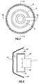
Fig. 3 is a top view of a third embodiment of the invention; -
Fig. 4 is an elevational cross section view of the third embodiment of the invention taken along line 4-4; -
Fig. 4a is an elevational cross section view of the third embodiment of the invention taken alongline 4a-4a; and -
Fig. 5 is a top view of the first embodiment of the invention. - The instant invention is a marine life protection system for use with a water intake system disposed to remove water from a water body through a water inlet and a method for protecting marine life inhabitants of a water body from entrainment in a water intake system
- The marine life protection system for use with a water intake system disposed to remove water from a water body through a water inlet according to the present invention comprises: a decanting wall spaced an effective distance from the water inlet thereby forming a horizontal critical intake zone, wherein the decanting wall extends above a surface of the water body; and a gas source capable of producing bubbles of a gas within the water body, wherein the gas source is spaced apart from, and on an opposite side of the decanting wall as the water inlet, and extending a length at least sufficient to surround the decanting wall; wherein the gas is selected from the group consisting of air, oxygen-enriched air, oxygen, nitrogen, and carbon dioxide.
- Referring to
Fig. 1 , it can be seen that in some instances a water intake system housed in a water intake building 1 having a substantially vertically disposedwater inlet 2 may be located near or abutting a shore orland edge 9 of awater body 10 having awater surface 8 and awater body floor 7. In certain water bodies, the level of thewater surface 8 may change over time, by natural causes such as tides, seasons, and rain amounts, or by man-made causes, such as dam flow or lock adjustments. - In a first embodiment, the marine life protection system comprises a
decanting wall 3. Thedecanting wall 3 preferably extends above the highest level of thewater surface 8, such as the high tide level. Thedecanting wall 3 is sufficiently sized to extend beyond the opening formed by thewater inlet 2. Thedecanting wall 3 is spaced apart fromwater inlet 2 forming a horizontalcritical intake zone 4. Spaced apart from thedecanting wall 3 is agas source 5. Thegas source 5 releases a gas and is configured such that the released gas forms abubble curtain 6. As can be seen inFig. 1 , thegas source 5 is positioned on a side of thedecanting wall 3 opposite the side of the decanting wall 3on which thewater inlet 2 is located. Water passes from thewater body 10 through the horizontalcritical intake zone 4 and intowater inlet 2. Smaller marine life such as larvae, fish eggs and certain marine flora, however, are excluded from entrainment in the water flowing into thewater inlet 2. First, lower density small marine life particles are excluded from entering thewater inlet 2 as such lower density small marine life particles tend to float toward thewater surface 8 and are excluded by the decanting wall which extends up to or above thewater surface 8. As used herein, the term lower density small marine life particles means those non-mobile small marine life, such as larvae, fish eggs and marine flora particles which have a density equal to or less than the density of thewater body 10. As would be readily understood, the density of thewater body 10 may vary for a number of reasons, for example, depending upon the salt or mineral content of the water. - Higher density small marine life particles will also be excluded from entering the
water inlet 2 as thebubble curtain 6 formed from thegas source 5 will cause such particles to be floated upward along thedecanting wall 3 on the side of thedecanting wall 3 opposite the side on which thewater inlet 2 is located. Thus, such higher density small marine life particles do not reach the horizontalcritical intake zone 4. As used herein, the term "higher density marine life particles" means those non-mobile small marine life, such as larvae, fish eggs and marine flora particles which have a density greater than the density of thewater body 10. As discussed above, the density of thewater body 10 may vary for a number of reasons. - In some instances, lower density marine life particle which may be, for a variety of causes, not near the water body surface, may also be floated upwards by the
bubble curtain 6. For example, lower density larvae may hatch at or near thewater body floor 7 at a location near thewater inlet 2. In such instances, thebubble curtain 6 will function to assist in floating such larvae to thewater surface 8 rather than being entrained in water entering the water inlet. - As used herein, the term "non-mobile small marine life" means those forms of marine life incapable of substantial independent movement, including for example, small marine flora, marine life larvae, such as fish, crustacean and/or coral larvae, marine life gametes and eggs, and young marine life. The term "incapable of substantial independent movement" as used herein means that the marine life particles are not able, on their own power, to resist natural currents of the water body or man-made water movements, such as a suction force caused by a water intake system.
- In some embodiments of the invention, the horizontal
critical intake zone 4 is spaced above, with its lower edge defined by, thewater body floor 7. -
Fig. 2 illustrates a second embodiment of the inventive marine life protection system. The second embodiment of the marine life protection system further comprises abottom plate 11 spaced below the decantingwall 3 and extending a distance at least from thewater inlet 2 to thegas source 5. Together thebottom plate 11, decantingwall 3 and water intake system building 1 form a verticalcritical intake zone 12. The embodiment of the marine life protection system shown inFig. 2 is particularly useful for deeper water bodies in which it would be impractical to have a decantingwall 3 sufficiently large to extend to or above thewater surface 8 while using the water body floor to form acritical intake zone 4. - Each of
Figs. 1 and2 illustratedistances Distances Distance 13 may vary, for example, from 5 cm to 10 m. All individual values and sub ranges from 5 cm to 10 m are included herein and disclosed herein; for example,distance 13 can be from a lower limit of 5, 50, 200, 333, 450, 580, 699, 760, 880 or 990 cm to an upper limit of 10, 100, 300, 500, 700, 900 or 1,000 cm. For example, distance 13A may be in the range of from 5 to 500 cm, or in the alternative,distance 13 may be in the range of from 100 to 600 cm, or in the alternative,distance 13 may be in the range of from 500 to 900 cm, or in the alternative,distance 13 may be in the range of from 5 to 20 cm.Distance 12 may vary, for example, from 5 cm to 10 m. All individual values and sub ranges from 5 cm to 10 m are included herein and disclosed herein; for example,distance 12 can be from a lower limit of 5, 50, 200, 333, 450, 580, 699, 760, 880 or 990 cm to an upper limit of 10, 100, 300, 500, 700, 900 or 1,000 cm. For example,distance 12 may be in the range of from 5 to 500 cm, or in the alternative,distance 12 may be in the range of from 100 to 600 cm, or in the alternative,distance 12 may be in the range of from 500 to 900 cm, or in the alternative,distance 12 may be in the range of from 5 to 20 cm. -
Fig. 3 illustrates a third embodiment of the inventive marine life protection system. The embodiment illustrated inFig. 3 may be particularly useful in instances wherein a water inlet of a water intake system is surrounded wholly or almost wholly by the water body.Fig. 3 illustrates a top cross sectional view of the marine life protection system wherein awater inlet 2 is circumscribed by a decantingwall 3 which, in turn, is circumscribed by abubble curtain 6 produced by a gas source (not shown inFig. 3 ). - As can be seen in
Fig. 3 , thebubble curtain 6 encloses thewater inlet 2. In alternative embodiments, such as that shown inFig. 1 wherein the water inlet backs against aland edge 9, thebubble curtain 6 preferably extends sufficiently so as to cover the space in front of thewater inlet 2 from which water may be drawn into thewater inlet 2. In some such configurations, the bubble curtain extends up to theland edge 9. -
Fig. 4 illustrates an elevational cross sectional view of the third embodiment shown inFig. 3 taken along the line 4-4. InFig. 4 , also shown is abottom plate 16 spaced apart from and below the decantingwall 3 andwater inlet 2. One configuration of awater inlet 2 is shown inFig. 4 in which thewater inlet 2 has two openings, each of which are covered by ascreen 17. In yet another alternative embodiment of the invention, the floor of the water body may be used in lieu of thebottom plate 16. It will be readily understood that while the configuration of thewater inlet 2, decantingwall 3 andgas source 5 are shown in a circular form inFig. 3 , any geometrical closed shape may be used, including for example, square, rectangular, pentagonal, hexagonal and the like as well as any irregular closed shape. It will be understood that the embodiment of the invention shown inFigs. 3 and4 may alternatively be used without a bottom plate in those instances where the system is located sufficiently close to thewater body floor 7. -
Fig. 4a illustrates an elevational cross sectional view of the third embodiment shown inFig. 3 taken along theline 4a-4a. - In another alternative embodiment of the inventive marine life protection system, the water inlet may be only partially circumscribed by the decanting wall. In yet another alternative embodiment of the inventive marine life protection system, the decanting wall may be only partially circumscribed by the gas source.
-
Fig. 5 illustrates a top plan view of one configuration of the embodiment illustrated inFig. 1 . In this embodiment, thebubble curtain 6 is in front of thewater intake 2 withextension land edge 9. Decantingwall 3 may also be extended intoside portions portions Side portions portions water body floor 7, or may be raised some distance, not greater thandistance 12 above thewater body floor 7. The vertical position of each ofside portions portions side portions portions water body surface 8 or not. In some embodiments, the decantingwall 3 will have no side or back extensions, or may have any subset thereof. For example, in one embodiment, there may only be aside portion 20 and aback portion 23. In such embodiment,side portion 20 may extend above the water body floor 7 adistance 12 and extend above thewater body surface 8. In such embodiment, backportion 23 may extend to thewater body floor 7 and under thewater body surface 8. That is, the presence and size of each ofportions - Any gas may be used in the gas source to create the bubble curtain. Preferably, a gas which is not harmful to the marine environment or marine life is used. More preferably, a gas which is beneficial to the marine environment and marine life is used. Exemplary gasses include air, oxygen-enriched air, oxygen, nitrogen, and carbon dioxide. In particular embodiments, the gas is compressed air. In yet other embodiments, the gas is any inert gas.
- Preferably, the bubble curtain used in the invention excludes marine life primarily by the physical effect of flotation and the upwardly flowing water current induced by the bubble curtain. It will be understood that some component of exclusion may also be achieved by a behavioral effect, namely, by aversion of mobile marine life to the bubble curtain. However, such behavioral exclusion primarily impacts adult, mobile fish life and does not impact the smaller, immobile marine life targeted by the present invention.
- The inventive marine life protection system may be adapted to work with conventional methods for preventing entrainment of larger and/or mobile marine life, such as adult fish and crustaceans. For example, conventional screens may be used in a variety of locations of the inventive marine life protection system or within a conventional water intake system. Such screens may include, by way of example, static or rotating screens, as are currently known in the art. Such screen may be placed in alternative embodiments of the inventive system in one or more locations selected from the group consisting of within the water inlet, in front of the water inlet, behind the water inlet, within the critical intake zone, and above the critical intake zone but below the water inlet.
Fig. 2 illustrates the presence ofrotating screen filter 17 in the second embodiment of the inventive marine life protection system. As shown inFig. 2 , thefilter 17 is located adjacent to thewater inlet 2 and within the water intake system building 1. - It will be further appreciated that the bubble curtain and decanting wall will also remove other debris and particles that might block traditional screens, and particularly finer screens. Furthermore, removal of lower density and smaller particles, both debris and marine life, from the water stream by the bubble curtain and decanting wall permits the use of smaller mesh screens without exhibiting greater plugging, as would typically be expected with smaller mesh screens.
- Another conventional system for repelling mobile and/or larger marine life from the water inlet is an acoustic system which projects an infra-sound uncomfortable to such marine life. Preferably the acoustic system would not emit frequencies harmful to marine life. More preferably, the acoustic system would emit an intensity gradient or pulsating acoustic signal such as to repel marine life at an effective distance from the water intake system.
Fig. 2 further shows the use of anacoustic system 18 placed between the water intake system building 1 and the decantingwall 3. - In some embodiments of the inventive marine life protection system, at least 50% of a particular marine fauna or flora species in a water fraction is excluded from entering the water inlet. All values from at least 50% are included herein and disclosed herein. For example, the inventive marine life protection system may be capable of excluding 50%, 55%, 60%,65% 70%, 72%, 74%, 76%, 78%, 80%, 82%, 84%, 86% or 88% of any particular marine fauna or flora species in a water fraction from entering the water inlet.
- Alternative embodiments of the inventive marine life protection system is capable of excluding at least 90 % of any particular marine fauna or flora species in a water fraction from entering the water inlet. All values from at least 90% are included herein and disclosed herein. For example, the inventive marine life protection system may be capable of excluding 90%, 92%, 94%, 96% or 100% of any particular marine fauna or flora species in a water fraction from entering the water inlet.
- According to
claim 8, the instant invention further provides a method for protecting marine life inhabitants of a water body from entrainment in a water intake system, wherein the water intake system comprises a water inlet, the method comprising providing a decanting wall spaced an effective distance from the water inlet thereby forming a critical intake zone, wherein the decanting wall extends above a surface of the water body and producing a gas bubble curtain spaced apart from the decanting wall and on an opposite side of the decanting wall as the water inlet, wherein the bubble curtain extends at least a distance from the critical intake zone to above a lower edge of the decanting wall, and wherein the gas bubble curtain comprises gas bubbles comprising one or more gasses selected from the group consisting of air, oxygen-enriched air, oxygen, nitrogen, and carbon dioxide. - The decanting wall is larger than the water inlet such that outer edges of the decanting wall extend beyond an opening formed by the water inlet. The decanting wall is spaced an effective distance above a floor of the water body and the bubble curtain extends vertically at least a distance between the floor of the water body and a lower edge of the decanting wall.
- Specific embodiments of the inventive method further comprise providing a substantially horizontal bottom plate situated below the decanting wall and extending a horizontal distance at least from the water inlet to the bubble curtain. Such embodiment is particularly useful in those water intake system installations in deeper water bodies or located away from a shore or land edge of the water body.
- As discussed above, certain water intake systems may have a water inlet which is surrounded by the water body. In those instances, the inventive method supplies a decanting wall which wholly or partially circumscribes the water inlet and further provides a gas source capable of generating a bubble curtain which wholly or partially circumscribes the decanting wall.
- In a particular embodiment, the inventive method provides a gas source which utilizes compressed air to generate the bubble curtain.
- In various embodiments of the inventive method, one or more conventional fish exclusion methods are included. For example, the inventive method may also comprise providing one or more filter screens, one or more electric field barriers, and/or one or more acoustic repelling systems.
- In some embodiments of the inventive method, at least 90 % of any particular marine fauna or flora species in a water fraction is excluded from entering the water inlet. All values from at least 90% are included herein and disclosed herein. For example, the method may exclude 90%, 92%, 94%, 96% or 100% of any particular marine fauna or flora species in a water fraction.
Claims (14)
- A marine life protection system for use with a water intake system disposed to remove water from a water body (10) through a water inlet (2), comprising:a decanting wall (3) spaced an effective distance from the water inlet (2) thereby forming a critical intake zone (4), wherein the decanting wall (3) extends above a surface of the water body (10); anda gas source (5) capable of generating a bubble curtain (6) comprised of gas bubbles within the water body (10), wherein the gas source (5) is spaced apart from, and on an opposite side of the decanting wall (3) as the water inlet (2);wherein the gas bubbles comprise a gas selected from the group consisting of air, oxygen-enriched air, oxygen, nitrogen, and carbon dioxide; characterized in thatthe decanting wall (3) is spaced an effective distance above a floor of the water body (10); andthe bubble curtain (6) extends vertically at least a distance between the water body floor (7) and a lower edge of the decanting wall (3); and in that the water inlet (2) abuts a shore or land edge (9) of the water body (10); wherein the decanting wall (3) is larger than the water inlet (2) such that outer edges of the decanting wall (3) extend beyond an opening formed by the water inlet (2).
- The marine life protection system according to Claim 1, further comprising a substantially horizontal bottom plate (11) situated below the decanting wall (3) and extending a horizontal distance at least from the water intake system to the gas source (5); and wherein the bubble curtain (6) extends vertically at least a distance between the bottom plate (11) and a lower edge of the decanting wall (3).
- The marine life protection system according to Claim 2, wherein the water inlet (2) is surrounded by the water body (10), the decanting wall (3) at least partially circumscribes the water inlet (2), and wherein the gas source (5) at least partially circumscribes the decanting wall (3).
- The marine life protection system according to any one of the preceding Claims, wherein the gas is compressed air.
- The marine life protection system according to any one of the preceding Claims, further comprising one or more screen filters situated at a location selected from within the water inlet (2), adjacent to the water inlet (2), within the critical intake zone (4), and adjacent to the critical intake zone (4).
- The marine life protection system according to Claim 5, wherein the one or more screens (17) comprise one or more rotating screens.
- The marine life protection system according to any one of the preceding Claims, further comprising an acoustic system (18) positioned to repel mobile marine life away from the water inlet (2).
- A method for protecting marine life inhabitants of a water body (10) from entrainment in a water intake system, wherein the water intake system comprises a water inlet (2), comprising:providing a decanting wall (3) spaced an effective distance from the water inlet (2) thereby forming a critical intake zone (4), wherein the decanting wall (3) extends above a surface of the water body (10); andproducing a gas bubble curtain (6) spaced apart from the decanting wall (3) and on an opposite side of the decanting wall (3) as the water inlet (2), wherein the bubble curtain (6) extends at least a distance from the critical intake zone (4) to above a lower edge of the decanting wall (3), wherein the decanting wall (3) is spaced an effective distance above a floor of the water body (10), and wherein the bubble curtain (6) extends vertically at least a distance between the water body floor (7) and a lower edge of the decanting wall (3);wherein the gas bubble curtain comprises gas bubbles comprising one or more gasses selected from the group consisting of air, oxygen-enriched air, oxygen, nitrogen, and carbon dioxide; and wherein the water inlet (2) abuts a shore of the water body (10); wherein the decanting wall (3) is larger than the water inlet (2) such that outer edges of the decanting wall (3) extend beyond an opening formed by the water inlet (2).
- The method according to Claim 8, further comprising providing a substantially horizontal bottom plate (11) situated below the decanting wall (3) and extending a horizontal distance at least from the water inlet (2) to the bubble curtain (6).
- The method according to Claim 9, wherein the water inlet (2) is surrounded by the water body (10), wherein the decanting wall (3) at least partially circumscribes the water inlet (2), and wherein the bubble curtain (6) at least partially circumscribes the decanting wall (3).
- The method according to any one of Claims 8-10, wherein the bubble curtain (6) comprises bubbles formed from compressed air.
- The method according to any one of Claims 8-11, further comprising providing one or more screen filters located at one or more positions selected from the areas consisting of within the water inlet (2), adjacent to the water inlet (2), within the critical intake zone (4), and adjacent the critical intake zone (4).
- The method according to Claim 12, wherein the one or more screens (17) comprise one or more rotating screens.
- The method according to any one of Claims 8-13, further comprising providing an acoustic system (18) positioned to repel mobile marine life away from the water inlet (2).
Applications Claiming Priority (2)
| Application Number | Priority Date | Filing Date | Title |
|---|---|---|---|
| US201161542540P | 2011-10-03 | 2011-10-03 | |
| PCT/US2012/051312 WO2013052205A1 (en) | 2011-10-03 | 2012-08-17 | A marine life protection system and method of using same |
Publications (2)
| Publication Number | Publication Date |
|---|---|
| EP2751340A1 EP2751340A1 (en) | 2014-07-09 |
| EP2751340B1 true EP2751340B1 (en) | 2016-11-09 |
Family
ID=46829865
Family Applications (1)
| Application Number | Title | Priority Date | Filing Date |
|---|---|---|---|
| EP12756846.7A Not-in-force EP2751340B1 (en) | 2011-10-03 | 2012-08-17 | A marine life protection system and method of using same |
Country Status (2)
| Country | Link |
|---|---|
| EP (1) | EP2751340B1 (en) |
| WO (1) | WO2013052205A1 (en) |
Families Citing this family (3)
| Publication number | Priority date | Publication date | Assignee | Title |
|---|---|---|---|---|
| JP6419624B2 (en) * | 2015-03-30 | 2018-11-07 | 住友重機械工業株式会社 | Intake system |
| CN111676889B (en) * | 2020-06-22 | 2021-02-02 | 宁夏环筑建设有限公司 | Simulation type protection experimental device for slip form construction of hydraulic engineering |
| WO2025250024A1 (en) * | 2024-05-30 | 2025-12-04 | Dehlsen Associates Of The Pacific Limited | Hybrid water/power generation system |
Family Cites Families (3)
| Publication number | Priority date | Publication date | Assignee | Title |
|---|---|---|---|---|
| US2860600A (en) * | 1955-02-07 | 1958-11-18 | Pacific Gas And Electric Co | Diverting fish air bubble screen |
| US6641328B1 (en) * | 1999-03-18 | 2003-11-04 | Balaton Power Corporation S.A. | Fish protective water extraction method and apparatus |
| KR100558267B1 (en) * | 2004-01-03 | 2006-03-10 | 한국해양연구원 | Marine Life Removal System and Removal Method |
-
2012
- 2012-08-17 EP EP12756846.7A patent/EP2751340B1/en not_active Not-in-force
- 2012-08-17 WO PCT/US2012/051312 patent/WO2013052205A1/en not_active Ceased
Also Published As
| Publication number | Publication date |
|---|---|
| WO2013052205A1 (en) | 2013-04-11 |
| EP2751340A1 (en) | 2014-07-09 |
Similar Documents
| Publication | Publication Date | Title |
|---|---|---|
| Coleman et al. | Sedimentation in a Malaysian high tide tropical delta | |
| KR102291227B1 (en) | Eco-friendly dredger for pollutants sediment of sea bottom | |
| KR20170046383A (en) | A floating garbage collecting device | |
| WO2013052205A1 (en) | A marine life protection system and method of using same | |
| JP5824107B2 (en) | Water quality improvement method | |
| US20110297595A1 (en) | Desalination intake system with net positive impact on habitat | |
| KR101702113B1 (en) | Apparatus for smartly managing red tide in submersible fish cage | |
| Hofstede | Integrated management of artificially created salt marshes in the Wadden Sea of Schleswig-Holstein, Germany | |
| JP3535819B2 (en) | Water quality conservation device and method | |
| KR102060726B1 (en) | Underwater barrier | |
| JP5726234B2 (en) | Aoko collection device | |
| JP5869375B2 (en) | Seawater infiltration device | |
| CN100361902C (en) | Water pollution prevention method and water flow partition wall | |
| Pincetti | Sustainable coastal development: a comparative analysis of environmental impacts between floating platforms and dredging | |
| KR100541838B1 (en) | Revetment block installation structure at the bottom of river for reducing the flow velocity | |
| JP2005125227A (en) | Apparatus and method for preventing eutrophication in closed water area using aquatic plant | |
| JP6267672B2 (en) | Dredge apparatus and dredge method | |
| Montagna et al. | Evaluation of the proposal for widening and deepening the Matagorda Ship Channel | |
| RU58130U1 (en) | FISH PROTECTION DEVICE FOR WATER INTAKE STRUCTURE | |
| Bruun | Engineering projects in coastal lagoons | |
| RU2299292C2 (en) | Umbrella-shaped fish protective device | |
| Sonnichsen Jr et al. | Review of thermal power plant intake structure designs and related environmental considerations | |
| RU2622886C2 (en) | Methods of protecting against fouling and protecting fish and fish protection device of complex effect | |
| JP3643007B2 (en) | Water surface flow generator | |
| RU2257445C2 (en) | Fish protection structure of water intake facility |
Legal Events
| Date | Code | Title | Description |
|---|---|---|---|
| PUAI | Public reference made under article 153(3) epc to a published international application that has entered the european phase |
Free format text: ORIGINAL CODE: 0009012 |
|
| 17P | Request for examination filed |
Effective date: 20140324 |
|
| AK | Designated contracting states |
Kind code of ref document: A1 Designated state(s): AL AT BE BG CH CY CZ DE DK EE ES FI FR GB GR HR HU IE IS IT LI LT LU LV MC MK MT NL NO PL PT RO RS SE SI SK SM TR |
|
| DAX | Request for extension of the european patent (deleted) | ||
| REG | Reference to a national code |
Ref country code: DE Ref legal event code: R079 Ref document number: 602012025174 Country of ref document: DE Free format text: PREVIOUS MAIN CLASS: E02B0001000000 Ipc: A01K0079020000 |
|
| GRAP | Despatch of communication of intention to grant a patent |
Free format text: ORIGINAL CODE: EPIDOSNIGR1 |
|
| RIC1 | Information provided on ipc code assigned before grant |
Ipc: A01K 79/02 20060101AFI20160509BHEP |
|
| INTG | Intention to grant announced |
Effective date: 20160530 |
|
| GRAS | Grant fee paid |
Free format text: ORIGINAL CODE: EPIDOSNIGR3 |
|
| GRAA | (expected) grant |
Free format text: ORIGINAL CODE: 0009210 |
|
| AK | Designated contracting states |
Kind code of ref document: B1 Designated state(s): AL AT BE BG CH CY CZ DE DK EE ES FI FR GB GR HR HU IE IS IT LI LT LU LV MC MK MT NL NO PL PT RO RS SE SI SK SM TR |
|
| REG | Reference to a national code |
Ref country code: GB Ref legal event code: FG4D |
|
| REG | Reference to a national code |
Ref country code: AT Ref legal event code: REF Ref document number: 843026 Country of ref document: AT Kind code of ref document: T Effective date: 20161115 Ref country code: CH Ref legal event code: EP |
|
| REG | Reference to a national code |
Ref country code: IE Ref legal event code: FG4D |
|
| REG | Reference to a national code |
Ref country code: DE Ref legal event code: R096 Ref document number: 602012025174 Country of ref document: DE |
|
| PG25 | Lapsed in a contracting state [announced via postgrant information from national office to epo] |
Ref country code: LV Free format text: LAPSE BECAUSE OF FAILURE TO SUBMIT A TRANSLATION OF THE DESCRIPTION OR TO PAY THE FEE WITHIN THE PRESCRIBED TIME-LIMIT Effective date: 20161109 |
|
| REG | Reference to a national code |
Ref country code: LT Ref legal event code: MG4D |
|
| REG | Reference to a national code |
Ref country code: NL Ref legal event code: MP Effective date: 20161109 |
|
| REG | Reference to a national code |
Ref country code: AT Ref legal event code: MK05 Ref document number: 843026 Country of ref document: AT Kind code of ref document: T Effective date: 20161109 |
|
| PG25 | Lapsed in a contracting state [announced via postgrant information from national office to epo] |
Ref country code: LT Free format text: LAPSE BECAUSE OF FAILURE TO SUBMIT A TRANSLATION OF THE DESCRIPTION OR TO PAY THE FEE WITHIN THE PRESCRIBED TIME-LIMIT Effective date: 20161109 Ref country code: SE Free format text: LAPSE BECAUSE OF FAILURE TO SUBMIT A TRANSLATION OF THE DESCRIPTION OR TO PAY THE FEE WITHIN THE PRESCRIBED TIME-LIMIT Effective date: 20161109 Ref country code: NL Free format text: LAPSE BECAUSE OF FAILURE TO SUBMIT A TRANSLATION OF THE DESCRIPTION OR TO PAY THE FEE WITHIN THE PRESCRIBED TIME-LIMIT Effective date: 20161109 Ref country code: GR Free format text: LAPSE BECAUSE OF FAILURE TO SUBMIT A TRANSLATION OF THE DESCRIPTION OR TO PAY THE FEE WITHIN THE PRESCRIBED TIME-LIMIT Effective date: 20170210 Ref country code: NO Free format text: LAPSE BECAUSE OF FAILURE TO SUBMIT A TRANSLATION OF THE DESCRIPTION OR TO PAY THE FEE WITHIN THE PRESCRIBED TIME-LIMIT Effective date: 20170209 |
|
| PG25 | Lapsed in a contracting state [announced via postgrant information from national office to epo] |
Ref country code: PT Free format text: LAPSE BECAUSE OF FAILURE TO SUBMIT A TRANSLATION OF THE DESCRIPTION OR TO PAY THE FEE WITHIN THE PRESCRIBED TIME-LIMIT Effective date: 20170309 Ref country code: PL Free format text: LAPSE BECAUSE OF FAILURE TO SUBMIT A TRANSLATION OF THE DESCRIPTION OR TO PAY THE FEE WITHIN THE PRESCRIBED TIME-LIMIT Effective date: 20161109 Ref country code: ES Free format text: LAPSE BECAUSE OF FAILURE TO SUBMIT A TRANSLATION OF THE DESCRIPTION OR TO PAY THE FEE WITHIN THE PRESCRIBED TIME-LIMIT Effective date: 20161109 Ref country code: FI Free format text: LAPSE BECAUSE OF FAILURE TO SUBMIT A TRANSLATION OF THE DESCRIPTION OR TO PAY THE FEE WITHIN THE PRESCRIBED TIME-LIMIT Effective date: 20161109 Ref country code: HR Free format text: LAPSE BECAUSE OF FAILURE TO SUBMIT A TRANSLATION OF THE DESCRIPTION OR TO PAY THE FEE WITHIN THE PRESCRIBED TIME-LIMIT Effective date: 20161109 Ref country code: IS Free format text: LAPSE BECAUSE OF FAILURE TO SUBMIT A TRANSLATION OF THE DESCRIPTION OR TO PAY THE FEE WITHIN THE PRESCRIBED TIME-LIMIT Effective date: 20170309 Ref country code: RS Free format text: LAPSE BECAUSE OF FAILURE TO SUBMIT A TRANSLATION OF THE DESCRIPTION OR TO PAY THE FEE WITHIN THE PRESCRIBED TIME-LIMIT Effective date: 20161109 Ref country code: AT Free format text: LAPSE BECAUSE OF FAILURE TO SUBMIT A TRANSLATION OF THE DESCRIPTION OR TO PAY THE FEE WITHIN THE PRESCRIBED TIME-LIMIT Effective date: 20161109 |
|
| PG25 | Lapsed in a contracting state [announced via postgrant information from national office to epo] |
Ref country code: RO Free format text: LAPSE BECAUSE OF FAILURE TO SUBMIT A TRANSLATION OF THE DESCRIPTION OR TO PAY THE FEE WITHIN THE PRESCRIBED TIME-LIMIT Effective date: 20161109 Ref country code: CZ Free format text: LAPSE BECAUSE OF FAILURE TO SUBMIT A TRANSLATION OF THE DESCRIPTION OR TO PAY THE FEE WITHIN THE PRESCRIBED TIME-LIMIT Effective date: 20161109 Ref country code: EE Free format text: LAPSE BECAUSE OF FAILURE TO SUBMIT A TRANSLATION OF THE DESCRIPTION OR TO PAY THE FEE WITHIN THE PRESCRIBED TIME-LIMIT Effective date: 20161109 Ref country code: SK Free format text: LAPSE BECAUSE OF FAILURE TO SUBMIT A TRANSLATION OF THE DESCRIPTION OR TO PAY THE FEE WITHIN THE PRESCRIBED TIME-LIMIT Effective date: 20161109 Ref country code: DK Free format text: LAPSE BECAUSE OF FAILURE TO SUBMIT A TRANSLATION OF THE DESCRIPTION OR TO PAY THE FEE WITHIN THE PRESCRIBED TIME-LIMIT Effective date: 20161109 |
|
| REG | Reference to a national code |
Ref country code: DE Ref legal event code: R097 Ref document number: 602012025174 Country of ref document: DE |
|
| PG25 | Lapsed in a contracting state [announced via postgrant information from national office to epo] |
Ref country code: SM Free format text: LAPSE BECAUSE OF FAILURE TO SUBMIT A TRANSLATION OF THE DESCRIPTION OR TO PAY THE FEE WITHIN THE PRESCRIBED TIME-LIMIT Effective date: 20161109 Ref country code: BE Free format text: LAPSE BECAUSE OF FAILURE TO SUBMIT A TRANSLATION OF THE DESCRIPTION OR TO PAY THE FEE WITHIN THE PRESCRIBED TIME-LIMIT Effective date: 20161109 Ref country code: IT Free format text: LAPSE BECAUSE OF FAILURE TO SUBMIT A TRANSLATION OF THE DESCRIPTION OR TO PAY THE FEE WITHIN THE PRESCRIBED TIME-LIMIT Effective date: 20161109 Ref country code: BG Free format text: LAPSE BECAUSE OF FAILURE TO SUBMIT A TRANSLATION OF THE DESCRIPTION OR TO PAY THE FEE WITHIN THE PRESCRIBED TIME-LIMIT Effective date: 20170209 |
|
| PLBE | No opposition filed within time limit |
Free format text: ORIGINAL CODE: 0009261 |
|
| STAA | Information on the status of an ep patent application or granted ep patent |
Free format text: STATUS: NO OPPOSITION FILED WITHIN TIME LIMIT |
|
| 26N | No opposition filed |
Effective date: 20170810 |
|
| PGFP | Annual fee paid to national office [announced via postgrant information from national office to epo] |
Ref country code: DE Payment date: 20170808 Year of fee payment: 6 |
|
| PG25 | Lapsed in a contracting state [announced via postgrant information from national office to epo] |
Ref country code: SI Free format text: LAPSE BECAUSE OF FAILURE TO SUBMIT A TRANSLATION OF THE DESCRIPTION OR TO PAY THE FEE WITHIN THE PRESCRIBED TIME-LIMIT Effective date: 20161109 |
|
| REG | Reference to a national code |
Ref country code: CH Ref legal event code: PL |
|
| PG25 | Lapsed in a contracting state [announced via postgrant information from national office to epo] |
Ref country code: MC Free format text: LAPSE BECAUSE OF FAILURE TO SUBMIT A TRANSLATION OF THE DESCRIPTION OR TO PAY THE FEE WITHIN THE PRESCRIBED TIME-LIMIT Effective date: 20161109 |
|
| GBPC | Gb: european patent ceased through non-payment of renewal fee |
Effective date: 20170817 |
|
| PG25 | Lapsed in a contracting state [announced via postgrant information from national office to epo] |
Ref country code: LI Free format text: LAPSE BECAUSE OF NON-PAYMENT OF DUE FEES Effective date: 20170831 Ref country code: CH Free format text: LAPSE BECAUSE OF NON-PAYMENT OF DUE FEES Effective date: 20170831 |
|
| REG | Reference to a national code |
Ref country code: FR Ref legal event code: ST Effective date: 20180430 |
|
| REG | Reference to a national code |
Ref country code: IE Ref legal event code: MM4A |
|
| PG25 | Lapsed in a contracting state [announced via postgrant information from national office to epo] |
Ref country code: LU Free format text: LAPSE BECAUSE OF NON-PAYMENT OF DUE FEES Effective date: 20170817 |
|
| PG25 | Lapsed in a contracting state [announced via postgrant information from national office to epo] |
Ref country code: IE Free format text: LAPSE BECAUSE OF NON-PAYMENT OF DUE FEES Effective date: 20170817 Ref country code: GB Free format text: LAPSE BECAUSE OF NON-PAYMENT OF DUE FEES Effective date: 20170817 |
|
| PG25 | Lapsed in a contracting state [announced via postgrant information from national office to epo] |
Ref country code: FR Free format text: LAPSE BECAUSE OF NON-PAYMENT OF DUE FEES Effective date: 20170831 |
|
| PG25 | Lapsed in a contracting state [announced via postgrant information from national office to epo] |
Ref country code: MT Free format text: LAPSE BECAUSE OF NON-PAYMENT OF DUE FEES Effective date: 20170817 |
|
| REG | Reference to a national code |
Ref country code: DE Ref legal event code: R119 Ref document number: 602012025174 Country of ref document: DE |
|
| PG25 | Lapsed in a contracting state [announced via postgrant information from national office to epo] |
Ref country code: HU Free format text: LAPSE BECAUSE OF FAILURE TO SUBMIT A TRANSLATION OF THE DESCRIPTION OR TO PAY THE FEE WITHIN THE PRESCRIBED TIME-LIMIT; INVALID AB INITIO Effective date: 20120817 |
|
| PG25 | Lapsed in a contracting state [announced via postgrant information from national office to epo] |
Ref country code: DE Free format text: LAPSE BECAUSE OF NON-PAYMENT OF DUE FEES Effective date: 20190301 |
|
| PG25 | Lapsed in a contracting state [announced via postgrant information from national office to epo] |
Ref country code: CY Free format text: LAPSE BECAUSE OF NON-PAYMENT OF DUE FEES Effective date: 20161109 |
|
| PG25 | Lapsed in a contracting state [announced via postgrant information from national office to epo] |
Ref country code: MK Free format text: LAPSE BECAUSE OF FAILURE TO SUBMIT A TRANSLATION OF THE DESCRIPTION OR TO PAY THE FEE WITHIN THE PRESCRIBED TIME-LIMIT Effective date: 20161109 |
|
| PG25 | Lapsed in a contracting state [announced via postgrant information from national office to epo] |
Ref country code: TR Free format text: LAPSE BECAUSE OF FAILURE TO SUBMIT A TRANSLATION OF THE DESCRIPTION OR TO PAY THE FEE WITHIN THE PRESCRIBED TIME-LIMIT Effective date: 20161109 |
|
| PG25 | Lapsed in a contracting state [announced via postgrant information from national office to epo] |
Ref country code: AL Free format text: LAPSE BECAUSE OF FAILURE TO SUBMIT A TRANSLATION OF THE DESCRIPTION OR TO PAY THE FEE WITHIN THE PRESCRIBED TIME-LIMIT Effective date: 20161109 |