EP2750621B1 - Micro-robot motion controlling system utilizing dual source x-ray ct equipment - Google Patents
Micro-robot motion controlling system utilizing dual source x-ray ct equipment Download PDFInfo
- Publication number
- EP2750621B1 EP2750621B1 EP12828898.2A EP12828898A EP2750621B1 EP 2750621 B1 EP2750621 B1 EP 2750621B1 EP 12828898 A EP12828898 A EP 12828898A EP 2750621 B1 EP2750621 B1 EP 2750621B1
- Authority
- EP
- European Patent Office
- Prior art keywords
- unit
- micro
- robot
- ray
- image
- Prior art date
- Legal status (The legal status is an assumption and is not a legal conclusion. Google has not performed a legal analysis and makes no representation as to the accuracy of the status listed.)
- Not-in-force
Links
Images


Classifications
-
- A—HUMAN NECESSITIES
- A61—MEDICAL OR VETERINARY SCIENCE; HYGIENE
- A61B—DIAGNOSIS; SURGERY; IDENTIFICATION
- A61B6/00—Apparatus or devices for radiation diagnosis; Apparatus or devices for radiation diagnosis combined with radiation therapy equipment
- A61B6/02—Arrangements for diagnosis sequentially in different planes; Stereoscopic radiation diagnosis
- A61B6/03—Computed tomography [CT]
- A61B6/032—Transmission computed tomography [CT]
-
- B—PERFORMING OPERATIONS; TRANSPORTING
- B25—HAND TOOLS; PORTABLE POWER-DRIVEN TOOLS; MANIPULATORS
- B25J—MANIPULATORS; CHAMBERS PROVIDED WITH MANIPULATION DEVICES
- B25J13/00—Controls for manipulators
- B25J13/08—Controls for manipulators by means of sensing devices, e.g. viewing or touching devices
-
- A—HUMAN NECESSITIES
- A61—MEDICAL OR VETERINARY SCIENCE; HYGIENE
- A61B—DIAGNOSIS; SURGERY; IDENTIFICATION
- A61B34/00—Computer-aided surgery; Manipulators or robots specially adapted for use in surgery
- A61B34/70—Manipulators specially adapted for use in surgery
- A61B34/72—Micromanipulators
-
- A—HUMAN NECESSITIES
- A61—MEDICAL OR VETERINARY SCIENCE; HYGIENE
- A61B—DIAGNOSIS; SURGERY; IDENTIFICATION
- A61B6/00—Apparatus or devices for radiation diagnosis; Apparatus or devices for radiation diagnosis combined with radiation therapy equipment
-
- A—HUMAN NECESSITIES
- A61—MEDICAL OR VETERINARY SCIENCE; HYGIENE
- A61B—DIAGNOSIS; SURGERY; IDENTIFICATION
- A61B6/00—Apparatus or devices for radiation diagnosis; Apparatus or devices for radiation diagnosis combined with radiation therapy equipment
- A61B6/02—Arrangements for diagnosis sequentially in different planes; Stereoscopic radiation diagnosis
- A61B6/03—Computed tomography [CT]
- A61B6/032—Transmission computed tomography [CT]
- A61B6/035—Mechanical aspects of CT
-
- A—HUMAN NECESSITIES
- A61—MEDICAL OR VETERINARY SCIENCE; HYGIENE
- A61B—DIAGNOSIS; SURGERY; IDENTIFICATION
- A61B6/00—Apparatus or devices for radiation diagnosis; Apparatus or devices for radiation diagnosis combined with radiation therapy equipment
- A61B6/12—Arrangements for detecting or locating foreign bodies
-
- A—HUMAN NECESSITIES
- A61—MEDICAL OR VETERINARY SCIENCE; HYGIENE
- A61B—DIAGNOSIS; SURGERY; IDENTIFICATION
- A61B6/00—Apparatus or devices for radiation diagnosis; Apparatus or devices for radiation diagnosis combined with radiation therapy equipment
- A61B6/40—Arrangements for generating radiation specially adapted for radiation diagnosis
- A61B6/4007—Arrangements for generating radiation specially adapted for radiation diagnosis characterised by using a plurality of source units
- A61B6/4014—Arrangements for generating radiation specially adapted for radiation diagnosis characterised by using a plurality of source units arranged in multiple source-detector units
-
- B—PERFORMING OPERATIONS; TRANSPORTING
- B25—HAND TOOLS; PORTABLE POWER-DRIVEN TOOLS; MANIPULATORS
- B25J—MANIPULATORS; CHAMBERS PROVIDED WITH MANIPULATION DEVICES
- B25J19/00—Accessories fitted to manipulators, e.g. for monitoring, for viewing; Safety devices combined with or specially adapted for use in connection with manipulators
- B25J19/02—Sensing devices
-
- A—HUMAN NECESSITIES
- A61—MEDICAL OR VETERINARY SCIENCE; HYGIENE
- A61B—DIAGNOSIS; SURGERY; IDENTIFICATION
- A61B90/00—Instruments, implements or accessories specially adapted for surgery or diagnosis and not covered by any of the groups A61B1/00 - A61B50/00, e.g. for luxation treatment or for protecting wound edges
- A61B90/36—Image-producing devices or illumination devices not otherwise provided for
- A61B90/37—Surgical systems with images on a monitor during operation
- A61B2090/376—Surgical systems with images on a monitor during operation using X-rays, e.g. fluoroscopy
Definitions
- the present invention relates, in general, to a system for controlling a position of a micro-robot using a dual source X-ray image device and, more particularly, to a system for precisely controlling a position of a micro-robot, which is electromagnetically driven, using a dual source X-ray image device.
- an X-ray computer tomography (CT) scanner includes an X-ray source and an X-ray detector, wherein X-rays generated from the X-ray source are emitted onto and transmitted through a target object so that the X-ray detector detects the transmitted X-rays and stores measured data, which are then re-configured into images using a computer.
- CT computer tomography
- a dual source X-ray image device includes two X-ray sources which are arranged perpendicular to each other in order to emit X-rays from upper and side portions of a target object, and two X-ray detectors which are positioned opposite the two X-ray sources, whereby two-dimensional images are obtained for the plane and side of the target object. The two-dimensional images are then matched with each other, obtaining three-dimensional information.
- micro-robot Minimally invasive operations using a micro-robot have recently been studied. In these operations, a dissection is minimized to reduce a patient's pain and shorten the convalescence period after an operation.
- a micro-robot is very small and needs the operations of its body to be precision operations so that a position of the micro-robot can be precisely controlled.
- the micro-robot may be driven in an electromagnetic manner, e.g. using an electromagnetic drive, which includes Helmholtz coils, Maxwell coils and saddle coils so as to precisely drive the micro-robot (see Korean unexamined patent publication No. 10-2011-0000779 published on January 6, 2011 ).
- an electromagnetic drive which includes Helmholtz coils, Maxwell coils and saddle coils so as to precisely drive the micro-robot (see Korean unexamined patent publication No. 10-2011-0000779 published on January 6, 2011 ).
- the three-dimensional position of the micro-robot must be checked in real-time and variations that occur in the external environment should affect a control signal that will drive the micro-robot.
- KR 20110000779 A discloses a three-dimensional electromagnetic actuation device for driving a micro-robot comprising a main casing, a rotatable gradient saddle coil, a cylindrical casing with a gear portion and a control unit.
- US 2007038063 A1 discloses a magnetic navigation device for controlling an endoscopy capsule.
- the magnetic navigation device comprises a coil system with a plurality of separate coils and an X-ray machine with a radiation source and a solid state radiation detector.
- DE 102007043729 A1 discloses a medical system for controlling a medical instrument, such as an endoscopy capsule.
- the system comprises a magnetic coil system with a plurality of single coils, X-ray emitters and X-ray detectors.
- the present invention has been made keeping in mind the above problems occurring in the related art. It is intended to provide a system and method for precisely controlling a position of an electromagnetically driven micro-robot using a dual source X-ray image device.
- the present invention provides a system according to claim 1.
- control unit may include: an image data processing module which processes image data obtained from the image pick-up unit; a matching module which obtains a coordinate and vector information of the micro-robot using image data from the processing module and a driving rotary angle of the drive unit; and a control module which controls the power supply to the coil unit to control the position of the micro-robot, using the coordinate and vector information obtained by the matching module.
- the image data processing module may further include a display for displaying a processed image onto a screen.
- the coil unit may include a pair of Helmholtz coils arranged opposite each other, and the image pick-up unit may be fixedly provided on a vertical plane between the pair of Helmholtz coils.
- the two X-ray sources may be arranged perpendicular to each other.
- a method of controlling a position of an electromagnetically driven micro-robot using a dual source X-ray image device including controlling the position of the micro-robot by obtaining a three-dimensional computer tomography image using X-rays from the dual X-ray sources and matching the three-dimensional image with a real-time image by adapting coordinate and vector information of the micro-robot as a feedback signal.
- a coil unit for driving the micro-robot electromagnetically and the dual source X-ray image device for emitting and detecting X-rays from the two X-ray sources may be arranged perpendicular to each other and synchronously rotated to control the position of the micro-robot.
- the coil unit may include a pair of Helmholtz coils arranged opposite each other, and the dual source X-ray image device may be fixedly provided on a vertical plane between the pair of Helmholtz coils.
- the system for controlling the position of the micro-robot can exert precision control over the micro-robot, because the coil unit that is electromagnetically driving the micro-robot and the dual source X-ray image device that is capable of tracking the position of the micro-robot are coupled together and thus are rotation-driven by a single drive unit.
- the method of controlling the position of the micro-robot can precisely control the micro-robot by matching the three-dimensional computer tomography image obtained using the dual source X-rays with the real-time image and using the coordinate and vector information of the micro-robot as a feedback signal.
- a system for controlling the position of a micro-robot using a dual source X-ray image device includes a main body 100, an image pick-up unit 110 using dual X-ray sources and placed on the main body 100, a coil unit 120 for driving the micro-robot, a drive unit 130 for driving the image pick-up unit 110 and the coil unit 120 relative to the main unit, and a control unit controlling the coil unit 120 or the drive unit 130 based on image data obtained from the image pick-up unit 110 to control a position of the micro-robot.
- the image pick-up unit 110, the coil unit 120, the drive unit 130, a platform on which a target object is placed, and other peripheral devices are installed on the main body 100.
- rolling wheels may be provided on a lower portion of the main body so that the main body can be easily moved to the desired position.
- the image pick-up unit 110 is a unit that obtains 3-dimensional position data using bi-plane image data for a 2-dimensional plane and side face, which are obtained using dual source X-rays.
- the image pick-up unit may include two X-ray sources 111a and 111b arranged perpendicular to each other and two X-ray detectors 112a and 112b detecting X-rays emitted from the X-ray sources.
- the X-ray detector consists of an array of sensors for detecting 2-dimensional image data.
- the coil unit 120 may include a variety of coils in order to electromagnetically drive the micro-robot.
- the coil unit 120 may include a pair of Helmholtz coils 121 arranged opposite each other, a pair of Maxwell coils 122 coaxially positioned with the Helmholtz coils 121, and the saddle coils 123 passing through the inside of the Helmholtz coils 121 and the Maxwell coils 122.
- the Helmholtz coil 121 and the saddle coils 123 are the coils that magnetizes the micro-robot and determines the forward direction
- the Maxwell coil 122 and the saddle coils 123 are the coils that interact with the magnetized force of the micro-robot according to the direction and size of the current applied thereto so as to provide thrust force to the micro-robot.
- the construction of the coil unit is not limited to a specified form, but may adopt various types of forms.
- the coil for the provision of the thrust force of the micro-robot may have diversified forms in order to provide more effective thrust force by taking into account the shapes or functions of the micro-robot.
- the coil unit and the image pick-up unit may be arranged such that at least they do not interfere with each other.
- the image pick-up unit consisting of two X-ray sources 111a and 111b and two X-ray detectors 112a and 112b is arranged on a single plane (zy plane) such that it is fixedly arranged on a vertical plane between the pair of Helmholtz coils 121.
- coils for providing the micro-robot with thrust force and the Helmholtz coils may be arranged in an arrangement which does not hinder the image pick-up unit from obtaining image data.
- the pair of Maxwell coils 122 may be arranged opposite each other on the axis on which the Helmholtz coils 121 are arranged, and the saddle coils 123 may pass through the inside of the Helmholtz coils 121 and the Maxwell coils 122.
- the image pick-up unit is fixedly arranged in a space between the Helmholtz coils and the Maxwell coils which is defined by vertical planes, such that it does not interfere with the saddle coils 123.
- the image pick-up unit is synchronously rotated when the coil unit is rotated.
- two stationary frames 101 and 102 are provided vertically, and first and second rotary frames 103 and 104 are coupled to each other by a plurality of fixing beams 105 such that the rotary frames are rotatable between the stationary frames 101 and 102.
- the X-ray source 111a and the X-ray detector 111b of the image pick-up unit are fixed to the fixing beams 105.
- the coil unit 120 is fixedly installed to the first and second rotary frames 103 and 104 or the fixing beams 105, so that the coil unit rotates together with the image pick-up unit 110.
- the second rotary frame 104 is provided with a slewing gear 106, which is rotated by a single drive unit 130.
- the drive unit 130 consists of a motor 131 and a reduction gear, wherein the driving force of the motor 131 is transmitted to the slewing gear 106 via the reduction gear.
- the image pick-up unit 110, the coil unit 120, and the drive unit 130, which are provided in the main body 100, are controlled by the control unit in order to precisely control the position of the micro-robot.
- control unit 200 may include an image data processing module 210 that processes image data obtained from the image pick-up unit; a matching module 220 that obtains coordinate and vector information of the micro-robot using image data from the processing module and a driving rotary angle of the drive unit; and a control module 230 that controls the power supply to the coil unit 120 in order to control the position of the micro-robot, using the coordinate and vector information obtained by the matching module 220.
- the image data processing module 210 obtains image data 212 for two 2-dimensional planes (e.g., the xy- and yz-planes in FIG. 2 ) from the two X-ray detectors 112a and 112b provided in the main body 100, and then obtains a 3-dimensional computer tomography image 211 by matching using two 2-D plane image data.
- two 2-dimensional planes e.g., the xy- and yz-planes in FIG. 2
- the image data processing module 210 obtains image data 212 for two 2-dimensional planes (e.g., the xy- and yz-planes in FIG. 2 ) from the two X-ray detectors 112a and 112b provided in the main body 100, and then obtains a 3-dimensional computer tomography image 211 by matching using two 2-D plane image data.
- the image data processing module 210 may further include a display 213 such as a monitor for outputting a real-time X-ray image or a 3-D computer tomography image to the outside.
- a display 213 such as a monitor for outputting a real-time X-ray image or a 3-D computer tomography image to the outside.
- the matching module 220 obtains the coordinate and vector information about the position of the micro-robot by going through a matching process using the rotary angle transmitted from an encoder 131, which is connected to the drive unit 130, together with the 3-D computer tomography image from the image data processing module 210 and the real-time X-ray image.
- the control nodule 230 precisely controls the position of the micro-robot by rotating the drive unit 130 or controlling a power supply 250, which is connected to the coil unit 120, using the coordinate and vector information about the position of the micro-robot, which are obtained by the matching module 220, as feedback signals.
- a BP converter 241 which detects and converts a blood pressure of a target object into an electric signal
- a compensating module 242 which receives the signal from the BP converter 241 and calculates a compensating value by analyzing the pulsatory blood flow are further provided, so that the compensating value produced by analyzing the pulsatory blood flow is applied to the control signal output from the control module 230, thereby precisely controlling the position of the micro-robot.
- the system for controlling the position of the micro-robot can exert precision control over the micro-robot because of the coil unit that electromagnetically drives the micro-robot and the dual source X-ray image device which are arranged together such that they do not interfere with each other, and thus are rotation-driven by a single drive unit and because the three-dimensional computer tomography image obtained using the dual source X-rays is matched with the real-time image and then exerting real time control over the rotation of the coil unit or over the regulation of the power supply to the coil unit, using the coordinate and vector information about the position of the micro-robot as feedback signals.
- the system can obtain 3-D computer tomography images using X-ray images which are obtained by rotating the image pick-up unit 110, and such 3-D computer tomography images can replace existing pre-operational images.
- This provides the advantages of omitting image-matching between a pre-operational image and an intra-operational image, as takes place in a conventional operation method thereby eliminating the need for a fiducial marker to conduct matching.
Landscapes
- Health & Medical Sciences (AREA)
- Engineering & Computer Science (AREA)
- Life Sciences & Earth Sciences (AREA)
- Medical Informatics (AREA)
- Surgery (AREA)
- Heart & Thoracic Surgery (AREA)
- Molecular Biology (AREA)
- Nuclear Medicine, Radiotherapy & Molecular Imaging (AREA)
- Veterinary Medicine (AREA)
- Public Health (AREA)
- General Health & Medical Sciences (AREA)
- Biomedical Technology (AREA)
- Animal Behavior & Ethology (AREA)
- Radiology & Medical Imaging (AREA)
- Biophysics (AREA)
- Physics & Mathematics (AREA)
- High Energy & Nuclear Physics (AREA)
- Pathology (AREA)
- Optics & Photonics (AREA)
- Robotics (AREA)
- Pulmonology (AREA)
- Theoretical Computer Science (AREA)
- Mechanical Engineering (AREA)
- Human Computer Interaction (AREA)
- Apparatus For Radiation Diagnosis (AREA)
Description
- The present invention relates, in general, to a system for controlling a position of a micro-robot using a dual source X-ray image device and, more particularly, to a system for precisely controlling a position of a micro-robot, which is electromagnetically driven, using a dual source X-ray image device.
- Generally, an X-ray computer tomography (CT) scanner includes an X-ray source and an X-ray detector, wherein X-rays generated from the X-ray source are emitted onto and transmitted through a target object so that the X-ray detector detects the transmitted X-rays and stores measured data, which are then re-configured into images using a computer.
- In the meantime, while a conventional X-ray CT scanner obtains tomography images of a target object using a single X-ray source, there is also a bi-plane X-ray image device that uses two X-ray sources [see Korean Patent No.
731052 (registered on June 15, 2007 - A dual source X-ray image device includes two X-ray sources which are arranged perpendicular to each other in order to emit X-rays from upper and side portions of a target object, and two X-ray detectors which are positioned opposite the two X-ray sources, whereby two-dimensional images are obtained for the plane and side of the target object. The two-dimensional images are then matched with each other, obtaining three-dimensional information.
- Minimally invasive operations using a micro-robot have recently been studied. In these operations, a dissection is minimized to reduce a patient's pain and shorten the convalescence period after an operation. Such a micro-robot is very small and needs the operations of its body to be precision operations so that a position of the micro-robot can be precisely controlled.
- The micro-robot may be driven in an electromagnetic manner, e.g. using an electromagnetic drive, which includes Helmholtz coils, Maxwell coils and saddle coils so as to precisely drive the micro-robot (see Korean unexamined patent publication No.
10-2011-0000779 published on January 6, 2011 - In the meantime, to precisely control the position of the micro-robot, it is important to precisely detect in real-time the position of the micro-robot and a drive device to precisely drive the micro-robot so as to monitor and control the precise operation of the micro-robot along its pre-established running path.
- Particularly, in order to precisely control the position of the micro-robot in the body, such as in a blood vessel where blood is flowing in a pulsatory manner, the three-dimensional position of the micro-robot must be checked in real-time and variations that occur in the external environment should affect a control signal that will drive the micro-robot.
-
KR 20110000779 A -
US 2007038063 A1 discloses a magnetic navigation device for controlling an endoscopy capsule. The magnetic navigation device comprises a coil system with a plurality of separate coils and an X-ray machine with a radiation source and a solid state radiation detector. -
DE 102007043729 A1 discloses a medical system for controlling a medical instrument, such as an endoscopy capsule. The system comprises a magnetic coil system with a plurality of single coils, X-ray emitters and X-ray detectors. - Accordingly, the present invention has been made keeping in mind the above problems occurring in the related art. It is intended to provide a system and method for precisely controlling a position of an electromagnetically driven micro-robot using a dual source X-ray image device.
- In an aspect, the present invention provides a system according to claim 1.
- In an embodiment, the control unit may include: an image data processing module which processes image data obtained from the image pick-up unit; a matching module which obtains a coordinate and vector information of the micro-robot using image data from the processing module and a driving rotary angle of the drive unit; and a control module which controls the power supply to the coil unit to control the position of the micro-robot, using the coordinate and vector information obtained by the matching module.
- In an embodiment, the image data processing module may further include a display for displaying a processed image onto a screen.
- In an embodiment, the coil unit may include a pair of Helmholtz coils arranged opposite each other, and the image pick-up unit may be fixedly provided on a vertical plane between the pair of Helmholtz coils.
- In an embodiment, the two X-ray sources may be arranged perpendicular to each other.
- According to an example useful for understanding the invention, there is provided a method of controlling a position of an electromagnetically driven micro-robot using a dual source X-ray image device, the method including controlling the position of the micro-robot by obtaining a three-dimensional computer tomography image using X-rays from the dual X-ray sources and matching the three-dimensional image with a real-time image by adapting coordinate and vector information of the micro-robot as a feedback signal.
- A coil unit for driving the micro-robot electromagnetically and the dual source X-ray image device for emitting and detecting X-rays from the two X-ray sources may be arranged perpendicular to each other and synchronously rotated to control the position of the micro-robot.
- The coil unit may include a pair of Helmholtz coils arranged opposite each other, and the dual source X-ray image device may be fixedly provided on a vertical plane between the pair of Helmholtz coils.
- As described above, the system for controlling the position of the micro-robot can exert precision control over the micro-robot, because the coil unit that is electromagnetically driving the micro-robot and the dual source X-ray image device that is capable of tracking the position of the micro-robot are coupled together and thus are rotation-driven by a single drive unit.
- Further, the method of controlling the position of the micro-robot can precisely control the micro-robot by matching the three-dimensional computer tomography image obtained using the dual source X-rays with the real-time image and using the coordinate and vector information of the micro-robot as a feedback signal.
-
-
FIG. 1 is a front view illustrating a portion of a micro-robot control system using a dual source X-ray image device according to the present invention; -
FIG. 2 is a view illustrating a preferred example of a coil unit of the micro-robot control system using the dual source X-ray image device; -
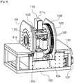
FIG. 3 is a perspective view illustrating a portion of the micro-robot control system using the dual source X-ray image device; and -
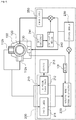
FIG. 4 is a view illustrating the entire construction of the micro-robot control system using the dual source X-ray image device. -
- 100: main body 110: Image pick-up unit
- 120: Coil unit 121: Helmholtz coils
- 122: Maxwell coils 123: Saddle coils
- 130: Drive unit 200: Control unit
- 210: Image data processing module
- 220: Matching module 230: Control module
- Hereinafter, embodiments of the present invention will be described in detail with reference to the accompanying drawings.
- Referring to
FIG. 1 , a system for controlling the position of a micro-robot using a dual source X-ray image device includes amain body 100, an image pick-up unit 110 using dual X-ray sources and placed on themain body 100, acoil unit 120 for driving the micro-robot, adrive unit 130 for driving the image pick-up unit 110 and thecoil unit 120 relative to the main unit, and a control unit controlling thecoil unit 120 or thedrive unit 130 based on image data obtained from the image pick-up unit 110 to control a position of the micro-robot. - The image pick-
up unit 110, thecoil unit 120, thedrive unit 130, a platform on which a target object is placed, and other peripheral devices are installed on themain body 100. Although not shown, rolling wheels may be provided on a lower portion of the main body so that the main body can be easily moved to the desired position. - The image pick-
up unit 110 is a unit that obtains 3-dimensional position data using bi-plane image data for a 2-dimensional plane and side face, which are obtained using dual source X-rays. The image pick-up unit may include twoX-ray sources X-ray detectors - The X-ray detector consists of an array of sensors for detecting 2-dimensional image data.
- The
coil unit 120 may include a variety of coils in order to electromagnetically drive the micro-robot. - Particularly, referring to
FIG. 2 , thecoil unit 120 may include a pair of Helmholtzcoils 121 arranged opposite each other, a pair of Maxwellcoils 122 coaxially positioned with the Helmholtzcoils 121, and thesaddle coils 123 passing through the inside of the Helmholtzcoils 121 and the Maxwellcoils 122. - The Helmholtz
coil 121 and thesaddle coils 123 are the coils that magnetizes the micro-robot and determines the forward direction, and the Maxwellcoil 122 and thesaddle coils 123 are the coils that interact with the magnetized force of the micro-robot according to the direction and size of the current applied thereto so as to provide thrust force to the micro-robot. - In the meantime, the construction of the coil unit is not limited to a specified form, but may adopt various types of forms. Particularly, the coil for the provision of the thrust force of the micro-robot may have diversified forms in order to provide more effective thrust force by taking into account the shapes or functions of the micro-robot.
- The coil unit and the image pick-up unit may be arranged such that at least they do not interfere with each other.
- Particularly, referring to
FIG. 2 , the image pick-up unit consisting of twoX-ray sources X-ray detectors coils 121. - As previously described, coils for providing the micro-robot with thrust force and the Helmholtz coils may be arranged in an arrangement which does not hinder the image pick-up unit from obtaining image data. For example, the pair of Maxwell
coils 122 may be arranged opposite each other on the axis on which the Helmholtzcoils 121 are arranged, and thesaddle coils 123 may pass through the inside of the Helmholtzcoils 121 and the Maxwellcoils 122. In this case, the image pick-up unit is fixedly arranged in a space between the Helmholtz coils and the Maxwell coils which is defined by vertical planes, such that it does not interfere with thesaddle coils 123. - Further, for the position control of the micro-robot, the image pick-up unit is synchronously rotated when the coil unit is rotated.
- Particularly, referring to
FIG. 3 , on themain body 100, twostationary frames rotary frames fixing beams 105 such that the rotary frames are rotatable between thestationary frames X-ray source 111a and theX-ray detector 111b of the image pick-up unit are fixed to the fixing beams 105. Thecoil unit 120 is fixedly installed to the first and second rotary frames 103 and 104 or the fixingbeams 105, so that the coil unit rotates together with the image pick-upunit 110. - The second
rotary frame 104 is provided with aslewing gear 106, which is rotated by asingle drive unit 130. In an embodiment, thedrive unit 130 consists of amotor 131 and a reduction gear, wherein the driving force of themotor 131 is transmitted to theslewing gear 106 via the reduction gear. - The image pick-up
unit 110, thecoil unit 120, and thedrive unit 130, which are provided in themain body 100, are controlled by the control unit in order to precisely control the position of the micro-robot. - Particularly, referring to
FIG. 4 , thecontrol unit 200 may include an imagedata processing module 210 that processes image data obtained from the image pick-up unit; amatching module 220 that obtains coordinate and vector information of the micro-robot using image data from the processing module and a driving rotary angle of the drive unit; and acontrol module 230 that controls the power supply to thecoil unit 120 in order to control the position of the micro-robot, using the coordinate and vector
information obtained by thematching module 220. - The image
data processing module 210 obtainsimage data 212 for two 2-dimensional planes (e.g., the xy- and yz-planes inFIG. 2 ) from the twoX-ray detectors main body 100, and then obtains a 3-dimensionalcomputer tomography image 211 by matching using two 2-D plane image data. - In addition, the image
data processing module 210 may further include adisplay 213 such as a monitor for outputting a real-time X-ray image or a 3-D computer tomography image to the outside. - The
matching module 220 obtains the coordinate and vector information about the position of the micro-robot by going through a matching process using the rotary angle transmitted from anencoder 131, which is connected to thedrive unit 130, together with the 3-D computer tomography image from the imagedata processing module 210 and the real-time X-ray image. - The
control nodule 230 precisely controls the position of the micro-robot by rotating thedrive unit 130 or controlling apower supply 250, which is connected to thecoil unit 120, using the coordinate and vector information about the position of the micro-robot, which are obtained by thematching module 220, as feedback signals. - In the meantime, a
BP converter 241 which detects and converts a blood pressure of a target object into an electric signal, and a compensatingmodule 242 which receives the signal from theBP converter 241 and calculates a compensating value by analyzing the pulsatory blood flow are further provided, so that the compensating value produced by analyzing the pulsatory blood flow is applied to the control signal output from thecontrol module 230, thereby precisely controlling the position of the micro-robot. - As described above, the system for controlling the position of the micro-robot can exert precision control over the micro-robot because of the coil unit that electromagnetically drives the micro-robot and the dual source X-ray image device which are arranged together such that they do not interfere with each other, and thus are rotation-driven by a single drive unit and because the three-dimensional computer tomography image obtained using the dual source X-rays is matched with the real-time image and then exerting real time control over the rotation of the coil unit or over the regulation of the power supply to the coil unit, using the coordinate and vector information about the position of the micro-robot as feedback signals.
- In addition, the system can obtain 3-D computer tomography images using X-ray images which are obtained by rotating the image pick-up
unit 110, and such 3-D computer tomography images can replace existing pre-operational images. This provides the advantages of omitting image-matching between a pre-operational image and an intra-operational image, as takes place in a conventional operation method
thereby eliminating the need for a fiducial marker to conduct matching. - Although the embodiments of the present invention have been disclosed for illustrative purposes, those skilled in the art will appreciate that various modifications, additions and substitutions are possible, without departing from the scope of the invention as disclosed in the accompanying claims.
Claims (5)
- A system for controlling a position of a micro-robot, the system comprising:a main body (100); anda coil unit (120) provided in the main body (100) so as to generate a drive signal to electromechanically drive the micro-robot; characterized in that the system further comprises:an image pick-up unit (110) provided in the main body (100), the image pick-up unit (110) includes two X-ray sources (111a, 111b) and two X-ray detectors (112a, 112b) detecting X-rays emitted from the X-ray sources (111a, 111 b);a drive unit (130) for driving the image pick-up unit (110) and the coil unit (120), being coupled together, relative to the main body (100); anda control unit (200) controlling the coil unit (120) or the drive unit (130) based on image data obtained from the image pick-up unit (110) to control a position of the micro-robot.
- The system according to claim 1, wherein the control unit (200) includes:an image data processing module (210) processing image data obtained from the image pick-up unit (110);a matching module (220) obtaining a coordinate and vector information of the micro-robot using image data processed by the processing module (210) and a driving rotary angle of the drive unit (130); anda control module (230) controlling a power supply to the coil unit (120) to control the position of the micro-robot, using the coordinate and vector information obtained by the matching module (220).
- The system according to claim 2, wherein the image data processing module further includes a display (213) for displaying a processed image onto a screen.
- The system according to claim 1, wherein the coil unit (120) includes a pair of Helmholtz coils arranged opposite each other, and the image pick-up unit (110) is fixedly provided on a vertical plane between the pair of Helm holtz coils.
- The system according to claim 1 or 4, wherein the two X-ray sources (111a, 111 b) are arranged perpendicular to each other.
Applications Claiming Priority (2)
| Application Number | Priority Date | Filing Date | Title |
|---|---|---|---|
| KR1020110087839A KR101198917B1 (en) | 2011-08-31 | 2011-08-31 | Micro-robot motion controlling system utilizing a dual source X-ray CT equipment and method therefor |
| PCT/KR2012/006706 WO2013032172A1 (en) | 2011-08-31 | 2012-08-23 | Micro-robot motion controlling system utilizing dual source x-ray ct equipment and method therefor |
Publications (3)
| Publication Number | Publication Date |
|---|---|
| EP2750621A1 EP2750621A1 (en) | 2014-07-09 |
| EP2750621A4 EP2750621A4 (en) | 2015-04-01 |
| EP2750621B1 true EP2750621B1 (en) | 2017-06-28 |
Family
ID=47564199
Family Applications (1)
| Application Number | Title | Priority Date | Filing Date |
|---|---|---|---|
| EP12828898.2A Not-in-force EP2750621B1 (en) | 2011-08-31 | 2012-08-23 | Micro-robot motion controlling system utilizing dual source x-ray ct equipment |
Country Status (3)
| Country | Link |
|---|---|
| EP (1) | EP2750621B1 (en) |
| KR (1) | KR101198917B1 (en) |
| WO (1) | WO2013032172A1 (en) |
Families Citing this family (5)
| Publication number | Priority date | Publication date | Assignee | Title |
|---|---|---|---|---|
| KR101349984B1 (en) * | 2012-12-28 | 2014-01-16 | 재단법인대구경북과학기술원 | Apparatus for controlling micro robot |
| CZ306843B6 (en) | 2013-08-05 | 2017-08-09 | Ústav teoretické a aplikované mechaniky AV ČR, v.v.i. | Multi-axis equipment for X-ray measurements, in particular computer tomography |
| KR102203928B1 (en) | 2015-03-17 | 2021-01-18 | 한국전자통신연구원 | Method for detecting position of micro robot using ultra wiide band impulse radar and therefore device |
| KR102226282B1 (en) | 2019-02-19 | 2021-03-09 | 전남대학교산학협력단 | System for recognizing position of capsule endoscope by using magnetic induction |
| CN114288567B (en) * | 2022-01-05 | 2022-08-30 | 北京邮电大学 | Robot system capable of performing physical action on biological body surface and tissues below biological body surface |
Family Cites Families (6)
| Publication number | Priority date | Publication date | Assignee | Title |
|---|---|---|---|---|
| DE102005032370A1 (en) * | 2005-07-08 | 2007-01-11 | Siemens Ag | Method for determining the position and orientation of an endoscope capsule for an investigation of the gastrointestinal tract comprises determining the position and orientation of the capsule based on the images produced by an X-ray device |
| DE102007043729A1 (en) | 2007-09-13 | 2009-04-02 | Siemens Ag | Medical system for e.g. endoscopic surgery, has X-ray window arranged in magnetic coil system, and X-ray diagnostic system with X-ray emitter emitting X-ray radiation that is irradiated into three-dimensional work space through window |
| KR101003132B1 (en) * | 2008-10-27 | 2010-12-21 | 전남대학교산학협력단 | Coil system structure for micro robot control and two-dimensional planar electromagnetic drive system using the same |
| KR101048291B1 (en) * | 2009-02-19 | 2011-07-13 | 한국전기연구원 | Phase contrast based X-ray dual image acquisition device and method |
| KR101084720B1 (en) * | 2009-03-18 | 2011-11-22 | 전남대학교산학협력단 | 3D Stereo Electromagnetic Drive |
| KR101096532B1 (en) | 2009-06-29 | 2011-12-20 | 전남대학교산학협력단 | 3D electromagnetic drive |
-
2011
- 2011-08-31 KR KR1020110087839A patent/KR101198917B1/en active Active
-
2012
- 2012-08-23 EP EP12828898.2A patent/EP2750621B1/en not_active Not-in-force
- 2012-08-23 WO PCT/KR2012/006706 patent/WO2013032172A1/en not_active Ceased
Also Published As
| Publication number | Publication date |
|---|---|
| KR101198917B1 (en) | 2012-11-07 |
| EP2750621A1 (en) | 2014-07-09 |
| EP2750621A4 (en) | 2015-04-01 |
| WO2013032172A1 (en) | 2013-03-07 |
Similar Documents
| Publication | Publication Date | Title |
|---|---|---|
| US11950858B2 (en) | Systems for performing computer assisted surgery | |
| US8213693B1 (en) | System and method to track and navigate a tool through an imaged subject | |
| JP6866382B2 (en) | Portable medical imaging system | |
| US8187166B2 (en) | Minimally invasive medical system employing a magnetically controlled endo-robot | |
| US10284762B2 (en) | System and method for targeting feedback | |
| CN113967026B (en) | Method of positioning imaging-related components, imaging device and computer program product | |
| US11161248B2 (en) | Automatic robotic arm calibration to camera system using a laser | |
| US20040162487A1 (en) | Medical examination and/or treatment system | |
| US20080287783A1 (en) | System and method of tracking delivery of an imaging probe | |
| US9844360B2 (en) | System and devices for image targeting | |
| WO2015135057A1 (en) | Intelligent positioning system and methods therefore | |
| EP1545365A1 (en) | Medical device positioning system and method | |
| WO2015085257A1 (en) | Mechanically driven ultrasound scanning system and method | |
| US20180321684A1 (en) | Controlling movement of medical apparatus | |
| EP3648674A1 (en) | Robotic instrument guide integration with an acoustic probe | |
| KR101198917B1 (en) | Micro-robot motion controlling system utilizing a dual source X-ray CT equipment and method therefor | |
| EP3675039A1 (en) | Integration of medical imaging and location tracking | |
| EP2574282A1 (en) | Ultrasound diagnostic apparatus and method thereof | |
| US20070038063A1 (en) | Method for determining the position and orientation of an endoscopy capsule guided through an examination object by using a navigating magnetic field generated by means of a navigation device | |
| CN110575196B (en) | Ultrasonic probe and puncture surgery system | |
| US12094128B2 (en) | Robot integrated segmental tracking | |
| CN119255764A (en) | Medical image-guided magnetic drive and navigation system for clinical applications | |
| JP2006015045A (en) | Surgery support system | |
| CN115426975A (en) | Systems and methods for navigating programs | |
| JP2023508915A (en) | computer tomography system |
Legal Events
| Date | Code | Title | Description |
|---|---|---|---|
| PUAI | Public reference made under article 153(3) epc to a published international application that has entered the european phase |
Free format text: ORIGINAL CODE: 0009012 |
|
| 17P | Request for examination filed |
Effective date: 20140327 |
|
| AK | Designated contracting states |
Kind code of ref document: A1 Designated state(s): AL AT BE BG CH CY CZ DE DK EE ES FI FR GB GR HR HU IE IS IT LI LT LU LV MC MK MT NL NO PL PT RO RS SE SI SK SM TR |
|
| RA4 | Supplementary search report drawn up and despatched (corrected) |
Effective date: 20150304 |
|
| RIC1 | Information provided on ipc code assigned before grant |
Ipc: A61B 6/00 20060101ALI20150226BHEP Ipc: B25J 13/08 20060101ALI20150226BHEP Ipc: B25J 19/02 20060101ALI20150226BHEP Ipc: A61B 19/00 20060101AFI20150226BHEP Ipc: A61B 6/12 20060101ALI20150226BHEP Ipc: A61B 6/03 20060101ALI20150226BHEP |
|
| 17Q | First examination report despatched |
Effective date: 20160520 |
|
| REG | Reference to a national code |
Ref country code: DE Ref legal event code: R079 Ref document number: 602012034029 Country of ref document: DE Free format text: PREVIOUS MAIN CLASS: A61B0019000000 Ipc: A61B0034000000 |
|
| GRAP | Despatch of communication of intention to grant a patent |
Free format text: ORIGINAL CODE: EPIDOSNIGR1 |
|
| RIC1 | Information provided on ipc code assigned before grant |
Ipc: A61B 6/00 20060101ALI20161215BHEP Ipc: A61B 34/00 20160101AFI20161215BHEP Ipc: A61B 6/03 20060101ALI20161215BHEP Ipc: A61B 6/12 20060101ALI20161215BHEP Ipc: A61B 90/00 20160101ALI20161215BHEP |
|
| INTG | Intention to grant announced |
Effective date: 20170118 |
|
| GRAS | Grant fee paid |
Free format text: ORIGINAL CODE: EPIDOSNIGR3 |
|
| GRAA | (expected) grant |
Free format text: ORIGINAL CODE: 0009210 |
|
| AK | Designated contracting states |
Kind code of ref document: B1 Designated state(s): AL AT BE BG CH CY CZ DE DK EE ES FI FR GB GR HR HU IE IS IT LI LT LU LV MC MK MT NL NO PL PT RO RS SE SI SK SM TR |
|
| REG | Reference to a national code |
Ref country code: GB Ref legal event code: FG4D |
|
| REG | Reference to a national code |
Ref country code: CH Ref legal event code: EP |
|
| REG | Reference to a national code |
Ref country code: AT Ref legal event code: REF Ref document number: 904166 Country of ref document: AT Kind code of ref document: T Effective date: 20170715 |
|
| REG | Reference to a national code |
Ref country code: IE Ref legal event code: FG4D |
|
| REG | Reference to a national code |
Ref country code: DE Ref legal event code: R096 Ref document number: 602012034029 Country of ref document: DE |
|
| REG | Reference to a national code |
Ref country code: FR Ref legal event code: PLFP Year of fee payment: 6 |
|
| PG25 | Lapsed in a contracting state [announced via postgrant information from national office to epo] |
Ref country code: LT Free format text: LAPSE BECAUSE OF FAILURE TO SUBMIT A TRANSLATION OF THE DESCRIPTION OR TO PAY THE FEE WITHIN THE PRESCRIBED TIME-LIMIT Effective date: 20170628 Ref country code: FI Free format text: LAPSE BECAUSE OF FAILURE TO SUBMIT A TRANSLATION OF THE DESCRIPTION OR TO PAY THE FEE WITHIN THE PRESCRIBED TIME-LIMIT Effective date: 20170628 Ref country code: HR Free format text: LAPSE BECAUSE OF FAILURE TO SUBMIT A TRANSLATION OF THE DESCRIPTION OR TO PAY THE FEE WITHIN THE PRESCRIBED TIME-LIMIT Effective date: 20170628 Ref country code: NO Free format text: LAPSE BECAUSE OF FAILURE TO SUBMIT A TRANSLATION OF THE DESCRIPTION OR TO PAY THE FEE WITHIN THE PRESCRIBED TIME-LIMIT Effective date: 20170928 Ref country code: GR Free format text: LAPSE BECAUSE OF FAILURE TO SUBMIT A TRANSLATION OF THE DESCRIPTION OR TO PAY THE FEE WITHIN THE PRESCRIBED TIME-LIMIT Effective date: 20170929 |
|
| REG | Reference to a national code |
Ref country code: NL Ref legal event code: MP Effective date: 20170628 |
|
| REG | Reference to a national code |
Ref country code: LT Ref legal event code: MG4D |
|
| REG | Reference to a national code |
Ref country code: AT Ref legal event code: MK05 Ref document number: 904166 Country of ref document: AT Kind code of ref document: T Effective date: 20170628 |
|
| PG25 | Lapsed in a contracting state [announced via postgrant information from national office to epo] |
Ref country code: RS Free format text: LAPSE BECAUSE OF FAILURE TO SUBMIT A TRANSLATION OF THE DESCRIPTION OR TO PAY THE FEE WITHIN THE PRESCRIBED TIME-LIMIT Effective date: 20170628 Ref country code: SE Free format text: LAPSE BECAUSE OF FAILURE TO SUBMIT A TRANSLATION OF THE DESCRIPTION OR TO PAY THE FEE WITHIN THE PRESCRIBED TIME-LIMIT Effective date: 20170628 Ref country code: BG Free format text: LAPSE BECAUSE OF FAILURE TO SUBMIT A TRANSLATION OF THE DESCRIPTION OR TO PAY THE FEE WITHIN THE PRESCRIBED TIME-LIMIT Effective date: 20170928 Ref country code: LV Free format text: LAPSE BECAUSE OF FAILURE TO SUBMIT A TRANSLATION OF THE DESCRIPTION OR TO PAY THE FEE WITHIN THE PRESCRIBED TIME-LIMIT Effective date: 20170628 Ref country code: NL Free format text: LAPSE BECAUSE OF FAILURE TO SUBMIT A TRANSLATION OF THE DESCRIPTION OR TO PAY THE FEE WITHIN THE PRESCRIBED TIME-LIMIT Effective date: 20170628 |
|
| PG25 | Lapsed in a contracting state [announced via postgrant information from national office to epo] |
Ref country code: EE Free format text: LAPSE BECAUSE OF FAILURE TO SUBMIT A TRANSLATION OF THE DESCRIPTION OR TO PAY THE FEE WITHIN THE PRESCRIBED TIME-LIMIT Effective date: 20170628 Ref country code: AT Free format text: LAPSE BECAUSE OF FAILURE TO SUBMIT A TRANSLATION OF THE DESCRIPTION OR TO PAY THE FEE WITHIN THE PRESCRIBED TIME-LIMIT Effective date: 20170628 Ref country code: CZ Free format text: LAPSE BECAUSE OF FAILURE TO SUBMIT A TRANSLATION OF THE DESCRIPTION OR TO PAY THE FEE WITHIN THE PRESCRIBED TIME-LIMIT Effective date: 20170628 Ref country code: SK Free format text: LAPSE BECAUSE OF FAILURE TO SUBMIT A TRANSLATION OF THE DESCRIPTION OR TO PAY THE FEE WITHIN THE PRESCRIBED TIME-LIMIT Effective date: 20170628 Ref country code: RO Free format text: LAPSE BECAUSE OF FAILURE TO SUBMIT A TRANSLATION OF THE DESCRIPTION OR TO PAY THE FEE WITHIN THE PRESCRIBED TIME-LIMIT Effective date: 20170628 |
|
| PG25 | Lapsed in a contracting state [announced via postgrant information from national office to epo] |
Ref country code: IS Free format text: LAPSE BECAUSE OF FAILURE TO SUBMIT A TRANSLATION OF THE DESCRIPTION OR TO PAY THE FEE WITHIN THE PRESCRIBED TIME-LIMIT Effective date: 20171028 Ref country code: PL Free format text: LAPSE BECAUSE OF FAILURE TO SUBMIT A TRANSLATION OF THE DESCRIPTION OR TO PAY THE FEE WITHIN THE PRESCRIBED TIME-LIMIT Effective date: 20170628 Ref country code: SM Free format text: LAPSE BECAUSE OF FAILURE TO SUBMIT A TRANSLATION OF THE DESCRIPTION OR TO PAY THE FEE WITHIN THE PRESCRIBED TIME-LIMIT Effective date: 20170628 Ref country code: IT Free format text: LAPSE BECAUSE OF FAILURE TO SUBMIT A TRANSLATION OF THE DESCRIPTION OR TO PAY THE FEE WITHIN THE PRESCRIBED TIME-LIMIT Effective date: 20170628 Ref country code: ES Free format text: LAPSE BECAUSE OF FAILURE TO SUBMIT A TRANSLATION OF THE DESCRIPTION OR TO PAY THE FEE WITHIN THE PRESCRIBED TIME-LIMIT Effective date: 20170628 |
|
| REG | Reference to a national code |
Ref country code: CH Ref legal event code: PL Ref country code: DE Ref legal event code: R097 Ref document number: 602012034029 Country of ref document: DE |
|
| PG25 | Lapsed in a contracting state [announced via postgrant information from national office to epo] |
Ref country code: MC Free format text: LAPSE BECAUSE OF FAILURE TO SUBMIT A TRANSLATION OF THE DESCRIPTION OR TO PAY THE FEE WITHIN THE PRESCRIBED TIME-LIMIT Effective date: 20170628 |
|
| PG25 | Lapsed in a contracting state [announced via postgrant information from national office to epo] |
Ref country code: CH Free format text: LAPSE BECAUSE OF NON-PAYMENT OF DUE FEES Effective date: 20170831 Ref country code: LI Free format text: LAPSE BECAUSE OF NON-PAYMENT OF DUE FEES Effective date: 20170831 Ref country code: DK Free format text: LAPSE BECAUSE OF FAILURE TO SUBMIT A TRANSLATION OF THE DESCRIPTION OR TO PAY THE FEE WITHIN THE PRESCRIBED TIME-LIMIT Effective date: 20170628 |
|
| PLBE | No opposition filed within time limit |
Free format text: ORIGINAL CODE: 0009261 |
|
| STAA | Information on the status of an ep patent application or granted ep patent |
Free format text: STATUS: NO OPPOSITION FILED WITHIN TIME LIMIT |
|
| REG | Reference to a national code |
Ref country code: IE Ref legal event code: MM4A |
|
| REG | Reference to a national code |
Ref country code: BE Ref legal event code: MM Effective date: 20170831 |
|
| 26N | No opposition filed |
Effective date: 20180329 |
|
| PG25 | Lapsed in a contracting state [announced via postgrant information from national office to epo] |
Ref country code: LU Free format text: LAPSE BECAUSE OF NON-PAYMENT OF DUE FEES Effective date: 20170823 |
|
| PG25 | Lapsed in a contracting state [announced via postgrant information from national office to epo] |
Ref country code: IE Free format text: LAPSE BECAUSE OF NON-PAYMENT OF DUE FEES Effective date: 20170823 |
|
| REG | Reference to a national code |
Ref country code: FR Ref legal event code: PLFP Year of fee payment: 7 |
|
| PG25 | Lapsed in a contracting state [announced via postgrant information from national office to epo] |
Ref country code: BE Free format text: LAPSE BECAUSE OF NON-PAYMENT OF DUE FEES Effective date: 20170831 Ref country code: SI Free format text: LAPSE BECAUSE OF FAILURE TO SUBMIT A TRANSLATION OF THE DESCRIPTION OR TO PAY THE FEE WITHIN THE PRESCRIBED TIME-LIMIT Effective date: 20170628 |
|
| PG25 | Lapsed in a contracting state [announced via postgrant information from national office to epo] |
Ref country code: MT Free format text: LAPSE BECAUSE OF NON-PAYMENT OF DUE FEES Effective date: 20170823 |
|
| PG25 | Lapsed in a contracting state [announced via postgrant information from national office to epo] |
Ref country code: HU Free format text: LAPSE BECAUSE OF FAILURE TO SUBMIT A TRANSLATION OF THE DESCRIPTION OR TO PAY THE FEE WITHIN THE PRESCRIBED TIME-LIMIT; INVALID AB INITIO Effective date: 20120823 |
|
| PG25 | Lapsed in a contracting state [announced via postgrant information from national office to epo] |
Ref country code: CY Free format text: LAPSE BECAUSE OF NON-PAYMENT OF DUE FEES Effective date: 20170628 |
|
| PG25 | Lapsed in a contracting state [announced via postgrant information from national office to epo] |
Ref country code: MK Free format text: LAPSE BECAUSE OF FAILURE TO SUBMIT A TRANSLATION OF THE DESCRIPTION OR TO PAY THE FEE WITHIN THE PRESCRIBED TIME-LIMIT Effective date: 20170628 |
|
| PG25 | Lapsed in a contracting state [announced via postgrant information from national office to epo] |
Ref country code: TR Free format text: LAPSE BECAUSE OF FAILURE TO SUBMIT A TRANSLATION OF THE DESCRIPTION OR TO PAY THE FEE WITHIN THE PRESCRIBED TIME-LIMIT Effective date: 20170628 |
|
| PG25 | Lapsed in a contracting state [announced via postgrant information from national office to epo] |
Ref country code: PT Free format text: LAPSE BECAUSE OF FAILURE TO SUBMIT A TRANSLATION OF THE DESCRIPTION OR TO PAY THE FEE WITHIN THE PRESCRIBED TIME-LIMIT Effective date: 20170628 |
|
| PG25 | Lapsed in a contracting state [announced via postgrant information from national office to epo] |
Ref country code: AL Free format text: LAPSE BECAUSE OF FAILURE TO SUBMIT A TRANSLATION OF THE DESCRIPTION OR TO PAY THE FEE WITHIN THE PRESCRIBED TIME-LIMIT Effective date: 20170628 |
|
| PGFP | Annual fee paid to national office [announced via postgrant information from national office to epo] |
Ref country code: GB Payment date: 20220830 Year of fee payment: 11 Ref country code: DE Payment date: 20220901 Year of fee payment: 11 |
|
| PGFP | Annual fee paid to national office [announced via postgrant information from national office to epo] |
Ref country code: FR Payment date: 20220831 Year of fee payment: 11 |
|
| REG | Reference to a national code |
Ref country code: DE Ref legal event code: R119 Ref document number: 602012034029 Country of ref document: DE |
|
| GBPC | Gb: european patent ceased through non-payment of renewal fee |
Effective date: 20230823 |
|
| PG25 | Lapsed in a contracting state [announced via postgrant information from national office to epo] |
Ref country code: GB Free format text: LAPSE BECAUSE OF NON-PAYMENT OF DUE FEES Effective date: 20230823 |
|
| PG25 | Lapsed in a contracting state [announced via postgrant information from national office to epo] |
Ref country code: GB Free format text: LAPSE BECAUSE OF NON-PAYMENT OF DUE FEES Effective date: 20230823 Ref country code: FR Free format text: LAPSE BECAUSE OF NON-PAYMENT OF DUE FEES Effective date: 20230831 Ref country code: DE Free format text: LAPSE BECAUSE OF NON-PAYMENT OF DUE FEES Effective date: 20240301 |