EP2750487A1 - Electronic component and printed circuit board with RFID tag - Google Patents
Electronic component and printed circuit board with RFID tag Download PDFInfo
- Publication number
- EP2750487A1 EP2750487A1 EP13185597.5A EP13185597A EP2750487A1 EP 2750487 A1 EP2750487 A1 EP 2750487A1 EP 13185597 A EP13185597 A EP 13185597A EP 2750487 A1 EP2750487 A1 EP 2750487A1
- Authority
- EP
- European Patent Office
- Prior art keywords
- pcb
- rfid tag
- electronic components
- electronic component
- microchip
- Prior art date
- Legal status (The legal status is an assumption and is not a legal conclusion. Google has not performed a legal analysis and makes no representation as to the accuracy of the status listed.)
- Withdrawn
Links
Images


Classifications
-
- G—PHYSICS
- G06—COMPUTING OR CALCULATING; COUNTING
- G06K—GRAPHICAL DATA READING; PRESENTATION OF DATA; RECORD CARRIERS; HANDLING RECORD CARRIERS
- G06K19/00—Record carriers for use with machines and with at least a part designed to carry digital markings
- G06K19/06—Record carriers for use with machines and with at least a part designed to carry digital markings characterised by the kind of the digital marking, e.g. shape, nature, code
- G06K19/067—Record carriers with conductive marks, printed circuits or semiconductor circuit elements, e.g. credit or identity cards also with resonating or responding marks without active components
- G06K19/07—Record carriers with conductive marks, printed circuits or semiconductor circuit elements, e.g. credit or identity cards also with resonating or responding marks without active components with integrated circuit chips
- G06K19/077—Constructional details, e.g. mounting of circuits in the carrier
- G06K19/07749—Constructional details, e.g. mounting of circuits in the carrier the record carrier being capable of non-contact communication, e.g. constructional details of the antenna of a non-contact smart card
- G06K19/07758—Constructional details, e.g. mounting of circuits in the carrier the record carrier being capable of non-contact communication, e.g. constructional details of the antenna of a non-contact smart card arrangements for adhering the record carrier to further objects or living beings, functioning as an identification tag
-
- H—ELECTRICITY
- H05—ELECTRIC TECHNIQUES NOT OTHERWISE PROVIDED FOR
- H05K—PRINTED CIRCUITS; CASINGS OR CONSTRUCTIONAL DETAILS OF ELECTRIC APPARATUS; MANUFACTURE OF ASSEMBLAGES OF ELECTRICAL COMPONENTS
- H05K1/00—Printed circuits
- H05K1/16—Printed circuits incorporating printed electric components, e.g. printed resistors, capacitors or inductors
-
- H—ELECTRICITY
- H05—ELECTRIC TECHNIQUES NOT OTHERWISE PROVIDED FOR
- H05K—PRINTED CIRCUITS; CASINGS OR CONSTRUCTIONAL DETAILS OF ELECTRIC APPARATUS; MANUFACTURE OF ASSEMBLAGES OF ELECTRICAL COMPONENTS
- H05K1/00—Printed circuits
- H05K1/02—Details
- H05K1/0266—Marks, test patterns or identification means
-
- G—PHYSICS
- G05—CONTROLLING; REGULATING
- G05B—CONTROL OR REGULATING SYSTEMS IN GENERAL; FUNCTIONAL ELEMENTS OF SUCH SYSTEMS; MONITORING OR TESTING ARRANGEMENTS FOR SUCH SYSTEMS OR ELEMENTS
- G05B19/00—Program-control systems
- G05B19/02—Program-control systems electric
- G05B19/418—Total factory control, i.e. centrally controlling a plurality of machines, e.g. direct or distributed numerical control [DNC], flexible manufacturing systems [FMS], integrated manufacturing systems [IMS] or computer integrated manufacturing [CIM]
- G05B19/4183—Total factory control, i.e. centrally controlling a plurality of machines, e.g. direct or distributed numerical control [DNC], flexible manufacturing systems [FMS], integrated manufacturing systems [IMS] or computer integrated manufacturing [CIM] characterised by data acquisition, e.g. workpiece identification
-
- G—PHYSICS
- G06—COMPUTING OR CALCULATING; COUNTING
- G06K—GRAPHICAL DATA READING; PRESENTATION OF DATA; RECORD CARRIERS; HANDLING RECORD CARRIERS
- G06K19/00—Record carriers for use with machines and with at least a part designed to carry digital markings
- G06K19/06—Record carriers for use with machines and with at least a part designed to carry digital markings characterised by the kind of the digital marking, e.g. shape, nature, code
- G06K19/067—Record carriers with conductive marks, printed circuits or semiconductor circuit elements, e.g. credit or identity cards also with resonating or responding marks without active components
- G06K19/07—Record carriers with conductive marks, printed circuits or semiconductor circuit elements, e.g. credit or identity cards also with resonating or responding marks without active components with integrated circuit chips
-
- H—ELECTRICITY
- H05—ELECTRIC TECHNIQUES NOT OTHERWISE PROVIDED FOR
- H05K—PRINTED CIRCUITS; CASINGS OR CONSTRUCTIONAL DETAILS OF ELECTRIC APPARATUS; MANUFACTURE OF ASSEMBLAGES OF ELECTRICAL COMPONENTS
- H05K1/00—Printed circuits
- H05K1/18—Printed circuits structurally associated with non-printed electric components
- H05K1/181—Printed circuits structurally associated with non-printed electric components associated with surface mounted components
-
- H—ELECTRICITY
- H05—ELECTRIC TECHNIQUES NOT OTHERWISE PROVIDED FOR
- H05K—PRINTED CIRCUITS; CASINGS OR CONSTRUCTIONAL DETAILS OF ELECTRIC APPARATUS; MANUFACTURE OF ASSEMBLAGES OF ELECTRICAL COMPONENTS
- H05K2201/00—Indexing scheme relating to printed circuits covered by H05K1/00
- H05K2201/10—Details of components or other objects attached to or integrated in a printed circuit board
- H05K2201/10007—Types of components
- H05K2201/10098—Components for radio transmission, e.g. radio frequency identification [RFID] tag, printed or non-printed antennas
-
- H—ELECTRICITY
- H05—ELECTRIC TECHNIQUES NOT OTHERWISE PROVIDED FOR
- H05K—PRINTED CIRCUITS; CASINGS OR CONSTRUCTIONAL DETAILS OF ELECTRIC APPARATUS; MANUFACTURE OF ASSEMBLAGES OF ELECTRICAL COMPONENTS
- H05K2201/00—Indexing scheme relating to printed circuits covered by H05K1/00
- H05K2201/10—Details of components or other objects attached to or integrated in a printed circuit board
- H05K2201/10431—Details of mounted components
- H05K2201/10507—Involving several components
- H05K2201/1053—Mounted components directly electrically connected to each other, i.e. not via the PCB
Definitions
- the disclosure generally relates to electronic components, and particularly relates to an electronic component and a printed circuit board with radio frequency identification (RFID) tags.
- RFID radio frequency identification
- PCB printed circuit boards
- barcodes To manage and track printed circuit boards (PCB), the PCBs are labeled with barcodes.
- labeling requires a clear space on the PCB, making it difficult to further miniaturize the PCBs. Additionally, such labeling may be degraded by high temperatures or be worn away by handling.
- a printed circuit board comprises a base board, a plurality of electronic components, and at least one radio frequency identification (RFID) tag, the plurality of electronic components are mounted on the base board, the at least one RFID tag is mounted on the plurality of electronic components, and the at least one RFID tag stores predetermined identification information of the PCB.
- RFID radio frequency identification
- a printed circuit board comprises a base board, the base board integrates a plurality of electronic components, and at least one of the plurality of electronic components is provided with a radio frequency identification (RFID) tag, the RFID tag stores predetermined identification information of the PCB.
- RFID radio frequency identification
- an electronic component comprises a radio frequency identification (RFID) tag
- the RFID tag comprises a microchip and an induction coil electronically connected to the microchip; both the microchip and the induction coil are attached to an external wall of the electronic component.
- RFID radio frequency identification
- FIG. 1 is an assembled view of a printed circuit board (PCB) with RFID tags, according to an exemplary embodiment.
- PCB printed circuit board
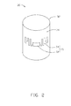
- FIG. 2 is a schematic view of a capacitor mounted on the PCB in FIG.1 .
- FIG. 3 is a schematic view of an inductor mounted on the PCB in FIG.1 .
- FIG. 1 is an assembled view of a printed circuit board (PCB) 100 with RFID tags, according to an exemplary embodiment.
- the PCB 100 includes a base board 10, a plurality of electronic components, and at least one RFID tag 70.
- the plurality of electronic components includes a capacitor 30 and an inductor 50. Both of the capacitor 30 and the inductor 50 are mounted on a side of the base board 10, to receive alternating current (AC) or direct current (DC) from the base board 10.
- AC alternating current
- DC direct current
- the capacitor 30 includes a capsule 32 made of metal or plastic.
- the capsule 32 is a cylinder, and includes a peripheral wall 34.
- the inductor 50 includes a shell 52 made of metal or plastic.
- the shell 52 is cube-shaped, and includes a top wall 54.
- the RFID tag 70 is a passive electronic component, and works at frequencies of about 125kHz, 133kHz, 13.56MHz, 27.12MHz, 433MHz, 902-928MHz, 2.45GHz, or 5.8GHz, for example.
- the RFID tag 70 is attached to the plurality of electronic components.
- the RFID tag 70 can be adhered to the peripheral wall 34 of the capacitor 30 via adhesive.
- the RFID tag 70 can be bonded on the top wall 54 of the inductor 50 using known processes. Because the RFID 70 is a passive component, it will not electronically interfere with the plurality of electronic components.
- the RFID tag 70 includes a microchip 72 and an induction coil 74 electronically connected to the microchip 72.
- the induction coil 74 inducts a magnetic field generated by the alternating current of the PCB 100, and thus outputs a driving current to turn on the microchip 72.
- the microchip 72 does not need other power sources.
- the microchip 72 stores predetermined identification information of the PCB 100 such as name, production date, type, and other related information.
- the RFID tag 70 communicates with a RFID reader (not shown) via the induction coil 74, to send the predetermined identification information to the RFID reader.
- the PCB 100 can be managed and tracked.
- the RFID tag 70 is mounted on the plurality of electronic components, a clear space on the base board 10 is not needed. Thus, design and manufacture of the PCB 100 is simplified and reduces costs.
- the RFID tag 70 can be mounted on other suitable locations of the capacitor 30 and the inductor 50 or other permanently mounted components with suitable surfaces.
- the plurality of electronic components can further include other elements, such as connectors, for example.
- the RFID tag 70 is mounted on one or more of the plurality of electronic components which are permanently mounted on the base board 10. Thus, this is very convenient for users in managing and tracking the PCB 100.
Landscapes
- Engineering & Computer Science (AREA)
- Microelectronics & Electronic Packaging (AREA)
- Physics & Mathematics (AREA)
- General Physics & Mathematics (AREA)
- Computer Hardware Design (AREA)
- Theoretical Computer Science (AREA)
- General Engineering & Computer Science (AREA)
- Manufacturing & Machinery (AREA)
- Quality & Reliability (AREA)
- Automation & Control Theory (AREA)
- Near-Field Transmission Systems (AREA)
- Credit Cards Or The Like (AREA)
Abstract
Description
- The disclosure generally relates to electronic components, and particularly relates to an electronic component and a printed circuit board with radio frequency identification (RFID) tags.
- To manage and track printed circuit boards (PCB), the PCBs are labeled with barcodes. However, such labeling requires a clear space on the PCB, making it difficult to further miniaturize the PCBs. Additionally, such labeling may be degraded by high temperatures or be worn away by handling.
- Therefore, there is room for improvement within the art.
- According to a first aspect of the disclosure, a printed circuit board (PCB) is provided. The PCB comprises a base board, a plurality of electronic components, and at least one radio frequency identification (RFID) tag, the plurality of electronic components are mounted on the base board, the at least one RFID tag is mounted on the plurality of electronic components, and the at least one RFID tag stores predetermined identification information of the PCB.
- According to a second aspect of the disclosure, a printed circuit board (PCB) is provided. The PCB comprises a base board, the base board integrates a plurality of electronic components, and at least one of the plurality of electronic components is provided with a radio frequency identification (RFID) tag, the RFID tag stores predetermined identification information of the PCB.
- According to a third aspect of the disclosure, an electronic component is provided. The electronic component comprises a radio frequency identification (RFID) tag, the RFID tag comprises a microchip and an induction coil electronically connected to the microchip; both the microchip and the induction coil are attached to an external wall of the electronic component.
- Many aspects of the printed circuit board and the electronic component can be better understood with reference to the following drawings. The components in the drawings are not necessarily drawn to scale, the emphasis instead being placed upon clearly illustrating the principles of the printed circuit board and the electronic component.
-
FIG. 1 is an assembled view of a printed circuit board (PCB) with RFID tags, according to an exemplary embodiment. -
FIG. 2 is a schematic view of a capacitor mounted on the PCB inFIG.1 . -
FIG. 3 is a schematic view of an inductor mounted on the PCB inFIG.1 . -
FIG. 1 is an assembled view of a printed circuit board (PCB) 100 with RFID tags, according to an exemplary embodiment. The PCB 100 includes abase board 10, a plurality of electronic components, and at least oneRFID tag 70. In one exemplary embodiment, the plurality of electronic components includes acapacitor 30 and aninductor 50. Both of thecapacitor 30 and theinductor 50 are mounted on a side of thebase board 10, to receive alternating current (AC) or direct current (DC) from thebase board 10. - In
FIG. 2 , thecapacitor 30 includes acapsule 32 made of metal or plastic. In one exemplary embodiment, thecapsule 32 is a cylinder, and includes aperipheral wall 34. - In
FIG. 3 , theinductor 50 includes ashell 52 made of metal or plastic. In one exemplary embodiment, theshell 52 is cube-shaped, and includes atop wall 54. - The
RFID tag 70 is a passive electronic component, and works at frequencies of about 125kHz, 133kHz, 13.56MHz, 27.12MHz, 433MHz, 902-928MHz, 2.45GHz, or 5.8GHz, for example. TheRFID tag 70 is attached to the plurality of electronic components. For example, theRFID tag 70 can be adhered to theperipheral wall 34 of thecapacitor 30 via adhesive. For another example, theRFID tag 70 can be bonded on thetop wall 54 of theinductor 50 using known processes. Because theRFID 70 is a passive component, it will not electronically interfere with the plurality of electronic components. - The
RFID tag 70 includes amicrochip 72 and aninduction coil 74 electronically connected to themicrochip 72. Theinduction coil 74 inducts a magnetic field generated by the alternating current of thePCB 100, and thus outputs a driving current to turn on themicrochip 72. Thus, themicrochip 72 does not need other power sources. Themicrochip 72 stores predetermined identification information of thePCB 100 such as name, production date, type, and other related information. TheRFID tag 70 communicates with a RFID reader (not shown) via theinduction coil 74, to send the predetermined identification information to the RFID reader. Thus, the PCB 100 can be managed and tracked. - Since the
RFID tag 70 is mounted on the plurality of electronic components, a clear space on thebase board 10 is not needed. Thus, design and manufacture of thePCB 100 is simplified and reduces costs. - In other exemplary embodiments, the
RFID tag 70 can be mounted on other suitable locations of thecapacitor 30 and theinductor 50 or other permanently mounted components with suitable surfaces. - In other exemplary embodiments, the plurality of electronic components can further include other elements, such as connectors, for example.
- In summary, the
RFID tag 70 is mounted on one or more of the plurality of electronic components which are permanently mounted on thebase board 10. Thus, this is very convenient for users in managing and tracking thePCB 100. - It is to be understood that even though numerous characteristics and advantages of the present embodiments have been set forth in the foregoing description, together with details of the structures and functions of the embodiments, the disclosure is illustrative only, and changes may be made in detail, especially in matters of shape, size, and arrangement of parts within the principles of the disclosure to the full extent indicated by the broad general meaning of the terms in which the appended claims are expressed.
Claims (14)
- A printed circuit board (PCB), comprises a base board, a plurality of electronic components, and at least one radio frequency identification (RFID) tag, the plurality of electronic components are mounted on the base board, the at least one RFID tag is mounted on the plurality of electronic components, and the at least one RFID tag stores predetermined identification information of the PCB.
- The PCB as claimed in claim 1, characterized in that: the plurality of electronic components comprises a capacitor, the at least one RFID tag is mounted on the capacitor.
- The PCB as claimed in claim 2, characterized in that: the capacitor has a peripheral wall, and the at least one RFID tag is adhered to the peripheral wall via adhesive.
- The PCB as claimed in claim 1, 2 or 3, characterized in that: the plurality of electronic components comprises an inductor, the at least one RFID tag is attached to the inductor.
- The PCB as claimed in claim 4, characterized in that: the inductor comprises a shell having a top wall, and the at least one RFID tag is bonded on the top wall.
- The PCB as claimed in any preceding claim, characterized in that: the least one RFID tag is a passive electronic component.
- The PCB as claimed in claim 6, characterized in that: the least one RFID tag comprises a microchip and an induction coil electronically connected to the microchip, the induction coil inducts a magnetic field generated by the base board, and outputs a driving current to turn on the microchip.
- The PCB as claimed in claim 7, characterized in that: the predetermined identification information is stored in the microchip.
- A printed circuit board (PCB), comprises a base board, the base board integrates a plurality of electronic components, and at least one of the plurality of electronic components is provided with a radio frequency identification (RFID) tag, the RFID tag stores predetermined identification information of the PCB.
- The PCB as claimed in claim 9, characterized in that: the plurality of electronic components comprises a capacitor, the at least one RFID tag is attached to the capacitor.
- The PCB as claimed in claim 9 or 10, characterized in that: the plurality of electronic components comprises an inductor, the at least one RFID tag is mounted on the inductor.
- An electronic component, comprises a radio frequency identification (RFID) tag, the RFID tag comprises a microchip and an induction coil electronically connected to the microchip; both the microchip and the induction coil are attached to an external wall of the electronic component.
- The electronic component as claimed in claim 12, characterized in that: the electronic component is a capacitor having a peripheral wall, and the RFID tag is adhered to the peripheral wall via adhesive.
- The electronic component as claimed in claim 12 or 13, characterized in that: the electronic component is an inductor having a top wall, and the RFID tag is bonded on the top wall.
Applications Claiming Priority (1)
| Application Number | Priority Date | Filing Date | Title |
|---|---|---|---|
| CN201220745041XU CN203167431U (en) | 2012-12-29 | 2012-12-29 | Electronic components and circuit boards with radio frequency tags |
Publications (1)
| Publication Number | Publication Date |
|---|---|
| EP2750487A1 true EP2750487A1 (en) | 2014-07-02 |
Family
ID=49028578
Family Applications (1)
| Application Number | Title | Priority Date | Filing Date |
|---|---|---|---|
| EP13185597.5A Withdrawn EP2750487A1 (en) | 2012-12-29 | 2013-09-23 | Electronic component and printed circuit board with RFID tag |
Country Status (5)
| Country | Link |
|---|---|
| US (1) | US8905319B2 (en) |
| EP (1) | EP2750487A1 (en) |
| KR (1) | KR20140004232U (en) |
| CN (1) | CN203167431U (en) |
| TW (1) | TWM492028U (en) |
Families Citing this family (1)
| Publication number | Priority date | Publication date | Assignee | Title |
|---|---|---|---|---|
| CN111076361A (en) * | 2019-12-11 | 2020-04-28 | 珠海格力电器股份有限公司 | Fan blade fault detection device and method, air conditioner external unit and air conditioner unit |
Citations (3)
| Publication number | Priority date | Publication date | Assignee | Title |
|---|---|---|---|---|
| US20050146347A1 (en) * | 2003-12-30 | 2005-07-07 | Yan Yevmenenko | Techniques for controlling movement of a circuit board module along card cage slot |
| US20050179549A1 (en) * | 2004-02-12 | 2005-08-18 | Fuji Photo Film Co., Ltd. | Electronic tag, system and method for selecting component |
| US20050253726A1 (en) * | 2004-05-14 | 2005-11-17 | Denso Corporation | Electronic unit having identification information thereof |
Family Cites Families (7)
| Publication number | Priority date | Publication date | Assignee | Title |
|---|---|---|---|---|
| DE60135100D1 (en) * | 2000-03-24 | 2008-09-11 | Cymbet Corp | E WITH ULTRA-THIN ELECTROLYTES |
| MX2009000087A (en) * | 2006-06-21 | 2009-03-20 | Neology Inc | Systems and methods for interrogator multiple radio frequency identification enabled documents. |
| US8322624B2 (en) * | 2007-04-10 | 2012-12-04 | Feinics Amatech Teoranta | Smart card with switchable matching antenna |
| US9304555B2 (en) * | 2007-09-12 | 2016-04-05 | Devicefidelity, Inc. | Magnetically coupling radio frequency antennas |
| WO2012144482A1 (en) * | 2011-04-18 | 2012-10-26 | 株式会社村田製作所 | Antenna device and communication terminal device |
| TWI488367B (en) * | 2011-11-15 | 2015-06-11 | Ind Tech Res Inst | Rfid tag antenna |
| WO2013094667A1 (en) * | 2011-12-22 | 2013-06-27 | 株式会社村田製作所 | Magnetic antenna, antenna device, and electronic equipment |
-
2012
- 2012-12-29 CN CN201220745041XU patent/CN203167431U/en not_active Expired - Fee Related
-
2013
- 2013-01-14 TW TW102200761U patent/TWM492028U/en not_active IP Right Cessation
- 2013-06-14 KR KR2020130004824U patent/KR20140004232U/en not_active Withdrawn
- 2013-08-23 US US13/974,165 patent/US8905319B2/en not_active Expired - Fee Related
- 2013-09-23 EP EP13185597.5A patent/EP2750487A1/en not_active Withdrawn
Patent Citations (3)
| Publication number | Priority date | Publication date | Assignee | Title |
|---|---|---|---|---|
| US20050146347A1 (en) * | 2003-12-30 | 2005-07-07 | Yan Yevmenenko | Techniques for controlling movement of a circuit board module along card cage slot |
| US20050179549A1 (en) * | 2004-02-12 | 2005-08-18 | Fuji Photo Film Co., Ltd. | Electronic tag, system and method for selecting component |
| US20050253726A1 (en) * | 2004-05-14 | 2005-11-17 | Denso Corporation | Electronic unit having identification information thereof |
Also Published As
| Publication number | Publication date |
|---|---|
| CN203167431U (en) | 2013-08-28 |
| KR20140004232U (en) | 2014-07-09 |
| US20140183267A1 (en) | 2014-07-03 |
| US8905319B2 (en) | 2014-12-09 |
| TWM492028U (en) | 2014-12-11 |
Similar Documents
| Publication | Publication Date | Title |
|---|---|---|
| US10303993B2 (en) | Wireless identification tag, electronic product PCB having same, and system for managing electronic products | |
| CN104521063B (en) | Plug-in connector housing with RFID transponder | |
| US20080204238A1 (en) | Method to RFID enable electronic devices | |
| JP2005323019A (en) | Booster antenna for rfid tag | |
| CN103020673A (en) | Article positioning system and method of RFID (Radio Frequency Identification) tag | |
| CN103534876B (en) | Peripheral type dipole antenna configuration and the PCB including this structure | |
| JP4736881B2 (en) | Storage management system, worker terminal constituting the system, storage management method, and storage management program | |
| WO2006001576A1 (en) | Eyelet for a radio frequency identification | |
| CN206532876U (en) | Antenna based on coil-type | |
| US20140117095A1 (en) | Tag integrated circuit module apparatus and method of fabricating tag integrated circuit module apparatus | |
| US8905319B2 (en) | Electronic component and printed circuit board with RFID tag | |
| US9704001B2 (en) | File searching system and file searching method thereof | |
| CN103500353A (en) | An embedded anti-metal UHF RFID tag | |
| US20150186686A1 (en) | Reader and information processing system employing same | |
| KR20160017588A (en) | Electronic shelf label tag with nfc function | |
| CN105184353B (en) | Miniaturized anti-metal RFID electronic tag with novel structure | |
| US20090128291A1 (en) | Method and apparatus of rfid communication during device assembly | |
| CN208188835U (en) | Interaction book and its interactive system with radio electronic label | |
| KR100627163B1 (en) | Eyelet for RFID | |
| US9727766B2 (en) | Chip card reading arrangement | |
| KR20140031646A (en) | Rfid tag with the high endurance | |
| US20140339314A1 (en) | Rfid tag and package using same | |
| KR20150122040A (en) | Electronic shelf label tag with embeded nfc function | |
| CN205263851U (en) | Novel broadband RFID electronic tags of structure | |
| JP2012163363A (en) | Identification tag, identification tag set, frequency division type identification terminal, and identification method |
Legal Events
| Date | Code | Title | Description |
|---|---|---|---|
| 17P | Request for examination filed |
Effective date: 20130923 |
|
| AK | Designated contracting states |
Kind code of ref document: A1 Designated state(s): AL AT BE BG CH CY CZ DE DK EE ES FI FR GB GR HR HU IE IS IT LI LT LU LV MC MK MT NL NO PL PT RO RS SE SI SK SM TR |
|
| AX | Request for extension of the european patent |
Extension state: BA ME |
|
| PUAI | Public reference made under article 153(3) epc to a published international application that has entered the european phase |
Free format text: ORIGINAL CODE: 0009012 |
|
| R17P | Request for examination filed (corrected) |
Effective date: 20141224 |
|
| RBV | Designated contracting states (corrected) |
Designated state(s): AL AT BE BG CH CY CZ DE DK EE ES FI FR GB GR HR HU IE IS IT LI LT LU LV MC MK MT NL NO PL PT RO RS SE SI SK SM TR |
|
| STAA | Information on the status of an ep patent application or granted ep patent |
Free format text: STATUS: THE APPLICATION IS DEEMED TO BE WITHDRAWN |
|
| 18D | Application deemed to be withdrawn |
Effective date: 20170401 |