EP2750470A1 - Methods and system for transmitting data between television receivers - Google Patents
Methods and system for transmitting data between television receivers Download PDFInfo
- Publication number
- EP2750470A1 EP2750470A1 EP13199608.4A EP13199608A EP2750470A1 EP 2750470 A1 EP2750470 A1 EP 2750470A1 EP 13199608 A EP13199608 A EP 13199608A EP 2750470 A1 EP2750470 A1 EP 2750470A1
- Authority
- EP
- European Patent Office
- Prior art keywords
- data
- television receiver
- wireless network
- bridge circuit
- wireless
- Prior art date
- Legal status (The legal status is an assumption and is not a legal conclusion. Google has not performed a legal analysis and makes no representation as to the accuracy of the status listed.)
- Granted
Links
Images



Classifications
-
- H—ELECTRICITY
- H04—ELECTRIC COMMUNICATION TECHNIQUE
- H04N—PICTORIAL COMMUNICATION, e.g. TELEVISION
- H04N21/00—Selective content distribution, e.g. interactive television or video on demand [VOD]
- H04N21/40—Client devices specifically adapted for the reception of or interaction with content, e.g. set-top-box [STB]; Operations thereof
- H04N21/43—Processing of content or additional data, e.g. demultiplexing additional data from a digital video stream; Elementary client operations, e.g. monitoring of home network or synchronising decoder's clock; Client middleware
- H04N21/436—Interfacing a local distribution network, e.g. communicating with another STB or one or more peripheral devices inside the home
- H04N21/4363—Adapting the video stream to a specific local network, e.g. a Bluetooth® network
- H04N21/43637—Adapting the video stream to a specific local network, e.g. a Bluetooth® network involving a wireless protocol, e.g. Bluetooth®, RF or wireless LAN [IEEE 802.11]
-
- H—ELECTRICITY
- H04—ELECTRIC COMMUNICATION TECHNIQUE
- H04W—WIRELESS COMMUNICATION NETWORKS
- H04W28/00—Network traffic management; Network resource management
- H04W28/16—Central resource management; Negotiation of resources or communication parameters, e.g. negotiating bandwidth or QoS [Quality of Service]
- H04W28/26—Resource reservation
-
- H—ELECTRICITY
- H04—ELECTRIC COMMUNICATION TECHNIQUE
- H04W—WIRELESS COMMUNICATION NETWORKS
- H04W92/00—Interfaces specially adapted for wireless communication networks
- H04W92/16—Interfaces between hierarchically similar devices
- H04W92/18—Interfaces between hierarchically similar devices between terminal devices
Definitions
- the present invention relates to methods of transmitting data between television receivers and to a related system.
- the present disclosure relates to the field of wireless networks.
- the present disclosure relates more particularly to the field of wireless networks implemented in conjunction with television receivers.
- Embodiments implement a WIFI Video Bridge circuit in Quality of Service.
- a wireless bridge circuit can be used to allow one electronic device to wirelessly communicate with another electronic device by implementing a wireless network connecting to devices. Data can be passed between the two electronic devices wirelessly.
- Wireless bridge circuits have limited data bandwidths. In some cases, multiple types of data are sent over the wireless network between the two electronic devices. One type of data can be more important than other type of data. When the bridge circuit's bandwidth is full, one type of data may need to be given priority over another type of data.
- a method of transmitting data between television receivers comprising:
- the method may further comprise:
- the method may comprise connecting the wireless bridge circuit to the internet through the first television receiver.
- the first data type may be video data.
- the data received by the first television receiver from the media content provider may be transmitted over the first wireless network and data received by the bridge circuit from the Internet is transmitted over the second wireless network.
- the first wireless network may have a first serial set identifier and the second wireless network may have a second serial set identifier.
- the method may comprise providing more bandwidth of the wireless bridge circuit for the first wireless network than for the second wireless network.
- the media content provider may be a television service provider and the media content includes video content.
- the method may comprise providing the video content from the second television receiver to a display coupled to the second television receiver.
- a system for transmitting data between television receivers comprising:
- the second television receiver may be configured to receive video content from a media content provider, the first type of data including video content.
- the second television receiver may be configured to send the video content to the first television receiver over the first wireless network.
- the first television receiver may be configured to receive the first and the second types of data from a wireless antenna coupled to the first television receiver.
- a method of transmitting data between television receivers comprising:
- the method may comprise giving higher wireless bridge circuit bandwidth priority to the first wireless network than to the second wireless network.
- One embodiment is a method for wirelessly transmitting data from a bridge circuit having limited bandwidth while giving priority to one type of data over another.
- a wireless bridge circuit wirelessly transmits data to an electronic device.
- the wireless bridge circuit transmits data to the device on two separate wireless networks.
- One of the wireless networks is reserved for data of a first type while the other wireless network is reserved for data of second type.
- the first type of data is more sensitive to delay or disruption than the second type.
- the wireless bridge circuit provides a higher priority to the wireless network transmitting the first data type. In this way, when the wireless bridge circuit is using most of its bandwidth, the first wireless network will be given bandwidth at the expense of the second wireless network so that transmission of the first data type is not interrupted.
- the wireless bridge circuit is connected to a first television receiver.
- the wireless bridge circuit transmits video content and other data from the first television receiver to a second television receiver.
- the second television receiver displays the video content on a display.
- the wireless bridge circuit transmits video content to the second television receiver on the first wireless network.
- the wireless bridge circuit transmits other types of data to the second television receiver on the second wireless network. Because the quality of a video program is greatly impacted by any delay in the transmission of the video data, the first wireless network is given bandwidth priority over the second wireless network.
- the television program data transmitted from the first television receiver will not be interrupted or delayed due to large amounts of other kinds of data being transmitted on the second wireless network.
- the quality of television programs and other types of video content will be preserved at the expense of other types of data.
- FIG. 1 is a block diagram of a media content delivery system 20 according to one embodiment.
- the media content delivery system 20 includes a first electronic device 22a.
- the electronic device 22a is coupled to a media content provider 24, a display 26a, and the Internet 28.
- the media content delivery system 20 further includes a second electronic device 22b coupled to a second display 26b.
- the electronic device 22a receives media content or other data from a media content provider 24.
- the electronic device 22a also receives Internet data from the Internet 28.
- the electronic device 22a can display images or video received from the media content provider 24 or the Internet 28 on the display 26a.
- Electronic device 22a is configured to wirelessly transmit data from the media content provider 24 and the Internet 28 to the electronic device 22b.
- Electronic device 22b can display video, images, or other data received from the electronic device 22a on the display 26b.
- Many types of data such as video data, image data, text data, email data, software data, and other types of data can be transmitted from the electronic device 22a to the electronic device 22b.
- the electronic device 22a has limited data bandwidth.
- the electronic device 22a cannot transmit data beyond a certain data rate. Therefore, if the electronic device 22a is transmitting a high volume of data to the electronic device 22b, some data can be delayed or interrupted. Some kinds of data can be delayed or interrupted without adversely affecting the electronic device 22b or the experience of the user using the electronic device 22b. Other kinds of data are particularly sensitive to delay or interruption. Such delays or interruptions can adversely affect the function of the electronic device 22b or the experience of the user using the electronic device 22b.
- electronic device 22a is configured to give bandwidth priority to certain kinds of sensitive data at the expense of other kinds of less sensitive data.
- Wirelessly transmitted data is commonly sent according to packet-switched protocols. It is possible to tag each data packet sent between the electronic devices 22a, 22b with priority indicators. In this case electronic devices 22a, 22b will sort each packet to determine the priority of the individual packets so that packets with a higher priority tag can be given bandwidth priority over packets with lower priority tags. However, this can require more processing resources to tag each data packet in this way. This can both increase the expense of the electronic devices 22a, 22b and can also introduce other delays in interruptions.
- electronic device 22a is configured to transmit data to the electronic device 22b on two different wireless networks.
- Electronic devices 22a, 22b are, therefore, wirelessly connected to each other on two separate wireless networks.
- the first wireless network can be reserved for sending data types having a higher priority.
- the second wireless network can be reserved for sending data types having a lower priority.
- Electronic devices 22a, 22b are configured to give bandwidth priority to the first wireless network. If a high data volume is being transmitted between the electronic devices 22a, 22b and the data rate bandwidth is nearing maximum capacity, electronic devices 22a, 22b automatically sacrifice the bandwidth of the second wireless network in favor of the first wireless network. If data is being transmitted across first and second wireless networks, the second wireless network is only given the bandwidth remaining after sufficient bandwidth has been allocated to ensure that the first wireless network can handle the high priority data without introducing delays or interruptions.
- Wireless networks are typically identified by a unique serial set identifier (SSID) or other type of identifier identifying the wireless network.
- SSID unique serial set identifier
- Each data packet is typically tagged to identify the SSID of the wireless network over which it is being transmitted.
- the electronic devices 22a, 22b are capable of establishing two separate wireless networks each with a unique SSID.
- the data packets can be transmitted over the two wireless networks without additionally tagging each data packet with a priority tag. Instead the electronic devices 22a, 22b on allocated bandwidth priority to one wireless network over the other. Thus there is no extra tagging of the data packets to indicate priority. This allows data to be transmitted from the electronic device 22a to the electronic device 22b in a very efficient manner without adding additional data which uses further bandwidth.
- the electronic device 22a may receive data both from the Internet 28 and the media content provider 24, and provides this data to the electronic device 22b.
- data types such as video streaming or high priority system update data can be transmitted over the higher priority wireless network, while data such as text messages, email, or low priority software updates can be sent over the lower priority second wireless network. Because the first wireless network has bandwidth priority over the second wireless network, the higher priority data will not be delayed or interrupted due to the lower priority data.
- the electronic devices 22a, 22b may be television receivers.
- the television receiver 22a transits media content data such as television programs to the television receiver 22b.
- the television receiver 22b receives the media content and displays the media content on the display 26b. Because the quality of television viewing decreases sharply if there are delays or interruptions in a television program while it is being displayed, video data from the television receiver 22a is sent over the high priority first wireless network. Other data such as programming guide data or other kinds of lower priority data can be sent over the second wireless network. In this way a user using a television receiver 22b can view video content without disruption due to a high volume of lower priority data being transmitted.
- electronic devices 22a, 22b may include handheld devices such as smart phones, gaming devices, tablets, or other types of handheld devices.
- Electronic devices 22a, 22b to be can further include laptop computers, desktop computers, televisions, and other devices.
- Figure 1 depicts the electronic device 22a as a single device transmitting data to the electronic device 22b.
- the electronic device 22a may be coupled to a first wireless bridge circuit.
- the electronic device 22a provides data to the first wireless bridge circuit which transmits the data to the electronic device 22b.
- the electronic device 22b may be coupled to a second wireless bridge circuit which receives data from the first wireless bridge circuit.
- the second wireless bridge circuit also sends data to the first wireless bridge circuit.
- data from the first electronic device 22a can be wirelessly transmitted to the electronic device 22b by utilizing respective wireless bridge circuits coupled to electronic devices 22a, 22b.
- electronic device 22a can have a first wireless bridge circuit incorporated therewith such that the first wireless bridge circuit is part of the electronic device 22a.
- electronic device 22b can have a second wireless bridge circuit incorporated there with such that the second wireless bridge circuit is part of the electronic device 22a.
- Figure 1 shows electronic device 22a the connected to media content provider 24, the Internet 28, and the display 26a.
- the electronic device 22a is connected to more or fewer devices or data sources.
- the electronic device 22b may be connected to more devices than just the display 26b.
- Electronic device 22b may also be connected to other devices or data sources.
- FIG. 2 illustrates a media content distribution system 20 according to one embodiment.
- the media content distribution system includes a satellite transponder 24, the satellite dish 29, and a first television receiver 22a coupled to the satellite dish 29.
- the media content distribution system 20 further includes a wireless bridge circuit 30 and a television 26a coupled to the first television receiver 22a.
- a second television receiver 22b is wirelessly coupled to the first television receiver 22a through the wireless bridge circuit 30.
- the second television 26b is coupled to the television receiver 22b.
- a first user 32a operates the first television receiver 22a.
- a second user 32b operates the second television receiver 22b.
- the satellite transponder 24 provides media content data to the satellite dish 29.
- the media content data includes television program data carried on various television channels, identification and encoding data, program guide data, and many other kinds of data.
- the television receiver 22a receives the media content data from the satellite dish 29.
- the television receiver 22a can tune into a television channel to display television programs on the television 26a.
- the television receiver 22a also can receive other kinds of video content from the satellite dish 29 which can be displayed on the television 26a.
- the first television receiver 22a wirelessly transmits media content data to the second television receiver 22b through the wireless bridge circuit 30.
- the user 32b uses a remote control to operate the television receiver 22b.
- the television receiver 22b is operated by the user in a manner similar to how the user 32a operates the television receiver 22a.
- the user 32b can view a programming guide on the television 26b and can select a media content channel to view on the television 26b.
- the programming guide data is received wirelessly by the second television receiver 22b from the first television receiver 22a.
- one or both of the second television receiver 22b and the television 26b can be used to download information from the Internet 28.
- some televisions allow a user to type emails and to surf the web by connecting the television to the Internet.
- Television 26b can be connected to the television receiver 22b by an ethernet cable in addition to a video output cable which commonly connects a television receiver to a television.
- the television receiver 22b can connect to the Internet 28 via the wireless bridge circuit 30.
- the wireless bridge circuit 30 can therefore transmit Internet data to the television receiver 22b in addition to the media content data which is transmitted to the television receiver 22b.
- the wireless bridge circuit 30 can reach its maximum bit rate bandwidth. If the data is not managed properly, it is possible that the television program can be delayed or interrupted. This can result in unwanted pixilation of the television program, a decrease in resolution of the television program, frame rate decrease, freezing of a frame, or an otherwise delayed or interrupted viewing experience. This will cause a decrease in the quality of the television viewing experience for the user 32b.
- a user may wish to watch a football game live on display 26b over the wireless connection.
- another user in the home wishes to download a large software game or a movie.
- the large software game will take a large amount of data bandwidth that would slow the entire system down if it were broadcast over the same network.
- the software game is broadcast out on the second network, not on the first network.
- the second network can only broadcast only when sufficient bandwidth becomes available that is not being used by the first network.
- the first network enters a mode in which lower data rates are being broadcast, such as during an instant replay or while announcers are talking and the football play is not active, this will provide more bandwidth for a brief period of time for the other type of data, in this case a software game instead of a live video feed. Then, when the first type of data takes up more bandwidth to send correctly, the bandwidth of the second wireless network will be reduced accordingly.
- the wireless bridge circuit 30 can implement two wireless networks: a first wireless network is for transmitting high-priority data, while a second wireless network is for transmitting lower priority data. If the maximum bandwidth of the wireless bridge circuit 30 is approached, priority is given to the first wireless network. In this way the video content displayed on the television 26b will not be delayed or interrupted.
- all data from the media content provider is transmitted over the first wireless network, while all data from the Internet 28 is transmitted over the second wireless network.
- only video data from the satellite transponder 24 is transmitted over the first wireless network.
- video data from either the Internet or from the satellite transponder 24 are transmitted over the first wireless network, while all other types of data are transmitted over the second wireless network.
- video data from either the Internet or from the satellite transponder 24 are transmitted over the first wireless network, while all other types of data are transmitted over the second wireless network.
- One type of data can be transmitted over the first wireless network while another type of data can be transmitted over the second wireless network.
- the media content distribution system 20 can be a cable television media content distribution system.
- the television receiver 22a can receive media content from a cable television provider.
- Television receiver 22a can also receive Internet data from the cable television provider.
- the second television receiver 22b can include a second wireless bridge circuit incorporated therein to receive the wireless transmissions from the first television receiver 22a.
- the second television receiver 22b can be coupled to a second wireless bridge circuit which receives the transmissions from the first television receiver 22a.
- two wireless networks are set up between the wireless bridge circuit 30 and a second wireless bridge circuit 30b coupled to the second television receiver 22b.
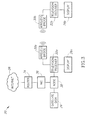
- FIG 3 illustrates a media content distribution system 20 according to one embodiment.
- the media content distribution system 20 of Figure 3 includes a television receiver 22a which receives media content data from a satellite dish 29 and Internet data from the Internet 28.
- the satellite dish 29 is coupled to a node 38 which is further coupled to the television receiver 22a.
- the media content data from the satellite dish 29 is passed to the node 38 and from the node to the television receiver 22a.
- Internet data 28 is received by a router 34.
- the router 34 passes the Internet data to a headend interface converter (HIC) 36.
- the head end interface converter supplies the Internet data to the node 38 which supplies the Internet data to the television receiver 22a.
- HIC headend interface converter
- the television receiver 22a transmits data to a second television receiver 22b.
- the television receiver 22a supplies data to a Wi-Fi bridge circuit 30a which wirelessly transmits the data to a second Wi-Fi bridge circuit 30b coupled to the second television receiver 22b.
- the television receiver 22a therefore transmits media content data received from the satellite dish 29 and Internet data received from the Internet 28 to the second television receiver 22b.
- Two wireless networks are therefore established between the first and second wireless bridge circuits 30a and 30b.
- Higher priority data such as video content data is transmitted on a first wireless network while lower priority data is transmitted on the second wireless network.
- Higher bandwidth priority is given to the first wireless network than the second wireless network. If the maximum bandwidth of the Wi-Fi bridge circuits 30a and 30b is approached, the first wireless network has priority so the higher priority video content data will not be delayed or interrupted in favor of the lower priority data on the second wireless network.
- the types of data sent on the respective wireless networks can be determined according to other criteria.
- FIG 4 is a block diagram of a media content distribution system 20 according to an embodiment.
- the television receiver 22a receives media content from a satellite dish 29.
- the television receiver 22a provides media content data to a wireless bridge circuit 30 which transmits the media content data to a second television receiver 22b as described previously.
- a wireless bridge circuit 30 is also connected to the Internet 28.
- the television receiver 22b can connect to the Internet 28 through the wireless bridge circuit 30 without going through the television receiver 22a.
- the television receiver 22b is coupled to a display 26b by a media output connection 39 and an Internet connection 40.
- the media output connection 39 is, for example, an HDMI cable, a coaxial cable, or any other suitable media output connection by which video content can be provided to the display 26b.
- the Internet connection 40 is, for example, an ethernet cable, a coaxial cable, or any other suitable cable.
- the display 26b is connected to the television receiver 22b by only a single connection.
- the wireless bridge circuit 30 transmits data to the television receiver 22b on two different wireless networks.
- the two different wireless networks have differing priority as described previously.
- the wireless bridge circuit 30 can supply high priority data.
- the wireless bridge circuit 30 can supply lower priority data.
- the first wireless network has higher bandwidth priority than the second wireless network. Thus higher priority data will not be interrupted due to a large volume of lower priority data.
- the first wireless network can have a first SSID while the second wireless network has a second SSID.
- the two wireless networks can be implemented in a different suitable way.
- FIG. 5 is a block diagram of a television receiver 22a according to one embodiment.
- the television receiver 22a includes main control circuitry 44.
- the main control circuitry 44 can include one or more circuits such as multiple integrated circuits implemented on one or more printed circuit boards.
- the control circuitry 44 is coupled to a media input 46.
- the media input 46 receives media content data from a media content provider such as a satellite or cable television provider.
- the control circuitry 44 is further coupled to ethernet circuitry 48.
- the ethernet circuitry 48 couples the control circuitry 44 to an Internet connection.
- the ethernet connection 48 can be a different type of connection which allows the control circuitry 44 to be connected to the Internet 28.
- the control circuitry 44 is further coupled to a remote control transceiver 50.
- the remote control transceiver 50 communicates with a remote control by which a user can control the television receiver 22a.
- the control circuitry 44 is further coupled to a media output 52 by which media data can be supplied to a display 26.
- media data For example, television programs received from a media content provider 24 can be output to the television 26 by the media output 52.
- the television receiver 22 further comprises a wireless bridge circuit 30.
- the wireless bridge circuit 30 is configured to transmit data wirelessly to another device.
- the control circuitry 44 supplies Internet data and media content data to the wireless bridge circuit 30 which then transmits the data to a second television receiver 22b as described previously.
- the wireless bridge circuit 30 can establish two wireless networks having differing levels of bandwidth priority. Higher priority data can be transmitted on the first wireless network. Lower priority data can be transmitted on the second wireless network.
- the second television receiver 22b can include generally similar components as those described in relation to the television receiver 22a.
- the second television receiver 22b can also include an ethernet port, control circuitry, a remote control transceiver, a wireless bridge circuit, and media output.
- the television receivers 22a, 22b can include many other components not described herein as understood by those of skill in the art.
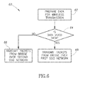
- Figure 6 is a flow diagram of a process 60 for transmitting data in a media content distribution system 20.
- data is prepared by a first television receiver 22a for wireless transmission.
- the data can be received from a media content provider and/or the Internet. Alternatively the data that is generated or stored locally in the first television receiver 22a.
- the television receiver 22a determines if the if the data is video data, or another type of high priority data. If the data is not video data or another kind of high priority data, the low priority data packets are transmitted from the bridge circuit 30a over a second SSID network. If the data is video data or another kind of high priority data, the wireless bridge circuit 30a transmits the high priority data packets over the wireless bridge circuit 30a via the first SSID network.
- the first SSID network has a higher bandwidth priority than the second SSID network. This helps to ensure that there is no delay or interruption in high priority data such as video data at a second television receiver 22b. In this way video data being viewed by user 32b will not be subject to a downgrade in resolution, a delay, interruption, a reduction in frame rates, or any other type of disruption.
Landscapes
- Engineering & Computer Science (AREA)
- Computer Networks & Wireless Communication (AREA)
- Multimedia (AREA)
- Signal Processing (AREA)
- Two-Way Televisions, Distribution Of Moving Picture Or The Like (AREA)
Abstract
Description
- The present invention relates to methods of transmitting data between television receivers and to a related system.
- The present disclosure relates to the field of wireless networks. The present disclosure relates more particularly to the field of wireless networks implemented in conjunction with television receivers. Embodiments implement a WIFI Video Bridge circuit in Quality of Service.
- A wireless bridge circuit can be used to allow one electronic device to wirelessly communicate with another electronic device by implementing a wireless network connecting to devices. Data can be passed between the two electronic devices wirelessly.
- Wireless bridge circuits have limited data bandwidths. In some cases, multiple types of data are sent over the wireless network between the two electronic devices. One type of data can be more important than other type of data. When the bridge circuit's bandwidth is full, one type of data may need to be given priority over another type of data.
- According to a first aspect of the present invention, there is provided a method of transmitting data between television receivers, comprising:
- receiving, in a first television receiver, media content from a media content provider; and
- transmitting the media content from the first television receiver to a second television receiver via a wireless bridge circuit, the transmitting including:
- transmitting a first data type from the wireless bridge circuit to the second television receiver over a first wireless network; and
- transmitting a second data type from the wireless bridge circuit to the second television receiver over a second wireless network.
- The method may further comprise:
- connecting the wireless bridge circuit to the Internet;
- receiving, in the wireless bridge circuit, internet data from the Internet; and
- transmitting the internet data from the wireless bridge circuit to the second television receiver on the first or the second wireless network based in part on whether the internet data is of the first or second data type.
- The method may comprise connecting the wireless bridge circuit to the internet through the first television receiver.
- The first data type may be video data.
- The data received by the first television receiver from the media content provider may be transmitted over the first wireless network and data received by the bridge circuit from the Internet is transmitted over the second wireless network.
- The first wireless network may have a first serial set identifier and the second wireless network may have a second serial set identifier.
- The method may comprise providing more bandwidth of the wireless bridge circuit for the first wireless network than for the second wireless network.
- The media content provider may be a television service provider and the media content includes video content.
- The method may comprise providing the video content from the second television receiver to a display coupled to the second television receiver.
- According to a second aspect of the present invention, there is provided a system for transmitting data between television receivers, comprising:
- a first television receiver;
- a wireless bridge circuit; and
- a second television receiver coupled to the wireless bridge circuit and configured to send to the first television receiver, via the wireless bridge circuit, a first type of data on a first wireless network and a second type of data on a second wireless network.
- The second television receiver may be configured to receive video content from a media content provider, the first type of data including video content.
- The second television receiver may be configured to send the video content to the first television receiver over the first wireless network.
- The first television receiver may be configured to receive the first and the second types of data from a wireless antenna coupled to the first television receiver.
- According to a third aspect of the present invention, there is provided a method of transmitting data between television receivers, comprising:
- receiving, in a first television receiver, internet data from the internet;
- receiving, in the first television receiver, media data from a media content provider, the media data and the internet data being of either a first or a second data type;
- transmitting, via a wireless bridge circuit, the media data and the Internet data from the first television receiver to a second television receiver on either a first wireless network or a second wireless network, the first data type being transmitted over the first wireless network and the second data type being transmitted over the second wireless network.
- The method may comprise giving higher wireless bridge circuit bandwidth priority to the first wireless network than to the second wireless network.
- One embodiment is a method for wirelessly transmitting data from a bridge circuit having limited bandwidth while giving priority to one type of data over another. In one embodiment a wireless bridge circuit wirelessly transmits data to an electronic device. The wireless bridge circuit transmits data to the device on two separate wireless networks. One of the wireless networks is reserved for data of a first type while the other wireless network is reserved for data of second type. The first type of data is more sensitive to delay or disruption than the second type. The wireless bridge circuit provides a higher priority to the wireless network transmitting the first data type. In this way, when the wireless bridge circuit is using most of its bandwidth, the first wireless network will be given bandwidth at the expense of the second wireless network so that transmission of the first data type is not interrupted.
- In one embodiment the wireless bridge circuit is connected to a first television receiver. The wireless bridge circuit transmits video content and other data from the first television receiver to a second television receiver. The second television receiver displays the video content on a display. The wireless bridge circuit transmits video content to the second television receiver on the first wireless network. The wireless bridge circuit transmits other types of data to the second television receiver on the second wireless network. Because the quality of a video program is greatly impacted by any delay in the transmission of the video data, the first wireless network is given bandwidth priority over the second wireless network.
- Thus, if a user of the second television receiver is viewing a television program on the display, the television program data transmitted from the first television receiver will not be interrupted or delayed due to large amounts of other kinds of data being transmitted on the second wireless network. The quality of television programs and other types of video content will be preserved at the expense of other types of data.
- It will be appreciated that any features expressed herein as being provided "in one example" or "in an embodiment" or as being "preferable" may be provided in combination with any one or more other such features together with any one or more of the aspects of the present invention.
- Embodiments of the present invention will now be described by way of example with reference to the accompanying drawings, in which:
-
Figure 1 is an example of a block diagram of a media content delivery system according to one embodiment. -
Figure 2 illustrates an example of a home including wirelessly communicating set top boxes according to one embodiment. -
Figure 3 is an example of a block diagram of a media content delivery system according to one embodiment. -
Figure 4 is an example of a block diagram of a media content delivery system according to an embodiment. -
Figure 5 is an example of a block diagram of a television receiver according to one embodiment. -
Figure 6 is an example of a flowchart of a process for delivering data over multiple wireless networks. -
Figure 1 is a block diagram of a mediacontent delivery system 20 according to one embodiment. The mediacontent delivery system 20 includes a firstelectronic device 22a. Theelectronic device 22a is coupled to amedia content provider 24, adisplay 26a, and the Internet 28. The mediacontent delivery system 20 further includes a secondelectronic device 22b coupled to asecond display 26b. - The
electronic device 22a receives media content or other data from amedia content provider 24. Theelectronic device 22a also receives Internet data from theInternet 28. Theelectronic device 22a can display images or video received from themedia content provider 24 or theInternet 28 on thedisplay 26a. -
Electronic device 22a is configured to wirelessly transmit data from themedia content provider 24 and theInternet 28 to theelectronic device 22b.Electronic device 22b can display video, images, or other data received from theelectronic device 22a on thedisplay 26b. Many types of data such as video data, image data, text data, email data, software data, and other types of data can be transmitted from theelectronic device 22a to theelectronic device 22b. - The
electronic device 22a has limited data bandwidth. Theelectronic device 22a cannot transmit data beyond a certain data rate. Therefore, if theelectronic device 22a is transmitting a high volume of data to theelectronic device 22b, some data can be delayed or interrupted. Some kinds of data can be delayed or interrupted without adversely affecting theelectronic device 22b or the experience of the user using theelectronic device 22b. Other kinds of data are particularly sensitive to delay or interruption. Such delays or interruptions can adversely affect the function of theelectronic device 22b or the experience of the user using theelectronic device 22b. - To alleviate delays or interruptions that can adversely impact the function of the
electronic device 22b, and the experience of the user using theelectronic device 22b,electronic device 22a is configured to give bandwidth priority to certain kinds of sensitive data at the expense of other kinds of less sensitive data. Wirelessly transmitted data is commonly sent according to packet-switched protocols. It is possible to tag each data packet sent between theelectronic devices electronic devices electronic devices - Accordingly, in one embodiment,
electronic device 22a is configured to transmit data to theelectronic device 22b on two different wireless networks.Electronic devices -
Electronic devices electronic devices electronic devices - Wireless networks are typically identified by a unique serial set identifier (SSID) or other type of identifier identifying the wireless network. Each data packet is typically tagged to identify the SSID of the wireless network over which it is being transmitted. The
electronic devices electronic devices electronic device 22a to theelectronic device 22b in a very efficient manner without adding additional data which uses further bandwidth. - The
electronic device 22a may receive data both from theInternet 28 and themedia content provider 24, and provides this data to theelectronic device 22b. This can include numerous types of data. In one example data types such as video streaming or high priority system update data can be transmitted over the higher priority wireless network, while data such as text messages, email, or low priority software updates can be sent over the lower priority second wireless network. Because the first wireless network has bandwidth priority over the second wireless network, the higher priority data will not be delayed or interrupted due to the lower priority data. - The
electronic devices television receiver 22a transits media content data such as television programs to thetelevision receiver 22b. Thetelevision receiver 22b receives the media content and displays the media content on thedisplay 26b. Because the quality of television viewing decreases sharply if there are delays or interruptions in a television program while it is being displayed, video data from thetelevision receiver 22a is sent over the high priority first wireless network. Other data such as programming guide data or other kinds of lower priority data can be sent over the second wireless network. In this way a user using atelevision receiver 22b can view video content without disruption due to a high volume of lower priority data being transmitted. - Alternatively
electronic devices Electronic devices -
Figure 1 depicts theelectronic device 22a as a single device transmitting data to theelectronic device 22b. However, in practice theelectronic device 22a may be coupled to a first wireless bridge circuit. Theelectronic device 22a provides data to the first wireless bridge circuit which transmits the data to theelectronic device 22b. - Likewise, the
electronic device 22b may be coupled to a second wireless bridge circuit which receives data from the first wireless bridge circuit. The second wireless bridge circuit also sends data to the first wireless bridge circuit. In this way data from the firstelectronic device 22a can be wirelessly transmitted to theelectronic device 22b by utilizing respective wireless bridge circuits coupled toelectronic devices - Alternatively
electronic device 22a can have a first wireless bridge circuit incorporated therewith such that the first wireless bridge circuit is part of theelectronic device 22a. Likewise theelectronic device 22b can have a second wireless bridge circuit incorporated there with such that the second wireless bridge circuit is part of theelectronic device 22a. -
Figure 1 showselectronic device 22a the connected tomedia content provider 24, theInternet 28, and thedisplay 26a. However, this is given only by way of example. In some embodiments theelectronic device 22a is connected to more or fewer devices or data sources. Likewise, theelectronic device 22b may be connected to more devices than just thedisplay 26b.Electronic device 22b may also be connected to other devices or data sources. -
Figure 2 illustrates a mediacontent distribution system 20 according to one embodiment. The media content distribution system includes asatellite transponder 24, thesatellite dish 29, and afirst television receiver 22a coupled to thesatellite dish 29. The mediacontent distribution system 20 further includes awireless bridge circuit 30 and atelevision 26a coupled to thefirst television receiver 22a. Asecond television receiver 22b is wirelessly coupled to thefirst television receiver 22a through thewireless bridge circuit 30. Thesecond television 26b is coupled to thetelevision receiver 22b. A first user 32a operates thefirst television receiver 22a. Asecond user 32b operates thesecond television receiver 22b. - The
satellite transponder 24 provides media content data to thesatellite dish 29. The media content data includes television program data carried on various television channels, identification and encoding data, program guide data, and many other kinds of data. Thetelevision receiver 22a receives the media content data from thesatellite dish 29. Thetelevision receiver 22a can tune into a television channel to display television programs on thetelevision 26a. Thetelevision receiver 22a also can receive other kinds of video content from thesatellite dish 29 which can be displayed on thetelevision 26a. - The
first television receiver 22a wirelessly transmits media content data to thesecond television receiver 22b through thewireless bridge circuit 30. Theuser 32b uses a remote control to operate thetelevision receiver 22b. Thetelevision receiver 22b is operated by the user in a manner similar to how the user 32a operates thetelevision receiver 22a. Theuser 32b can view a programming guide on thetelevision 26b and can select a media content channel to view on thetelevision 26b. The programming guide data is received wirelessly by thesecond television receiver 22b from thefirst television receiver 22a. - In one embodiment, one or both of the
second television receiver 22b and thetelevision 26b can be used to download information from theInternet 28. For example, some televisions allow a user to type emails and to surf the web by connecting the television to the Internet.Television 26b can be connected to thetelevision receiver 22b by an ethernet cable in addition to a video output cable which commonly connects a television receiver to a television. Thetelevision receiver 22b can connect to theInternet 28 via thewireless bridge circuit 30. Thewireless bridge circuit 30 can therefore transmit Internet data to thetelevision receiver 22b in addition to the media content data which is transmitted to thetelevision receiver 22b. - If the
user 32b is watching the video program on thetelevision 26b while also downloading data from theInternet 28 or from themedia content provider 24, it is possible that thewireless bridge circuit 30 can reach its maximum bit rate bandwidth. If the data is not managed properly, it is possible that the television program can be delayed or interrupted. This can result in unwanted pixilation of the television program, a decrease in resolution of the television program, frame rate decrease, freezing of a frame, or an otherwise delayed or interrupted viewing experience. This will cause a decrease in the quality of the television viewing experience for theuser 32b. - On the other hand a delay in other types of data such as programming guide data, web surfing data, email data, and many other kinds of data will not result in a significant disturbance to the
user 32b. Accordingly, high-priority types of data such as video data can be sent from thewireless bridge circuit 30 with a higher priority than other types of data. - To take a particular example, a user may wish to watch a football game live on
display 26b over the wireless connection. At the same time, another user in the home wishes to download a large software game or a movie. The large software game will take a large amount of data bandwidth that would slow the entire system down if it were broadcast over the same network. Thus, the software game is broadcast out on the second network, not on the first network. The second network can only broadcast only when sufficient bandwidth becomes available that is not being used by the first network. If the first network enters a mode in which lower data rates are being broadcast, such as during an instant replay or while announcers are talking and the football play is not active, this will provide more bandwidth for a brief period of time for the other type of data, in this case a software game instead of a live video feed. Then, when the first type of data takes up more bandwidth to send correctly, the bandwidth of the second wireless network will be reduced accordingly. - As described previously, the
wireless bridge circuit 30 can implement two wireless networks: a first wireless network is for transmitting high-priority data, while a second wireless network is for transmitting lower priority data. If the maximum bandwidth of thewireless bridge circuit 30 is approached, priority is given to the first wireless network. In this way the video content displayed on thetelevision 26b will not be delayed or interrupted. - In one example all data from the media content provider is transmitted over the first wireless network, while all data from the
Internet 28 is transmitted over the second wireless network. Alternatively, only video data from thesatellite transponder 24 is transmitted over the first wireless network. - In one embodiment video data from either the Internet or from the
satellite transponder 24 are transmitted over the first wireless network, while all other types of data are transmitted over the second wireless network. Many other configurations are possible in which one type of data can be transmitted over the first wireless network while another type of data can be transmitted over the second wireless network. - While
Figure 2 has depicted a satellite mediacontent distribution system 20, other types of media content distribution systems are possible. For example the mediacontent distribution system 20 can be a cable television media content distribution system. Thetelevision receiver 22a can receive media content from a cable television provider.Television receiver 22a can also receive Internet data from the cable television provider. - The
second television receiver 22b can include a second wireless bridge circuit incorporated therein to receive the wireless transmissions from thefirst television receiver 22a. Alternatively thesecond television receiver 22b can be coupled to a second wireless bridge circuit which receives the transmissions from thefirst television receiver 22a. Thus two wireless networks are set up between thewireless bridge circuit 30 and a secondwireless bridge circuit 30b coupled to thesecond television receiver 22b. -
Figure 3 illustrates a mediacontent distribution system 20 according to one embodiment. The mediacontent distribution system 20 ofFigure 3 includes atelevision receiver 22a which receives media content data from asatellite dish 29 and Internet data from theInternet 28. Thesatellite dish 29 is coupled to anode 38 which is further coupled to thetelevision receiver 22a. The media content data from thesatellite dish 29 is passed to thenode 38 and from the node to thetelevision receiver 22a.Internet data 28 is received by arouter 34. Therouter 34 passes the Internet data to a headend interface converter (HIC) 36. The head end interface converter supplies the Internet data to thenode 38 which supplies the Internet data to thetelevision receiver 22a. - As described previously, the
television receiver 22a transmits data to asecond television receiver 22b. In particular thetelevision receiver 22a supplies data to a Wi-Fi bridge circuit 30a which wirelessly transmits the data to a second Wi-Fi bridge circuit 30b coupled to thesecond television receiver 22b. Thetelevision receiver 22a therefore transmits media content data received from thesatellite dish 29 and Internet data received from theInternet 28 to thesecond television receiver 22b. - As described previously, it is desirable to avoid interruption of video content being displayed on the
display 26b. Two wireless networks are therefore established between the first and secondwireless bridge circuits Fi bridge circuits - While this description has primarily discussed data being transmitted from the
first television receiver 22a to thesecond television receiver 22b, data is also transmitted from thesecond television receiver 22b to thefirst television receiver 22a. Both the first and the second television receiver's 22a, 22b assign data to be broadcast on either the first or the second wireless network via the respectivewireless bridge circuits -
Figure 4 is a block diagram of a mediacontent distribution system 20 according to an embodiment. InFigure 4 thetelevision receiver 22a receives media content from asatellite dish 29. Thetelevision receiver 22a provides media content data to awireless bridge circuit 30 which transmits the media content data to asecond television receiver 22b as described previously. Awireless bridge circuit 30 is also connected to theInternet 28. Thetelevision receiver 22b can connect to theInternet 28 through thewireless bridge circuit 30 without going through thetelevision receiver 22a. Thetelevision receiver 22b is coupled to adisplay 26b by a media output connection 39 and anInternet connection 40. The media output connection 39 is, for example, an HDMI cable, a coaxial cable, or any other suitable media output connection by which video content can be provided to thedisplay 26b. TheInternet connection 40 is, for example, an ethernet cable, a coaxial cable, or any other suitable cable. Alternatively thedisplay 26b is connected to thetelevision receiver 22b by only a single connection. - The
wireless bridge circuit 30 transmits data to thetelevision receiver 22b on two different wireless networks. The two different wireless networks have differing priority as described previously. On the first wireless network, thewireless bridge circuit 30 can supply high priority data. On the second wireless network, thewireless bridge circuit 30 can supply lower priority data. The first wireless network has higher bandwidth priority than the second wireless network. Thus higher priority data will not be interrupted due to a large volume of lower priority data. The first wireless network can have a first SSID while the second wireless network has a second SSID. Alternatively the two wireless networks can be implemented in a different suitable way. -
Figure 5 is a block diagram of atelevision receiver 22a according to one embodiment. Thetelevision receiver 22a includesmain control circuitry 44. Themain control circuitry 44 can include one or more circuits such as multiple integrated circuits implemented on one or more printed circuit boards. Thecontrol circuitry 44 is coupled to amedia input 46. Themedia input 46 receives media content data from a media content provider such as a satellite or cable television provider. - The
control circuitry 44 is further coupled toethernet circuitry 48. Theethernet circuitry 48 couples thecontrol circuitry 44 to an Internet connection. Alternatively theethernet connection 48 can be a different type of connection which allows thecontrol circuitry 44 to be connected to theInternet 28. - The
control circuitry 44 is further coupled to aremote control transceiver 50. Theremote control transceiver 50 communicates with a remote control by which a user can control thetelevision receiver 22a. - The
control circuitry 44 is further coupled to amedia output 52 by which media data can be supplied to a display 26. For example, television programs received from amedia content provider 24 can be output to the television 26 by themedia output 52. - The
television receiver 22 further comprises awireless bridge circuit 30. Thewireless bridge circuit 30 is configured to transmit data wirelessly to another device. In particular, thecontrol circuitry 44 supplies Internet data and media content data to thewireless bridge circuit 30 which then transmits the data to asecond television receiver 22b as described previously. - The
wireless bridge circuit 30 can establish two wireless networks having differing levels of bandwidth priority. Higher priority data can be transmitted on the first wireless network. Lower priority data can be transmitted on the second wireless network. - The
second television receiver 22b, as described previously, can include generally similar components as those described in relation to thetelevision receiver 22a. Thesecond television receiver 22b can also include an ethernet port, control circuitry, a remote control transceiver, a wireless bridge circuit, and media output. Thetelevision receivers -
Figure 6 is a flow diagram of aprocess 60 for transmitting data in a mediacontent distribution system 20. At 62 data is prepared by afirst television receiver 22a for wireless transmission. The data can be received from a media content provider and/or the Internet. Alternatively the data that is generated or stored locally in thefirst television receiver 22a. - At 64 the
television receiver 22a determines if the if the data is video data, or another type of high priority data. If the data is not video data or another kind of high priority data, the low priority data packets are transmitted from thebridge circuit 30a over a second SSID network. If the data is video data or another kind of high priority data, thewireless bridge circuit 30a transmits the high priority data packets over thewireless bridge circuit 30a via the first SSID network. The first SSID network has a higher bandwidth priority than the second SSID network. This helps to ensure that there is no delay or interruption in high priority data such as video data at asecond television receiver 22b. In this way video data being viewed byuser 32b will not be subject to a downgrade in resolution, a delay, interruption, a reduction in frame rates, or any other type of disruption. - While the foregoing disclosure has disclosed a media
content distribution system 20 primarily with regard to a satellite or cable television media content distribution system, principles of the present disclosure can be utilized in many other kinds of systems not involving television distribution system. Multiple wireless networks established by a single wireless bridge circuit and having different priorities to ensure continuity in high priority data can be utilized by many types of electronic devices as will be apparent to those of skill in the art in light of the present disclosure. - The various embodiments described above can be combined to provide further embodiments.
- These and other changes can be made to the embodiments in light of the above-detailed description.
- Embodiments of the present invention have been described with particular reference to the example illustrated. However, it will be appreciated that variations and modifications may be made to the examples described within the scope of the present invention.
Claims (15)
- A method of transmitting data between television receivers, comprising:receiving, in a first television receiver (22a), media content from a media content provider (24); andtransmitting the media content from the first television receiver (22a) to a second television receiver (22b) via a wireless bridge circuit (30a), the transmitting including:transmitting a first data type from the wireless bridge circuit (30a) to the second television receiver (22b) over a first wireless network; andtransmitting a second data type from the wireless bridge circuit (30a) to the second television receiver (22b) over a second wireless network.
- The method of claim 1, further comprising:connecting the wireless bridge circuit (30a) to the Internet (28);receiving, in the wireless bridge circuit, internet data from the Internet; andtransmitting the internet data from the wireless bridge circuit (30a) to the second television receiver (22b) on the first or the second wireless network based in part on whether the internet data is of the first or second data type.
- The method of claim 2, further comprising connecting the wireless bridge circuit (30a) to the internet (20) through the first television receiver (22a).
- The method of claim 2 or claim 3, wherein the first data type is video data.
- The method of any of claims 2 to 4, wherein data received by the first television receiver (22a) from the media content provider (24) is transmitted over the first wireless network and data received by the bridge circuit from the Internet is transmitted over the second wireless network.
- The method of any of claims 1 to 5, wherein the first wireless network has a first serial set identifier and the second wireless network has a second serial set identifier.
- The method of any of claims 1 to 6, further comprising providing more bandwidth of the wireless bridge circuit for the first wireless network than for the second wireless network.
- The method of any of claims 1 to 7, wherein the media content provider is a television service provider and the media content includes video content.
- The method of claim 8, further comprising providing the video content from the second television receiver to a display coupled to the second television receiver.
- A system (20) for transmitting data between television receivers, comprising:a first television receiver (22a);a wireless bridge circuit (30a); anda second television receiver (22b) coupled to the wireless bridge circuit (30a) and configured to send to the first television receiver (22a), via the wireless bridge circuit, a first type of data on a first wireless network and a second type of data on a second wireless network.
- The system of claim 10, wherein the second television receiver is configured to receive video content from a media content provider (24), the first type of data including video content.
- The system of claim 11, wherein the second television receiver (22b) is configured to send the video content to the first television receiver over the first wireless network.
- The system of claim 12, wherein the first television receiver is configured to receive the first and the second types of data from a wireless antenna coupled to the first television receiver.
- A method of transmitting data between television receivers, comprising:receiving, in a first television receiver (22a), internet data from the internet (28);receiving, in the first television receiver (22a), media data from a media content provider (24), the media data and the internet data being of either a first or a second data type;transmitting, via a wireless bridge circuit (33a), the media data and the Internet data from the first television receiver (22a) to a second television receiver (22b) on either a first wireless network or a second wireless network, the first data type being transmitted over the first wireless network and the second data type being transmitted over the second wireless network.
- The method of claim 14, further comprising giving higher wireless bridge circuit bandwidth priority to the first wireless network than to the second wireless network.
Applications Claiming Priority (1)
| Application Number | Priority Date | Filing Date | Title |
|---|---|---|---|
| US13/732,269 US9930401B2 (en) | 2012-12-31 | 2012-12-31 | WiFi video bridge circuit in QOS |
Publications (2)
| Publication Number | Publication Date |
|---|---|
| EP2750470A1 true EP2750470A1 (en) | 2014-07-02 |
| EP2750470B1 EP2750470B1 (en) | 2020-06-10 |
Family
ID=50028700
Family Applications (1)
| Application Number | Title | Priority Date | Filing Date |
|---|---|---|---|
| EP13199608.4A Active EP2750470B1 (en) | 2012-12-31 | 2013-12-24 | Methods and system for transmitting data between television receivers |
Country Status (2)
| Country | Link |
|---|---|
| US (1) | US9930401B2 (en) |
| EP (1) | EP2750470B1 (en) |
Families Citing this family (24)
| Publication number | Priority date | Publication date | Assignee | Title |
|---|---|---|---|---|
| US8903978B2 (en) | 2011-06-14 | 2014-12-02 | Sonifi Solutions, Inc. | Method and apparatus for pairing a mobile device to an output device |
| JP5276738B1 (en) * | 2012-05-18 | 2013-08-28 | シャープ株式会社 | Wireless system and wireless communication device |
| US11421445B2 (en) | 2013-03-15 | 2022-08-23 | August Home, Inc. | Smart lock device with near field communication |
| US9528296B1 (en) | 2013-03-15 | 2016-12-27 | August Home, Inc. | Off center drive mechanism for thumb turning lock system for intelligent door system |
| US11072945B2 (en) | 2013-03-15 | 2021-07-27 | August Home, Inc. | Video recording triggered by a smart lock device |
| US10443266B2 (en) | 2013-03-15 | 2019-10-15 | August Home, Inc. | Intelligent door lock system with manual operation and push notification |
| US10388094B2 (en) | 2013-03-15 | 2019-08-20 | August Home Inc. | Intelligent door lock system with notification to user regarding battery status |
| US11441332B2 (en) | 2013-03-15 | 2022-09-13 | August Home, Inc. | Mesh of cameras communicating with each other to follow a delivery agent within a dwelling |
| US9326094B2 (en) * | 2013-03-15 | 2016-04-26 | August Home, Inc. | BLE/WiFi bridge with audio sensor |
| US11527121B2 (en) | 2013-03-15 | 2022-12-13 | August Home, Inc. | Door lock system with contact sensor |
| US9704314B2 (en) | 2014-08-13 | 2017-07-11 | August Home, Inc. | BLE/WiFi bridge that detects signal strength of Bluetooth LE devices at an exterior of a dwelling |
| US11802422B2 (en) | 2013-03-15 | 2023-10-31 | August Home, Inc. | Video recording triggered by a smart lock device |
| US10181232B2 (en) | 2013-03-15 | 2019-01-15 | August Home, Inc. | Wireless access control system and methods for intelligent door lock system |
| US9916746B2 (en) | 2013-03-15 | 2018-03-13 | August Home, Inc. | Security system coupled to a door lock system |
| US11043055B2 (en) | 2013-03-15 | 2021-06-22 | August Home, Inc. | Door lock system with contact sensor |
| US11352812B2 (en) | 2013-03-15 | 2022-06-07 | August Home, Inc. | Door lock system coupled to an image capture device |
| US10691953B2 (en) | 2013-03-15 | 2020-06-23 | August Home, Inc. | Door lock system with one or more virtual fences |
| US10140828B2 (en) | 2015-06-04 | 2018-11-27 | August Home, Inc. | Intelligent door lock system with camera and motion detector |
| WO2017059295A1 (en) | 2015-09-30 | 2017-04-06 | Sonifi Solutions, Inc. | Methods and systems for enabling communications between devices |
| US10327035B2 (en) * | 2016-03-15 | 2019-06-18 | Sonifi Solutions, Inc. | Systems and methods for associating communication devices with output devices |
| US10602212B2 (en) | 2016-12-22 | 2020-03-24 | Sonifi Solutions, Inc. | Methods and systems for implementing legacy remote and keystroke redirection |
| US10834163B2 (en) | 2018-10-18 | 2020-11-10 | At&T Intellectual Property I, L.P. | Methods, devices, and systems for encoding portions of video content according to priority content within live video content |
| US11959308B2 (en) | 2020-09-17 | 2024-04-16 | ASSA ABLOY Residential Group, Inc. | Magnetic sensor for lock position |
| WO2022066470A1 (en) | 2020-09-25 | 2022-03-31 | ASSA ABLOY Residential Group, Inc. | Door lock with magnetometers |
Citations (5)
| Publication number | Priority date | Publication date | Assignee | Title |
|---|---|---|---|---|
| US20050042999A1 (en) * | 2003-08-22 | 2005-02-24 | Rappaport Theodore S. | Broadband repeater with security for ultrawideband technologies |
| US20090070468A1 (en) * | 2006-01-10 | 2009-03-12 | Matsushita Electric Industrial Co., Ltd. | Communication system and communication method |
| US20100182959A1 (en) * | 2009-01-22 | 2010-07-22 | Qwest Communications Internationl Inc. | SIMULTANEOUS MULTI-MODE WiFi DIFFERENTIATED BY SSID |
| US20110032883A1 (en) * | 2009-08-04 | 2011-02-10 | Sony Corporation | System, apparatus and method for proactively re-assessing the availability and quality of surrounding channels for infrastructure operation in wireless mesh nodes |
| CN102547461A (en) * | 2011-12-27 | 2012-07-04 | 圆刚科技股份有限公司 | System, wireless data distributor and method for receiving audio-visual and external website data |
Family Cites Families (7)
| Publication number | Priority date | Publication date | Assignee | Title |
|---|---|---|---|---|
| KR100643614B1 (en) * | 2004-09-08 | 2006-11-10 | 한국전자통신연구원 | Wired / wireless broadcast distribution device having a home broadcasting distribution function and a broadcast channel generation / release method using the same |
| TWI271976B (en) * | 2004-11-22 | 2007-01-21 | Realtek Semiconductor Corp | Wireless communication apparatus capable of performing load balancing and method thereof |
| JP4137130B2 (en) * | 2006-02-03 | 2008-08-20 | キヤノン株式会社 | Transmission system and transmission channel allocation method |
| US8566882B2 (en) * | 2008-05-30 | 2013-10-22 | EchoStar Technologies, L.L.C. | Systems, methods and apparatus for exchanging data between television receivers over a wireless communication link |
| US8589991B2 (en) * | 2010-12-14 | 2013-11-19 | Microsoft Corporation | Direct connection with side channel control |
| US8069465B1 (en) * | 2011-01-05 | 2011-11-29 | Domanicom Corp. | Devices, systems, and methods for managing multimedia traffic across a common wireless communication network |
| US9088527B2 (en) * | 2011-02-08 | 2015-07-21 | Avaya Inc. | Method and system for communication session bandwidth control based on actual bandwidth usage |
-
2012
- 2012-12-31 US US13/732,269 patent/US9930401B2/en active Active
-
2013
- 2013-12-24 EP EP13199608.4A patent/EP2750470B1/en active Active
Patent Citations (5)
| Publication number | Priority date | Publication date | Assignee | Title |
|---|---|---|---|---|
| US20050042999A1 (en) * | 2003-08-22 | 2005-02-24 | Rappaport Theodore S. | Broadband repeater with security for ultrawideband technologies |
| US20090070468A1 (en) * | 2006-01-10 | 2009-03-12 | Matsushita Electric Industrial Co., Ltd. | Communication system and communication method |
| US20100182959A1 (en) * | 2009-01-22 | 2010-07-22 | Qwest Communications Internationl Inc. | SIMULTANEOUS MULTI-MODE WiFi DIFFERENTIATED BY SSID |
| US20110032883A1 (en) * | 2009-08-04 | 2011-02-10 | Sony Corporation | System, apparatus and method for proactively re-assessing the availability and quality of surrounding channels for infrastructure operation in wireless mesh nodes |
| CN102547461A (en) * | 2011-12-27 | 2012-07-04 | 圆刚科技股份有限公司 | System, wireless data distributor and method for receiving audio-visual and external website data |
Also Published As
| Publication number | Publication date |
|---|---|
| US9930401B2 (en) | 2018-03-27 |
| EP2750470B1 (en) | 2020-06-10 |
| US20140189758A1 (en) | 2014-07-03 |
Similar Documents
| Publication | Publication Date | Title |
|---|---|---|
| US9930401B2 (en) | WiFi video bridge circuit in QOS | |
| US10225594B2 (en) | System and method for content transmission network selection | |
| EP2779667B1 (en) | Selective interactivity | |
| US9402098B2 (en) | Fast channel change | |
| KR101548742B1 (en) | Display device having network function and control method thereof | |
| US9554166B2 (en) | Methods and apparatus for providing multi-source bandwidth sharing management | |
| US20160302166A1 (en) | Methods and apparatus for synchronized viewing experience across multiple devices | |
| US9686496B2 (en) | Apparatus, systems, and methods for notification of remote control device modes | |
| US20080281926A1 (en) | STB messaging system | |
| US20150222942A1 (en) | Method, terminal and CDN server in IPTV system for realizing playing while downloading | |
| CN101848365A (en) | Method for transmitting and receiving interactive multimedia | |
| CN100463512C (en) | Digital cable TV receiver, diagnostic method for the digital cable tv receiver, and data structure of dvi status report | |
| US20120124629A1 (en) | Managing Bandwidth in an IPTV Environment | |
| US9930410B2 (en) | Video receiving apparatus for processing a video content receivable from a plurality of distribution platforms, and method thereof | |
| US20090133056A1 (en) | Broadcasting system and method of processing emergency alert message | |
| US20170195729A1 (en) | Method to optimize the transmission of a set of television channels | |
| EP2773053A1 (en) | Hybrid cable-wireless system | |
| US8635653B2 (en) | Apparatus, systems and methods for optimizing the satellite transponder usage | |
| EP2194706B1 (en) | Receiving device, communications system, receiving device control method and program | |
| US20130268989A1 (en) | Method and system for dynamically alocating popular content | |
| KR100693061B1 (en) | IPTV service providing method and device therefor | |
| WO2015195500A1 (en) | Smart channel tuning for headend system | |
| JP6423411B2 (en) | Reception system and program display method | |
| EP2227007A2 (en) | Video signal processing apparatus improved in information updating method and control method for the same | |
| KR101589973B1 (en) | Display apparatus and control method thereof |
Legal Events
| Date | Code | Title | Description |
|---|---|---|---|
| 17P | Request for examination filed |
Effective date: 20131224 |
|
| AK | Designated contracting states |
Kind code of ref document: A1 Designated state(s): AL AT BE BG CH CY CZ DE DK EE ES FI FR GB GR HR HU IE IS IT LI LT LU LV MC MK MT NL NO PL PT RO RS SE SI SK SM TR |
|
| AX | Request for extension of the european patent |
Extension state: BA ME |
|
| PUAI | Public reference made under article 153(3) epc to a published international application that has entered the european phase |
Free format text: ORIGINAL CODE: 0009012 |
|
| R17P | Request for examination filed (corrected) |
Effective date: 20141230 |
|
| RBV | Designated contracting states (corrected) |
Designated state(s): AL AT BE BG CH CY CZ DE DK EE ES FI FR GB GR HR HU IE IS IT LI LT LU LV MC MK MT NL NO PL PT RO RS SE SI SK SM TR |
|
| 17Q | First examination report despatched |
Effective date: 20151204 |
|
| STAA | Information on the status of an ep patent application or granted ep patent |
Free format text: STATUS: EXAMINATION IS IN PROGRESS |
|
| RAP1 | Party data changed (applicant data changed or rights of an application transferred) |
Owner name: DISH TECHNOLOGIES L.L.C. |
|
| GRAP | Despatch of communication of intention to grant a patent |
Free format text: ORIGINAL CODE: EPIDOSNIGR1 |
|
| STAA | Information on the status of an ep patent application or granted ep patent |
Free format text: STATUS: GRANT OF PATENT IS INTENDED |
|
| INTG | Intention to grant announced |
Effective date: 20200120 |
|
| RIN1 | Information on inventor provided before grant (corrected) |
Inventor name: KOZLOWSKI, ANTHONY |
|
| GRAS | Grant fee paid |
Free format text: ORIGINAL CODE: EPIDOSNIGR3 |
|
| GRAA | (expected) grant |
Free format text: ORIGINAL CODE: 0009210 |
|
| STAA | Information on the status of an ep patent application or granted ep patent |
Free format text: STATUS: THE PATENT HAS BEEN GRANTED |
|
| AK | Designated contracting states |
Kind code of ref document: B1 Designated state(s): AL AT BE BG CH CY CZ DE DK EE ES FI FR GB GR HR HU IE IS IT LI LT LU LV MC MK MT NL NO PL PT RO RS SE SI SK SM TR |
|
| REG | Reference to a national code |
Ref country code: GB Ref legal event code: FG4D |
|
| REG | Reference to a national code |
Ref country code: AT Ref legal event code: REF Ref document number: 1280194 Country of ref document: AT Kind code of ref document: T Effective date: 20200615 Ref country code: CH Ref legal event code: EP |
|
| REG | Reference to a national code |
Ref country code: DE Ref legal event code: R096 Ref document number: 602013069742 Country of ref document: DE |
|
| REG | Reference to a national code |
Ref country code: IE Ref legal event code: FG4D |
|
| REG | Reference to a national code |
Ref country code: LT Ref legal event code: MG4D |
|
| PG25 | Lapsed in a contracting state [announced via postgrant information from national office to epo] |
Ref country code: FI Free format text: LAPSE BECAUSE OF FAILURE TO SUBMIT A TRANSLATION OF THE DESCRIPTION OR TO PAY THE FEE WITHIN THE PRESCRIBED TIME-LIMIT Effective date: 20200610 Ref country code: SE Free format text: LAPSE BECAUSE OF FAILURE TO SUBMIT A TRANSLATION OF THE DESCRIPTION OR TO PAY THE FEE WITHIN THE PRESCRIBED TIME-LIMIT Effective date: 20200610 Ref country code: GR Free format text: LAPSE BECAUSE OF FAILURE TO SUBMIT A TRANSLATION OF THE DESCRIPTION OR TO PAY THE FEE WITHIN THE PRESCRIBED TIME-LIMIT Effective date: 20200911 Ref country code: NO Free format text: LAPSE BECAUSE OF FAILURE TO SUBMIT A TRANSLATION OF THE DESCRIPTION OR TO PAY THE FEE WITHIN THE PRESCRIBED TIME-LIMIT Effective date: 20200910 Ref country code: LT Free format text: LAPSE BECAUSE OF FAILURE TO SUBMIT A TRANSLATION OF THE DESCRIPTION OR TO PAY THE FEE WITHIN THE PRESCRIBED TIME-LIMIT Effective date: 20200610 |
|
| REG | Reference to a national code |
Ref country code: NL Ref legal event code: MP Effective date: 20200610 |
|
| PG25 | Lapsed in a contracting state [announced via postgrant information from national office to epo] |
Ref country code: RS Free format text: LAPSE BECAUSE OF FAILURE TO SUBMIT A TRANSLATION OF THE DESCRIPTION OR TO PAY THE FEE WITHIN THE PRESCRIBED TIME-LIMIT Effective date: 20200610 Ref country code: BG Free format text: LAPSE BECAUSE OF FAILURE TO SUBMIT A TRANSLATION OF THE DESCRIPTION OR TO PAY THE FEE WITHIN THE PRESCRIBED TIME-LIMIT Effective date: 20200910 Ref country code: LV Free format text: LAPSE BECAUSE OF FAILURE TO SUBMIT A TRANSLATION OF THE DESCRIPTION OR TO PAY THE FEE WITHIN THE PRESCRIBED TIME-LIMIT Effective date: 20200610 Ref country code: HR Free format text: LAPSE BECAUSE OF FAILURE TO SUBMIT A TRANSLATION OF THE DESCRIPTION OR TO PAY THE FEE WITHIN THE PRESCRIBED TIME-LIMIT Effective date: 20200610 |
|
| REG | Reference to a national code |
Ref country code: AT Ref legal event code: MK05 Ref document number: 1280194 Country of ref document: AT Kind code of ref document: T Effective date: 20200610 |
|
| PG25 | Lapsed in a contracting state [announced via postgrant information from national office to epo] |
Ref country code: NL Free format text: LAPSE BECAUSE OF FAILURE TO SUBMIT A TRANSLATION OF THE DESCRIPTION OR TO PAY THE FEE WITHIN THE PRESCRIBED TIME-LIMIT Effective date: 20200610 Ref country code: AL Free format text: LAPSE BECAUSE OF FAILURE TO SUBMIT A TRANSLATION OF THE DESCRIPTION OR TO PAY THE FEE WITHIN THE PRESCRIBED TIME-LIMIT Effective date: 20200610 |
|
| PG25 | Lapsed in a contracting state [announced via postgrant information from national office to epo] |
Ref country code: AT Free format text: LAPSE BECAUSE OF FAILURE TO SUBMIT A TRANSLATION OF THE DESCRIPTION OR TO PAY THE FEE WITHIN THE PRESCRIBED TIME-LIMIT Effective date: 20200610 Ref country code: IT Free format text: LAPSE BECAUSE OF FAILURE TO SUBMIT A TRANSLATION OF THE DESCRIPTION OR TO PAY THE FEE WITHIN THE PRESCRIBED TIME-LIMIT Effective date: 20200610 Ref country code: PT Free format text: LAPSE BECAUSE OF FAILURE TO SUBMIT A TRANSLATION OF THE DESCRIPTION OR TO PAY THE FEE WITHIN THE PRESCRIBED TIME-LIMIT Effective date: 20201012 Ref country code: ES Free format text: LAPSE BECAUSE OF FAILURE TO SUBMIT A TRANSLATION OF THE DESCRIPTION OR TO PAY THE FEE WITHIN THE PRESCRIBED TIME-LIMIT Effective date: 20200610 Ref country code: CZ Free format text: LAPSE BECAUSE OF FAILURE TO SUBMIT A TRANSLATION OF THE DESCRIPTION OR TO PAY THE FEE WITHIN THE PRESCRIBED TIME-LIMIT Effective date: 20200610 Ref country code: RO Free format text: LAPSE BECAUSE OF FAILURE TO SUBMIT A TRANSLATION OF THE DESCRIPTION OR TO PAY THE FEE WITHIN THE PRESCRIBED TIME-LIMIT Effective date: 20200610 Ref country code: EE Free format text: LAPSE BECAUSE OF FAILURE TO SUBMIT A TRANSLATION OF THE DESCRIPTION OR TO PAY THE FEE WITHIN THE PRESCRIBED TIME-LIMIT Effective date: 20200610 Ref country code: SM Free format text: LAPSE BECAUSE OF FAILURE TO SUBMIT A TRANSLATION OF THE DESCRIPTION OR TO PAY THE FEE WITHIN THE PRESCRIBED TIME-LIMIT Effective date: 20200610 |
|
| PG25 | Lapsed in a contracting state [announced via postgrant information from national office to epo] |
Ref country code: IS Free format text: LAPSE BECAUSE OF FAILURE TO SUBMIT A TRANSLATION OF THE DESCRIPTION OR TO PAY THE FEE WITHIN THE PRESCRIBED TIME-LIMIT Effective date: 20201010 Ref country code: PL Free format text: LAPSE BECAUSE OF FAILURE TO SUBMIT A TRANSLATION OF THE DESCRIPTION OR TO PAY THE FEE WITHIN THE PRESCRIBED TIME-LIMIT Effective date: 20200610 Ref country code: SK Free format text: LAPSE BECAUSE OF FAILURE TO SUBMIT A TRANSLATION OF THE DESCRIPTION OR TO PAY THE FEE WITHIN THE PRESCRIBED TIME-LIMIT Effective date: 20200610 |
|
| REG | Reference to a national code |
Ref country code: DE Ref legal event code: R097 Ref document number: 602013069742 Country of ref document: DE |
|
| PLBE | No opposition filed within time limit |
Free format text: ORIGINAL CODE: 0009261 |
|
| STAA | Information on the status of an ep patent application or granted ep patent |
Free format text: STATUS: NO OPPOSITION FILED WITHIN TIME LIMIT |
|
| PG25 | Lapsed in a contracting state [announced via postgrant information from national office to epo] |
Ref country code: DK Free format text: LAPSE BECAUSE OF FAILURE TO SUBMIT A TRANSLATION OF THE DESCRIPTION OR TO PAY THE FEE WITHIN THE PRESCRIBED TIME-LIMIT Effective date: 20200610 |
|
| 26N | No opposition filed |
Effective date: 20210311 |
|
| PG25 | Lapsed in a contracting state [announced via postgrant information from national office to epo] |
Ref country code: SI Free format text: LAPSE BECAUSE OF FAILURE TO SUBMIT A TRANSLATION OF THE DESCRIPTION OR TO PAY THE FEE WITHIN THE PRESCRIBED TIME-LIMIT Effective date: 20200610 |
|
| REG | Reference to a national code |
Ref country code: CH Ref legal event code: PL |
|
| PG25 | Lapsed in a contracting state [announced via postgrant information from national office to epo] |
Ref country code: MC Free format text: LAPSE BECAUSE OF FAILURE TO SUBMIT A TRANSLATION OF THE DESCRIPTION OR TO PAY THE FEE WITHIN THE PRESCRIBED TIME-LIMIT Effective date: 20200610 |
|
| REG | Reference to a national code |
Ref country code: BE Ref legal event code: MM Effective date: 20201231 |
|
| PG25 | Lapsed in a contracting state [announced via postgrant information from national office to epo] |
Ref country code: IE Free format text: LAPSE BECAUSE OF NON-PAYMENT OF DUE FEES Effective date: 20201224 Ref country code: LU Free format text: LAPSE BECAUSE OF NON-PAYMENT OF DUE FEES Effective date: 20201224 |
|
| PG25 | Lapsed in a contracting state [announced via postgrant information from national office to epo] |
Ref country code: CH Free format text: LAPSE BECAUSE OF NON-PAYMENT OF DUE FEES Effective date: 20201231 Ref country code: LI Free format text: LAPSE BECAUSE OF NON-PAYMENT OF DUE FEES Effective date: 20201231 |
|
| PG25 | Lapsed in a contracting state [announced via postgrant information from national office to epo] |
Ref country code: TR Free format text: LAPSE BECAUSE OF FAILURE TO SUBMIT A TRANSLATION OF THE DESCRIPTION OR TO PAY THE FEE WITHIN THE PRESCRIBED TIME-LIMIT Effective date: 20200610 Ref country code: MT Free format text: LAPSE BECAUSE OF FAILURE TO SUBMIT A TRANSLATION OF THE DESCRIPTION OR TO PAY THE FEE WITHIN THE PRESCRIBED TIME-LIMIT Effective date: 20200610 Ref country code: CY Free format text: LAPSE BECAUSE OF FAILURE TO SUBMIT A TRANSLATION OF THE DESCRIPTION OR TO PAY THE FEE WITHIN THE PRESCRIBED TIME-LIMIT Effective date: 20200610 |
|
| PG25 | Lapsed in a contracting state [announced via postgrant information from national office to epo] |
Ref country code: MK Free format text: LAPSE BECAUSE OF FAILURE TO SUBMIT A TRANSLATION OF THE DESCRIPTION OR TO PAY THE FEE WITHIN THE PRESCRIBED TIME-LIMIT Effective date: 20200610 |
|
| PG25 | Lapsed in a contracting state [announced via postgrant information from national office to epo] |
Ref country code: BE Free format text: LAPSE BECAUSE OF NON-PAYMENT OF DUE FEES Effective date: 20201231 |
|
| P01 | Opt-out of the competence of the unified patent court (upc) registered |
Effective date: 20230521 |
|
| PGFP | Annual fee paid to national office [announced via postgrant information from national office to epo] |
Ref country code: DE Payment date: 20250930 Year of fee payment: 13 |
|
| PGFP | Annual fee paid to national office [announced via postgrant information from national office to epo] |
Ref country code: GB Payment date: 20251001 Year of fee payment: 13 |
|
| PGFP | Annual fee paid to national office [announced via postgrant information from national office to epo] |
Ref country code: FR Payment date: 20251110 Year of fee payment: 13 |