EP2750388A2 - Image projection apparatus and method of controlling same - Google Patents
Image projection apparatus and method of controlling same Download PDFInfo
- Publication number
- EP2750388A2 EP2750388A2 EP13198577.2A EP13198577A EP2750388A2 EP 2750388 A2 EP2750388 A2 EP 2750388A2 EP 13198577 A EP13198577 A EP 13198577A EP 2750388 A2 EP2750388 A2 EP 2750388A2
- Authority
- EP
- European Patent Office
- Prior art keywords
- image data
- illuminance
- brightness
- lamp power
- image
- Prior art date
- Legal status (The legal status is an assumption and is not a legal conclusion. Google has not performed a legal analysis and makes no representation as to the accuracy of the status listed.)
- Granted
Links
- 238000000034 method Methods 0.000 title claims description 22
- 238000010586 diagram Methods 0.000 description 4
- 230000003247 decreasing effect Effects 0.000 description 3
- 230000015572 biosynthetic process Effects 0.000 description 2
- 230000000694 effects Effects 0.000 description 2
- 238000005516 engineering process Methods 0.000 description 2
- 239000003086 colorant Substances 0.000 description 1
- 238000010276 construction Methods 0.000 description 1
- 239000004973 liquid crystal related substance Substances 0.000 description 1
- 238000012986 modification Methods 0.000 description 1
- 230000004048 modification Effects 0.000 description 1
- 230000003287 optical effect Effects 0.000 description 1
- 230000000737 periodic effect Effects 0.000 description 1
Images




Classifications
-
- G—PHYSICS
- G03—PHOTOGRAPHY; CINEMATOGRAPHY; ANALOGOUS TECHNIQUES USING WAVES OTHER THAN OPTICAL WAVES; ELECTROGRAPHY; HOLOGRAPHY
- G03B—APPARATUS OR ARRANGEMENTS FOR TAKING PHOTOGRAPHS OR FOR PROJECTING OR VIEWING THEM; APPARATUS OR ARRANGEMENTS EMPLOYING ANALOGOUS TECHNIQUES USING WAVES OTHER THAN OPTICAL WAVES; ACCESSORIES THEREFOR
- G03B21/00—Projectors or projection-type viewers; Accessories therefor
- G03B21/14—Details
- G03B21/20—Lamp housings
- G03B21/2053—Intensity control of illuminating light
-
- G—PHYSICS
- G02—OPTICS
- G02B—OPTICAL ELEMENTS, SYSTEMS OR APPARATUS
- G02B26/00—Optical devices or arrangements for the control of light using movable or deformable optical elements
-
- G—PHYSICS
- G02—OPTICS
- G02F—OPTICAL DEVICES OR ARRANGEMENTS FOR THE CONTROL OF LIGHT BY MODIFICATION OF THE OPTICAL PROPERTIES OF THE MEDIA OF THE ELEMENTS INVOLVED THEREIN; NON-LINEAR OPTICS; FREQUENCY-CHANGING OF LIGHT; OPTICAL LOGIC ELEMENTS; OPTICAL ANALOGUE/DIGITAL CONVERTERS
- G02F1/00—Devices or arrangements for the control of the intensity, colour, phase, polarisation or direction of light arriving from an independent light source, e.g. switching, gating or modulating; Non-linear optics
- G02F1/01—Devices or arrangements for the control of the intensity, colour, phase, polarisation or direction of light arriving from an independent light source, e.g. switching, gating or modulating; Non-linear optics for the control of the intensity, phase, polarisation or colour
- G02F1/13—Devices or arrangements for the control of the intensity, colour, phase, polarisation or direction of light arriving from an independent light source, e.g. switching, gating or modulating; Non-linear optics for the control of the intensity, phase, polarisation or colour based on liquid crystals, e.g. single liquid crystal display cells
- G02F1/133—Constructional arrangements; Operation of liquid crystal cells; Circuit arrangements
- G02F1/1333—Constructional arrangements; Manufacturing methods
- G02F1/1335—Structural association of cells with optical devices, e.g. polarisers or reflectors
- G02F1/1336—Illuminating devices
- G02F1/133602—Direct backlight
- G02F1/133611—Direct backlight including means for improving the brightness uniformity
-
- H—ELECTRICITY
- H04—ELECTRIC COMMUNICATION TECHNIQUE
- H04N—PICTORIAL COMMUNICATION, e.g. TELEVISION
- H04N1/00—Scanning, transmission or reproduction of documents or the like, e.g. facsimile transmission; Details thereof
- H04N1/40—Picture signal circuits
- H04N1/407—Control or modification of tonal gradation or of extreme levels, e.g. background level
-
- H—ELECTRICITY
- H04—ELECTRIC COMMUNICATION TECHNIQUE
- H04N—PICTORIAL COMMUNICATION, e.g. TELEVISION
- H04N1/00—Scanning, transmission or reproduction of documents or the like, e.g. facsimile transmission; Details thereof
- H04N1/40—Picture signal circuits
- H04N1/407—Control or modification of tonal gradation or of extreme levels, e.g. background level
- H04N1/4076—Control or modification of tonal gradation or of extreme levels, e.g. background level dependent on references outside the picture
- H04N1/4078—Control or modification of tonal gradation or of extreme levels, e.g. background level dependent on references outside the picture using gradational references, e.g. grey-scale test pattern analysis
-
- H—ELECTRICITY
- H04—ELECTRIC COMMUNICATION TECHNIQUE
- H04N—PICTORIAL COMMUNICATION, e.g. TELEVISION
- H04N1/00—Scanning, transmission or reproduction of documents or the like, e.g. facsimile transmission; Details thereof
- H04N1/46—Colour picture communication systems
- H04N1/56—Processing of colour picture signals
- H04N1/60—Colour correction or control
- H04N1/6027—Correction or control of colour gradation or colour contrast
-
- H—ELECTRICITY
- H04—ELECTRIC COMMUNICATION TECHNIQUE
- H04N—PICTORIAL COMMUNICATION, e.g. TELEVISION
- H04N5/00—Details of television systems
- H04N5/44—Receiver circuitry for the reception of television signals according to analogue transmission standards
- H04N5/57—Control of contrast or brightness
- H04N5/58—Control of contrast or brightness in dependence upon ambient light
-
- H—ELECTRICITY
- H04—ELECTRIC COMMUNICATION TECHNIQUE
- H04N—PICTORIAL COMMUNICATION, e.g. TELEVISION
- H04N5/00—Details of television systems
- H04N5/74—Projection arrangements for image reproduction, e.g. using eidophor
-
- H—ELECTRICITY
- H04—ELECTRIC COMMUNICATION TECHNIQUE
- H04N—PICTORIAL COMMUNICATION, e.g. TELEVISION
- H04N9/00—Details of colour television systems
- H04N9/12—Picture reproducers
- H04N9/31—Projection devices for colour picture display, e.g. using electronic spatial light modulators [ESLM]
- H04N9/3141—Constructional details thereof
- H04N9/315—Modulator illumination systems
- H04N9/3155—Modulator illumination systems for controlling the light source
-
- H—ELECTRICITY
- H04—ELECTRIC COMMUNICATION TECHNIQUE
- H04N—PICTORIAL COMMUNICATION, e.g. TELEVISION
- H04N9/00—Details of colour television systems
- H04N9/12—Picture reproducers
- H04N9/31—Projection devices for colour picture display, e.g. using electronic spatial light modulators [ESLM]
- H04N9/3179—Video signal processing therefor
- H04N9/3182—Colour adjustment, e.g. white balance, shading or gamut
-
- H—ELECTRICITY
- H04—ELECTRIC COMMUNICATION TECHNIQUE
- H04N—PICTORIAL COMMUNICATION, e.g. TELEVISION
- H04N9/00—Details of colour television systems
- H04N9/12—Picture reproducers
- H04N9/31—Projection devices for colour picture display, e.g. using electronic spatial light modulators [ESLM]
- H04N9/3191—Testing thereof
- H04N9/3194—Testing thereof including sensor feedback
Definitions
- the present invention relates to an image projection apparatus and a method of controlling the same.
- projectors are adapted to perform various processes in order to adjust the quality of an image to be projected.
- a projector disclosed in Japanese Patent Application Laid-open No. 2002-156951 performs a process of changing the output of a lamp in accordance with the number of gradations of an input signal. More specifically, when a dark image is inputted into the projector, not only dark colors are displayed with image formation elements (such as liquid crystal devices and DMDs), but also a process of decreasing the output of the lamp is performed. By performing such processes, the number of gradations that can be expressed on a projection screen can be made into (the number of gradations that can be expressed with the image formation elements) multiplied by (a brightness range that can be expressed with the lamp).
- a projector disclosed in Japanese Patent Application Laid-open No. 2000-131668 performs a process of changing the output of a lamp in accordance with the brightness of the room where the projector is used. For example, the lamp output is decreased in a dark room, whereas the lamp output is increased in a bright room. By performing such processes, a projection screen having appropriate brightness can be displayed.
- the lamp output could be adjusted only in accordance with any one of two input values: a value indicating the brightness of the room where the projector is used; and a value indicating the number of gradations of an input signal. Accordingly, even when the lamp output was desired to be decreased in accordance with a dark image, the lamp output was sometimes increased according to a bright room. Thus, there were possibilities that the effects obtained by adjustment of the lamp were offset.
- the present invention has been made in view of the above-described circumstances, and an object of the present invention is to provide an image projection apparatus that can appropriately adjust the output of a lamp in accordance with two input values: a value indicating the number of gradations of an inputted image; and a value indicating the illuminance of the room where the image projection apparatus is used.
- an image projection apparatus comprising: an external connection unit configured to receive an input of image data; an illuminance sensor configured to measure surrounding illuminance; an image data processing unit configured to increase a gradation value of the image data in accordance with brightness of the image data; a set information storage unit configured to store therein at least two or more pieces of correspondence information for each range of the obtained illuminance, the pieces of correspondence information indicating correspondence between the brightness of the image data and lamp power of a lamp serving as a light source, the lamp power increasing in accordance with the brightness; a total control unit configured to determine the lamp power of the lamp by referring to a table indicating the correspondence information stored in the set information storage unit, based on the obtained brightness of the image and the illuminance; and a projection unit configured to project with the determined lamp power the image data having the gradation value increased.
- a value of the lamp power is set lower as the illuminance becomes lower.
- the present invention also provides a method for controlling an image projection apparatus, the image projection apparatus including an external connection unit configured to receive an input of image data, an illuminance sensor configured to measure surrounding illuminance, and a set information storage unit configured to store therein at least two or more pieces of correspondence information for each range of the obtained illuminance, the pieces of correspondence information indicating correspondence between the brightness of the image data and lamp power of a lamp serving as a light source, the lamp power increasing in accordance with the brightness, the method comprising: an image data processing step of obtaining brightness from the inputted image data and increasing a gradation value of the image data in accordance with the brightness of the image data; a total control step of determining the lamp power of the lamp by referring to the correspondence information stored in the set information storage unit, based on the obtained brightness of the image and the illuminance; and a projection step of projecting with the determined lamp power the image data having the gradation value increased.
- a value of the lamp power is set lower as the illuminance becomes lower.
- FIG. 1 is a block diagram illustrating a functional configuration of a projector 1 that is an image projection apparatus.
- the projector 1 includes a total control unit 10, a set information storage unit 11, a lamp control unit 12, a lamp 13 serving as a light source, an illuminance sensor 14, an image data processing unit 15, an image data projection unit 16, and an external connection unit 17.
- the total control unit 10 is configured by hardware such as a CPU to control the entire apparatus. More specifically, the total control unit 10 also performs a process of determining a final lamp output based on the input values obtained from the illuminance sensor 14 and the image data processing unit 15.
- the set information storage unit 11 stores tables for setting an upper limit of the lamp power in accordance with the illuminance of the room where the image projection apparatus is used.
- FIG. 2 illustrates a correspondence table to be used for determining which table to select for determining the lamp power based on the range of illuminance.
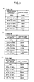
- FIGS. 3A to 3C illustrate correspondence tables each indicating correspondence between the brightness of an image and the lamp power.
- the correspondence tables correspond to the correspondence information.
- table #3 is selected. If the range of the illuminance obtained by the illuminance sensor 14 is 300 lx or more and less than 600 lx, table #2 is selected. If the range of the illuminance obtained by the illuminance sensor 14 is 600 lx or more, table #1 is selected.
- the lamp power is set to fall within the range of 140 W to 240 W in accordance with the brightness (gradation level) of an image.
- the lamp power is set to fall within the range of 140 W to 215 W in accordance with the brightness (gradation level) of the image.
- the lamp power is set to fall within the range of 140 W to 190 W in accordance with the brightness (gradation level) of the image. Namely, in the present embodiment, as the illuminance becomes higher, an upper limit of the lamp power and an output of the lamp power with respect to the brightness of an image are set to be larger.
- the lamp control unit 12 controls the lamp 13 in accordance with a value of the lamp power determined by the total control unit 10.
- the external connection unit 17 is connected with a PC, a DVD player and the like to receive image data and video data.
- the image data processing unit 15 sends, to the image data projection unit 16, the image data received from the external connection unit 17.
- the image data processing unit 15 also computes the brightness (gradation level) of the image data and executes a process of increasing the gradation level of the image data in accordance with the brightness of the image data.
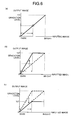
- FIGS. 6(a) to 6(c) are explanatory views illustrating the detail of the process of increasing the gradation level of the image data in accordance with the brightness of the image data.
- the abscissa represents the brightness of inputted image data
- the ordinate represents the brightness of image data to be outputted.
- the gradation level of 0 to 127 is used as a unit of the drawings.
- the brightness of inputted image data and the brightness of outputted image data are in proportion of 1:1 in a normal state.
- a range up to a circled point is the range of the brightness to be used in the inputted image data.
- the image data processing unit 15 increases the gradation level of the image data so as to match the most bright gradation level of the inputted image data with the 127-gradation level.
- the image data projection unit 16 projects the image data received from the image data processing unit 15.
- the image data projection unit 16 does not project unprocessed image data, but projects, with the lamp power determined by the total control unit 10, the image data with the gradation value increased by the image data processing unit 15.
- the illuminance sensor 14 measures the illuminance and inputs a measured value into the total control unit 10.
- FIG. 4 is a flow chart illustrating the operation of selecting a table based on the illuminance value measured with the illuminance sensor 14.
- the total control unit 10 obtains the illuminance measured by the illuminance sensor 14 (Step S101).
- the total control unit 10 selects a table corresponding to the current illuminance by referring to a table stored in the set information storage unit 11 illustrated in FIG. 2 (step S102). More specifically, if the illuminance is 600 lx or more, the table #1 is selected (step S103).
- the table #2 is selected (step S104). If the illuminance is less than 300 lx, the table #3 is selected (step S105).
- the above-stated operation is executed in a periodic basis, that is, every other second for example, and a table corresponding to the surrounding brightness of the projector 1 is selected at each of that moment.
- FIG. 5 is a flow chart illustrating the flow of the process of determining the lamp power from the brightness of inputted image data.
- the total control unit 10 obtains the brightness of an image from the image data processing unit 15 (step S201).
- the image data processing unit 15 performs, on the image data, the process of increasing the gradation level of the image data based on the brightness of the image (step S202).
- the total control unit 10 obtains lamp power corresponding to the brightness of the image from the selected table (step S203).
- the total control unit 10 sets the obtained lamp power for the lamp control unit 12 (Step S204).
- a series of these processes are executed, for example, in each frame of the image data, so that the lamp power to be set corresponds to the brightness of the image data at the time of each frame.
- an output range of the lamp power which is determined in accordance with the brightness of image data, is determined in accordance with the illuminance obtained by the illuminance sensor 14.
- an upper limit of the lamp power range is set higher and a lamp power value corresponding to the brightness of each image data is also set to be high.
- the upper limit of the lamp power range is set lower and a lamp power value corresponding to the brightness of each image data is also set to be low.
- the final lamp power is determined based on two input values, an input value indicating the illuminance and an input value indicating the brightness (gradation level) of image data. As a result, the lamp power is set as an appropriate value corresponding to each of the input values.
- the table to be used is determined based on the illuminance range in the above-described embodiment, the illuminance range may suitably be changed in accordance with features of the projector 1. Further, it is not needed to prepare three tables based on the illuminance, but at least two or more tables may be prepared as options for selection. Moreover, the correspondence between the brightness of image data and the light power may suitably be changed.
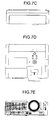
- FIGS. 7A to 7G illustrate one example of the shape of the projector 1.
- FIG. 7A is a perspective view of an image projection apparatus as viewed from the front side.
- FIG. 7A is a perspective view of the image projection apparatus as viewed from the rear side.
- FIG. 7C is a rear view of the image projection apparatus.
- FIG. 7D is a top view of the image projection apparatus.
- FIG. 7E is a front view of the image projection apparatus.
- FIG. 7F is a bottom view of the image projection apparatus.
- FIG. 7G is a side view of the image projection apparatus.
- FIG. 7H is a side view of the image projection apparatus.
- the present invention provides the advantage that the output of a lamp can appropriately be adjusted with respect to two input values: a value indicating the number of gradations of an inputted image and a value indicating the illuminance of the room where the image projection apparatus is used.
Landscapes
- Engineering & Computer Science (AREA)
- Multimedia (AREA)
- Signal Processing (AREA)
- Physics & Mathematics (AREA)
- General Physics & Mathematics (AREA)
- Optics & Photonics (AREA)
- Nonlinear Science (AREA)
- Crystallography & Structural Chemistry (AREA)
- Chemical & Material Sciences (AREA)
- Mathematical Physics (AREA)
- Transforming Electric Information Into Light Information (AREA)
- Projection Apparatus (AREA)
- Circuit Arrangement For Electric Light Sources In General (AREA)
- Control Of Indicators Other Than Cathode Ray Tubes (AREA)
- Liquid Crystal Display Device Control (AREA)
- Television Receiver Circuits (AREA)
Abstract
Description
- The present invention relates to an image projection apparatus and a method of controlling the same.
- Conventionally, projectors are adapted to perform various processes in order to adjust the quality of an image to be projected. For example, a projector disclosed in Japanese Patent Application Laid-open No.
2002-156951 - A projector disclosed in Japanese Patent Application Laid-open No.
2000-131668 - However, in the aforementioned conventional technologies, the lamp output could be adjusted only in accordance with any one of two input values: a value indicating the brightness of the room where the projector is used; and a value indicating the number of gradations of an input signal. Accordingly, even when the lamp output was desired to be decreased in accordance with a dark image, the lamp output was sometimes increased according to a bright room. Thus, there were possibilities that the effects obtained by adjustment of the lamp were offset.
- The present invention has been made in view of the above-described circumstances, and an object of the present invention is to provide an image projection apparatus that can appropriately adjust the output of a lamp in accordance with two input values: a value indicating the number of gradations of an inputted image; and a value indicating the illuminance of the room where the image projection apparatus is used.
- It is an aim of the present invention to at least partially solve the problems in the conventional technology.
- According to the present invention, there is provided: an image projection apparatus, comprising: an external connection unit configured to receive an input of image data; an illuminance sensor configured to measure surrounding illuminance; an image data processing unit configured to increase a gradation value of the image data in accordance with brightness of the image data; a set information storage unit configured to store therein at least two or more pieces of correspondence information for each range of the obtained illuminance, the pieces of correspondence information indicating correspondence between the brightness of the image data and lamp power of a lamp serving as a light source, the lamp power increasing in accordance with the brightness; a total control unit configured to determine the lamp power of the lamp by referring to a table indicating the correspondence information stored in the set information storage unit, based on the obtained brightness of the image and the illuminance; and a projection unit configured to project with the determined lamp power the image data having the gradation value increased.
- In the above-described image projection apparatus, in the correspondence information, a value of the lamp power is set lower as the illuminance becomes lower.
- The present invention also provides a method for controlling an image projection apparatus, the image projection apparatus including an external connection unit configured to receive an input of image data, an illuminance sensor configured to measure surrounding illuminance, and a set information storage unit configured to store therein at least two or more pieces of correspondence information for each range of the obtained illuminance, the pieces of correspondence information indicating correspondence between the brightness of the image data and lamp power of a lamp serving as a light source, the lamp power increasing in accordance with the brightness, the method comprising: an image data processing step of obtaining brightness from the inputted image data and increasing a gradation value of the image data in accordance with the brightness of the image data; a total control step of determining the lamp power of the lamp by referring to the correspondence information stored in the set information storage unit, based on the obtained brightness of the image and the illuminance; and a projection step of projecting with the determined lamp power the image data having the gradation value increased.
- In the above-described method for controlling an image projection apparatus, in the correspondence information, a value of the lamp power is set lower as the illuminance becomes lower.
- The above and other objects, features, advantages and technical and industrial significance of this invention will be better understood by reading the following detailed description of presently preferred embodiments of the invention, when considered in connection with the accompanying drawings, in which:
-
FIG. 1 is a block diagram illustrating a functional configuration of an image projection apparatus according to an embodiment. -
FIG. 2 a diagram illustrating one example of a relationship between obtained illuminance and tables to be used in the embodiment. -
FIGS. 3(a) to 3(c) each of that is a diagram illustrating a relationship between brightness of image data and lamp power in each table in the embodiment. -
FIG. 4 is a flow chart illustrating the flow of a process of selecting a table in accordance with the illuminance in the embodiment. -
FIG. 5 is a flow chart illustrating the flow of a process of determining the lamp power in the embodiment. -
FIGS. 6(a) to 6(c) are explanatory views illustrating a process of electrically amplifying the brightness of inputted image data in the embodiment. -
FIG. 7A is a perspective view of an image projection apparatus, as viewed from the front side, including an information processor embodied according to each embodiment. -
FIG. 7B is a perspective view of the image projection apparatus, as viewed from the rear side, including the information processor embodied according to each embodiment. -
FIG. 7C is a rear view of the image projection apparatus including the information processor embodied according to each embodiment. -
FIG. 7D is a top view of the image projection apparatus including the information processor embodied according to each embodiment. -
FIG. 7E is a front view of the image projection apparatus including the information processor embodied according to each embodiment. -
FIG. 7F is a bottom view of the image projection apparatus including the information processor embodied according to each embodiment. -
FIG. 7G is a side view of the image projection apparatus including the information processor embodied according to the embodiment. -
FIG. 7H is a side view of the image projection apparatus including the information processor embodied according to each embodiment. - Hereinbelow, an embodiment that embodies an image projection apparatus of the present invention will be described.
FIG. 1 is a block diagram illustrating a functional configuration of aprojector 1 that is an image projection apparatus. As illustrated inFIG. 1 , theprojector 1 includes atotal control unit 10, a setinformation storage unit 11, alamp control unit 12, alamp 13 serving as a light source, anilluminance sensor 14, an image data processing unit 15, an imagedata projection unit 16, and anexternal connection unit 17. For example, thetotal control unit 10 is configured by hardware such as a CPU to control the entire apparatus. More specifically, thetotal control unit 10 also performs a process of determining a final lamp output based on the input values obtained from theilluminance sensor 14 and the image data processing unit 15. - The set
information storage unit 11 stores tables for setting an upper limit of the lamp power in accordance with the illuminance of the room where the image projection apparatus is used.FIG. 2 illustrates a correspondence table to be used for determining which table to select for determining the lamp power based on the range of illuminance.FIGS. 3A to 3C illustrate correspondence tables each indicating correspondence between the brightness of an image and the lamp power. The correspondence tables correspond to the correspondence information. In the present embodiment, as illustrated inFIG. 2 , if the range of the illuminance obtained by theilluminance sensor 14 is less than 300 lx,table # 3 is selected. If the range of the illuminance obtained by theilluminance sensor 14 is 300 lx or more and less than 600 lx,table # 2 is selected. If the range of the illuminance obtained by theilluminance sensor 14 is 600 lx or more,table # 1 is selected. - In
table # 1, the lamp power is set to fall within the range of 140 W to 240 W in accordance with the brightness (gradation level) of an image. Intable # 2, the lamp power is set to fall within the range of 140 W to 215 W in accordance with the brightness (gradation level) of the image. Intable # 3, the lamp power is set to fall within the range of 140 W to 190 W in accordance with the brightness (gradation level) of the image. Namely, in the present embodiment, as the illuminance becomes higher, an upper limit of the lamp power and an output of the lamp power with respect to the brightness of an image are set to be larger. - The
lamp control unit 12 controls thelamp 13 in accordance with a value of the lamp power determined by thetotal control unit 10. Theexternal connection unit 17 is connected with a PC, a DVD player and the like to receive image data and video data. The image data processing unit 15 sends, to the imagedata projection unit 16, the image data received from theexternal connection unit 17. The image data processing unit 15 also computes the brightness (gradation level) of the image data and executes a process of increasing the gradation level of the image data in accordance with the brightness of the image data.FIGS. 6(a) to 6(c) are explanatory views illustrating the detail of the process of increasing the gradation level of the image data in accordance with the brightness of the image data. InFIGS. 6(a) to 6(c) , the abscissa represents the brightness of inputted image data, and the ordinate represents the brightness of image data to be outputted. The gradation level of 0 to 127 is used as a unit of the drawings. - As illustrated in
FIG. 6(a) , the brightness of inputted image data and the brightness of outputted image data are in proportion of 1:1 in a normal state. InFIG. 6(a) , a range up to a circled point is the range of the brightness to be used in the inputted image data. In this case, as illustrated inFIG. 6(b) , supposing that the maximum brightness that can be processed by the image data processing unit 15 is a 127-gradation level, the image data processing unit 15 increases the gradation level of the image data so as to match the most bright gradation level of the inputted image data with the 127-gradation level. For example, when the brightness of the brightest image is expressed as 100% and the brightness of inputted image data is 50%, image processing is performed to amplify the gradation level twofold. Then, as illustrated inFIG. 6(c) , the lamp power is reduced for optical correction in proportion to the brightness increased by the image processing of the gradation level. As a result, an energy saving effect can be realized without changing the brightness of outputted image, that is, without changing the apparent brightness viewed by a user. - The image
data projection unit 16 projects the image data received from the image data processing unit 15. The imagedata projection unit 16 does not project unprocessed image data, but projects, with the lamp power determined by thetotal control unit 10, the image data with the gradation value increased by the image data processing unit 15. Theilluminance sensor 14 measures the illuminance and inputs a measured value into thetotal control unit 10. - Operation of the present embodiment is now described with reference to the flow charts of
FIGS. 4 and 5. FIG. 4 is a flow chart illustrating the operation of selecting a table based on the illuminance value measured with theilluminance sensor 14. As illustrated inFIG. 4 , thetotal control unit 10 obtains the illuminance measured by the illuminance sensor 14 (Step S101). Thetotal control unit 10 then selects a table corresponding to the current illuminance by referring to a table stored in the setinformation storage unit 11 illustrated inFIG. 2 (step S102). More specifically, if the illuminance is 600 lx or more, thetable # 1 is selected (step S103). If the illuminance is 300 lx or more and less than 600 lx, thetable # 2 is selected (step S104). If the illuminance is less than 300 lx, thetable # 3 is selected (step S105). The above-stated operation is executed in a periodic basis, that is, every other second for example, and a table corresponding to the surrounding brightness of theprojector 1 is selected at each of that moment. - Next,
FIG. 5 is a flow chart illustrating the flow of the process of determining the lamp power from the brightness of inputted image data. As illustrated inFIG. 5 , first, thetotal control unit 10 obtains the brightness of an image from the image data processing unit 15 (step S201). Next, the image data processing unit 15 performs, on the image data, the process of increasing the gradation level of the image data based on the brightness of the image (step S202). Next, thetotal control unit 10 obtains lamp power corresponding to the brightness of the image from the selected table (step S203). Thetotal control unit 10 then sets the obtained lamp power for the lamp control unit 12 (Step S204). A series of these processes are executed, for example, in each frame of the image data, so that the lamp power to be set corresponds to the brightness of the image data at the time of each frame. - According to the
projector 1 of the present embodiment described above, an output range of the lamp power, which is determined in accordance with the brightness of image data, is determined in accordance with the illuminance obtained by theilluminance sensor 14. In other words, when the illuminance is high, an upper limit of the lamp power range is set higher and a lamp power value corresponding to the brightness of each image data is also set to be high. On the contrary, when the illuminance is low, the upper limit of the lamp power range is set lower and a lamp power value corresponding to the brightness of each image data is also set to be low. Thus, the final lamp power is determined based on two input values, an input value indicating the illuminance and an input value indicating the brightness (gradation level) of image data. As a result, the lamp power is set as an appropriate value corresponding to each of the input values. - Although the table to be used is determined based on the illuminance range in the above-described embodiment, the illuminance range may suitably be changed in accordance with features of the
projector 1. Further, it is not needed to prepare three tables based on the illuminance, but at least two or more tables may be prepared as options for selection. Moreover, the correspondence between the brightness of image data and the light power may suitably be changed. -
FIGS. 7A to 7G illustrate one example of the shape of theprojector 1.FIG. 7A is a perspective view of an image projection apparatus as viewed from the front side.FIG. 7A is a perspective view of the image projection apparatus as viewed from the rear side.FIG. 7C is a rear view of the image projection apparatus.FIG. 7D is a top view of the image projection apparatus.FIG. 7E is a front view of the image projection apparatus.FIG. 7F is a bottom view of the image projection apparatus.FIG. 7G is a side view of the image projection apparatus.FIG. 7H is a side view of the image projection apparatus. - The present invention provides the advantage that the output of a lamp can appropriately be adjusted with respect to two input values: a value indicating the number of gradations of an inputted image and a value indicating the illuminance of the room where the image projection apparatus is used.
- Although the invention has been described with respect to specific embodiments for a complete and clear disclosure, the appended claims are not to be thus limited but are to be construed as embodying all modifications and alternative constructions that may occur to one skilled in the art that fairly fall within the basic teaching herein set forth.
- The present application claims priority to and incorporates by reference the entire contents of Japanese Patent Application No.
2012-286290
Claims (4)
- An image projection apparatus, comprising:an external connection unit (17) configured to receive an input of image data;an illuminance sensor (14) configured to measure surrounding illuminance;an image data processing unit (15) configured to increase a gradation value of the image data in accordance with brightness of the image data;a set information storage unit (11) configured to store therein at least two or more pieces of correspondence information for each range of the obtained illuminance, the pieces of correspondence information indicating correspondence between the brightness of the image data and lamp power of a lamp (13) serving as a light source, the lamp power increasing in accordance with the brightness;a total control unit (10) configured to determine the lamp power of the lamp by referring to a table indicating the correspondence information stored in the set information storage unit, based on the obtained brightness of the image and the illuminance; anda projection unit (16) configured to project with the determined lamp power the image data having the gradation value increased, whereinin the correspondence information, a value of the lamp power is set lower as the illuminance becomes lower.
- The image projection apparatus according to claim 1, wherein
the total control unit (10) obtains the illuminance measured by the illuminance sensor (14) at each specified time, and determines the correspondence information to be used for determining the lamp power, based on the illuminance obtained for determining the lamp power. - The image projection apparatus according to claim 1 or 2, wherein
the total control unit (10) determines the lamp power based on the brightness in every frame of the inputted image data. - A method for controlling an image projection apparatus, the image projection apparatus including an external connection unit (17) configured to receive an input of image data, an illuminance sensor (14) configured to measure surrounding illuminance, and a set information storage unit (11) configured to store therein at least two or more pieces of correspondence information for each range of the obtained illuminance, the pieces of correspondence information indicating correspondence between the brightness of the image data and lamp power of a lamp (13) serving as a light source, the lamp power increasing in accordance with the brightness, the method comprising:an image data processing step of obtaining brightness from the inputted image data and increasing a gradation value of the image data in accordance with the brightness of the image data;a total control step of determining the lamp power of the lamp (13) by referring to the correspondence information stored in the set information storage unit (11), based on the obtained brightness of the image and the illuminance; anda projection step of projecting with the determined lamp power the image data having the gradation value increased, whereinin the correspondence information, a value of the lamp power is set lower as the illuminance becomes lower.
Applications Claiming Priority (1)
| Application Number | Priority Date | Filing Date | Title |
|---|---|---|---|
| JP2012286290A JP2014130170A (en) | 2012-12-27 | 2012-12-27 | Image projection apparatus and control method |
Publications (3)
| Publication Number | Publication Date |
|---|---|
| EP2750388A2 true EP2750388A2 (en) | 2014-07-02 |
| EP2750388A3 EP2750388A3 (en) | 2016-09-07 |
| EP2750388B1 EP2750388B1 (en) | 2019-04-03 |
Family
ID=49882866
Family Applications (1)
| Application Number | Title | Priority Date | Filing Date |
|---|---|---|---|
| EP13198577.2A Not-in-force EP2750388B1 (en) | 2012-12-27 | 2013-12-19 | Image projection apparatus and method of controlling same |
Country Status (4)
| Country | Link |
|---|---|
| US (1) | US9329466B2 (en) |
| EP (1) | EP2750388B1 (en) |
| JP (1) | JP2014130170A (en) |
| CN (1) | CN103905759B (en) |
Families Citing this family (9)
| Publication number | Priority date | Publication date | Assignee | Title |
|---|---|---|---|---|
| US20170310938A1 (en) * | 2016-04-25 | 2017-10-26 | Canon Kabushiki Kaisha | Projection display apparatus and projection display system |
| TWI653563B (en) * | 2016-05-24 | 2019-03-11 | 仁寶電腦工業股份有限公司 | Projection touch image selection method |
| CN106686318B (en) * | 2016-12-23 | 2019-12-24 | 杭州华橙网络科技有限公司 | Control method and device for reducing radiation of infrared lamp |
| CN108957924B (en) * | 2017-05-24 | 2021-07-23 | 深圳光峰科技股份有限公司 | Laser lighting equipment and projection system using the same |
| CN108471525B (en) * | 2018-03-27 | 2020-07-17 | 百度在线网络技术(北京)有限公司 | Control method and device for projector and projector for implementing method |
| CN108663882B (en) * | 2018-04-16 | 2021-01-05 | 苏州佳世达光电有限公司 | Light source system and method for generating light combination beam with target brightness value |
| CN111526343B (en) * | 2019-02-01 | 2022-03-01 | 中国电影器材有限责任公司 | A digital cinema projection method and system |
| CN111526344B (en) * | 2019-02-01 | 2021-12-14 | 中国电影器材有限责任公司 | A digital cinema projection method and system |
| CN118660144B (en) * | 2024-08-19 | 2025-02-28 | 深圳市大屏影音技术有限公司 | A visual signal processing system and method for projection equipment based on smart home |
Citations (2)
| Publication number | Priority date | Publication date | Assignee | Title |
|---|---|---|---|---|
| JP2000131668A (en) | 1998-10-26 | 2000-05-12 | Hitachi Ltd | Light source dimmer for liquid crystal projector |
| JP2002156951A (en) | 2000-08-14 | 2002-05-31 | Canon Inc | Display device |
Family Cites Families (19)
| Publication number | Priority date | Publication date | Assignee | Title |
|---|---|---|---|---|
| US6847374B2 (en) * | 2000-07-31 | 2005-01-25 | Seiko Epson Corporation | Environment-compliant image display system and program |
| US6891524B2 (en) | 2000-08-14 | 2005-05-10 | Canon Kabushiki Kaisha | Display device with amplification control |
| JP3661692B2 (en) * | 2003-05-30 | 2005-06-15 | セイコーエプソン株式会社 | Illumination device, projection display device, and driving method thereof |
| JP2005031572A (en) * | 2003-07-11 | 2005-02-03 | Sharp Corp | Projector image quality correction system |
| CN100591108C (en) * | 2004-03-05 | 2010-02-17 | 松下电器产业株式会社 | Image signal processing method, image signal processing device and image display device |
| JP4281593B2 (en) * | 2004-03-24 | 2009-06-17 | セイコーエプソン株式会社 | Projector control |
| WO2007029420A1 (en) * | 2005-09-08 | 2007-03-15 | Sharp Kabushiki Kaisha | Image display device |
| JP4059910B2 (en) * | 2005-11-11 | 2008-03-12 | シャープ株式会社 | Liquid crystal display |
| JP5014154B2 (en) * | 2006-08-29 | 2012-08-29 | パナソニック株式会社 | Image display method and image display apparatus |
| WO2008117784A1 (en) * | 2007-03-26 | 2008-10-02 | Nec Corporation | Portable phone terminal, image display controlling method, program thereof, and program recording medium |
| JP2009031554A (en) * | 2007-07-27 | 2009-02-12 | Sharp Corp | Video display device and video display method thereof |
| JP5045312B2 (en) * | 2007-08-30 | 2012-10-10 | セイコーエプソン株式会社 | Image display device, image display method, image display program, and recording medium on which image display program is recorded |
| JP2009134237A (en) * | 2007-11-02 | 2009-06-18 | Hitachi Displays Ltd | Display device |
| US20090122087A1 (en) * | 2007-11-02 | 2009-05-14 | Junichi Maruyama | Display device |
| JP5258396B2 (en) * | 2008-06-03 | 2013-08-07 | ローム株式会社 | Liquid crystal display device control circuit and liquid crystal display system |
| JP2010113009A (en) * | 2008-11-04 | 2010-05-20 | Seiko Epson Corp | Image display device, illuminance acquisition method, illuminance acquisition program, and recording medium |
| JPWO2011033669A1 (en) * | 2009-09-18 | 2013-02-07 | 株式会社東芝 | Image display device |
| US20120075353A1 (en) * | 2010-09-27 | 2012-03-29 | Ati Technologies Ulc | System and Method for Providing Control Data for Dynamically Adjusting Lighting and Adjusting Video Pixel Data for a Display to Substantially Maintain Image Display Quality While Reducing Power Consumption |
| JP2013101207A (en) | 2011-11-08 | 2013-05-23 | Ricoh Co Ltd | Projector |
-
2012
- 2012-12-27 JP JP2012286290A patent/JP2014130170A/en active Pending
-
2013
- 2013-12-09 US US14/100,342 patent/US9329466B2/en not_active Expired - Fee Related
- 2013-12-19 EP EP13198577.2A patent/EP2750388B1/en not_active Not-in-force
- 2013-12-23 CN CN201310717543.0A patent/CN103905759B/en not_active Expired - Fee Related
Patent Citations (2)
| Publication number | Priority date | Publication date | Assignee | Title |
|---|---|---|---|---|
| JP2000131668A (en) | 1998-10-26 | 2000-05-12 | Hitachi Ltd | Light source dimmer for liquid crystal projector |
| JP2002156951A (en) | 2000-08-14 | 2002-05-31 | Canon Inc | Display device |
Also Published As
| Publication number | Publication date |
|---|---|
| US20140184924A1 (en) | 2014-07-03 |
| EP2750388A3 (en) | 2016-09-07 |
| US9329466B2 (en) | 2016-05-03 |
| JP2014130170A (en) | 2014-07-10 |
| EP2750388B1 (en) | 2019-04-03 |
| CN103905759B (en) | 2018-01-30 |
| CN103905759A (en) | 2014-07-02 |
Similar Documents
| Publication | Publication Date | Title |
|---|---|---|
| US9329466B2 (en) | Image projection apparatus in which lamp power is determined by measured illuminance | |
| US7631974B2 (en) | Image display method and image display device | |
| JP5556089B2 (en) | Image display device and image adjustment method | |
| JP5320865B2 (en) | Projector and projector control method | |
| CN100550123C (en) | Method and device for automatically determining brightness of display and display | |
| US20130082993A1 (en) | Apparatus and method for controlling image output in projector apparatus | |
| JP5472576B2 (en) | Display device, program, and information storage medium | |
| JP6516302B2 (en) | Image display apparatus and light source light control method | |
| US20130063500A1 (en) | Light source control apparatus, image display apparatus and light source control method | |
| CN109976070B (en) | Image projection apparatus, control method of image projection apparatus, and storage medium | |
| JP2017203948A (en) | Display device and control method thereof | |
| JP2008209507A (en) | Brightness correction control method | |
| JP5327470B2 (en) | Image display device and image adjustment method | |
| JP4573719B2 (en) | Image display device, white balance adjustment device, white balance adjustment system, and white balance adjustment method | |
| KR20110052120A (en) | Method and apparatus for driving plasma display panel | |
| JP2015154163A (en) | Projection type display device and control method of the same | |
| TWI541785B (en) | Optimization method and system of lcd white balance real-time selection | |
| JP2010224099A (en) | Display device, program, and information storage medium | |
| JP5692546B2 (en) | Image display device and image adjustment method | |
| JP2008145644A (en) | Display device | |
| KR20120073877A (en) | A multivision display device and a method of adjusting brightness thereof | |
| KR20110093463A (en) | Projector control method and projector using this method | |
| KR20110093459A (en) | Projector control method and projector using this method | |
| WO2010103798A1 (en) | Display control apparatus and display control method | |
| JP2018010062A (en) | Projection type display device and projection type display device control method |
Legal Events
| Date | Code | Title | Description |
|---|---|---|---|
| 17P | Request for examination filed |
Effective date: 20131219 |
|
| AK | Designated contracting states |
Kind code of ref document: A2 Designated state(s): AL AT BE BG CH CY CZ DE DK EE ES FI FR GB GR HR HU IE IS IT LI LT LU LV MC MK MT NL NO PL PT RO RS SE SI SK SM TR |
|
| AX | Request for extension of the european patent |
Extension state: BA ME |
|
| PUAI | Public reference made under article 153(3) epc to a published international application that has entered the european phase |
Free format text: ORIGINAL CODE: 0009012 |
|
| PUAL | Search report despatched |
Free format text: ORIGINAL CODE: 0009013 |
|
| AK | Designated contracting states |
Kind code of ref document: A3 Designated state(s): AL AT BE BG CH CY CZ DE DK EE ES FI FR GB GR HR HU IE IS IT LI LT LU LV MC MK MT NL NO PL PT RO RS SE SI SK SM TR |
|
| AX | Request for extension of the european patent |
Extension state: BA ME |
|
| RIC1 | Information provided on ipc code assigned before grant |
Ipc: H04N 9/31 20060101AFI20160729BHEP Ipc: H04N 5/58 20060101ALI20160729BHEP |
|
| GRAP | Despatch of communication of intention to grant a patent |
Free format text: ORIGINAL CODE: EPIDOSNIGR1 |
|
| STAA | Information on the status of an ep patent application or granted ep patent |
Free format text: STATUS: GRANT OF PATENT IS INTENDED |
|
| INTG | Intention to grant announced |
Effective date: 20181026 |
|
| GRAS | Grant fee paid |
Free format text: ORIGINAL CODE: EPIDOSNIGR3 |
|
| GRAA | (expected) grant |
Free format text: ORIGINAL CODE: 0009210 |
|
| STAA | Information on the status of an ep patent application or granted ep patent |
Free format text: STATUS: THE PATENT HAS BEEN GRANTED |
|
| AK | Designated contracting states |
Kind code of ref document: B1 Designated state(s): AL AT BE BG CH CY CZ DE DK EE ES FI FR GB GR HR HU IE IS IT LI LT LU LV MC MK MT NL NO PL PT RO RS SE SI SK SM TR |
|
| REG | Reference to a national code |
Ref country code: GB Ref legal event code: FG4D |
|
| REG | Reference to a national code |
Ref country code: CH Ref legal event code: EP Ref country code: AT Ref legal event code: REF Ref document number: 1117228 Country of ref document: AT Kind code of ref document: T Effective date: 20190415 |
|
| REG | Reference to a national code |
Ref country code: DE Ref legal event code: R096 Ref document number: 602013053226 Country of ref document: DE |
|
| REG | Reference to a national code |
Ref country code: IE Ref legal event code: FG4D |
|
| REG | Reference to a national code |
Ref country code: NL Ref legal event code: MP Effective date: 20190403 |
|
| REG | Reference to a national code |
Ref country code: LT Ref legal event code: MG4D |
|
| REG | Reference to a national code |
Ref country code: AT Ref legal event code: MK05 Ref document number: 1117228 Country of ref document: AT Kind code of ref document: T Effective date: 20190403 |
|
| PG25 | Lapsed in a contracting state [announced via postgrant information from national office to epo] |
Ref country code: NL Free format text: LAPSE BECAUSE OF FAILURE TO SUBMIT A TRANSLATION OF THE DESCRIPTION OR TO PAY THE FEE WITHIN THE PRESCRIBED TIME-LIMIT Effective date: 20190403 |
|
| PG25 | Lapsed in a contracting state [announced via postgrant information from national office to epo] |
Ref country code: FI Free format text: LAPSE BECAUSE OF FAILURE TO SUBMIT A TRANSLATION OF THE DESCRIPTION OR TO PAY THE FEE WITHIN THE PRESCRIBED TIME-LIMIT Effective date: 20190403 Ref country code: LT Free format text: LAPSE BECAUSE OF FAILURE TO SUBMIT A TRANSLATION OF THE DESCRIPTION OR TO PAY THE FEE WITHIN THE PRESCRIBED TIME-LIMIT Effective date: 20190403 Ref country code: AL Free format text: LAPSE BECAUSE OF FAILURE TO SUBMIT A TRANSLATION OF THE DESCRIPTION OR TO PAY THE FEE WITHIN THE PRESCRIBED TIME-LIMIT Effective date: 20190403 Ref country code: PT Free format text: LAPSE BECAUSE OF FAILURE TO SUBMIT A TRANSLATION OF THE DESCRIPTION OR TO PAY THE FEE WITHIN THE PRESCRIBED TIME-LIMIT Effective date: 20190803 Ref country code: ES Free format text: LAPSE BECAUSE OF FAILURE TO SUBMIT A TRANSLATION OF THE DESCRIPTION OR TO PAY THE FEE WITHIN THE PRESCRIBED TIME-LIMIT Effective date: 20190403 Ref country code: CZ Free format text: LAPSE BECAUSE OF FAILURE TO SUBMIT A TRANSLATION OF THE DESCRIPTION OR TO PAY THE FEE WITHIN THE PRESCRIBED TIME-LIMIT Effective date: 20190403 Ref country code: SE Free format text: LAPSE BECAUSE OF FAILURE TO SUBMIT A TRANSLATION OF THE DESCRIPTION OR TO PAY THE FEE WITHIN THE PRESCRIBED TIME-LIMIT Effective date: 20190403 Ref country code: NO Free format text: LAPSE BECAUSE OF FAILURE TO SUBMIT A TRANSLATION OF THE DESCRIPTION OR TO PAY THE FEE WITHIN THE PRESCRIBED TIME-LIMIT Effective date: 20190703 Ref country code: HR Free format text: LAPSE BECAUSE OF FAILURE TO SUBMIT A TRANSLATION OF THE DESCRIPTION OR TO PAY THE FEE WITHIN THE PRESCRIBED TIME-LIMIT Effective date: 20190403 |
|
| PG25 | Lapsed in a contracting state [announced via postgrant information from national office to epo] |
Ref country code: GR Free format text: LAPSE BECAUSE OF FAILURE TO SUBMIT A TRANSLATION OF THE DESCRIPTION OR TO PAY THE FEE WITHIN THE PRESCRIBED TIME-LIMIT Effective date: 20190704 Ref country code: LV Free format text: LAPSE BECAUSE OF FAILURE TO SUBMIT A TRANSLATION OF THE DESCRIPTION OR TO PAY THE FEE WITHIN THE PRESCRIBED TIME-LIMIT Effective date: 20190403 Ref country code: PL Free format text: LAPSE BECAUSE OF FAILURE TO SUBMIT A TRANSLATION OF THE DESCRIPTION OR TO PAY THE FEE WITHIN THE PRESCRIBED TIME-LIMIT Effective date: 20190403 Ref country code: BG Free format text: LAPSE BECAUSE OF FAILURE TO SUBMIT A TRANSLATION OF THE DESCRIPTION OR TO PAY THE FEE WITHIN THE PRESCRIBED TIME-LIMIT Effective date: 20190703 Ref country code: RS Free format text: LAPSE BECAUSE OF FAILURE TO SUBMIT A TRANSLATION OF THE DESCRIPTION OR TO PAY THE FEE WITHIN THE PRESCRIBED TIME-LIMIT Effective date: 20190403 |
|
| PG25 | Lapsed in a contracting state [announced via postgrant information from national office to epo] |
Ref country code: AT Free format text: LAPSE BECAUSE OF FAILURE TO SUBMIT A TRANSLATION OF THE DESCRIPTION OR TO PAY THE FEE WITHIN THE PRESCRIBED TIME-LIMIT Effective date: 20190403 Ref country code: IS Free format text: LAPSE BECAUSE OF FAILURE TO SUBMIT A TRANSLATION OF THE DESCRIPTION OR TO PAY THE FEE WITHIN THE PRESCRIBED TIME-LIMIT Effective date: 20190803 |
|
| REG | Reference to a national code |
Ref country code: DE Ref legal event code: R097 Ref document number: 602013053226 Country of ref document: DE |
|
| PG25 | Lapsed in a contracting state [announced via postgrant information from national office to epo] |
Ref country code: EE Free format text: LAPSE BECAUSE OF FAILURE TO SUBMIT A TRANSLATION OF THE DESCRIPTION OR TO PAY THE FEE WITHIN THE PRESCRIBED TIME-LIMIT Effective date: 20190403 Ref country code: RO Free format text: LAPSE BECAUSE OF FAILURE TO SUBMIT A TRANSLATION OF THE DESCRIPTION OR TO PAY THE FEE WITHIN THE PRESCRIBED TIME-LIMIT Effective date: 20190403 Ref country code: DK Free format text: LAPSE BECAUSE OF FAILURE TO SUBMIT A TRANSLATION OF THE DESCRIPTION OR TO PAY THE FEE WITHIN THE PRESCRIBED TIME-LIMIT Effective date: 20190403 Ref country code: SK Free format text: LAPSE BECAUSE OF FAILURE TO SUBMIT A TRANSLATION OF THE DESCRIPTION OR TO PAY THE FEE WITHIN THE PRESCRIBED TIME-LIMIT Effective date: 20190403 |
|
| PLBE | No opposition filed within time limit |
Free format text: ORIGINAL CODE: 0009261 |
|
| STAA | Information on the status of an ep patent application or granted ep patent |
Free format text: STATUS: NO OPPOSITION FILED WITHIN TIME LIMIT |
|
| PG25 | Lapsed in a contracting state [announced via postgrant information from national office to epo] |
Ref country code: SM Free format text: LAPSE BECAUSE OF FAILURE TO SUBMIT A TRANSLATION OF THE DESCRIPTION OR TO PAY THE FEE WITHIN THE PRESCRIBED TIME-LIMIT Effective date: 20190403 Ref country code: IT Free format text: LAPSE BECAUSE OF FAILURE TO SUBMIT A TRANSLATION OF THE DESCRIPTION OR TO PAY THE FEE WITHIN THE PRESCRIBED TIME-LIMIT Effective date: 20190403 |
|
| 26N | No opposition filed |
Effective date: 20200106 |
|
| PG25 | Lapsed in a contracting state [announced via postgrant information from national office to epo] |
Ref country code: TR Free format text: LAPSE BECAUSE OF FAILURE TO SUBMIT A TRANSLATION OF THE DESCRIPTION OR TO PAY THE FEE WITHIN THE PRESCRIBED TIME-LIMIT Effective date: 20190403 |
|
| PG25 | Lapsed in a contracting state [announced via postgrant information from national office to epo] |
Ref country code: SI Free format text: LAPSE BECAUSE OF FAILURE TO SUBMIT A TRANSLATION OF THE DESCRIPTION OR TO PAY THE FEE WITHIN THE PRESCRIBED TIME-LIMIT Effective date: 20190403 |
|
| REG | Reference to a national code |
Ref country code: CH Ref legal event code: PL |
|
| REG | Reference to a national code |
Ref country code: BE Ref legal event code: MM Effective date: 20191231 |
|
| PG25 | Lapsed in a contracting state [announced via postgrant information from national office to epo] |
Ref country code: MC Free format text: LAPSE BECAUSE OF FAILURE TO SUBMIT A TRANSLATION OF THE DESCRIPTION OR TO PAY THE FEE WITHIN THE PRESCRIBED TIME-LIMIT Effective date: 20190403 |
|
| PG25 | Lapsed in a contracting state [announced via postgrant information from national office to epo] |
Ref country code: LU Free format text: LAPSE BECAUSE OF NON-PAYMENT OF DUE FEES Effective date: 20191219 Ref country code: IE Free format text: LAPSE BECAUSE OF NON-PAYMENT OF DUE FEES Effective date: 20191219 |
|
| PG25 | Lapsed in a contracting state [announced via postgrant information from national office to epo] |
Ref country code: BE Free format text: LAPSE BECAUSE OF NON-PAYMENT OF DUE FEES Effective date: 20191231 Ref country code: CH Free format text: LAPSE BECAUSE OF NON-PAYMENT OF DUE FEES Effective date: 20191231 Ref country code: LI Free format text: LAPSE BECAUSE OF NON-PAYMENT OF DUE FEES Effective date: 20191231 |
|
| PGFP | Annual fee paid to national office [announced via postgrant information from national office to epo] |
Ref country code: FR Payment date: 20201223 Year of fee payment: 8 Ref country code: GB Payment date: 20201223 Year of fee payment: 8 Ref country code: DE Payment date: 20201211 Year of fee payment: 8 |
|
| PG25 | Lapsed in a contracting state [announced via postgrant information from national office to epo] |
Ref country code: CY Free format text: LAPSE BECAUSE OF FAILURE TO SUBMIT A TRANSLATION OF THE DESCRIPTION OR TO PAY THE FEE WITHIN THE PRESCRIBED TIME-LIMIT Effective date: 20190403 |
|
| PG25 | Lapsed in a contracting state [announced via postgrant information from national office to epo] |
Ref country code: HU Free format text: LAPSE BECAUSE OF FAILURE TO SUBMIT A TRANSLATION OF THE DESCRIPTION OR TO PAY THE FEE WITHIN THE PRESCRIBED TIME-LIMIT; INVALID AB INITIO Effective date: 20131219 Ref country code: MT Free format text: LAPSE BECAUSE OF FAILURE TO SUBMIT A TRANSLATION OF THE DESCRIPTION OR TO PAY THE FEE WITHIN THE PRESCRIBED TIME-LIMIT Effective date: 20190403 |
|
| PG25 | Lapsed in a contracting state [announced via postgrant information from national office to epo] |
Ref country code: MK Free format text: LAPSE BECAUSE OF FAILURE TO SUBMIT A TRANSLATION OF THE DESCRIPTION OR TO PAY THE FEE WITHIN THE PRESCRIBED TIME-LIMIT Effective date: 20190403 |
|
| REG | Reference to a national code |
Ref country code: DE Ref legal event code: R119 Ref document number: 602013053226 Country of ref document: DE |
|
| GBPC | Gb: european patent ceased through non-payment of renewal fee |
Effective date: 20211219 |
|
| PG25 | Lapsed in a contracting state [announced via postgrant information from national office to epo] |
Ref country code: GB Free format text: LAPSE BECAUSE OF NON-PAYMENT OF DUE FEES Effective date: 20211219 Ref country code: DE Free format text: LAPSE BECAUSE OF NON-PAYMENT OF DUE FEES Effective date: 20220701 |
|
| PG25 | Lapsed in a contracting state [announced via postgrant information from national office to epo] |
Ref country code: FR Free format text: LAPSE BECAUSE OF NON-PAYMENT OF DUE FEES Effective date: 20211231 |