EP2750366A1 - Image processing device and image reading apparatus - Google Patents
Image processing device and image reading apparatus Download PDFInfo
- Publication number
- EP2750366A1 EP2750366A1 EP13196188.0A EP13196188A EP2750366A1 EP 2750366 A1 EP2750366 A1 EP 2750366A1 EP 13196188 A EP13196188 A EP 13196188A EP 2750366 A1 EP2750366 A1 EP 2750366A1
- Authority
- EP
- European Patent Office
- Prior art keywords
- density
- value
- width
- input
- image
- Prior art date
- Legal status (The legal status is an assumption and is not a legal conclusion. Google has not performed a legal analysis and makes no representation as to the accuracy of the status listed.)
- Granted
Links
- 239000011521 glass Substances 0.000 claims description 5
- 230000014509 gene expression Effects 0.000 claims description 4
- 238000012886 linear function Methods 0.000 claims description 4
- 238000000034 method Methods 0.000 description 7
- 238000010586 diagram Methods 0.000 description 6
- 230000008901 benefit Effects 0.000 description 2
- 230000008030 elimination Effects 0.000 description 2
- 238000003379 elimination reaction Methods 0.000 description 2
- 238000010348 incorporation Methods 0.000 description 1
- 238000002372 labelling Methods 0.000 description 1
- 230000002093 peripheral effect Effects 0.000 description 1
Images




Classifications
-
- H—ELECTRICITY
- H04—ELECTRIC COMMUNICATION TECHNIQUE
- H04N—PICTORIAL COMMUNICATION, e.g. TELEVISION
- H04N1/00—Scanning, transmission or reproduction of documents or the like, e.g. facsimile transmission; Details thereof
- H04N1/04—Scanning arrangements, i.e. arrangements for the displacement of active reading or reproducing elements relative to the original or reproducing medium, or vice versa
- H04N1/10—Scanning arrangements, i.e. arrangements for the displacement of active reading or reproducing elements relative to the original or reproducing medium, or vice versa using flat picture-bearing surfaces
-
- H—ELECTRICITY
- H04—ELECTRIC COMMUNICATION TECHNIQUE
- H04N—PICTORIAL COMMUNICATION, e.g. TELEVISION
- H04N1/00—Scanning, transmission or reproduction of documents or the like, e.g. facsimile transmission; Details thereof
- H04N1/40—Picture signal circuits
- H04N1/40093—Modification of content of picture, e.g. retouching
-
- H—ELECTRICITY
- H04—ELECTRIC COMMUNICATION TECHNIQUE
- H04N—PICTORIAL COMMUNICATION, e.g. TELEVISION
- H04N1/00—Scanning, transmission or reproduction of documents or the like, e.g. facsimile transmission; Details thereof
- H04N1/40—Picture signal circuits
- H04N1/401—Compensating positionally unequal response of the pick-up or reproducing head
-
- H—ELECTRICITY
- H04—ELECTRIC COMMUNICATION TECHNIQUE
- H04N—PICTORIAL COMMUNICATION, e.g. TELEVISION
- H04N1/00—Scanning, transmission or reproduction of documents or the like, e.g. facsimile transmission; Details thereof
- H04N1/40—Picture signal circuits
- H04N1/407—Control or modification of tonal gradation or of extreme levels, e.g. background level
- H04N1/4072—Control or modification of tonal gradation or of extreme levels, e.g. background level dependent on the contents of the original
-
- H—ELECTRICITY
- H04—ELECTRIC COMMUNICATION TECHNIQUE
- H04N—PICTORIAL COMMUNICATION, e.g. TELEVISION
- H04N2201/00—Indexing scheme relating to scanning, transmission or reproduction of documents or the like, and to details thereof
- H04N2201/04—Scanning arrangements
- H04N2201/0402—Arrangements not specific to a particular one of the scanning methods covered by groups H04N1/04 - H04N1/207
- H04N2201/0434—Arrangements not specific to a particular one of the scanning methods covered by groups H04N1/04 - H04N1/207 specially adapted for scanning pages of a book
Definitions
- the present disclosure relates to an image processing device and an image reading apparatus including the same.
- an image reading apparatus such as a copying machine and a scanner
- an image of a book particularly a thick book having a large number of pages
- the book is placed on a platen in an opened state of a desired page and scanning is executed.
- a noise of black pixels is generated at a part corresponding to the bind portion in a document image. Because such a noise is unneeded by a user, it is desirable to automatically eliminate the noise.
- the noise is eliminated in a simple process, such as a labeling process, by extracting a connected region of the black pixels.
- a simple process such as a labeling process
- the noise region of the bind portion is a blank (i.e., a region containing no character information).
- the significant information such as characters and pictures, is contained in the region, the significant information may be eliminated together with the noise.
- an image reading apparatus configured to determine a range in which a noise of a bind portion of a book is searched in an input image, to specify a noise region of the bind portion within the determined range, to separate the noise region from other information region, and to eliminate the separated noise region.
- an image processing device includes a width specifying part, a parameter value specifying part, and a density correcting part.
- the width specifying part is configured to specify a width between both ends of an input image of a book about each line of the input image.
- the parameter value specifying part is configured to specify a value of a density correcting parameter corresponding to the width specified by the width specifying part.
- the density correcting part is configured to correct density of each line on the basis of the value of the density correcting parameter specified by the parameter value specifying part.
- an image reading apparatus includes an image processing device and a scanner part configured to read an input image from a book.
- the image processing device includes a width specifying part, a parameter value specifying part, and a density correcting part.
- the width specifying part is configured to specify a width between both ends of an input image of the book about one line of the input image.
- the parameter value specifying part is configured to specify a value of a density correcting parameter corresponding to the width specified by the width specifying part.
- the density correcting part is configured to correct density of each line on the basis of the value of the density correcting parameter specified by the parameter value specifying part.
- FIG. 1 is a block diagram showing a configuration of an image reading apparatus according to the embodiment the present disclosure.
- the image reading apparatus shown in FIG. 1 includes a scanner part 1, an image processing part 2, a memory 3, a main control part 4, and an output part 5 which are connected with each other.
- the scanner part 1 is configured to optically read a page image of a document and to generate and output image data of the page image (i.e., an input image).
- the image data includes image information of each pixel, such as RGB values.
- the image processing part 2 is configured to execute predetermined processes on the image data of the input image.
- the image processing part 2 executes the predetermined processes on the image data outputted from the scanner part 1 or on image data on which previous processes has been executed on the image data outputted from the scanner part 1.
- the image processing part 2 writes the image data executed by the predetermined processing into a predetermined memory area in the memory 3.
- the image processing part 2 is composed of one or a plurality of ASICs (Application Specific Integrated Circuit).
- FIG. 2 is a block diagram showing a configuration of the image processing part 2 shown in FIG. 1
- FIG. 3 is a schematic diagram showing one exemplary input image of a book.
- the image processing part 2 includes a width specifying part 11, a parameter value specifying part 12, a bind portion region specifying part 13, and a density correcting part 14.
- the width specifying part 11 is configured to specify a width between both ends of the input image about each line of the input image of the book.
- a unit of the width may be a number of pixels or a ratio to a maximum width (i.e., a width of a part where the book is in close contact with the contact glass).
- the width specifying part 11 specifies edges 101 from a distribution of density of the input image of the book and specifies a distance between two intersection points of one line and the edges 101 as a width.
- the width may be specified on the basis of other known techniques.
- the input image of the book is what is read by the scanner part 1 from the book placed on the platen in an opened wide state.
- the parameter value specifying part 12 is configured to specify a value of a density correcting parameter corresponding to the width specified by the width specifying part 11.
- the bind portion region specifying part 13 is configured to specify a region of the bind portion in the input image of the book.
- the bind portion region may be specified as a region having the above-mentioned width shorter than the maximum width by a predetermined length or more, or may be specified, after a bind position is specified, as a region extending to a predetermined pixel position from the specified bind position.
- the bind portion region also may be specified on the basis of other known techniques.
- the density correcting part 14 corrects density of each line on the basis of the density correcting parameter specified by the parameter value specifying part 12. In the embodiment, the density correcting part 14 corrects the density within the above-mentioned bind portion region and does not correct the density of the region other than the bind portion region.
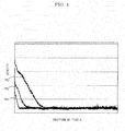
- FIG. 4 is a graph showing a relationship between the position and the density of the pixels in the input image of the book placed on the platen (the contact glass) in the opened wide state.
- the position of the pixels indicates a distance from the bind position as shown in FIG. 3 .
- a property M1 in FIG. 4 indicates one exemplary relationship between the position and the density of the pixels in the input image in a case where the book placed on the platen is pressed by a document cover (including an automatic document feeding device). In this case, the document cover considerably blocks off ambient light incident on the platen.
- a property M2 in FIG. 4 indicates one exemplary relationship between the position and the density of the pixels in the input image in a case where the book placed on the platen is pressed by hands of the user without pressing the book by the document cover (including the automatic document feeding device).
- the document cover does not block off the light incident on the platen.
- floating of the bind portion from the platen is small.
- a property M3 in FIG. 4 indicates one exemplary relationship between the position and the density of the pixels in the input image in a case where the book placed on the platen is pressed neither by the document cover (including the automatic document feeding device) nor by the hands of the user. In this case, the document cover does not block off the light incident on the platen. Moreover, in this case, because the book is pressed neither by the document cover nor the hands, the floating of the bind portion from the platen is large as compared to the cases of the properties M1 and M2.
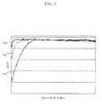
- FIGS. 5 and 6 are graphs used for explaining a relationship between the position of the pixels in the input image of the book placed on the platen in the opened wide state and the width shown in FIG. 3 .
- FIG. 6 is reverse of FIG. 5 upside down. That is, a width shown in FIG. 6 is obtained by subtracting the width shown in FIG. 5 from the maximum width (i.e., the width of the part where the book is in close contact with the contact glass).
- a property M1 in FIGS. 5 and 6 indicates one exemplary relationship between the position of the pixels and the width in the input image in a case where the book placed on the platen is pressed by the document cover (including the automatic document feeding device). In this case, because the book is pressed by the document cover, the floating of the bind portion from the platen is small and the width around the bind position is long.
- a property M2 in FIGS. 5 and 6 indicates one exemplary relationship between the position of the pixels and the width in the input image in a case where the book placed on the platen is pressed by hands of the user without pressing the book by the document cover (including the automatic document feeding device). In this case, because the book is pressed by the hands, the floating of the bind portion from the platen is slightly small and the width around the bind position is slightly long.
- a property M3 in FIGS. 5 and 6 indicates one exemplary relationship between the position of the pixels and the width in the input image in a case where the book placed on the platen is pressed neither by the document cover (including the automatic document feeding device) nor the hands of the user. In this case, because the book is pressed neither by the document cover nor the hands, the floating of the bind portion from the platen is large and the width around the bind position is short, as compared to the cases of properties M1 and M2.
- the density correcting part 14 corrects the density of each pixel within each line by input-output properties based on the value of the above-mentioned density correcting parameter.
- the input-output properties may be a linear function.
- FIG. 7 is a graph showing one exemplary input-output properties of the density correcting part 14 shown in FIG. 2 .
- the density correcting part 14 changes the input-output properties in accordance with the value of the density correcting parameter a .
- the maximum width is a maximum value of width of all lines of the input image
- the factor of k is a predetermined coefficient
- This input-output properties is used for converting an input density value within a high density region specified by the value of the density correcting parameter to an output density value within a density region wider than the high density region. That is, in the case of FIG. 7 , the high density region from the value a ( a > 0 %) of the density correcting parameter to 100 % is converted to a density region from 0 % to 100 %.
- the input-output properties makes the output density value be equal to or less than the input density value.
- the memory 3 is a volatile memory, such as a DRAM (Dynamic Random Access Memory).
- a memory area required for the processing of the image processing part 2 and others is suitably assured.
- the main control part 4 controls the scanner part 1, the image processing part 2, the memory 3 and the output part 5.
- the output part 5 outputs image data processed by the image processing part 2.
- the scanner part 1 When the user places the book on the platen of the scanner part 1 and carries out a predetermined manipulation, the scanner part 1 reads an image of the book and outputs data of the input image to the image processing part 2.
- the width specifying part 11 specifies a width of each line and specifies the above-mentioned maximum width of the input image.
- the bind portion region specifying part 13 specifies a bind portion region of the input image.
- the parameter value specifying part 12 specifies the value a of a density correcting parameter corresponding to the width of each line.
- the density correcting part 14 corrects density of pixels within the bind portion region among pixels belonging to each line by the input-output properties corresponding to the value a of the density correcting parameter of the line.
- the width specifying part 11 specifies the width between the both ends of the input image about each line of the input image of the book
- the parameter value specifying part 12 specifies the value of the density correcting parameter corresponding to the width specified by the width specifying part 11
- the density correcting part 14 corrects the density of each line on the basis of the value of the density correcting parameter specified by the parameter value specifying part 12.
- the density of the bind portion is automatically corrected to an appropriate density, it is possible to eliminate the noise of the bind portion without coercing the extra labor and the wasteful reading and copying of the image.
- the present disclosure is applicable to an image reading apparatus, such as a scanning machine, a copying machine and a multi-function peripheral.
Landscapes
- Engineering & Computer Science (AREA)
- Multimedia (AREA)
- Signal Processing (AREA)
- Facsimile Scanning Arrangements (AREA)
- Image Processing (AREA)
- Facsimile Image Signal Circuits (AREA)
Abstract
Description
- This application is based on and claims the benefit of priority from Japanese Patent application No.
2012-281763 filed on December 25, 2012 - The present disclosure relates to an image processing device and an image reading apparatus including the same.
- In an image reading apparatus, such as a copying machine and a scanner, when an image of a book, particularly a thick book having a large number of pages, is read, the book is placed on a platen in an opened state of a desired page and scanning is executed. At that time, if a bind portion of the book is floated from the platen, a noise of black pixels is generated at a part corresponding to the bind portion in a document image. Because such a noise is unneeded by a user, it is desirable to automatically eliminate the noise.
- In a certain image reading apparatus, the noise is eliminated in a simple process, such as a labeling process, by extracting a connected region of the black pixels. Such a manner poses no problem if a range corresponding to the noise region of the bind portion is a blank (i.e., a region containing no character information). However, if the significant information, such as characters and pictures, is contained in the region, the significant information may be eliminated together with the noise.
- Due to that, there is an image reading apparatus configured to determine a range in which a noise of a bind portion of a book is searched in an input image, to specify a noise region of the bind portion within the determined range, to separate the noise region from other information region, and to eliminate the separated noise region.
- In such a manner of the image reading apparatus, since it is difficult to completely separate the noise region of the bind portion from the other information region, intensity of elimination of the noise is selected by the user, and then, a parameter is finely adjusted.
- However, because the user is unable to readily understand how much the noise should be eliminated, the user is required to find a suitable setting by reading or copying an image by many times while changing the intensity of the elimination of the noise. As a result, extra labor and wasteful reading or copying of the image may be coerced.
- In accordance with an embodiment of the present disclosure, an image processing device includes a width specifying part, a parameter value specifying part, and a density correcting part. The width specifying part is configured to specify a width between both ends of an input image of a book about each line of the input image. The parameter value specifying part is configured to specify a value of a density correcting parameter corresponding to the width specified by the width specifying part. The density correcting part is configured to correct density of each line on the basis of the value of the density correcting parameter specified by the parameter value specifying part.
- In accordance with another embodiment of the present disclosure, an image reading apparatus includes an image processing device and a scanner part configured to read an input image from a book. The image processing device includes a width specifying part, a parameter value specifying part, and a density correcting part. The width specifying part is configured to specify a width between both ends of an input image of the book about one line of the input image. The parameter value specifying part is configured to specify a value of a density correcting parameter corresponding to the width specified by the width specifying part. The density correcting part is configured to correct density of each line on the basis of the value of the density correcting parameter specified by the parameter value specifying part.
- The above and other objects, features and advantages of the present disclosure will become more apparent from the following description when taken in conjunction with the attached drawings illustrating preferable and specific embodiment of the present disclosure.
-
-
FIG. 1 is a block diagram showing a configuration of an image reading apparatus according to an embodiment of the present disclosure. -
FIG. 2 is a block diagram showing a configuration of an image processing part in the image reading apparatus of the embodiment of the present disclosure. -
FIG. 3 is a schematic diagram showing one exemplary input image of a book read by the image reading apparatus of the embodiment of the present disclosure. -
FIG. 4 is a graph showing a relationship between position and density of pixels in the input image of the book placed on a platen (a contact glass) in an opened wide state in the image reading apparatus of the embodiment of the present disclosure. -
FIG. 5 is a graph showing a relationship between the position of the pixels in the input image of the book placed on the platen in the opened wide state and a width of the input image shown inFIG. 3 in the image reading apparatus of the embodiment of the present disclosure. -
FIG. 6 is a graph showing the relationship between the position of the pixels in the input image of the book placed on the platen in the opened wide state and the width of the input image shown inFIG. 3 in the image reading apparatus of the embodiment of the present disclosure. -
FIG. 7 is a graph showing one exemplary input-output properties of a density correcting part of the image processing part shown inFIG. 2 in the image reading apparatus of the embodiment of the present disclosure. - in the following, an embodiment of the present disclosure will be described with reference to the drawings.
-
FIG. 1 is a block diagram showing a configuration of an image reading apparatus according to the embodiment the present disclosure. The image reading apparatus shown inFIG. 1 includes ascanner part 1, animage processing part 2, amemory 3, amain control part 4, and anoutput part 5 which are connected with each other. - The
scanner part 1 is configured to optically read a page image of a document and to generate and output image data of the page image (i.e., an input image). The image data includes image information of each pixel, such as RGB values. - The
image processing part 2 is configured to execute predetermined processes on the image data of the input image. Theimage processing part 2 executes the predetermined processes on the image data outputted from thescanner part 1 or on image data on which previous processes has been executed on the image data outputted from thescanner part 1. Theimage processing part 2 writes the image data executed by the predetermined processing into a predetermined memory area in thememory 3. For example, theimage processing part 2 is composed of one or a plurality of ASICs (Application Specific Integrated Circuit). -
FIG. 2 is a block diagram showing a configuration of theimage processing part 2 shown inFIG. 1 , andFIG. 3 is a schematic diagram showing one exemplary input image of a book. - The
image processing part 2 includes awidth specifying part 11, a parametervalue specifying part 12, a bind portionregion specifying part 13, and adensity correcting part 14. - The
width specifying part 11 is configured to specify a width between both ends of the input image about each line of the input image of the book. A unit of the width may be a number of pixels or a ratio to a maximum width (i.e., a width of a part where the book is in close contact with the contact glass). For instance, thewidth specifying part 11 specifiesedges 101 from a distribution of density of the input image of the book and specifies a distance between two intersection points of one line and theedges 101 as a width. Alternatively, the width may be specified on the basis of other known techniques. - Incidentally, the input image of the book is what is read by the
scanner part 1 from the book placed on the platen in an opened wide state. - The parameter
value specifying part 12 is configured to specify a value of a density correcting parameter corresponding to the width specified by thewidth specifying part 11. - The bind portion
region specifying part 13 is configured to specify a region of the bind portion in the input image of the book. For example, the bind portion region may be specified as a region having the above-mentioned width shorter than the maximum width by a predetermined length or more, or may be specified, after a bind position is specified, as a region extending to a predetermined pixel position from the specified bind position. The bind portion region also may be specified on the basis of other known techniques. - The
density correcting part 14 corrects density of each line on the basis of the density correcting parameter specified by the parametervalue specifying part 12. In the embodiment, thedensity correcting part 14 corrects the density within the above-mentioned bind portion region and does not correct the density of the region other than the bind portion region. -
FIG. 4 is a graph showing a relationship between the position and the density of the pixels in the input image of the book placed on the platen (the contact glass) in the opened wide state. The position of the pixels indicates a distance from the bind position as shown inFIG. 3 . - A property M1 in
FIG. 4 indicates one exemplary relationship between the position and the density of the pixels in the input image in a case where the book placed on the platen is pressed by a document cover (including an automatic document feeding device). In this case, the document cover considerably blocks off ambient light incident on the platen. - A property M2 in
FIG. 4 indicates one exemplary relationship between the position and the density of the pixels in the input image in a case where the book placed on the platen is pressed by hands of the user without pressing the book by the document cover (including the automatic document feeding device). In this case, the document cover does not block off the light incident on the platen. Moreover, in this case, because the book is pressed by the hands, floating of the bind portion from the platen is small. - A property M3 in
FIG. 4 indicates one exemplary relationship between the position and the density of the pixels in the input image in a case where the book placed on the platen is pressed neither by the document cover (including the automatic document feeding device) nor by the hands of the user. In this case, the document cover does not block off the light incident on the platen. Moreover, in this case, because the book is pressed neither by the document cover nor the hands, the floating of the bind portion from the platen is large as compared to the cases of the properties M1 and M2. -
FIGS. 5 and6 are graphs used for explaining a relationship between the position of the pixels in the input image of the book placed on the platen in the opened wide state and the width shown inFIG. 3 .FIG. 6 is reverse ofFIG. 5 upside down. That is, a width shown inFIG. 6 is obtained by subtracting the width shown inFIG. 5 from the maximum width (i.e., the width of the part where the book is in close contact with the contact glass). - A property M1 in
FIGS. 5 and6 indicates one exemplary relationship between the position of the pixels and the width in the input image in a case where the book placed on the platen is pressed by the document cover (including the automatic document feeding device). In this case, because the book is pressed by the document cover, the floating of the bind portion from the platen is small and the width around the bind position is long. - A property M2 in
FIGS. 5 and6 indicates one exemplary relationship between the position of the pixels and the width in the input image in a case where the book placed on the platen is pressed by hands of the user without pressing the book by the document cover (including the automatic document feeding device). In this case, because the book is pressed by the hands, the floating of the bind portion from the platen is slightly small and the width around the bind position is slightly long. - A property M3 in
FIGS. 5 and6 indicates one exemplary relationship between the position of the pixels and the width in the input image in a case where the book placed on the platen is pressed neither by the document cover (including the automatic document feeding device) nor the hands of the user. In this case, because the book is pressed neither by the document cover nor the hands, the floating of the bind portion from the platen is large and the width around the bind position is short, as compared to the cases of properties M1 and M2. - As shown in
FIGS. 4 through 6 , it can be seen that there is a correlation between the relationship between the position and the density of the pixels and the relationship between the pixel position and the width. In the embodiment, by utilizing such a characteristic, a value of a density correcting parameter corresponding to the above-mentioned width is specified and density correction is executed on the basis of the value of the density correcting parameter, and accordingly, the density of a part having excessive density around the bind portion is suitably reduced. - In the embodiment, the
density correcting part 14 corrects the density of each pixel within each line by input-output properties based on the value of the above-mentioned density correcting parameter. In the embodiment, the input-output properties may be a linear function. -
FIG. 7 is a graph showing one exemplary input-output properties of thedensity correcting part 14 shown inFIG. 2 . For example, as shown inFIG. 7 , thedensity correcting part 14 changes the input-output properties in accordance with the value of the density correcting parameter a. In the case ofFIG. 7 , if the linear function of the input-output properties is presumed by a numerical expression of f(x) = P • x + Q (where, the variable of x is an input density value), the invariables of P and Q are determined by numerical expressions of P = -1/(a - 1) and Q = a/(a - 1) by using the density correcting parameter a. If x is equal to or less than a, the linear function results in f(x) = 0. - For example, with regard to a target line (a line to be corrected by the density correcting part 14), the value of the density correcting parameter a can be obtained from the following equation:

- Herein, the maximum width is a maximum value of width of all lines of the input image, and the factor of k is a predetermined coefficient.
- This input-output properties is used for converting an input density value within a high density region specified by the value of the density correcting parameter to an output density value within a density region wider than the high density region. That is, in the case of
FIG. 7 , the high density region from the value a (a > 0 %) of the density correcting parameter to 100 % is converted to a density region from 0 % to 100 %. - Furthermore, in the embodiment, the input-output properties makes the output density value be equal to or less than the input density value.
- As shown in
FIG. 1 , thememory 3 is a volatile memory, such as a DRAM (Dynamic Random Access Memory). In thememory 3, a memory area required for the processing of theimage processing part 2 and others is suitably assured. - The
main control part 4 controls thescanner part 1, theimage processing part 2, thememory 3 and theoutput part 5. - The
output part 5 outputs image data processed by theimage processing part 2. - Next, operations of the above-mentioned image reading apparatus will be described.
- When the user places the book on the platen of the
scanner part 1 and carries out a predetermined manipulation, thescanner part 1 reads an image of the book and outputs data of the input image to theimage processing part 2. - In the
image processing part 2, thewidth specifying part 11 specifies a width of each line and specifies the above-mentioned maximum width of the input image. The bind portionregion specifying part 13 specifies a bind portion region of the input image. - Subsequently, the parameter
value specifying part 12 specifies the value a of a density correcting parameter corresponding to the width of each line. - Then, the
density correcting part 14 corrects density of pixels within the bind portion region among pixels belonging to each line by the input-output properties corresponding to the value a of the density correcting parameter of the line. - As described above, according to the above-mentioned embodiment, the
width specifying part 11 specifies the width between the both ends of the input image about each line of the input image of the book, the parametervalue specifying part 12 specifies the value of the density correcting parameter corresponding to the width specified by thewidth specifying part 11, and thedensity correcting part 14 corrects the density of each line on the basis of the value of the density correcting parameter specified by the parametervalue specifying part 12. - Accordingly, because the density of the bind portion is automatically corrected to an appropriate density, it is possible to eliminate the noise of the bind portion without coercing the extra labor and the wasteful reading and copying of the image.
- While the above-mentioned embodiment illustrates preferable examples of the present disclosure, the present disclosure is not restricted by the embodiment, and the embodiment can be changed or modified without departing from the scope and spirit of the present disclosure.
- The present disclosure is applicable to an image reading apparatus, such as a scanning machine, a copying machine and a multi-function peripheral.
Claims (9)
- An image processor, comprising:a width specifying part configured to specify a width between both ends of an input image of a book about each line of the input image;a parameter value specifying part configured to specify a value of a density correcting parameter corresponding to the width specified by the width specifying part; anda density correcting part configured to correct density of each line on the basis of the value of the density correcting parameter specified by the parameter value specifying part.
- The image processor according to claim 1, wherein
the density correcting part corrects the density of each pixel within each line by input-output properties on the basis of the value of the density correcting parameter; and
the input-output properties is determined so as to convert an input density value within a high density region specified by the value of the density correcting parameter to an output density value within a density region wider than the high density region. - The image processor according to claim 2, wherein
the density correcting part utilizes the input-output properties making the output density value be equal to or less than the input density value. - The image processor according to any one of claims 1 to 3, further comprising:a bind portion region specifying part configured to specify a bind portion region in the input image of the book;wherein the density correcting part is configured to correct density within the bind portion region and not to correct density of a region other than the bind portion region.
- An image reading apparatus comprising:an image processing device; anda scanner part configured to read an input image from a book,wherein the image processing device includes:a width specifying part configured to specify a width between both ends of the input image of the book about each line of the input image;a parameter value specifying part configured to specify a value of a density correcting parameter corresponding to the width specified by the width specifying part; anda density correcting part configured to correct density of each line on the basis of the value of the density correcting parameter specified by the parameter value specifying part.
- The image reading apparatus according to claim 5, wherein
the density correcting part corrects density of each pixel within each line by input-output properties on the basis of the value of the density correcting parameter; and
the input-output properties is determined so as to convert an input density value within a high density region specified by the value of the density correcting parameter to an output density value within a density region wider than the high density region. - The image reading apparatus according to claim 6, wherein the density correcting part utilizes the input-output properties making the output density value be equal to or less than the input density value.
- The image reading apparatus according to any one of claims 5 to 7, further comprising:a bind portion region specifying part configured to specify a bind portion region in the input image of the book;wherein the density correcting part is configured to correct density within the bind portion region and not to correct density of a region other than the bind portion region.
- The image reading apparatus according to any one of claims 5 to 8, wherein
the parameter value specifying part obtains, on the basis of a width of a target line to be corrected by the density correcting part and a maximum width in which the book is in close contact with a contact glass of the scanner part, the density correcting parameter a by using a predetermined coefficient k with a numerical expression of a = (maximum width - width of target line) / maximum value * k; and
the density correcting part obtains the invariables of P and Q on the basis of the density correcting parameter a by numerical expressions of P = -1/(a - 1) and Q = a/(a - 1) and determines the input-output properties of f(x) regarding the input density value x by a linear function of f(x) = P · x + Q.
Applications Claiming Priority (1)
| Application Number | Priority Date | Filing Date | Title |
|---|---|---|---|
| JP2012281763A JP5777601B2 (en) | 2012-12-25 | 2012-12-25 | Image processing apparatus and image reading apparatus |
Publications (2)
| Publication Number | Publication Date |
|---|---|
| EP2750366A1 true EP2750366A1 (en) | 2014-07-02 |
| EP2750366B1 EP2750366B1 (en) | 2016-09-14 |
Family
ID=49724513
Family Applications (1)
| Application Number | Title | Priority Date | Filing Date |
|---|---|---|---|
| EP13196188.0A Not-in-force EP2750366B1 (en) | 2012-12-25 | 2013-12-09 | Image processing device and image reading apparatus |
Country Status (4)
| Country | Link |
|---|---|
| US (1) | US9019577B2 (en) |
| EP (1) | EP2750366B1 (en) |
| JP (1) | JP5777601B2 (en) |
| CN (1) | CN103905678B (en) |
Citations (4)
| Publication number | Priority date | Publication date | Assignee | Title |
|---|---|---|---|---|
| US5834762A (en) * | 1994-12-13 | 1998-11-10 | Minolta Co., Ltd. | Image reading apparatus and method |
| EP1032191A2 (en) * | 1999-02-23 | 2000-08-30 | Riso Kagaku Corporation | Method and apparatus for correcting degradation of book center image by image processing based on contour of book center image |
| JP2002033919A (en) * | 2000-07-14 | 2002-01-31 | Minolta Co Ltd | Reader |
| KR20110024318A (en) * | 2009-09-02 | 2011-03-09 | 심규철 | Scanner unit and scanning method |
Family Cites Families (7)
| Publication number | Priority date | Publication date | Assignee | Title |
|---|---|---|---|---|
| JPH05153363A (en) | 1991-11-28 | 1993-06-18 | Sanyo Electric Co Ltd | Image information processor |
| JP3425366B2 (en) * | 1998-06-30 | 2003-07-14 | シャープ株式会社 | Image correction device |
| JP2000354166A (en) * | 1999-06-11 | 2000-12-19 | Minolta Co Ltd | Image reader |
| JP3902364B2 (en) * | 1999-10-08 | 2007-04-04 | 株式会社リコー | Image forming apparatus |
| JP3860424B2 (en) * | 2001-02-28 | 2006-12-20 | 株式会社リコー | Image processing method, image processing apparatus, image processing program, and recording medium |
| JP3983721B2 (en) | 2003-07-31 | 2007-09-26 | 株式会社リコー | Image distortion correction apparatus, image reading apparatus, image forming apparatus, and program |
| JP2005115768A (en) * | 2003-10-09 | 2005-04-28 | Brother Ind Ltd | Image processing method, image processing apparatus, image forming apparatus, and image processing system |
-
2012
- 2012-12-25 JP JP2012281763A patent/JP5777601B2/en not_active Expired - Fee Related
-
2013
- 2013-12-09 EP EP13196188.0A patent/EP2750366B1/en not_active Not-in-force
- 2013-12-10 CN CN201310670371.6A patent/CN103905678B/en not_active Expired - Fee Related
- 2013-12-20 US US14/137,107 patent/US9019577B2/en not_active Expired - Fee Related
Patent Citations (4)
| Publication number | Priority date | Publication date | Assignee | Title |
|---|---|---|---|---|
| US5834762A (en) * | 1994-12-13 | 1998-11-10 | Minolta Co., Ltd. | Image reading apparatus and method |
| EP1032191A2 (en) * | 1999-02-23 | 2000-08-30 | Riso Kagaku Corporation | Method and apparatus for correcting degradation of book center image by image processing based on contour of book center image |
| JP2002033919A (en) * | 2000-07-14 | 2002-01-31 | Minolta Co Ltd | Reader |
| KR20110024318A (en) * | 2009-09-02 | 2011-03-09 | 심규철 | Scanner unit and scanning method |
Also Published As
| Publication number | Publication date |
|---|---|
| CN103905678B (en) | 2016-08-17 |
| US20140177015A1 (en) | 2014-06-26 |
| JP2014127777A (en) | 2014-07-07 |
| CN103905678A (en) | 2014-07-02 |
| EP2750366B1 (en) | 2016-09-14 |
| JP5777601B2 (en) | 2015-09-09 |
| US9019577B2 (en) | 2015-04-28 |
Similar Documents
| Publication | Publication Date | Title |
|---|---|---|
| US8611661B2 (en) | OCR multi-resolution method and apparatus | |
| US8922842B2 (en) | Controlling device for controlling scan performing unit | |
| US9013755B2 (en) | Image processing device for determining output resolution and converting scan data into image data indicating output resolution | |
| US9558433B2 (en) | Image processing apparatus generating partially erased image data and supplementary data supplementing partially erased image data | |
| US8928950B2 (en) | Controlling device for controlling scan performing unit | |
| US9794435B1 (en) | System and method for arranging scanned images | |
| US10860644B2 (en) | Image processing apparatus | |
| US9019577B2 (en) | Image processing device and image reading apparatus | |
| US10148848B2 (en) | Image reading apparatus and image forming apparatus | |
| US10609249B2 (en) | Scanner and scanning control program which outputs an original image and an extracted image in a single file | |
| US8967479B2 (en) | Image processing apparatus and method for converting a color barcode into a monochrome barcode | |
| US20150022865A1 (en) | Image processing apparatus | |
| US20140293354A1 (en) | Image processing apparatus and image processing method capable of copying document | |
| US9400926B2 (en) | Image processing apparatus, image processing method, and non-transitory computer readable medium | |
| US20150261486A1 (en) | Image processing apparatus and image processing method | |
| US9498980B2 (en) | Printing apparatus, printing method and image processing apparatus | |
| JP2006279107A (en) | Image processor and processing method | |
| JP4692169B2 (en) | Image processing apparatus, image processing method, program, and recording medium | |
| JP5871116B2 (en) | Image processing apparatus, method, and program | |
| US20190012757A1 (en) | Image processing apparatus and image processing method | |
| CN110929480A (en) | Document editing method and device, computer storage medium and terminal | |
| JP2009278233A (en) | Image processor and image processing method | |
| JP2011193173A (en) | Image processing apparatus, program, and recording medium | |
| JP2013009378A (en) | Image processing apparatus, image processing method, computer program, and memory medium |
Legal Events
| Date | Code | Title | Description |
|---|---|---|---|
| 17P | Request for examination filed |
Effective date: 20131209 |
|
| AK | Designated contracting states |
Kind code of ref document: A1 Designated state(s): AL AT BE BG CH CY CZ DE DK EE ES FI FR GB GR HR HU IE IS IT LI LT LU LV MC MK MT NL NO PL PT RO RS SE SI SK SM TR |
|
| AX | Request for extension of the european patent |
Extension state: BA ME |
|
| PUAI | Public reference made under article 153(3) epc to a published international application that has entered the european phase |
Free format text: ORIGINAL CODE: 0009012 |
|
| R17P | Request for examination filed (corrected) |
Effective date: 20141230 |
|
| RBV | Designated contracting states (corrected) |
Designated state(s): AL AT BE BG CH CY CZ DE DK EE ES FI FR GB GR HR HU IE IS IT LI LT LU LV MC MK MT NL NO PL PT RO RS SE SI SK SM TR |
|
| 17Q | First examination report despatched |
Effective date: 20160510 |
|
| GRAP | Despatch of communication of intention to grant a patent |
Free format text: ORIGINAL CODE: EPIDOSNIGR1 |
|
| INTG | Intention to grant announced |
Effective date: 20160623 |
|
| GRAS | Grant fee paid |
Free format text: ORIGINAL CODE: EPIDOSNIGR3 |
|
| GRAA | (expected) grant |
Free format text: ORIGINAL CODE: 0009210 |
|
| AK | Designated contracting states |
Kind code of ref document: B1 Designated state(s): AL AT BE BG CH CY CZ DE DK EE ES FI FR GB GR HR HU IE IS IT LI LT LU LV MC MK MT NL NO PL PT RO RS SE SI SK SM TR |
|
| REG | Reference to a national code |
Ref country code: GB Ref legal event code: FG4D |
|
| REG | Reference to a national code |
Ref country code: CH Ref legal event code: EP |
|
| REG | Reference to a national code |
Ref country code: IE Ref legal event code: FG4D |
|
| REG | Reference to a national code |
Ref country code: AT Ref legal event code: REF Ref document number: 830105 Country of ref document: AT Kind code of ref document: T Effective date: 20161015 |
|
| REG | Reference to a national code |
Ref country code: DE Ref legal event code: R096 Ref document number: 602013011433 Country of ref document: DE |
|
| REG | Reference to a national code |
Ref country code: FR Ref legal event code: PLFP Year of fee payment: 4 |
|
| REG | Reference to a national code |
Ref country code: LT Ref legal event code: MG4D |
|
| REG | Reference to a national code |
Ref country code: NL Ref legal event code: MP Effective date: 20160914 |
|
| PG25 | Lapsed in a contracting state [announced via postgrant information from national office to epo] |
Ref country code: HR Free format text: LAPSE BECAUSE OF FAILURE TO SUBMIT A TRANSLATION OF THE DESCRIPTION OR TO PAY THE FEE WITHIN THE PRESCRIBED TIME-LIMIT Effective date: 20160914 Ref country code: FI Free format text: LAPSE BECAUSE OF FAILURE TO SUBMIT A TRANSLATION OF THE DESCRIPTION OR TO PAY THE FEE WITHIN THE PRESCRIBED TIME-LIMIT Effective date: 20160914 Ref country code: NO Free format text: LAPSE BECAUSE OF FAILURE TO SUBMIT A TRANSLATION OF THE DESCRIPTION OR TO PAY THE FEE WITHIN THE PRESCRIBED TIME-LIMIT Effective date: 20161214 Ref country code: LT Free format text: LAPSE BECAUSE OF FAILURE TO SUBMIT A TRANSLATION OF THE DESCRIPTION OR TO PAY THE FEE WITHIN THE PRESCRIBED TIME-LIMIT Effective date: 20160914 Ref country code: RS Free format text: LAPSE BECAUSE OF FAILURE TO SUBMIT A TRANSLATION OF THE DESCRIPTION OR TO PAY THE FEE WITHIN THE PRESCRIBED TIME-LIMIT Effective date: 20160914 |
|
| REG | Reference to a national code |
Ref country code: AT Ref legal event code: MK05 Ref document number: 830105 Country of ref document: AT Kind code of ref document: T Effective date: 20160914 |
|
| PG25 | Lapsed in a contracting state [announced via postgrant information from national office to epo] |
Ref country code: SE Free format text: LAPSE BECAUSE OF FAILURE TO SUBMIT A TRANSLATION OF THE DESCRIPTION OR TO PAY THE FEE WITHIN THE PRESCRIBED TIME-LIMIT Effective date: 20160914 Ref country code: LV Free format text: LAPSE BECAUSE OF FAILURE TO SUBMIT A TRANSLATION OF THE DESCRIPTION OR TO PAY THE FEE WITHIN THE PRESCRIBED TIME-LIMIT Effective date: 20160914 Ref country code: GR Free format text: LAPSE BECAUSE OF FAILURE TO SUBMIT A TRANSLATION OF THE DESCRIPTION OR TO PAY THE FEE WITHIN THE PRESCRIBED TIME-LIMIT Effective date: 20161215 Ref country code: NL Free format text: LAPSE BECAUSE OF FAILURE TO SUBMIT A TRANSLATION OF THE DESCRIPTION OR TO PAY THE FEE WITHIN THE PRESCRIBED TIME-LIMIT Effective date: 20160914 |
|
| PG25 | Lapsed in a contracting state [announced via postgrant information from national office to epo] |
Ref country code: RO Free format text: LAPSE BECAUSE OF FAILURE TO SUBMIT A TRANSLATION OF THE DESCRIPTION OR TO PAY THE FEE WITHIN THE PRESCRIBED TIME-LIMIT Effective date: 20160914 Ref country code: EE Free format text: LAPSE BECAUSE OF FAILURE TO SUBMIT A TRANSLATION OF THE DESCRIPTION OR TO PAY THE FEE WITHIN THE PRESCRIBED TIME-LIMIT Effective date: 20160914 |
|
| PG25 | Lapsed in a contracting state [announced via postgrant information from national office to epo] |
Ref country code: IS Free format text: LAPSE BECAUSE OF FAILURE TO SUBMIT A TRANSLATION OF THE DESCRIPTION OR TO PAY THE FEE WITHIN THE PRESCRIBED TIME-LIMIT Effective date: 20170114 Ref country code: BG Free format text: LAPSE BECAUSE OF FAILURE TO SUBMIT A TRANSLATION OF THE DESCRIPTION OR TO PAY THE FEE WITHIN THE PRESCRIBED TIME-LIMIT Effective date: 20161214 Ref country code: SM Free format text: LAPSE BECAUSE OF FAILURE TO SUBMIT A TRANSLATION OF THE DESCRIPTION OR TO PAY THE FEE WITHIN THE PRESCRIBED TIME-LIMIT Effective date: 20160914 Ref country code: PL Free format text: LAPSE BECAUSE OF FAILURE TO SUBMIT A TRANSLATION OF THE DESCRIPTION OR TO PAY THE FEE WITHIN THE PRESCRIBED TIME-LIMIT Effective date: 20160914 Ref country code: BE Free format text: LAPSE BECAUSE OF FAILURE TO SUBMIT A TRANSLATION OF THE DESCRIPTION OR TO PAY THE FEE WITHIN THE PRESCRIBED TIME-LIMIT Effective date: 20160914 Ref country code: ES Free format text: LAPSE BECAUSE OF FAILURE TO SUBMIT A TRANSLATION OF THE DESCRIPTION OR TO PAY THE FEE WITHIN THE PRESCRIBED TIME-LIMIT Effective date: 20160914 Ref country code: PT Free format text: LAPSE BECAUSE OF FAILURE TO SUBMIT A TRANSLATION OF THE DESCRIPTION OR TO PAY THE FEE WITHIN THE PRESCRIBED TIME-LIMIT Effective date: 20170116 Ref country code: CZ Free format text: LAPSE BECAUSE OF FAILURE TO SUBMIT A TRANSLATION OF THE DESCRIPTION OR TO PAY THE FEE WITHIN THE PRESCRIBED TIME-LIMIT Effective date: 20160914 Ref country code: SK Free format text: LAPSE BECAUSE OF FAILURE TO SUBMIT A TRANSLATION OF THE DESCRIPTION OR TO PAY THE FEE WITHIN THE PRESCRIBED TIME-LIMIT Effective date: 20160914 Ref country code: AT Free format text: LAPSE BECAUSE OF FAILURE TO SUBMIT A TRANSLATION OF THE DESCRIPTION OR TO PAY THE FEE WITHIN THE PRESCRIBED TIME-LIMIT Effective date: 20160914 |
|
| REG | Reference to a national code |
Ref country code: DE Ref legal event code: R097 Ref document number: 602013011433 Country of ref document: DE |
|
| PG25 | Lapsed in a contracting state [announced via postgrant information from national office to epo] |
Ref country code: IT Free format text: LAPSE BECAUSE OF FAILURE TO SUBMIT A TRANSLATION OF THE DESCRIPTION OR TO PAY THE FEE WITHIN THE PRESCRIBED TIME-LIMIT Effective date: 20160914 |
|
| PLBE | No opposition filed within time limit |
Free format text: ORIGINAL CODE: 0009261 |
|
| STAA | Information on the status of an ep patent application or granted ep patent |
Free format text: STATUS: NO OPPOSITION FILED WITHIN TIME LIMIT |
|
| PG25 | Lapsed in a contracting state [announced via postgrant information from national office to epo] |
Ref country code: DK Free format text: LAPSE BECAUSE OF FAILURE TO SUBMIT A TRANSLATION OF THE DESCRIPTION OR TO PAY THE FEE WITHIN THE PRESCRIBED TIME-LIMIT Effective date: 20160914 |
|
| REG | Reference to a national code |
Ref country code: CH Ref legal event code: PL |
|
| 26N | No opposition filed |
Effective date: 20170615 |
|
| PG25 | Lapsed in a contracting state [announced via postgrant information from national office to epo] |
Ref country code: MC Free format text: LAPSE BECAUSE OF FAILURE TO SUBMIT A TRANSLATION OF THE DESCRIPTION OR TO PAY THE FEE WITHIN THE PRESCRIBED TIME-LIMIT Effective date: 20160914 |
|
| REG | Reference to a national code |
Ref country code: IE Ref legal event code: MM4A |
|
| PG25 | Lapsed in a contracting state [announced via postgrant information from national office to epo] |
Ref country code: CH Free format text: LAPSE BECAUSE OF NON-PAYMENT OF DUE FEES Effective date: 20161231 Ref country code: LU Free format text: LAPSE BECAUSE OF NON-PAYMENT OF DUE FEES Effective date: 20161209 Ref country code: LI Free format text: LAPSE BECAUSE OF NON-PAYMENT OF DUE FEES Effective date: 20161231 |
|
| REG | Reference to a national code |
Ref country code: FR Ref legal event code: PLFP Year of fee payment: 5 |
|
| PG25 | Lapsed in a contracting state [announced via postgrant information from national office to epo] |
Ref country code: SI Free format text: LAPSE BECAUSE OF FAILURE TO SUBMIT A TRANSLATION OF THE DESCRIPTION OR TO PAY THE FEE WITHIN THE PRESCRIBED TIME-LIMIT Effective date: 20160914 Ref country code: IE Free format text: LAPSE BECAUSE OF NON-PAYMENT OF DUE FEES Effective date: 20161209 |
|
| PG25 | Lapsed in a contracting state [announced via postgrant information from national office to epo] |
Ref country code: HU Free format text: LAPSE BECAUSE OF FAILURE TO SUBMIT A TRANSLATION OF THE DESCRIPTION OR TO PAY THE FEE WITHIN THE PRESCRIBED TIME-LIMIT; INVALID AB INITIO Effective date: 20131209 |
|
| PG25 | Lapsed in a contracting state [announced via postgrant information from national office to epo] |
Ref country code: CY Free format text: LAPSE BECAUSE OF FAILURE TO SUBMIT A TRANSLATION OF THE DESCRIPTION OR TO PAY THE FEE WITHIN THE PRESCRIBED TIME-LIMIT Effective date: 20160914 Ref country code: MK Free format text: LAPSE BECAUSE OF FAILURE TO SUBMIT A TRANSLATION OF THE DESCRIPTION OR TO PAY THE FEE WITHIN THE PRESCRIBED TIME-LIMIT Effective date: 20160914 |
|
| PG25 | Lapsed in a contracting state [announced via postgrant information from national office to epo] |
Ref country code: MT Free format text: LAPSE BECAUSE OF NON-PAYMENT OF DUE FEES Effective date: 20161209 |
|
| PG25 | Lapsed in a contracting state [announced via postgrant information from national office to epo] |
Ref country code: AL Free format text: LAPSE BECAUSE OF FAILURE TO SUBMIT A TRANSLATION OF THE DESCRIPTION OR TO PAY THE FEE WITHIN THE PRESCRIBED TIME-LIMIT Effective date: 20160914 Ref country code: TR Free format text: LAPSE BECAUSE OF FAILURE TO SUBMIT A TRANSLATION OF THE DESCRIPTION OR TO PAY THE FEE WITHIN THE PRESCRIBED TIME-LIMIT Effective date: 20160914 |
|
| PGFP | Annual fee paid to national office [announced via postgrant information from national office to epo] |
Ref country code: DE Payment date: 20191126 Year of fee payment: 7 |
|
| PGFP | Annual fee paid to national office [announced via postgrant information from national office to epo] |
Ref country code: FR Payment date: 20191115 Year of fee payment: 7 |
|
| PGFP | Annual fee paid to national office [announced via postgrant information from national office to epo] |
Ref country code: GB Payment date: 20191206 Year of fee payment: 7 |
|
| REG | Reference to a national code |
Ref country code: DE Ref legal event code: R119 Ref document number: 602013011433 Country of ref document: DE |
|
| GBPC | Gb: european patent ceased through non-payment of renewal fee |
Effective date: 20201209 |
|
| PG25 | Lapsed in a contracting state [announced via postgrant information from national office to epo] |
Ref country code: FR Free format text: LAPSE BECAUSE OF NON-PAYMENT OF DUE FEES Effective date: 20201231 |
|
| PG25 | Lapsed in a contracting state [announced via postgrant information from national office to epo] |
Ref country code: DE Free format text: LAPSE BECAUSE OF NON-PAYMENT OF DUE FEES Effective date: 20210701 Ref country code: GB Free format text: LAPSE BECAUSE OF NON-PAYMENT OF DUE FEES Effective date: 20201209 |