EP2750285A2 - Switching Process and Associated Control Device - Google Patents
Switching Process and Associated Control Device Download PDFInfo
- Publication number
- EP2750285A2 EP2750285A2 EP13197676.3A EP13197676A EP2750285A2 EP 2750285 A2 EP2750285 A2 EP 2750285A2 EP 13197676 A EP13197676 A EP 13197676A EP 2750285 A2 EP2750285 A2 EP 2750285A2
- Authority
- EP
- European Patent Office
- Prior art keywords
- electric machine
- asd
- stage
- electrical network
- voltage
- Prior art date
- Legal status (The legal status is an assumption and is not a legal conclusion. Google has not performed a legal analysis and makes no representation as to the accuracy of the status listed.)
- Granted
Links
Images

Classifications
-
- H—ELECTRICITY
- H02—GENERATION; CONVERSION OR DISTRIBUTION OF ELECTRIC POWER
- H02P—CONTROL OR REGULATION OF ELECTRIC MOTORS, ELECTRIC GENERATORS OR DYNAMO-ELECTRIC CONVERTERS; CONTROLLING TRANSFORMERS, REACTORS OR CHOKE COILS
- H02P1/00—Arrangements for starting electric motors or dynamo-electric converters
- H02P1/16—Arrangements for starting electric motors or dynamo-electric converters for starting dynamo-electric motors or dynamo-electric converters
- H02P1/46—Arrangements for starting electric motors or dynamo-electric converters for starting dynamo-electric motors or dynamo-electric converters for starting an individual synchronous motor
- H02P1/50—Arrangements for starting electric motors or dynamo-electric converters for starting dynamo-electric motors or dynamo-electric converters for starting an individual synchronous motor by changing over from asynchronous to synchronous operation
-
- H—ELECTRICITY
- H02—GENERATION; CONVERSION OR DISTRIBUTION OF ELECTRIC POWER
- H02P—CONTROL OR REGULATION OF ELECTRIC MOTORS, ELECTRIC GENERATORS OR DYNAMO-ELECTRIC CONVERTERS; CONTROLLING TRANSFORMERS, REACTORS OR CHOKE COILS
- H02P1/00—Arrangements for starting electric motors or dynamo-electric converters
- H02P1/16—Arrangements for starting electric motors or dynamo-electric converters for starting dynamo-electric motors or dynamo-electric converters
- H02P1/26—Arrangements for starting electric motors or dynamo-electric converters for starting dynamo-electric motors or dynamo-electric converters for starting an individual polyphase induction motor
-
- H—ELECTRICITY
- H02—GENERATION; CONVERSION OR DISTRIBUTION OF ELECTRIC POWER
- H02P—CONTROL OR REGULATION OF ELECTRIC MOTORS, ELECTRIC GENERATORS OR DYNAMO-ELECTRIC CONVERTERS; CONTROLLING TRANSFORMERS, REACTORS OR CHOKE COILS
- H02P21/00—Arrangements or methods for the control of electric machines by vector control, e.g. by control of field orientation
- H02P21/34—Arrangements for starting
-
- H—ELECTRICITY
- H02—GENERATION; CONVERSION OR DISTRIBUTION OF ELECTRIC POWER
- H02P—CONTROL OR REGULATION OF ELECTRIC MOTORS, ELECTRIC GENERATORS OR DYNAMO-ELECTRIC CONVERTERS; CONTROLLING TRANSFORMERS, REACTORS OR CHOKE COILS
- H02P27/00—Arrangements or methods for the control of AC motors characterised by the kind of supply voltage
- H02P27/04—Arrangements or methods for the control of AC motors characterised by the kind of supply voltage using variable-frequency supply voltage, e.g. inverter or converter supply voltage
- H02P27/06—Arrangements or methods for the control of AC motors characterised by the kind of supply voltage using variable-frequency supply voltage, e.g. inverter or converter supply voltage using DC to AC converters or inverters
-
- H—ELECTRICITY
- H02—GENERATION; CONVERSION OR DISTRIBUTION OF ELECTRIC POWER
- H02P—CONTROL OR REGULATION OF ELECTRIC MOTORS, ELECTRIC GENERATORS OR DYNAMO-ELECTRIC CONVERTERS; CONTROLLING TRANSFORMERS, REACTORS OR CHOKE COILS
- H02P4/00—Arrangements specially adapted for regulating or controlling the speed or torque of electric motors that can be connected to two or more different electric power supplies
Definitions
- the invention relates to a process of switching the power supply of an electric machine operating with alternating current between a power supply from an adjustable speed drive (ASD) and an electrical network.
- the invention also relates to a device for controlling the power supply of an associated electric machine.
- An electric machine converts electrical energy into mechanical energy.
- An electric machine is composed primarily of a motor.
- speed requirements are specific to the motor of the electric machine. This is the case particularly in the field of petroleum or gas compression. In such cases, it is desirable that the power supply to the motor can be rapidly switched from an electrical network to an adjustable speed drive or vice versa.
- An adjustable speed drive is especially suitable for starting the motor. Once it has been started, the motor must be powered by the electrical network, and moreover through an ASD. This requires the voltages supplied by the ASD and the network to be synchronised. This serves to prevent surges in the voltage or the current at the moment of switching, which can be detrimental to the motor of the electric machine.
- this synchronisation is achieved by a synchronisation device composed of a synchronisation unit and a synchro-check relay.
- a synchro-check relay is an apparatus that measures the amplitude and the phase difference between the voltage provided by the adjustable speed drive and the network voltage. The synchro-check can verify the conformity of the amplitude and the phase measured against a synchronisation criterion.
- the synchronisation is activated.
- This unit sends instructions to an adjustable speed drive controller so that the latter can correct the measured difference.
- the instructions are generally sent in the form of electrical impulses.
- the acceleration stage When this technique is used for starting, the acceleration stage lasts as long as 10 seconds and the synchronisation stage is active for 20 seconds. Thus, the overall process takes 30 seconds. This is long for certain ASDs that supply the motor. In certain cases, this period is long enough that the heating of the adjustable speed drive requires a cooling by water or oversizing.
- the process includes a stage that determines the required rotary speed for the electrical machine, as well as the synchronisation of the phase and amplitude of the voltage supplied by the ASD with the voltage supplied by the electrical network.
- the synchronisation stage includes a step that measures the voltage supplied by the ASD and the voltage supplied by the electrical network and calculates the signals representing, respectively, the amplitude difference and the phase difference between the two measured voltages.
- the process includes a step that determines an ideal flux for the electric machine.
- the synchronisation stage also includes a step that generates a control signal at the voltage of the ASD from the ideal flux. The signal representing the difference of the calculated amplitude is then added to this.
- the process comprises one or more of the following characteristics, taken separately or in any combination that is technically possible:
- this invention also relates to a device to control the voltage supply to an alternating current electric machine, where the electric machine can be powered by a ASD and an electrical network, where the device comprises a sensor to measure the voltage supplied by the electrical network and a control device that can activate the switching process as described above.
- the direction of the current is defined as being upstream-downstream.
- the electrical system 10 in Figure 1 comprises a supply 12 of electrical voltage, a device 14 for controlling the electrical supply 12 and an alternating current machine 16.
- the electrical supply 12 is connected to the electrical machine 16 by a connection 17.
- the electrical supply 12 comprises an input 18 and an output 20.
- the input is connected to the electrical network 22.
- the electrical network 22 is able to supply voltage and functions at a frequency known as the network frequency.
- the voltage supplied by the electrical network 22 is a three-phase voltage.
- the electrical supply 12 contains two circuits, 24 and 26, connecting the input 18 to the output 20.
- the first circuit 24 comprises just one switch 28.
- This switch will be referred to below as the network switch 28.
- the network switch 28 has an open position, in which the input 18 and the output 20 are not connected via the first circuit 24, and a closed position, in which the input 18 and the output 20 are in direct electrical contact. In this latter case, the output 20 is connected to the electrical network 22.
- the second circuit comprises, in series, a separating transformer 30, an adjustable speed drive (ASD) 32, and a switch 34.
- ASD adjustable speed drive
- the transformer 30 is designed in such a manner that it brings about an effective separation between its primary circuit or circuits on one hand and its secondary circuit or circuits on the other.
- the ASD 32 is capable of starting an alternating current electric machine 16.
- the switch 34 of the second circuit 26 will be referred to below as the ASD switch 34.
- the ASD switch 34 has an open position in which the ASD 32 and the output 20 of the power supply 12 are not connected via the second circuit 26 and a closed position in which the ASD 32 and the output 20 of the power supply 12 are in direct electrical contact.
- the power supply 12 is thus able to operate according to three configurations.
- the power supply 12 is able to deliver voltage through the electrical network 22 on its own.
- the network switch 28 is closed and the ASD switch 34 is open.
- the power supply 12 is able to deliver voltage through the ASD 32 on its own.
- the network switch 28 is open and the ASD switch 34 is closed.
- the power supply 12 is able to deliver voltage through the electrical network 22 and the ASD 32.
- the two switches 28 and 34 are closed.
- the device 14 for controlling the electrical supply 12 comprises a flux estimator 36 for the electric machine 16, a speed measuring sensor or estimator 38 for the electric machine 16, two sensors numbered 40 and 42 for measuring the voltage, and a controller 44.
- the flux estimator 36 can estimate the flux by measuring the voltage and the current levels of the electric machine 16 regardless of the nature of the power supply 12 of the electric machine 16 (through the electrical network 22 and/or through the ASD 32).
- the speed measuring sensor 38 of the electric machine 16 is capable of measuring or estimating the speed of the electric machine 16.
- One sensor 40 of the two voltage measuring sensors (40 and 42) is capable of measuring the voltage of the electrical network 22 upstream of the network switch 28.
- the other voltage measuring sensor 42 is capable of measuring the voltage between the ASD 32 and the ASD switch 34.
- the flux estimator 36 and the three measuring sensors 38, 40, and 42 are connected to the controller 44.
- the controller 44 is capable of controlling the voltage of the ASD 32 and of opening and closing the two switches 28 and 34. This control capacity is shown schematically in Figure 1 by dotted lines 48.
- controller 44 is capable of switching the power supply 12 of an electric machine 16 between a power supply by the ASD 32 and the electrical network 22.
- the process includes a stage 100 for determining an ideal speed of rotation for an electric machine 16.
- the ideal speed of rotation is chosen as being equal to the speed of rotation associated with the operating frequency of the electrical network 22.
- the ideal speed of rotation is chosen as being equal to the nominal speed of the electric machine 16.
- the process includes a stage 102 for determining an ideal flux for the electric machine 16.
- the ideal flux is chosen as being the nominal flux of the electric machine 16.
- the motor When starting, the motor is initially stationary and the requirement is that the motor should be at the ideal speed of rotation while being supplied with voltage by the electrical network 22.
- stage 104 which sends an appropriate voltage command to the ASD 32 through the controller 44.
- the process thus includes a stage 106 for measuring the speed of rotation of the electric machine 16.
- a stage 108 is activated to synchronise the phase and amplitude of the voltage delivered by the ASD 32 with the voltage delivered by the electrical network 22.
- the predetermined value is less than 100% in order to ensure that the synchronisation stage 108 commences before the electric machine 16 achieves its ideal speed of rotation.
- the synchronisation stage 108 is activated if the speed of the electric machine 16 continues to increase.
- the predetermined value is equal to about 90%, preferably about 95%, or even more preferably about 96%.
- the synchronisation stage 108 includes a stage 110 which measures, by the voltage sensors 40 and 42, the voltages delivered by the ASD 32 and by the electrical network 22.
- the synchronisation stage 108 includes a stage 112 to calculate a signal representing the phase error between the voltages delivered by the ASD 32 and the electrical network 22.
- the signal representing the phase error is the phase difference between the voltage delivered by the ASD 32 and the voltage of the electrical network 22.
- the synchronisation stage 108 comprises a stage 114 to calculate a signal representing the amplitude error between the voltage delivered by the ASD 32 and the electrical network 22.
- the signal representing the amplitude error is the difference in amplitude between the voltage delivered by the ASD 32 and the voltage of the electrical network 22.
- the synchronisation stage 108 thus includes a stage 116 to generate a control signal for the ASD 32 on the basis of two signals calculated from the ideal speed of rotation and from the ideal flux.
- control signal is generated from two totals: one is the total of the ideal flux with the signal representing the amplitude in error, and the other is the total of the ideal speed of rotation with the signal representing the phase error.
- generation is set in motion by a method of "vector control” or “field-oriented control”.
- vector control method allows the speed and the flux of the electric machine 16 to be controlled by controlling the voltage applied to the ASD 32.
- PWM pulse width modulation
- the synchronisation stage is repeated in the event that two successive conditions are not satisfied. This is illustrated by the test 118 in the flowchart in Figure 2 and by the arrow 120.
- the two conditions are the synchronisation conditions with values bordering on the absolute value of the signals representing the phase and amplitude value.
- the absolute value of the signal representing the phase error is compared to about 2 degrees.
- the absolute value of the signal representing the amplitude value is compared to about 2% of the voltage delivered by the electrical network 22.
- the synchronisation stage 108 is completed and the process includes a stage 122, which sends a closing command to the network switch 28 by the controller 44.
- Stage 122 which sends the closing command, generally takes place very soon after the electric machine 16 has reached its ideal speed of rotation. Typically, it takes place in less than 3 seconds.
- the network switch 28 is closed as a result of the command sent by the controller 44 to the sending stage 122, the electric machine 16 is supplied simultaneously by the ASD 32 and the electrical network 22.
- the ASD 32 phase is served by the phase of the electrical network 22.
- the locking is carried out by a locking phase or loop controlled by the phase (this is also referred to by the acronym PLL for "Phase-Locked Loop”).
- the process thus includes a stage 124 for controlling the voltage of the ASD 32 to reduce the voltage and the current delivered by the ASD 32.
- the process includes a stage 126, in which a command is sent to the controller 44 to open the ASD switch 34.
- the predetermined threshold value is chosen in such a way that when the switch is opened, the ASD 32 delivers a low-amplitude current.
- the predetermined threshold value corresponds to about 5% of the value of the current delivered by the ASD 32 before stage 124, which controls the voltage of the ASD 32 in order to reduce the level of current delivered by the ASD 32.
- the predetermined threshold value can be equal to a fixed value. By way of illustration, this value is equal to about 5% of the nominal current.
- the power supply 12 has to be switched from a configuration where the voltage is supplied by the electrical network on its own (ASD switch 34 open and network switch 28 closed) to a configuration where the voltage is supplied by the ASD 32 on its own (ASD switch 34 closed and network switch 28 open).
- the process includes a stage 200 for measuring the speed of rotation of the electric machine 16.
- the process includes a stage 202 for determining an ideal speed of rotation for the electric machine 16.
- This stage 202 for determining an ideal speed of rotation is activated by choosing the measured speed of rotation as the ideal speed of rotation.
- the process includes a stage 204 for measuring the speed of rotation of the electric machine 16 by the flux estimator 36.
- the process includes a stage 206 for determining an ideal flux for the electric machine 16.
- This stage 206 for determining an ideal flux is activated by choosing the estimated flux as the ideal flux.
- the process comprises a synchronisation stage 208 identical to the synchronisation stage 108 described above with reference to Figure 2 .
- the synchronisation stage 208 is repeated if the two successive synchronisation conditions similar to those in the test 118 of the process described above are not satisfied. This is illustrated by the test 210 and the arrow 212.
- the synchronisation stage 208 is completed and the process includes a stage 214, in which a command is sent by the controller 44 to close the ASD switch 34.
- the electric machine 16 is supplied simultaneously by the ASD 32 and the electrical network 22.
- the ASD 32 phase is served by the phase of the electrical network 22.
- the locking is carried out by a locking phase or loop controlled by the phase (this is also referred to by the acronym PLL for "Phase-Locked Loop”).
- the process thus includes a stage 216 for controlling the voltage of the ASD 32 to reduce the current delivered by the electrical network 22 to the electric machine 16.
- the process includes a stage 218, in which a command is sent by the controller 44 to open the network switch 28.
- the predetermined threshold value is chosen in such a way that when the network switch 28 is opened, the electrical network 22 delivers a low-amplitude current.
- the predetermined threshold value corresponds to about 5% of the value of the current delivered by the electrical network 22 before stage 126, which controls the voltage of the ASD 32 in order to reduce the level of current delivered by the electrical network 22 to the electric machine 16.
- the predetermined threshold can be a fixed value. By way of illustration, this value is equal to about 5% of the nominal current.
- the process thus includes a stage 220 for stopping the electric machine 16 by progressively reducing the level of voltage applied by the ASD 32. This reduction is obtained by modifying the level of voltage by the controller 44.
- the speed of the electric machine 16 and the flux of the electric machine 16 are used to generate a voltage command for the ASD 32, which enables the frequency and the phase of the voltage delivered by the ASD 32 to be synchronised with the voltage delivered by the electrical network 22.
- the voltages generated by the controller 44 are characterised by an amplitude and an angle/frequency.
- the flux is directly linked to the amplitude of the voltages, while the speed directly influences the angle/frequency, which has an uncoupling effect between the actions of synchronisation: amplitude and angle of the voltage.
- the process enables sudden changes in the level of current to the electric machine 16 to be avoided during switching. Fluctuations in the voltage of the electrical network 22 are also avoided.
- the process enables a synchronisation of phase and amplitude to be obtained between the voltages delivered by the ASD 32 and the electrical network 22 more rapidly than in those processes that employ a synchronisation unit and a synchro-check relay.
- Synchronisation is obtained within a maximum of 3 seconds and typically takes between 1 and 2 seconds. This means that the duration of the synchronisation is improved by a factor of at least 10.
- a faster synchronisation means that the use of ASDs operating at a lower dimensional power that the ASDs used in combination with a synchronisation unit and a synchro-check relay can be considered.
- Such ASDs have the particular advantage of being less costly to manufacture.
- the value of the current passing through the switches 28 and 34 is close to zero before they open. This results in very low stress levels in the switching operations and thus a longer service life for the switches 28 and 34.
- the proposed process applies to all types of electric machines.
- the process is particularly applicable to induction motors, synchronous motors, and especially motors working with permanent magnets (also referred to as PMSM or "permanent magnet synchronous motors").
Landscapes
- Engineering & Computer Science (AREA)
- Power Engineering (AREA)
- Control Of Ac Motors In General (AREA)
- Control Of Eletrric Generators (AREA)
- Combined Controls Of Internal Combustion Engines (AREA)
Abstract
Description
- The invention relates to a process of switching the power supply of an electric machine operating with alternating current between a power supply from an adjustable speed drive (ASD) and an electrical network. The invention also relates to a device for controlling the power supply of an associated electric machine.
- An electric machine converts electrical energy into mechanical energy. An electric machine is composed primarily of a motor.
- For certain applications, speed requirements are specific to the motor of the electric machine. This is the case particularly in the field of petroleum or gas compression. In such cases, it is desirable that the power supply to the motor can be rapidly switched from an electrical network to an adjustable speed drive or vice versa.
- An adjustable speed drive (ASD) is especially suitable for starting the motor. Once it has been started, the motor must be powered by the electrical network, and moreover through an ASD. This requires the voltages supplied by the ASD and the network to be synchronised. This serves to prevent surges in the voltage or the current at the moment of switching, which can be detrimental to the motor of the electric machine.
- It is known that the processes for starting a motor comprise two stages: an initial step in which the motor is accelerated until it reaches a required speed, followed by a second step, in which the voltage levels supplied by the adjustable speed drive and the network are synchronised.
- According to the Hazel document entitled "Génération électrique intégrée aux sites industriels et bâtiments commerciaux" (Integrated Electrical Generation in Industrial Sites and Commercial Buildings), published in the Schneider Electric Technical Bulletin No. 196, dated 2000, this synchronisation is achieved by a synchronisation device composed of a synchronisation unit and a synchro-check relay. A synchro-check relay is an apparatus that measures the amplitude and the phase difference between the voltage provided by the adjustable speed drive and the network voltage. The synchro-check can verify the conformity of the amplitude and the phase measured against a synchronisation criterion.
- If the synchronisation criterion is not satisfied, the synchronisation is activated. This unit sends instructions to an adjustable speed drive controller so that the latter can correct the measured difference. The instructions are generally sent in the form of electrical impulses.
- When this technique is used for starting, the acceleration stage lasts as long as 10 seconds and the synchronisation stage is active for 20 seconds. Thus, the overall process takes 30 seconds. This is long for certain ASDs that supply the motor. In certain cases, this period is long enough that the heating of the adjustable speed drive requires a cooling by water or oversizing.
- There is therefore a need for a method of switching the power supply of an electric machine between a power supply by an adjustable speed drive and an electrical network, which is activated more quickly.
- In the present invention, this need is satisfied by the process of switching the voltage supply of an alternating-current electric machine between a power supply from an adjustable speed drive (ASD) and one from an electrical network. The process includes a stage that determines the required rotary speed for the electrical machine, as well as the synchronisation of the phase and amplitude of the voltage supplied by the ASD with the voltage supplied by the electrical network. The synchronisation stage includes a step that measures the voltage supplied by the ASD and the voltage supplied by the electrical network and calculates the signals representing, respectively, the amplitude difference and the phase difference between the two measured voltages. Additionally, the process includes a step that determines an ideal flux for the electric machine. The synchronisation stage also includes a step that generates a control signal at the voltage of the ASD from the ideal flux. The signal representing the difference of the calculated amplitude is then added to this.
- Depending on the individual manifestations, the process comprises one or more of the following characteristics, taken separately or in any combination that is technically possible:
- The stage that generates a command at the voltage of the ASD is implemented while also taking into account the ideal speed of rotation, to which is added the signal representing the difference of the calculated phase;
- The generation stage is activated by using a vector control method;
- The vector control method that is used is the regulation of the amplitude of the flux and the speed;
- The synchronisation stage is repeated if one or both of the following conditions are not satisfied: the absolute value of the signal that represents the phase difference is less than about 2 degrees and the absolute value of the signal that represents the difference of the calculated amplitude is less than about 2% of the voltage supplied by the electrical network;
- The electrical network is connected to the electric machine through a first switch and the adjustable speed drive is connected to the electric machine through a second switch;
- The electric machine is initially only powered by the electrical network, and the process also includes a stage for closing the second switch if the two conditions are satisfied, controlling the ASD in order to reduce the current supplied by the electrical network to the electric machine and to open the first switch;
- The electric machine is initially only powered by the ASD, and the process also includes a stage for closing the first switch if the two conditions are satisfied, controlling the ASD in order to increase the current supplied by the electrical network to the electric machine and to open the second switch;
- The process also comprises a stage for controlling the voltage of the ASD in order to increase the speed of rotation of the electric machine insofar as the speed of rotation of the electric machine and the synchronisation stage are activated as soon as the speed of rotation of the electric machine reaches about 90% of the ideal rotation speed;
- The synchronisation stage is activated as soon as the speed of rotation of the electric machine reaches about 96% of the ideal rotation speed.
- Furthermore, this invention also relates to a device to control the voltage supply to an alternating current electric machine, where the electric machine can be powered by a ASD and an electrical network, where the device comprises a sensor to measure the voltage supplied by the electrical network and a control device that can activate the switching process as described above.
- Other features and advantages of this invention will become apparent from reading the following description of the manifestations of the invention, which is given solely by way of example, and by referring to the following drawings:
-
Figure 1 shows a schematic representation of an electrical system comprising a switching device in accordance with this invention and an electric machine; -
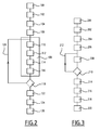
Figure 2 shows a flowchart of an example of the activation of the switching process in accordance with this invention when starting the electric machine inFigure 1 ; and -
Figure 3 shows a flowchart of an example of the activation of the switching process in accordance with this invention when stopping the electric machine inFigure 1 . - In the following text, the direction of the current is defined as being upstream-downstream.
- The
electrical system 10 inFigure 1 comprises asupply 12 of electrical voltage, adevice 14 for controlling theelectrical supply 12 and analternating current machine 16. Theelectrical supply 12 is connected to theelectrical machine 16 by aconnection 17. - The
electrical supply 12 comprises aninput 18 and anoutput 20. The input is connected to theelectrical network 22. Theelectrical network 22 is able to supply voltage and functions at a frequency known as the network frequency. In the case ofFigure 1 , the voltage supplied by theelectrical network 22 is a three-phase voltage. - The
electrical supply 12 contains two circuits, 24 and 26, connecting theinput 18 to theoutput 20. - The
first circuit 24 comprises just oneswitch 28. This switch will be referred to below as thenetwork switch 28. In fact, thenetwork switch 28 has an open position, in which theinput 18 and theoutput 20 are not connected via thefirst circuit 24, and a closed position, in which theinput 18 and theoutput 20 are in direct electrical contact. In this latter case, theoutput 20 is connected to theelectrical network 22. - The second circuit comprises, in series, a separating
transformer 30, an adjustable speed drive (ASD) 32, and aswitch 34. - The
transformer 30 is designed in such a manner that it brings about an effective separation between its primary circuit or circuits on one hand and its secondary circuit or circuits on the other. - The ASD 32 is capable of starting an alternating current
electric machine 16. - The
switch 34 of thesecond circuit 26 will be referred to below as theASD switch 34. In fact, theASD switch 34 has an open position in which theASD 32 and theoutput 20 of thepower supply 12 are not connected via thesecond circuit 26 and a closed position in which theASD 32 and theoutput 20 of thepower supply 12 are in direct electrical contact. - The
power supply 12 is thus able to operate according to three configurations. - In the first configuration, the
power supply 12 is able to deliver voltage through theelectrical network 22 on its own. In this case, thenetwork switch 28 is closed and theASD switch 34 is open. - In the second configuration, the
power supply 12 is able to deliver voltage through theASD 32 on its own. In this case, thenetwork switch 28 is open and theASD switch 34 is closed. - In the third configuration, the
power supply 12 is able to deliver voltage through theelectrical network 22 and theASD 32. In this case, the twoswitches - The
device 14 for controlling theelectrical supply 12 comprises aflux estimator 36 for theelectric machine 16, a speed measuring sensor orestimator 38 for theelectric machine 16, two sensors numbered 40 and 42 for measuring the voltage, and acontroller 44. - The
flux estimator 36 can estimate the flux by measuring the voltage and the current levels of theelectric machine 16 regardless of the nature of thepower supply 12 of the electric machine 16 (through theelectrical network 22 and/or through the ASD 32). - The
speed measuring sensor 38 of theelectric machine 16 is capable of measuring or estimating the speed of theelectric machine 16. - One
sensor 40 of the two voltage measuring sensors (40 and 42) is capable of measuring the voltage of theelectrical network 22 upstream of thenetwork switch 28. The othervoltage measuring sensor 42 is capable of measuring the voltage between theASD 32 and theASD switch 34. - The
flux estimator 36 and the three measuringsensors controller 44. - The
controller 44 is capable of controlling the voltage of theASD 32 and of opening and closing the twoswitches Figure 1 bydotted lines 48. - Moreover, the
controller 44 is capable of switching thepower supply 12 of anelectric machine 16 between a power supply by theASD 32 and theelectrical network 22. - The activation of the starting process of the
electric machine 16 is described by referring to the flowchart inFigure 2 . - In this case, it is a question of switching the
power supply 12 from a configuration where the voltage is supplied by theASD 32 on its own (ASD switch 34 closed and network switch 28 open) to a configuration where the voltage is supplied by the electrical network on its own (ASD switch 34 open and network switch 28 closed). - The process includes a
stage 100 for determining an ideal speed of rotation for anelectric machine 16. - By way of example, the ideal speed of rotation is chosen as being equal to the speed of rotation associated with the operating frequency of the
electrical network 22. - Alternatively, the ideal speed of rotation is chosen as being equal to the nominal speed of the
electric machine 16. - The process includes a
stage 102 for determining an ideal flux for theelectric machine 16. - By way of example, the ideal flux is chosen as being the nominal flux of the
electric machine 16. - When starting, the motor is initially stationary and the requirement is that the motor should be at the ideal speed of rotation while being supplied with voltage by the
electrical network 22. - The increase in the speed of rotation of the
electric machine 16 is ensured by astage 104, which sends an appropriate voltage command to theASD 32 through thecontroller 44. - The process thus includes a
stage 106 for measuring the speed of rotation of theelectric machine 16. - As soon as the measured speed of rotation exceeds a predetermined value for the ideal speed of rotation, a
stage 108 is activated to synchronise the phase and amplitude of the voltage delivered by theASD 32 with the voltage delivered by theelectrical network 22. - The predetermined value is less than 100% in order to ensure that the
synchronisation stage 108 commences before theelectric machine 16 achieves its ideal speed of rotation. Thesynchronisation stage 108 is activated if the speed of theelectric machine 16 continues to increase. - By way of example, the predetermined value is equal to about 90%, preferably about 95%, or even more preferably about 96%.
- The
synchronisation stage 108 includes astage 110 which measures, by thevoltage sensors ASD 32 and by theelectrical network 22. - The
synchronisation stage 108 includes astage 112 to calculate a signal representing the phase error between the voltages delivered by theASD 32 and theelectrical network 22. - By way of example, in the example in
Figure 2 , the signal representing the phase error is the phase difference between the voltage delivered by theASD 32 and the voltage of theelectrical network 22. - The
synchronisation stage 108 comprises astage 114 to calculate a signal representing the amplitude error between the voltage delivered by theASD 32 and theelectrical network 22. - By way of example, in the example in
Figure 2 , the signal representing the amplitude error is the difference in amplitude between the voltage delivered by theASD 32 and the voltage of theelectrical network 22. - The
synchronisation stage 108 thus includes astage 116 to generate a control signal for theASD 32 on the basis of two signals calculated from the ideal speed of rotation and from the ideal flux. - Within the framework of the example in
Figure 2 , the control signal is generated from two totals: one is the total of the ideal flux with the signal representing the amplitude in error, and the other is the total of the ideal speed of rotation with the signal representing the phase error. - For example, generation is set in motion by a method of "vector control" or "field-oriented control". The vector control method allows the speed and the flux of the
electric machine 16 to be controlled by controlling the voltage applied to theASD 32. - By way of illustration, a pulse width modulation (PWM) method can be used.
- The synchronisation stage is repeated in the event that two successive conditions are not satisfied. This is illustrated by the
test 118 in the flowchart inFigure 2 and by thearrow 120. - The two conditions are the synchronisation conditions with values bordering on the absolute value of the signals representing the phase and amplitude value.
- For example, the absolute value of the signal representing the phase error is compared to about 2 degrees. The absolute value of the signal representing the amplitude value is compared to about 2% of the voltage delivered by the
electrical network 22. - Once these two conditions are satisfied, the
synchronisation stage 108 is completed and the process includes astage 122, which sends a closing command to thenetwork switch 28 by thecontroller 44. -
Stage 122, which sends the closing command, generally takes place very soon after theelectric machine 16 has reached its ideal speed of rotation. Typically, it takes place in less than 3 seconds. When thenetwork switch 28 is closed as a result of the command sent by thecontroller 44 to the sendingstage 122, theelectric machine 16 is supplied simultaneously by theASD 32 and theelectrical network 22. - Moreover, the
ASD 32 phase is served by the phase of theelectrical network 22. For example, the locking is carried out by a locking phase or loop controlled by the phase (this is also referred to by the acronym PLL for "Phase-Locked Loop"). - The process thus includes a
stage 124 for controlling the voltage of theASD 32 to reduce the voltage and the current delivered by theASD 32. - If the current delivered by the
ASD 32 is below a predetermined threshold value, the process includes astage 126, in which a command is sent to thecontroller 44 to open theASD switch 34. - The predetermined threshold value is chosen in such a way that when the switch is opened, the
ASD 32 delivers a low-amplitude current. - For example, the predetermined threshold value corresponds to about 5% of the value of the current delivered by the
ASD 32 beforestage 124, which controls the voltage of theASD 32 in order to reduce the level of current delivered by theASD 32. - Alternatively, the predetermined threshold value can be equal to a fixed value. By way of illustration, this value is equal to about 5% of the nominal current. The activation of the process when the
electric machine 16 stops is described with reference to the flowchart inFigure 3 . - In this case, the
power supply 12 has to be switched from a configuration where the voltage is supplied by the electrical network on its own (ASD switch 34 open and network switch 28 closed) to a configuration where the voltage is supplied by theASD 32 on its own (ASD switch 34 closed and network switch 28 open). - The process includes a
stage 200 for measuring the speed of rotation of theelectric machine 16. - The process includes a
stage 202 for determining an ideal speed of rotation for theelectric machine 16. Thisstage 202 for determining an ideal speed of rotation is activated by choosing the measured speed of rotation as the ideal speed of rotation. - The process includes a
stage 204 for measuring the speed of rotation of theelectric machine 16 by theflux estimator 36. - The process includes a
stage 206 for determining an ideal flux for theelectric machine 16. Thisstage 206 for determining an ideal flux is activated by choosing the estimated flux as the ideal flux. - The process comprises a
synchronisation stage 208 identical to thesynchronisation stage 108 described above with reference toFigure 2 . In the same way, thesynchronisation stage 208 is repeated if the two successive synchronisation conditions similar to those in thetest 118 of the process described above are not satisfied. This is illustrated by thetest 210 and thearrow 212. - If the two conditions are satisfied, the
synchronisation stage 208 is completed and the process includes astage 214, in which a command is sent by thecontroller 44 to close theASD switch 34. - Once the
ASD switch 34 is closed as a result of the command sent by thecontroller 44, theelectric machine 16 is supplied simultaneously by theASD 32 and theelectrical network 22. - Moreover, the
ASD 32 phase is served by the phase of theelectrical network 22. For example, the locking is carried out by a locking phase or loop controlled by the phase (this is also referred to by the acronym PLL for "Phase-Locked Loop"). - The process thus includes a
stage 216 for controlling the voltage of theASD 32 to reduce the current delivered by theelectrical network 22 to theelectric machine 16. - If the current delivered by the
electrical network 22 to theelectric machine 16 is below a predetermined threshold value, the process includes astage 218, in which a command is sent by thecontroller 44 to open thenetwork switch 28. - The predetermined threshold value is chosen in such a way that when the
network switch 28 is opened, theelectrical network 22 delivers a low-amplitude current. - For example, the predetermined threshold value corresponds to about 5% of the value of the current delivered by the
electrical network 22 beforestage 126, which controls the voltage of theASD 32 in order to reduce the level of current delivered by theelectrical network 22 to theelectric machine 16. - Alternatively, the predetermined threshold can be a fixed value. By way of illustration, this value is equal to about 5% of the nominal current. The process thus includes a
stage 220 for stopping theelectric machine 16 by progressively reducing the level of voltage applied by theASD 32. This reduction is obtained by modifying the level of voltage by thecontroller 44. - In the two cases cited, the speed of the
electric machine 16 and the flux of theelectric machine 16 are used to generate a voltage command for theASD 32, which enables the frequency and the phase of the voltage delivered by theASD 32 to be synchronised with the voltage delivered by theelectrical network 22. The voltages generated by thecontroller 44 are characterised by an amplitude and an angle/frequency. The flux is directly linked to the amplitude of the voltages, while the speed directly influences the angle/frequency, which has an uncoupling effect between the actions of synchronisation: amplitude and angle of the voltage. - In each of the processes contained in
Figures 2 and 3 there is a moment, at which after synchronising the phase and the amplitude of the voltages, theelectrical network 22 and the ASD are simultaneously connected to theelectric machine 16 for the purpose of supplying the latter. - The process enables sudden changes in the level of current to the
electric machine 16 to be avoided during switching. Fluctuations in the voltage of theelectrical network 22 are also avoided. - The process enables a synchronisation of phase and amplitude to be obtained between the voltages delivered by the
ASD 32 and theelectrical network 22 more rapidly than in those processes that employ a synchronisation unit and a synchro-check relay. Synchronisation is obtained within a maximum of 3 seconds and typically takes between 1 and 2 seconds. This means that the duration of the synchronisation is improved by a factor of at least 10. - A faster synchronisation means that the use of ASDs operating at a lower dimensional power that the ASDs used in combination with a synchronisation unit and a synchro-check relay can be considered. Such ASDs have the particular advantage of being less costly to manufacture.
- In the case of the process that is used within the context of start-up, a faster synchronisation has the effect of reducing the heat produced by electronic components in the ASD during their operation. Benefiting from the thermal constancy of the
ASD 32 and using anASD 32, whose components do not need to be cooled with water, is now possible. - According to the proposed process, the value of the current passing through the
switches switches - The proposed process applies to all types of electric machines. The process is particularly applicable to induction motors, synchronous motors, and especially motors working with permanent magnets (also referred to as PMSM or "permanent magnet synchronous motors").
Claims (10)
- Process for switching the voltage supply (12) of an alternating current electric machine (16) between an adjustable speed drive (ASD) (32) and an electrical network (22), wherein the process includes a stage in which:- an ideal speed of rotation is determined for the electric machine (16); and- the phase and amplitude of the voltage delivered by the ASD (32) is synchronised with the voltage delivered by the electrical network (22);
wherein the synchronisation stage includes a stage in which:- the voltage delivered by the ASD (32) and the voltage delivered by the electrical network (22) are measured, and- the signals are calculated that represent, respectively, the difference in amplitude between the two measured voltages and the phase difference between the two measured voltages;wherein the process further includes a stage for determining an ideal flux for the electric machine (16); and
wherein the synchronisation stage further includes a stage for the generation of a command signal (e.g., a voltage command) for the voltage of the ASD (32) on the basis of the ideal flux, to which is added the signal representing the calculated difference in amplitude. - Process according to claim 1, in which the generation stage is activated while also taking into account the ideal speed of rotation, to which is added the signal representing the calculated phase difference.
- Process according to claim 1 or claim 2, in which the generation stage is activated by the use of a vector command method.
- Process according to claim 3, in which the vector command method used is the regulation of the amplitude of the flux and the speed.
- Process according to any preceding claim, in which the synchronisation stage is repeated if one or both of the following conditions are not satisfied:- the absolute value of the signal representing the phase difference is less than about 2 degrees and- the absolute value of the signal representing the amplitude difference is less than about 2% of the voltage delivered by the electrical network (22).
- Process according to preceding claim 5, in which the electrical network (22) is connected to the electric machine (16) by a first switch (28), and the ASD (32) is connected to the electric machine (16) by a second switch (34), and the electric machine (16) is initially only supplied by the electrical network (22);
and wherein the process further includes a stage for:- closing the second switch (34) if both conditions are satisfied;- sending a command to the ASD (32) to reduce the level of current supplied by the electrical network (22) to the electric machine (16);- opening the first switch (28). - Process according to claim 5, in which the electrical network (22) is connected to the electric machine (16) by a first switch (28), and the ASD (32) is connected to the electric machine (16) by a second switch (34), while the electric machine (16) is initially only supplied by the ASD (32);
and wherein the process further includes a stage for:- closing the first switch (28) if both conditions are satisfied;- sending a command to the ASD (32) to increase the level of current supplied by the electrical network (22) to the electric machine (16);- opening the second switch (34). - Process according to claim 7, in which the process also includes a stage for:- sending a command to the ASD (32) to increase the speed of rotation of the electric machine (16);- measuring the speed of rotation of the electric machine (16);and the synchronisation stage is activated once the speed of rotation of the electric machine (16) has reached a level equal to about 90% of the ideal speed of rotation.
- Process according to claim 8, in which the synchronisation stage is activated once the speed of rotation of the electric machine (16) has reached a level equal to about 96% of the ideal speed of rotation.
- Device (14) for controlling the voltage supply (12) to an alternating current electric machine (16), where the said electric machine (16) is capable of being powered by an ASD (32) and an electrical network (22), the device (14) comprising:- a sensor to measure the voltage (40) delivered by the ASD (32);- a sensor to measure the voltage (42) delivered by the electrical network (22); and- a controller (44) capable of activating the switching process according to any preceding claim.
Applications Claiming Priority (1)
| Application Number | Priority Date | Filing Date | Title |
|---|---|---|---|
| FR1262883A FR3000630B1 (en) | 2012-12-27 | 2012-12-27 | SWITCHING METHOD AND CONTROL DEVICE THEREFOR |
Publications (3)
| Publication Number | Publication Date |
|---|---|
| EP2750285A2 true EP2750285A2 (en) | 2014-07-02 |
| EP2750285A3 EP2750285A3 (en) | 2017-08-09 |
| EP2750285B1 EP2750285B1 (en) | 2020-03-25 |
Family
ID=48083280
Family Applications (1)
| Application Number | Title | Priority Date | Filing Date |
|---|---|---|---|
| EP13197676.3A Active EP2750285B1 (en) | 2012-12-27 | 2013-12-17 | Switching Process and Associated Control Device |
Country Status (6)
| Country | Link |
|---|---|
| US (1) | US9467075B2 (en) |
| EP (1) | EP2750285B1 (en) |
| CN (1) | CN103973185B (en) |
| BR (1) | BR102013033066A2 (en) |
| CA (1) | CA2836332A1 (en) |
| FR (1) | FR3000630B1 (en) |
Cited By (1)
| Publication number | Priority date | Publication date | Assignee | Title |
|---|---|---|---|---|
| EP3484009A1 (en) * | 2017-11-13 | 2019-05-15 | Hitachi, Ltd. | Hydropower generation system |
Families Citing this family (4)
| Publication number | Priority date | Publication date | Assignee | Title |
|---|---|---|---|---|
| CN109510471B (en) | 2017-09-15 | 2022-11-04 | 奥的斯电梯公司 | Frequency converter, bypass frequency conversion control system and switching control method thereof |
| EP3640073A1 (en) * | 2018-10-15 | 2020-04-22 | Sandvik Mining and Construction Oy | Mining vehicle, and method for starting an ac electric motor of a mining vehicle |
| FR3088504B1 (en) * | 2018-11-14 | 2023-06-30 | Ge Energy Power Conversion Technology Ltd | CONTROL METHOD FOR POWER CONVERTER, ASSOCIATED SYSTEM AND DEVICE |
| CN110932607A (en) * | 2019-12-20 | 2020-03-27 | 广西师范大学 | Distributed synchronous control method of multi-motor network system |
Family Cites Families (8)
| Publication number | Priority date | Publication date | Assignee | Title |
|---|---|---|---|---|
| US4587474A (en) * | 1984-07-02 | 1986-05-06 | General Electric Company | Control for bumpless transfer of an AC motor between a solid-state inverter and a supply mains |
| US4620296A (en) * | 1984-11-29 | 1986-10-28 | Dana Corporation | Protection system for immunizing a controlled d-c power supply against a-c line voltage interruptions |
| JPH0767313B2 (en) * | 1986-12-29 | 1995-07-19 | 富士電機株式会社 | Commercial switching control device |
| US5212438A (en) * | 1987-09-24 | 1993-05-18 | Kabushiki Kaisha Toshiba | Induction motor control system |
| JPH0654586A (en) * | 1992-07-28 | 1994-02-25 | Fuji Electric Co Ltd | Instantaneous power failure restart device for synchronous motor drive inverter |
| JP2001190091A (en) * | 1999-10-27 | 2001-07-10 | Fuji Electric Co Ltd | Operation switching device for induction motor |
| JP2005168092A (en) * | 2003-11-28 | 2005-06-23 | Toshiba Mitsubishi-Electric Industrial System Corp | Controller for ac motor |
| JP4116595B2 (en) * | 2004-06-30 | 2008-07-09 | ファナック株式会社 | Motor control device |
-
2012
- 2012-12-27 FR FR1262883A patent/FR3000630B1/en active Active
-
2013
- 2013-12-12 CA CA2836332A patent/CA2836332A1/en not_active Abandoned
- 2013-12-17 EP EP13197676.3A patent/EP2750285B1/en active Active
- 2013-12-20 BR BR102013033066A patent/BR102013033066A2/en not_active Application Discontinuation
- 2013-12-23 US US14/138,303 patent/US9467075B2/en active Active
- 2013-12-27 CN CN201310741496.3A patent/CN103973185B/en active Active
Non-Patent Citations (1)
| Title |
|---|
| "Generation electrique integree aux sites industriels et bdtiments commerciaux", SCHNEIDER ELECTRIC TECHNICAL BULLETIN, 2000 |
Cited By (1)
| Publication number | Priority date | Publication date | Assignee | Title |
|---|---|---|---|---|
| EP3484009A1 (en) * | 2017-11-13 | 2019-05-15 | Hitachi, Ltd. | Hydropower generation system |
Also Published As
| Publication number | Publication date |
|---|---|
| EP2750285B1 (en) | 2020-03-25 |
| CN103973185A (en) | 2014-08-06 |
| BR102013033066A2 (en) | 2016-01-05 |
| FR3000630A1 (en) | 2014-07-04 |
| US9467075B2 (en) | 2016-10-11 |
| CA2836332A1 (en) | 2014-06-27 |
| EP2750285A3 (en) | 2017-08-09 |
| US20140184132A1 (en) | 2014-07-03 |
| FR3000630B1 (en) | 2016-05-20 |
| CN103973185B (en) | 2018-09-18 |
Similar Documents
| Publication | Publication Date | Title |
|---|---|---|
| EP2787518B1 (en) | Two-step connection of electric motors by means of electromagnetic switches | |
| EP2750285B1 (en) | Switching Process and Associated Control Device | |
| CN105813882B (en) | Apparatus and method for operating an electric machine | |
| US10090790B2 (en) | Motor control device | |
| CN109314475A (en) | Method and apparatus for controlling threephase motor | |
| JP7412309B2 (en) | Grid integration device | |
| EP2779194A1 (en) | Two-step connection of electric motors by means of electromagnetic switches | |
| CN111052583B (en) | power conversion device | |
| KR101884545B1 (en) | Electric motor drive system | |
| CN106253778A (en) | The control device of synchronous motor | |
| EP2908427B1 (en) | Systems and methods for initializing a generator | |
| JP2017077079A (en) | Power converter | |
| EP1793486B1 (en) | Method for controlling ac motors | |
| CN107196579B (en) | A control method and control device for permanent magnet synchronous motor with speed re-input | |
| US12378969B2 (en) | Controller and drive circuit for electric motors | |
| CN113196646A (en) | Motor drive device, refrigeration circuit device, air conditioner, water heater, and refrigerator | |
| US11456683B2 (en) | Method for a network synchronization of a permanently excited three-phase machine comprising a soft starter which comprises thyristors | |
| JP2014165945A (en) | Drive device for compressor motor, and air conditioner | |
| CN110915122A (en) | Motor drive device and motor starting method | |
| CN213661495U (en) | A frequency converter synchronous switching circuit | |
| JP5478333B2 (en) | Motor control device and motor control method | |
| CN105813880B (en) | For making the apparatus and method of motor operation | |
| KR101632786B1 (en) | Inverter for Driving Induction Motor | |
| US20260128702A1 (en) | Controller and drive circuit for electric motors | |
| US20260128700A1 (en) | Controller and drive circuit for electric motors |
Legal Events
| Date | Code | Title | Description |
|---|---|---|---|
| 17P | Request for examination filed |
Effective date: 20131217 |
|
| AK | Designated contracting states |
Kind code of ref document: A2 Designated state(s): AL AT BE BG CH CY CZ DE DK EE ES FI FR GB GR HR HU IE IS IT LI LT LU LV MC MK MT NL NO PL PT RO RS SE SI SK SM TR |
|
| AX | Request for extension of the european patent |
Extension state: BA ME |
|
| PUAI | Public reference made under article 153(3) epc to a published international application that has entered the european phase |
Free format text: ORIGINAL CODE: 0009012 |
|
| PUAL | Search report despatched |
Free format text: ORIGINAL CODE: 0009013 |
|
| AK | Designated contracting states |
Kind code of ref document: A3 Designated state(s): AL AT BE BG CH CY CZ DE DK EE ES FI FR GB GR HR HU IE IS IT LI LT LU LV MC MK MT NL NO PL PT RO RS SE SI SK SM TR |
|
| AX | Request for extension of the european patent |
Extension state: BA ME |
|
| RIC1 | Information provided on ipc code assigned before grant |
Ipc: H02P 21/14 20160101AFI20170706BHEP Ipc: H02P 1/50 20060101ALI20170706BHEP Ipc: H02P 1/26 20060101ALI20170706BHEP Ipc: H02P 27/06 20060101ALI20170706BHEP Ipc: H02P 4/00 20060101ALI20170706BHEP |
|
| STAA | Information on the status of an ep patent application or granted ep patent |
Free format text: STATUS: REQUEST FOR EXAMINATION WAS MADE |
|
| R17P | Request for examination filed (corrected) |
Effective date: 20180122 |
|
| RBV | Designated contracting states (corrected) |
Designated state(s): AL AT BE BG CH CY CZ DE DK EE ES FI FR GB GR HR HU IE IS IT LI LT LU LV MC MK MT NL NO PL PT RO RS SE SI SK SM TR |
|
| GRAP | Despatch of communication of intention to grant a patent |
Free format text: ORIGINAL CODE: EPIDOSNIGR1 |
|
| STAA | Information on the status of an ep patent application or granted ep patent |
Free format text: STATUS: GRANT OF PATENT IS INTENDED |
|
| RIC1 | Information provided on ipc code assigned before grant |
Ipc: H02P 27/06 20060101ALI20190919BHEP Ipc: H02P 21/14 20160101AFI20190919BHEP Ipc: H02P 1/50 20060101ALI20190919BHEP Ipc: H02P 1/26 20060101ALI20190919BHEP Ipc: H02P 4/00 20060101ALI20190919BHEP Ipc: H02P 21/34 20160101ALI20190919BHEP |
|
| INTG | Intention to grant announced |
Effective date: 20191016 |
|
| GRAS | Grant fee paid |
Free format text: ORIGINAL CODE: EPIDOSNIGR3 |
|
| GRAA | (expected) grant |
Free format text: ORIGINAL CODE: 0009210 |
|
| STAA | Information on the status of an ep patent application or granted ep patent |
Free format text: STATUS: THE PATENT HAS BEEN GRANTED |
|
| AK | Designated contracting states |
Kind code of ref document: B1 Designated state(s): AL AT BE BG CH CY CZ DE DK EE ES FI FR GB GR HR HU IE IS IT LI LT LU LV MC MK MT NL NO PL PT RO RS SE SI SK SM TR |
|
| REG | Reference to a national code |
Ref country code: GB Ref legal event code: FG4D |
|
| REG | Reference to a national code |
Ref country code: AT Ref legal event code: REF Ref document number: 1249748 Country of ref document: AT Kind code of ref document: T Effective date: 20200415 Ref country code: IE Ref legal event code: FG4D |
|
| REG | Reference to a national code |
Ref country code: DE Ref legal event code: R096 Ref document number: 602013067121 Country of ref document: DE |
|
| PG25 | Lapsed in a contracting state [announced via postgrant information from national office to epo] |
Ref country code: FI Free format text: LAPSE BECAUSE OF FAILURE TO SUBMIT A TRANSLATION OF THE DESCRIPTION OR TO PAY THE FEE WITHIN THE PRESCRIBED TIME-LIMIT Effective date: 20200325 Ref country code: NO Free format text: LAPSE BECAUSE OF FAILURE TO SUBMIT A TRANSLATION OF THE DESCRIPTION OR TO PAY THE FEE WITHIN THE PRESCRIBED TIME-LIMIT Effective date: 20200625 Ref country code: RS Free format text: LAPSE BECAUSE OF FAILURE TO SUBMIT A TRANSLATION OF THE DESCRIPTION OR TO PAY THE FEE WITHIN THE PRESCRIBED TIME-LIMIT Effective date: 20200325 |
|
| PG25 | Lapsed in a contracting state [announced via postgrant information from national office to epo] |
Ref country code: BG Free format text: LAPSE BECAUSE OF FAILURE TO SUBMIT A TRANSLATION OF THE DESCRIPTION OR TO PAY THE FEE WITHIN THE PRESCRIBED TIME-LIMIT Effective date: 20200625 Ref country code: GR Free format text: LAPSE BECAUSE OF FAILURE TO SUBMIT A TRANSLATION OF THE DESCRIPTION OR TO PAY THE FEE WITHIN THE PRESCRIBED TIME-LIMIT Effective date: 20200626 Ref country code: HR Free format text: LAPSE BECAUSE OF FAILURE TO SUBMIT A TRANSLATION OF THE DESCRIPTION OR TO PAY THE FEE WITHIN THE PRESCRIBED TIME-LIMIT Effective date: 20200325 Ref country code: SE Free format text: LAPSE BECAUSE OF FAILURE TO SUBMIT A TRANSLATION OF THE DESCRIPTION OR TO PAY THE FEE WITHIN THE PRESCRIBED TIME-LIMIT Effective date: 20200325 Ref country code: LV Free format text: LAPSE BECAUSE OF FAILURE TO SUBMIT A TRANSLATION OF THE DESCRIPTION OR TO PAY THE FEE WITHIN THE PRESCRIBED TIME-LIMIT Effective date: 20200325 |
|
| REG | Reference to a national code |
Ref country code: NL Ref legal event code: MP Effective date: 20200325 |
|
| REG | Reference to a national code |
Ref country code: LT Ref legal event code: MG4D |
|
| PG25 | Lapsed in a contracting state [announced via postgrant information from national office to epo] |
Ref country code: NL Free format text: LAPSE BECAUSE OF FAILURE TO SUBMIT A TRANSLATION OF THE DESCRIPTION OR TO PAY THE FEE WITHIN THE PRESCRIBED TIME-LIMIT Effective date: 20200325 |
|
| PG25 | Lapsed in a contracting state [announced via postgrant information from national office to epo] |
Ref country code: IS Free format text: LAPSE BECAUSE OF FAILURE TO SUBMIT A TRANSLATION OF THE DESCRIPTION OR TO PAY THE FEE WITHIN THE PRESCRIBED TIME-LIMIT Effective date: 20200725 Ref country code: PT Free format text: LAPSE BECAUSE OF FAILURE TO SUBMIT A TRANSLATION OF THE DESCRIPTION OR TO PAY THE FEE WITHIN THE PRESCRIBED TIME-LIMIT Effective date: 20200818 Ref country code: CZ Free format text: LAPSE BECAUSE OF FAILURE TO SUBMIT A TRANSLATION OF THE DESCRIPTION OR TO PAY THE FEE WITHIN THE PRESCRIBED TIME-LIMIT Effective date: 20200325 Ref country code: LT Free format text: LAPSE BECAUSE OF FAILURE TO SUBMIT A TRANSLATION OF THE DESCRIPTION OR TO PAY THE FEE WITHIN THE PRESCRIBED TIME-LIMIT Effective date: 20200325 Ref country code: EE Free format text: LAPSE BECAUSE OF FAILURE TO SUBMIT A TRANSLATION OF THE DESCRIPTION OR TO PAY THE FEE WITHIN THE PRESCRIBED TIME-LIMIT Effective date: 20200325 Ref country code: SM Free format text: LAPSE BECAUSE OF FAILURE TO SUBMIT A TRANSLATION OF THE DESCRIPTION OR TO PAY THE FEE WITHIN THE PRESCRIBED TIME-LIMIT Effective date: 20200325 Ref country code: SK Free format text: LAPSE BECAUSE OF FAILURE TO SUBMIT A TRANSLATION OF THE DESCRIPTION OR TO PAY THE FEE WITHIN THE PRESCRIBED TIME-LIMIT Effective date: 20200325 Ref country code: RO Free format text: LAPSE BECAUSE OF FAILURE TO SUBMIT A TRANSLATION OF THE DESCRIPTION OR TO PAY THE FEE WITHIN THE PRESCRIBED TIME-LIMIT Effective date: 20200325 |
|
| REG | Reference to a national code |
Ref country code: AT Ref legal event code: MK05 Ref document number: 1249748 Country of ref document: AT Kind code of ref document: T Effective date: 20200325 |
|
| REG | Reference to a national code |
Ref country code: DE Ref legal event code: R097 Ref document number: 602013067121 Country of ref document: DE |
|
| PG25 | Lapsed in a contracting state [announced via postgrant information from national office to epo] |
Ref country code: DK Free format text: LAPSE BECAUSE OF FAILURE TO SUBMIT A TRANSLATION OF THE DESCRIPTION OR TO PAY THE FEE WITHIN THE PRESCRIBED TIME-LIMIT Effective date: 20200325 Ref country code: IT Free format text: LAPSE BECAUSE OF FAILURE TO SUBMIT A TRANSLATION OF THE DESCRIPTION OR TO PAY THE FEE WITHIN THE PRESCRIBED TIME-LIMIT Effective date: 20200325 Ref country code: ES Free format text: LAPSE BECAUSE OF FAILURE TO SUBMIT A TRANSLATION OF THE DESCRIPTION OR TO PAY THE FEE WITHIN THE PRESCRIBED TIME-LIMIT Effective date: 20200325 Ref country code: AT Free format text: LAPSE BECAUSE OF FAILURE TO SUBMIT A TRANSLATION OF THE DESCRIPTION OR TO PAY THE FEE WITHIN THE PRESCRIBED TIME-LIMIT Effective date: 20200325 |
|
| PLBE | No opposition filed within time limit |
Free format text: ORIGINAL CODE: 0009261 |
|
| STAA | Information on the status of an ep patent application or granted ep patent |
Free format text: STATUS: NO OPPOSITION FILED WITHIN TIME LIMIT |
|
| PG25 | Lapsed in a contracting state [announced via postgrant information from national office to epo] |
Ref country code: PL Free format text: LAPSE BECAUSE OF FAILURE TO SUBMIT A TRANSLATION OF THE DESCRIPTION OR TO PAY THE FEE WITHIN THE PRESCRIBED TIME-LIMIT Effective date: 20200325 |
|
| 26N | No opposition filed |
Effective date: 20210112 |
|
| PG25 | Lapsed in a contracting state [announced via postgrant information from national office to epo] |
Ref country code: SI Free format text: LAPSE BECAUSE OF FAILURE TO SUBMIT A TRANSLATION OF THE DESCRIPTION OR TO PAY THE FEE WITHIN THE PRESCRIBED TIME-LIMIT Effective date: 20200325 |
|
| REG | Reference to a national code |
Ref country code: CH Ref legal event code: PL |
|
| PG25 | Lapsed in a contracting state [announced via postgrant information from national office to epo] |
Ref country code: MC Free format text: LAPSE BECAUSE OF FAILURE TO SUBMIT A TRANSLATION OF THE DESCRIPTION OR TO PAY THE FEE WITHIN THE PRESCRIBED TIME-LIMIT Effective date: 20200325 |
|
| REG | Reference to a national code |
Ref country code: BE Ref legal event code: MM Effective date: 20201231 |
|
| PG25 | Lapsed in a contracting state [announced via postgrant information from national office to epo] |
Ref country code: IE Free format text: LAPSE BECAUSE OF NON-PAYMENT OF DUE FEES Effective date: 20201217 Ref country code: LU Free format text: LAPSE BECAUSE OF NON-PAYMENT OF DUE FEES Effective date: 20201217 |
|
| PG25 | Lapsed in a contracting state [announced via postgrant information from national office to epo] |
Ref country code: CH Free format text: LAPSE BECAUSE OF NON-PAYMENT OF DUE FEES Effective date: 20201231 Ref country code: LI Free format text: LAPSE BECAUSE OF NON-PAYMENT OF DUE FEES Effective date: 20201231 |
|
| PG25 | Lapsed in a contracting state [announced via postgrant information from national office to epo] |
Ref country code: TR Free format text: LAPSE BECAUSE OF FAILURE TO SUBMIT A TRANSLATION OF THE DESCRIPTION OR TO PAY THE FEE WITHIN THE PRESCRIBED TIME-LIMIT Effective date: 20200325 Ref country code: MT Free format text: LAPSE BECAUSE OF FAILURE TO SUBMIT A TRANSLATION OF THE DESCRIPTION OR TO PAY THE FEE WITHIN THE PRESCRIBED TIME-LIMIT Effective date: 20200325 Ref country code: CY Free format text: LAPSE BECAUSE OF FAILURE TO SUBMIT A TRANSLATION OF THE DESCRIPTION OR TO PAY THE FEE WITHIN THE PRESCRIBED TIME-LIMIT Effective date: 20200325 |
|
| PG25 | Lapsed in a contracting state [announced via postgrant information from national office to epo] |
Ref country code: MK Free format text: LAPSE BECAUSE OF FAILURE TO SUBMIT A TRANSLATION OF THE DESCRIPTION OR TO PAY THE FEE WITHIN THE PRESCRIBED TIME-LIMIT Effective date: 20200325 Ref country code: AL Free format text: LAPSE BECAUSE OF FAILURE TO SUBMIT A TRANSLATION OF THE DESCRIPTION OR TO PAY THE FEE WITHIN THE PRESCRIBED TIME-LIMIT Effective date: 20200325 |
|
| PG25 | Lapsed in a contracting state [announced via postgrant information from national office to epo] |
Ref country code: BE Free format text: LAPSE BECAUSE OF NON-PAYMENT OF DUE FEES Effective date: 20201231 |
|
| PGFP | Annual fee paid to national office [announced via postgrant information from national office to epo] |
Ref country code: DE Payment date: 20251126 Year of fee payment: 13 |
|
| PGFP | Annual fee paid to national office [announced via postgrant information from national office to epo] |
Ref country code: GB Payment date: 20251120 Year of fee payment: 13 |
|
| PGFP | Annual fee paid to national office [announced via postgrant information from national office to epo] |
Ref country code: FR Payment date: 20251120 Year of fee payment: 13 |