EP2750282A2 - Multi-axis motor driving system and motor driving apparatus - Google Patents
Multi-axis motor driving system and motor driving apparatus Download PDFInfo
- Publication number
- EP2750282A2 EP2750282A2 EP13197395.0A EP13197395A EP2750282A2 EP 2750282 A2 EP2750282 A2 EP 2750282A2 EP 13197395 A EP13197395 A EP 13197395A EP 2750282 A2 EP2750282 A2 EP 2750282A2
- Authority
- EP
- European Patent Office
- Prior art keywords
- regenerative
- power consumption
- motor driving
- voltage
- regenerative power
- Prior art date
- Legal status (The legal status is an assumption and is not a legal conclusion. Google has not performed a legal analysis and makes no representation as to the accuracy of the status listed.)
- Withdrawn
Links
Images





Classifications
-
- G—PHYSICS
- G05—CONTROLLING; REGULATING
- G05B—CONTROL OR REGULATING SYSTEMS IN GENERAL; FUNCTIONAL ELEMENTS OF SUCH SYSTEMS; MONITORING OR TESTING ARRANGEMENTS FOR SUCH SYSTEMS OR ELEMENTS
- G05B15/00—Systems controlled by a computer
- G05B15/02—Systems controlled by a computer electric
-
- H—ELECTRICITY
- H02—GENERATION; CONVERSION OR DISTRIBUTION OF ELECTRIC POWER
- H02P—CONTROL OR REGULATION OF ELECTRIC MOTORS, ELECTRIC GENERATORS OR DYNAMO-ELECTRIC CONVERTERS; CONTROLLING TRANSFORMERS, REACTORS OR CHOKE COILS
- H02P3/00—Arrangements for stopping or slowing electric motors, generators, or dynamo-electric converters
- H02P3/06—Arrangements for stopping or slowing electric motors, generators, or dynamo-electric converters for stopping or slowing an individual dynamo-electric motor or dynamo-electric converter
- H02P3/08—Arrangements for stopping or slowing electric motors, generators, or dynamo-electric converters for stopping or slowing an individual dynamo-electric motor or dynamo-electric converter for stopping or slowing a DC motor
- H02P3/14—Arrangements for stopping or slowing electric motors, generators, or dynamo-electric converters for stopping or slowing an individual dynamo-electric motor or dynamo-electric converter for stopping or slowing a DC motor by regenerative braking
-
- H—ELECTRICITY
- H02—GENERATION; CONVERSION OR DISTRIBUTION OF ELECTRIC POWER
- H02P—CONTROL OR REGULATION OF ELECTRIC MOTORS, ELECTRIC GENERATORS OR DYNAMO-ELECTRIC CONVERTERS; CONTROLLING TRANSFORMERS, REACTORS OR CHOKE COILS
- H02P5/00—Arrangements specially adapted for regulating or controlling the speed or torque of two or more electric motors
- H02P5/74—Arrangements specially adapted for regulating or controlling the speed or torque of two or more electric motors controlling two or more AC dynamo-electric motors
Definitions
- the embodiment disclosed herein relates to a multi-axis motor driving system and a motor driving apparatus.
- Japanese Patent No. 3547594 discloses a configuration in which a system controller or a master motor control device is provided for a plurality of motor control devices that share a PN voltage of the common DC power source so as to avoid concentration of regenerative power on a regenerative resistor of any of the motor control devices.
- the system controller or the master motor control device is configured to adjust regenerative operation voltage levels of the motor control devices so that respective regenerative circuits may operate evenly to minimize a gap of a regenerative load consumption amount among the motor control devices.
- the system controller or the master motor control device needs to perform control dedicated for regenerative processing, such as receiving regenerative load data calculated by each motor control device and comparing the regenerative load data to adjust the regenerative operation voltage levels of the motor control devices.
- the system controller needs to be provided as a purpose-built device independent from the plurality of motor control devices.
- the master motor control device is configured to have a specially high processing ability in order to have one of the plurality of motor control devices manage the other motor control devices. If such an independent system controller or such a special master motor control device is provided, the overall motor control system becomes complicated as a result.
- An embodiment shown hereinafter has been made in view of the above-mentioned problem, and it is an object thereof to provide a multi-axis motor driving system and a motor driving apparatus that are configured to avoid a regenerative overload on each regenerative resistor with a simple configuration without additionally providing a system controller or a master motor driving apparatus for centrally controlling regenerative operation of a plurality of motor driving apparatuses.
- a multi-axis motor driving system includes a plurality of drivers respectively connected to a plurality of motors, the plurality of drivers being connected to the common DC bus, the plurality of drivers each including: a regenerative power consumption unit for consuming regenerative power generated from a corresponding one of the plurality of motors; and a regenerative controller for controlling start and stop of activation of the regenerative power consumption unit based on a voltage of the common DC bus.
- a motor driving apparatus includes: an output line to be connected to a motor; an input line to be connected to the common DC bus shared by another motor driving apparatus; a regenerative power consumption unit for consuming regenerative power generated from the motor; and a regenerative controller for controlling start and stop of activation of the regenerative power consumption unit based on the voltage of the common DC bus.
- a multi-axis motor driving system S includes one converter 2 connected to a three-phase AC power source 1, a plurality of motor driving apparatuses 3, and motors 4 respectively connected to the motor driving apparatuses 3.
- the converter 2 rectifies and smoothes AC power supplied from the three-phase AC power source 1 to convert the AC power into DC power, and outputs the DC power to a DC bus 5 including a pair of two lines, i.e., a P line on the positive side and an N line on the negative side.
- the plurality of motor driving apparatuses 3 are connected to the common DC bus 5 to be supplied with the DC power, and respectively control the drive of the motors 4 connected thereto, based on a control command input from an unillustrated host control device.
- each motor 4 is a rotary three-phase AC motor
- each motor driving apparatus 3 converts the DC power supplied from the converter 2 through the DC bus 5 into three-phase AC power whose amplitude and frequency are arbitrarily modulated, and controls the torque, the rotation speed, and the rotation position of each motor 4 connected thereto. Then, the motors 4 are driven by the host control device in an integrated manner, thereby controlling the drive of a multi-axis machine as exemplified by so-called factory automation (not drawn) as a whole.
- the motor 4 includes a position detector such as an unillustrated encoder for detecting its own rotation position.
- the multi-axis motor driving system S is described by way of a four-axis configuration including four pairs of the motor driving apparatuses 3 and the motors 4, and the motor driving apparatuses 3 are configured to mutually transmit and receive information via a network 6.
- the motor driving apparatus 3 corresponds to the above-mentioned driver.
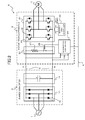
- FIG. 2 illustrates a circuit configuration of a combination of the converter 2 and one motor driving apparatus 3.
- Any of the motor driving apparatuses 3 has basically the same circuit configuration, although varying in capacity, parameter, and the like.
- the converter 2 includes a rectifier 11 and a smoothing capacitor 12.
- the rectifier 11 is a diode bridge including six diodes 13.
- the rectifier 11 performs full-wave rectification on AC power supplied from the three-phase AC power source 1 and outputs the resultant DC power to the DC bus 5.
- the smoothing capacitor 12 is connected across the DC bus 5 to smooth the DC power obtained by the full-wave rectification of the rectifier 11.
- the motor driving apparatus 3 includes an inverter unit 21, an inverter drive controller 22, a regenerative power consumption unit 23, and a regenerative controller 24.
- the inverter unit 21 is a device in which six arm switching elements 25 made of semiconductor such as IGBTs and six diodes 26 are bridge-connected. Specifically, two circuits in each of which the arm switching element 25 and the diode 26 as a flywheel diode (FWD) are connected in parallel are connected in series as a pair, and three pairs of the series circuits are connected in parallel to the smoothing capacitor 12.
- each arm switching element 25 Upon receiving a gate signal from the inverter drive controller 22, each arm switching element 25 performs switching so that the DC power on the smoothing capacitor 12 side may be output from an intermediate connection position of each pair correspondingly to the respective phases of the three-phase AC motor 4.
- the motor 4 when the motor 4 suddenly decelerates or suddenly stops, the motor 4 functions as a generator to generate regenerative power that is back-fed to the DC bus 5 from the motor 4.
- rotational (kinetic) energy is converted into regenerative power (regenerative energy)
- regenerative power flows from the motor 4 into the DC circuit in the converter 2 through the DC bus 5 via the diodes 26 of the inverter unit 21.
- This operation of generating the regenerative power in the inverter unit 21 is hereinafter referred to as "regenerative operation”.
- the inverter drive controller 22 is configured by software executed by an unillustrated CPU.
- the inverter drive controller 22 controls the inverter unit 21 by outputting a gate signal based on PWM control to each of the arm switching elements 25 of the inverter unit 21 so that desired power may be supplied to the motor 4 based on a motor control command from the host control device (not shown).
- the regenerative power consumption unit 23 is, for example, a series circuit of a regenerative resistor 27 and an activation switch 28.
- the regenerative power consumption unit 23 is connected across the DC bus 5 in the motor driving apparatus 3.
- the activation switch 28 When the activation switch 28 is connected (turned ON), the regenerative power that is back-fed to the DC bus 5 by the above-mentioned regenerative operation is allowed to flow through the regenerative resistor 27 to be consumed.
- the activation switch 28 may be composed of a mechanical switch such as a relay or an electrical switch such as a high breakdown voltage transistor.
- the regenerative controller 24 is configured by software executed by the unillustrated CPU.
- the regenerative controller 24 appropriately controls the start and stop of activation of the regenerative power consumption unit 23 (turns ON and OFF the activation switch 28) so that the smoothing capacitor 12 may not be overcharged or the DC bus voltage may not be boosted excessively due to an increase in the back-fed regenerative power.
- the respective regenerative power consumption units 23 are also connected in parallel to each other, and the activation thereof is individually controlled by the corresponding regenerative controller 24.
- the regenerative controllers 24 of the motor driving apparatuses 3 each detect a DC voltage Vdc of the DC bus 5, and also mutually transmit and receive other information related to the regenerative control via the network 6.
- each regenerative controller 24 starts the activation of the regenerative power consumption unit 23 at the time at which the DC voltage Vdc detected from the DC bus 5 exceeds a predetermined threshold (before the smoothing capacitor 12 is overcharged) in order to suppress the damage to the smoothing capacitor 12 due to an overcharge.
- a predetermined threshold before the smoothing capacitor 12 is overcharged
- an error fluctuation
- Vdc detected from the common DC bus 5 among the plurality of motor driving apparatuses 3 because of hardware precision limitations such as a difference in balance at the component level.
- the regenerative power is consumed in a concentrated manner by one (or a small number of) regenerative power consumption unit 23 that has started to activate first. Then, the charge of the smoothing capacitor 12 in the converter 2 is stopped, and the increase in the voltage Vdc of the DC bus 5 stops. Thus, in the other motor driving apparatuses 3, the detected DC bus voltage Vdc does not exceed the threshold and the regenerative power consumption unit 23 does not start to activate. As a result, a regenerative load (regenerative power) is concentrated only on the regenerative power consumption unit 23 that has already started to activate.
- the regenerative resistor 27 of this regenerative power consumption unit 23 may become a regenerative overload condition and is damaged.
- the regenerative controller 24 of each motor driving apparatus 3 controls the start and stop of activation based on the voltage Vdc of the common DC bus 5 so that an excessive regenerative load may not be concentrated on each regenerative power consumption unit 23.
- all the regenerative power consumption units 23 are started to activate at substantially the same time through mutual monitoring among the motor driving apparatuses 3 via the network 6, and the regenerative power is dispersed to the regenerative controllers 24 of the motor driving apparatuses 3 and consumed.
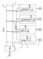
- FIG. 3 illustrating a simplified circuit configuration of the multi-axis motor driving system S
- a description is now given of the contents of control of the regenerative controller 24 according to an example of this embodiment.
- the inside of the regenerative controller 24 is illustrated by software blocks corresponding to the control procedures.
- the regenerative controllers 24 detect the same DC bus voltage Vdc0, and mutually transmit and receive detection voltages Vdc0, Vdc1, Vdc2, and Vdc3 via the network 6 to monitor each other.
- the regenerative controller 24 corrects its own detection voltage Vdc0 itself (or adjusts a detection gain to correct the detection voltage Vdc0) based on a comparison of the detection voltages Vdc0 to Vdc3, thereby being capable of minimizing an error of detection voltages Vdc0' to Vdc3' among the regenerative controllers 24. Note that, it is the corrected detection voltages Vdc0' to Vdc3' that are transmitted and received via the network 6.
- the regenerative power consumption units 23 of the motor driving apparatuses 3 can be started to activate at substantially the same time.
- the above-mentioned threshold Vref corresponds to a predetermined threshold.
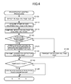
- Processing illustrated in the flow of FIG. 4 is invoked at a predetermined cycle and repeatedly executed. Note that, when each motor driving apparatus 3 is powered on, the activation switch 28 of any of the regenerative power consumption units 23 needs to be turned OFF.
- Step S105 the regenerative controller 24 detects the DC bus voltage Vdc0. In a hardware manner, a voltage of a DC power supply line connected to the DC bus in the motor driving apparatus 3 is detected.
- the regenerative controller 24 acquires DC bus voltages Vdc1', Vdc2', and Vdc3' via the network 6, which are detected (and corrected) and transmitted by the regenerative controller 24 of other motor driving apparatuses 3.
- Step S115 The regenerative controller 24 compares its own DC bus voltage Vdc0 detected in Step S105 (hereinafter referred to as “detection voltage”) to the other DC bus voltages Vdc1' to Vdc3' acquired in Step S110 (hereinafter referred to as “acquired voltages").
- Step S120 The regenerative controller 24 determines whether or not the detection voltage Vdc0 is greatly different from the other acquired voltages Vdc1' to Vdc3'. In other words, the regenerative controller 24 determines whether or not the motor driving apparatus 3 to which it belongs has solely detected a greatly different voltage value for the same DC bus voltage. When the detection voltage Vdc0 is greatly different, the determination criterion is satisfied, and the flow proceeds to Step S125.
- Step S125 based on the difference between the detection voltage Vdc0 and the acquired voltages Vdc1' to
- the regenerative controller 24 corrects the detection voltage Vdc0 itself or appropriately adjusts the detection gain of the regenerative controller 24 for the DC bus voltage.
- Step S130 The regenerative controller 24 transmits a corrected detection voltage Vdc0' to the other motor driving apparatuses 3 via the network 6. Then, the flow proceeds to next Step S140.
- Step S120 when it is determined in Step S120 that the detection voltage Vdc0 is not greatly different from the other acquired voltages Vdc1' to Vdc3', the determination criterion is not satisfied, and the flow proceeds to Step S135.
- Step S135 the regenerative controller 24 transmits the detection voltage Vdc0 as it is to the other motor driving apparatuses 3 via the network 6. Then, the flow proceeds to next Step S140.
- Step S140 the regenerative controller 24 determines whether or not the detection voltage Vdc0 or the corrected detection voltage Vdc0' is higher than a predetermined threshold Vref.
- the threshold Vref is set to be, for example, slightly lower than a voltage value at which the smoothing capacitor 12 of the converter 2 is overcharged.
- Step S145 when the detection voltage Vdc0 (Vdc0') exceeds the threshold Vref, the determination criterion is satisfied, and the flow proceeds to Step S145.
- Step S145 the regenerative controller 24 turns ON the activation switch 28 of the regenerative power consumption unit 23 of this motor driving apparatus 3. Then, this flow is finished.
- Step S105 functions as a voltage detector
- the procedure of Step S140 and Step S145 functions as a first normal starter
- the procedure of Step S125 functions as a detection corrector
- each motor driving apparatus 3 includes the regenerative controller 24 for controlling the start and stop of activation of the regenerative power consumption unit 23 based on the voltage Vdc of the DC bus 5 so that an excessive regenerative load may not be concentrated on each regenerative power consumption unit 23. Consequently, the damage to each regenerative power consumption unit 23 due to a regenerative overload can be suppressed with the use of a simple configuration without additionally providing a host device or a master servo (special driving device) for centrally managing the activation of each regenerative power consumption unit 23.
- the regenerative controllers 24 included in the respective motor driving apparatuses 3 start the activation of all the regenerative power consumption units 23 at substantially the same time.
- the regenerative load is not concentrated on one or a small number of regenerative power consumption units 23, and the regenerative power can be dispersed to all the regenerative power consumption units 23 and consumed. Consequently, the damage to the regenerative power consumption unit 23 due to a regenerative overload can be suppressed.
- the regenerative controllers 24 of the motor driving apparatuses 3 individually detect the same DC bus voltage Vdc0 by the procedure of Step S105, and start to activate the corresponding regenerative power consumption unit 23 of the motor driving apparatus 3 based on the comparison between the detection voltage Vdc0 and the predetermined threshold Vref set in common among the motor driving apparatuses 3 by the procedure of Step S140 and Step S145.
- the regenerative controllers 24 of the motor driving apparatuses 3 mutually monitor the detection voltages Vdc0 to Vdc3 to correct their own detection voltage Vdc0 (or adjust the detection gain or the like) by the procedure of Step S125, thereby being capable of minimizing an error of the detection voltages Vdc0 to Vdc3 among the motor driving apparatuses 3.
- all the regenerative power consumption units 23 can be activated at substantially the same time so that the regenerative power may be dispersed to the regenerative power consumption units 23 and consumed. Consequently, the damage to each regenerative power consumption unit 23 due to a regenerative overload can be suppressed.
- the regenerative controllers 24 of the motor driving apparatuses 3 mutually monitor the corrected detection voltages Vdc0' to Vdc3', and correct their own detection voltage Vdc0 based on the comparison of the corrected detection voltages Vdc0' to Vdc3', thereby minimizing an error of the detection voltages Vdc0 to Vdc3 with respect to the voltage Vdc of the common DC bus 5 among the regenerative controllers 24. Then, based on the comparison to the threshold Vref that is set to the same value by each regenerative controller 24 in a software manner, the regenerative power consumption units 23 of the motor driving apparatuses 3 are started to activate at substantially the same time.
- the regenerative controllers 24 may properly correct the respective thresholds Vref so that the regenerative power consumption units 23 of the motor driving apparatuses 3 may be started to activate at substantially the same time.
- the regenerative controllers 24 mutually transmit and receive the detection voltages Vdc0 to Vdc3 without any correction via the network 6.
- each of the regenerative controllers 24 only needs to appropriately correct an individually set threshold Vref0 so that the regenerative power consumption units 23 may be started to activate at substantially the same time, based on the comparison of the detection voltages Vdc0 to Vdc3 on the assumption that the detection voltages Vdc0 to Vdc3 are obtained from the same DC bus voltage Vdc.
- the regenerative controllers 24 may also mutually transmit and receive the respective individually set thresholds Vref0 to Vref3, and may correct the thresholds Vref0 to Vref3 based on the relationships between the detection voltages Vdc0 to Vdc3 and the thresholds Vref0 to Vref3.
- the plurality of motor driving apparatuses 3 share the single converter 2 as their power supply units, but this embodiment is not limited thereto.
- the plurality of motor driving apparatuses 3 only need to be connected with each other via the common DC bus, and each motor driving apparatus 3 may independently include a power supply unit such as a converter or may additionally be connected to an external power source such as a battery, for example.
- the regenerative controllers 24 of the plurality of motor driving apparatuses 3 are configured to mutually monitor the voltage values Vdc0' to Vdc3' detected from the common DC bus 5 and correct their own detection voltage Vdc0 so as to minimize an error among the voltage values Vdc0' to Vdc3'. In this manner, all the regenerative power consumption units 23 are started to activate at substantially the same time.
- each motor driving apparatus 3 may be configured to determine the start of activation of the regenerative power consumption units 23 in the other motor driving apparatuses 3 and start the activation of its own regenerative power consumption unit 23 when determining that at least one of the regenerative power consumption units has started to activate.
- each regenerative controller 24A performs two start determinations in parallel. In the first start determination, the regenerative controller 24A simply compares the detection voltage Vdc0 obtained from the DC bus 5 and the common threshold Vref to each other, and starts the activation of the regenerative power consumption unit 23 when the detection voltage Vdc0 exceeds the threshold Vref.
- the regenerative controller 24A determines the start of activation of the regenerative power consumption units 23 included in the other motor driving apparatuses 3A based on motor speeds FB1, FB2, and FB3 of the other motor driving apparatuses 3A acquired via the network 6 and the above-mentioned detection voltage Vdc0.
- the regenerative controller 24A determines the start of activation of at least one of the regenerative power consumption units 23, the regenerative controller 24A also starts the activation of its own regenerative power consumption unit 23.
- a multi-axis motor driving system SA includes a speed detector 7 for detecting a speed FB0 of a motor connected to the motor driving apparatus 3A, and transmits the detected speed FB0 as it is to the other motor driving apparatuses 3A via the network 6.
- a motor speed obtained within the motor driving apparatus 3A through differential operation of rotation position detection signals of the position detector included in the motor 4 may be used.
- a speed command generated inside each motor driving apparatus 3A or a speed command supplied from the unillustrated host device may be used.
- the regenerative controller 24A determines based on a temporal change of the detected speed FB1 of any of the other motor driving apparatuses 3A that the motor 4 connected to this motor driving apparatus 3A is decelerating or is suddenly stopped, it is determined that the motor 4 at this time is in a regenerative operation state in which the motor 4 generates regenerative power. Further, when the detection voltage Vdc0 is lower than a normal voltage (for example, a minimum voltage that can be maintained at the DC bus 5 while all the motor driving apparatuses 3A are being activated without the regenerative operation), it is determined that the regenerative power consumption unit 23 of the above-mentioned motor driving apparatus 3A has started to activate at this time to decrease the voltage of the DC bus 5.
- a normal voltage for example, a minimum voltage that can be maintained at the DC bus 5 while all the motor driving apparatuses 3A are being activated without the regenerative operation
- the regenerative controller 24A determines that the activation of the regenerative power consumption unit 23 in at least one of the other motor driving apparatuses 3A has started, the regenerative controller 24A also starts the activation of the regenerative power consumption unit 23 of the motor driving apparatus 3A to which it belongs.
- the regenerative controller 24A of each motor driving apparatus 3A performs the first and second start determinations in parallel, and hence all the regenerative power consumption units 23 can start to activate at substantially the same time.
- processing illustrated in the flow of FIG. 6 is also invoked at a predetermined cycle and repeatedly executed.
- the activation switch 28 of any of the regenerative power consumption units 23 needs to be turned OFF.
- Step S205 the regenerative controller 24A detects the motor speed FB0.
- the motor speed FB0 is detected from the speed detector 7 such as a tachogenerator provided in the motor 4 connected to the motor driving apparatus 3A.
- Step S210 The regenerative controller 24A transmits the motor speed FB0 detected in Step S205 to the other motor driving apparatuses 3A via the network 6.
- the regenerative controller 24A detects the DC bus voltage Vdc0 (similarly to Step S105 in the above-mentioned configuration).
- Step S220 The regenerative controller 24A determines whether or not the detection voltage Vdc0 detected in Step S215 is higher than a predetermined threshold Vref (the threshold Vref is equivalent to that in Step S140 in the above-mentioned configuration). When the detection voltage Vdc0 is larger than the threshold Vref, the determination criterion is satisfied, and the flow proceeds to Step S225.
- a predetermined threshold Vref the threshold Vref is equivalent to that in Step S140 in the above-mentioned configuration.
- Step S225 the regenerative controller 24A turns ON the activation switch 28 of the regenerative power consumption unit 23 of this motor driving apparatus 3A. Then, this flow is finished.
- Step S220 when it is determined in Step S220 that the detection voltage Vdc0 is equal to or smaller than the threshold Vref, the determination criterion is not satisfied, and the flow proceeds to Step S230.
- Step S230 the regenerative controller 24A acquires the motor speeds FB1, FB2, and FB3, which are detected and transmitted by the regenerative controllers 24A of the other motor driving apparatuses 3A via the network 6.
- Step S235 Based on temporal changes of the other motor speeds FB1 to FB3 acquired in Step S230, the regenerative controller 24A determines whether or not at least one of the motors 4 is decelerating or is suddenly stopped. In other words, the regenerative controller 24A determines whether or not at least one of the plurality of motor driving apparatuses 3A is in the regenerative operation state. When it is determined that none of the motor speeds FB1 to FB3 indicates the decelerating state or the suddenly stopped state, the determination criterion is not satisfied, and this flow is finished without any further processing.
- Step S240 When at least one of the motor speeds FB1 to FB3 indicates the decelerating state or the suddenly stopped state, on the other hand, the determination criterion is satisfied, and the flow proceeds to Step S240.
- Step S240 the regenerative controller 24A determines whether or not the DC bus voltage Vdc0 detected in Step S215 is lower than a predetermined threshold Vlow.
- the threshold Vlow is set to be, for example, a DC bus voltage value low enough so that it is not obtained unless any of the regenerative power consumption units 23 starts to activate to consume regenerative power.
- the detection voltage Vdc0 is equal to or higher than the threshold Vlow, the determination criterion is not satisfied, and the flow is finished without any further processing. In this case, it is determined that regenerative power is charging the smoothing capacitor 12.
- Step S225 it is determined that the regenerative power consumption unit 23 of any of the other motor driving apparatuses 3A has started to activate. Then, the regenerative controller 24A turns ON the activation switch 28 of the regenerative power consumption unit 23 of this motor driving apparatus 3A, and this flow is finished.
- Step S215 functions as a voltage detector
- the procedure of Step S220 and Step S225 functions as a first normal starter
- the procedure of Step S205 functions as a speed detector
- the procedure of Step S235, Step S240, and Step S225 functions as a first determination starter.
- all the regenerative power consumption units 23 can be started to activate at substantially the same time, similarly to the above-mentioned configuration. Consequently, the regenerative power can be distributed to all the regenerative power consumption units 23 and be consumed, and hence the damage to each regenerative power consumption unit 23 due to a regenerative overload can be suppressed.
- all the regenerative power consumption units 23 are started to activate at substantially the same time, to thereby suppress the damage to each regenerative power consumption unit 23 due to a regenerative overload.
- This embodiment is not limited thereto.
- the regenerative power consumption units 23 may be started to activate in descending order of their regenerative capacities.
- the magnitude of the resistance value of the regenerative resistor 27 is hereinafter taken as a specific example of the regenerative capacity, but instead, an ability to consume a certain regenerative power may be used as the regenerative capacity.
- the regenerative power consumption unit 23 When the regenerative capacity of the regenerative power consumption unit 23 is sufficiently large, even if the magnitude of a regenerative load becomes closer to the rated value of its regenerative capacity, the regenerative resistor 27 is not damaged unless the smoothing capacitor 12 of the converter 2 is gradually re-charged to increase the DC bus voltage Vdc to a certain degree. In other words, the regenerative power consumption unit 23 having a larger regenerative capacity has a higher durability against an abrupt change of the regenerative load.
- the regenerative power consumption unit 23 having a larger regenerative capacity is used correspondingly in the motor driving apparatus 3B.
- the motor driving apparatuses 3B having different drive capacities and the regenerative power consumption units 23 having different regenerative capacities are mixed in the multi-axis motor driving system SB, if the regenerative power consumption unit 23 having a small regenerative capacity starts to activate first, the regenerative load concentrated on this regenerative power consumption unit 23 immediately exceeds its regenerative capacity to damage the regenerative power consumption unit 23.
- the regenerative power consumption units 23 may be started to activate in descending order of regenerative capacities (in descending order of resistance values of the regenerative resistors 27), the regenerative capacities of the regenerative power consumption units 23 to be activated can be appropriately increased as a whole in accordance with the increase in regenerative load. Also with this method, the damage to a specific regenerative power consumption unit 23 due to a regenerative overload can be suppressed.
- the regenerative controllers 24B individually detect the same DC bus voltage, and each start the activation of the regenerative power consumption unit 23 of the motor driving apparatus 3B based on a comparison between the detection voltage Vdc0 and an individually set threshold Vval0.
- the individually set threshold Vval0 is a threshold that is stored individually by each regenerative controller 24B in a changeable manner, and is basically set to the same value by default at the time of factory shipment.
- the regenerative controller 24B outputs a warning signal via the network 6, and the motor driving apparatuses 3B mutually monitor the warning signal.
- the concentrated regenerative load immediately comes up close to its regenerative capacity, and the regenerative controller 24B of this motor driving apparatus 3B outputs a warning signal.
- the regenerative controller 24B of each motor driving apparatus 3B starts the activation of its own regenerative power consumption unit 23 when detecting that at least one of the other motor driving apparatuses 3B has output a warning signal. In this manner, all the regenerative power consumption units 23 can be started to activate.
- the motor driving apparatus 3B that has output a warning signal stops the activation of the regenerative power consumption unit 23, and adds a predetermined correction value ⁇ Vval (>0) to the individually set threshold Vval0 to correct the threshold Vva10.
- the activation start time can be delayed more for the regenerative power consumption unit 23 having a smaller regenerative capacity.
- the respective activation start times can be optimized so that the regenerative power consumption units 23 may be started to activate in descending order of their regenerative capacities.
- the concentrated regenerative load immediately exceeds its regenerative capacity to damage the regenerative power consumption unit 23 as described above.
- the regenerative power consumption unit 23 having a large regenerative capacity starts to activate first, on the other hand, it takes a relatively long time for the regenerative load to become closer to its regenerative capacity. Further, even if the regenerative load becomes closer to the regenerative capacity, as described above, the DC bus voltage Vdc can be increased again to a certain degree in the meantime, and the next regenerative power consumption unit 23 can be started to activate.
- the regenerative capacities of the regenerative power consumption units 23 to be activated can be appropriately increased as a whole in accordance with the increase in regenerative load. Consequently, the damage to the regenerative power consumption unit 23 due to a regenerative overload can be suppressed.
- processing illustrated in the flow of FIG. 8 is also invoked at a predetermined cycle and repeatedly executed.
- the individually set thresholds Vval0 of all the regenerative controllers 24B need to be set to the same value by default at the time of factory shipment of the motor driving apparatuses 3B.
- Step S305 the regenerative controller 24B determines whether or not the activation switch 28 of the regenerative power consumption unit 23 has already been in the ON state.
- the determination criterion is satisfied, and the flow proceeds to Step S335.
- Step S310 When the activation switch 28 is in the OFF state at this time, on the other hand, the determination criterion is not satisfied, and the flow proceeds to Step S310.
- Step S310 the regenerative controller 24B detects the DC bus voltage Vdc0 (similarly to Step S105 and Step S215 in the firstly-mentioned configuration and the first modified example, respectively).
- Step S315. The regenerative controller 24B determines whether or not the detection voltage Vdc0 detected in Step S310 is higher than an individually set threshold Vva10. When the detection voltage Vdc0 is equal to or lower than the individually set threshold Vval0, the determination criterion is not satisfied, and the flow proceeds to Step S320.
- Step S320 the regenerative controller 24B confirms whether or not a warning signal is transmitted from another motor driving apparatus 3B via the network 6.
- Step S325. The regenerative controller 24B determines whether or not it is confirmed in Step S320 that the warning signal has been transmitted from at least one of the motor driving apparatuses 3B. When it is confirmed that no warning signal has been transmitted, the determination criterion is not satisfied, and this flow is finished without any further processing.
- Step S330 When it is confirmed that the warning signal has been transmitted from at least one of the motor driving apparatuses 3B, on the other hand, the determination criterion is satisfied, and the flow proceeds to Step S330.
- Step S315 When it is determined in Step S315 that the detection voltage Vdc0 is higher than the individually set threshold Vval0, on the other hand, the determination criterion is satisfied, and the flow proceeds to Step S330.
- Step S330 the regenerative controller 24B turns ON the activation switch 28 of the regenerative power consumption unit 23 of this motor driving apparatus 3B.
- the regenerative controller 24B measures a time during which the detection voltage Vdc0 detected in Step S310 is higher than the individually set threshold Vval0, regards this state as a regenerative load, and determines whether or not the regenerative load is sufficiently smaller than the regenerative capacity of the regenerative power consumption unit 23. In other words, the regenerative controller 24B determines whether or not the regenerative load come up close to the regenerative capacity.
- the detection voltage Vdc0 is sufficiently smaller than the regenerative capacity of the regenerative power consumption unit 23, the determination criterion is satisfied, and this flow is finished without any further processing.
- Step S340 When the detection voltage Vdc0 come up close to the regenerative capacity of the regenerative power consumption unit 23, on the other hand, the determination criterion is not satisfied, and the flow proceeds to Step S340.
- Step S340 the regenerative controller 24B turns OFF the activation switch 28 of the regenerative power consumption unit 23 of this motor driving apparatus 3B.
- the regenerative controller 24B transmits a warning signal to the other motor driving apparatuses 3B via the network 6.
- Step S350 The regenerative controller 24B adds a predetermined correction value ⁇ Vval (>0) to the individually set threshold Vval0, thereby correcting the threshold Vval0 so as to be larger. Then, this flow is finished.
- the procedure of Step S305 functions as a voltage detector
- the procedure of Step S315 and Step S330 functions as a second normal starter
- the procedure of Step S345 functions as a warning output unit
- the procedure of Step S340 and Step S350 functions as a post-warning processor
- the procedure of Step S320, Step S325, and Step S330 functions as a warning starter.
- the multi-axis motor driving system SB and the motor driving apparatus 3B are capable of optimizing the respective activation start times so that the regenerative power consumption units 23 may start to activate in descending order of their regenerative capacities.
- the regenerative capacities of the regenerative power consumption units 23 to be activated can be appropriately increased as a whole in accordance with the increase in regenerative load. Consequently, the damage to a specific regenerative power consumption unit 23 due to a regenerative overload can be suppressed.
- a signal that is transmitted and received among the motor driving apparatuses 3B is only the warning signal that can be composed of a simple ON/OFF signal, and hence the motor driving apparatuses 3B only need to be mutually connected with a signal line so as to detect that a warning signal has been transmitted from at least one of the other plurality of motor driving apparatuses 3B.
- the motor driving apparatuses 3B may be connected via a simple signal line without using such an advanced network in which numerical data having a specific form is mutually transmitted and received among nodes (for example, a network compliant with the standard such as Ethernet (trademark) or MECHATROLINK (trademark)).
- Ethernet trademark
- MECHATROLINK trademark
- the firstly-mentioned configuration and respective modified examples are applicable also to a direct-drive linear motor, in addition to the rotary motor exemplified as the motor 4.
- the converter 2 exemplified above is supplied with AC power from the three-phase AC power source 1, it may be supplied with AC power from a single-phase AC power source.
Landscapes
- Engineering & Computer Science (AREA)
- Power Engineering (AREA)
- General Engineering & Computer Science (AREA)
- Physics & Mathematics (AREA)
- General Physics & Mathematics (AREA)
- Automation & Control Theory (AREA)
- Control Of Multiple Motors (AREA)
- Stopping Of Electric Motors (AREA)
Abstract
Provided is a multi-axis motor driving system, including a plurality of motor driving apparatuses respectively connected to motors and each provided with a regenerative power consumption unit for consuming regenerative power generated from the corresponding motor. The plurality of motor driving apparatuses are connected to the common DC bus. The plurality of motor driving apparatuses each include a regenerative controller for controlling start and stop of activation of the regenerative power consumption unit based on a voltage of the common DC bus.
Description
- The embodiment disclosed herein relates to a multi-axis motor driving system and a motor driving apparatus.
- Japanese Patent No.
3547594 3547594 - In the related art, the system controller or the master motor control device needs to perform control dedicated for regenerative processing, such as receiving regenerative load data calculated by each motor control device and comparing the regenerative load data to adjust the regenerative operation voltage levels of the motor control devices. The system controller needs to be provided as a purpose-built device independent from the plurality of motor control devices. The master motor control device is configured to have a specially high processing ability in order to have one of the plurality of motor control devices manage the other motor control devices. If such an independent system controller or such a special master motor control device is provided, the overall motor control system becomes complicated as a result.
- An embodiment shown hereinafter has been made in view of the above-mentioned problem, and it is an object thereof to provide a multi-axis motor driving system and a motor driving apparatus that are configured to avoid a regenerative overload on each regenerative resistor with a simple configuration without additionally providing a system controller or a master motor driving apparatus for centrally controlling regenerative operation of a plurality of motor driving apparatuses.
- In order to solve the above-mentioned problem, a multi-axis motor driving system according to one embodiment includes a plurality of drivers respectively connected to a plurality of motors, the plurality of drivers being connected to the common DC bus, the plurality of drivers each including: a regenerative power consumption unit for consuming regenerative power generated from a corresponding one of the plurality of motors; and a regenerative controller for controlling start and stop of activation of the regenerative power consumption unit based on a voltage of the common DC bus.
- In order to solve the above-mentioned problem, a motor driving apparatus according to one embodiment includes: an output line to be connected to a motor; an input line to be connected to the common DC bus shared by another motor driving apparatus; a regenerative power consumption unit for consuming regenerative power generated from the motor; and a regenerative controller for controlling start and stop of activation of the regenerative power consumption unit based on the voltage of the common DC bus.
- In the accompanying drawings:
-
FIG. 1 is a diagram schematically illustrating an overall system configuration of a multi-axis motor driving system according to one embodiment; -
FIG. 2 is a diagram schematically illustrating a circuit configuration of a combination of a converter and one motor driving apparatus; -
FIG. 3 is a diagram illustrating a simplified circuit configuration of the multi-axis motor driving system and software blocks showing the contents of control of a regenerative controller according to the embodiment; -
FIG. 4 is an exemplary flowchart illustrating the contents of control executed by a CPU of the motor driving apparatus in order to realize regenerative control processing according to the embodiment; -
FIG. 5 is a diagram illustrating a simplified circuit configuration of a multi-axis motor driving system and software blocks showing the contents of control of a regenerative controller according to a first modified example; -
FIG. 6 is an exemplary flowchart illustrating the contents of control executed by the CPU of the motor driving apparatus in order to realize regenerative control processing according to the first modified example; -
FIG. 7 is a diagram illustrating a method of starting activation of regenerative power consumption units in descending order of resistance values of regenerative resistors according to a second modified example; and -
FIG. 8 is an exemplary flowchart illustrating the contents of control executed by the CPU of the motor driving apparatus in order to realize regenerative control processing according to the second modified example. - One embodiment is now described with reference to the accompanying drawings.
- First, referring to
FIG. 1 , a description is given of a schematic configuration of a multi-axis motor driving system according to this embodiment. As illustrated inFIG. 1 , a multi-axis motor driving system S includes oneconverter 2 connected to a three-phaseAC power source 1, a plurality ofmotor driving apparatuses 3, andmotors 4 respectively connected to themotor driving apparatuses 3. Theconverter 2 rectifies and smoothes AC power supplied from the three-phaseAC power source 1 to convert the AC power into DC power, and outputs the DC power to aDC bus 5 including a pair of two lines, i.e., a P line on the positive side and an N line on the negative side. The plurality ofmotor driving apparatuses 3 are connected to thecommon DC bus 5 to be supplied with the DC power, and respectively control the drive of themotors 4 connected thereto, based on a control command input from an unillustrated host control device. - In the illustrated example, each
motor 4 is a rotary three-phase AC motor, and eachmotor driving apparatus 3 converts the DC power supplied from theconverter 2 through theDC bus 5 into three-phase AC power whose amplitude and frequency are arbitrarily modulated, and controls the torque, the rotation speed, and the rotation position of eachmotor 4 connected thereto. Then, themotors 4 are driven by the host control device in an integrated manner, thereby controlling the drive of a multi-axis machine as exemplified by so-called factory automation (not drawn) as a whole. Themotor 4 includes a position detector such as an unillustrated encoder for detecting its own rotation position. In the following, the multi-axis motor driving system S is described by way of a four-axis configuration including four pairs of themotor driving apparatuses 3 and themotors 4, and themotor driving apparatuses 3 are configured to mutually transmit and receive information via anetwork 6. Note that, themotor driving apparatus 3 corresponds to the above-mentioned driver. - Next,
FIG. 2 illustrates a circuit configuration of a combination of theconverter 2 and onemotor driving apparatus 3. Any of themotor driving apparatuses 3 has basically the same circuit configuration, although varying in capacity, parameter, and the like. - The
converter 2 includes arectifier 11 and asmoothing capacitor 12. Therectifier 11 is a diode bridge including sixdiodes 13. Therectifier 11 performs full-wave rectification on AC power supplied from the three-phaseAC power source 1 and outputs the resultant DC power to theDC bus 5. Thesmoothing capacitor 12 is connected across theDC bus 5 to smooth the DC power obtained by the full-wave rectification of therectifier 11. - The
motor driving apparatus 3 includes aninverter unit 21, aninverter drive controller 22, a regenerativepower consumption unit 23, and aregenerative controller 24. - The
inverter unit 21 is a device in which sixarm switching elements 25 made of semiconductor such as IGBTs and sixdiodes 26 are bridge-connected. Specifically, two circuits in each of which thearm switching element 25 and thediode 26 as a flywheel diode (FWD) are connected in parallel are connected in series as a pair, and three pairs of the series circuits are connected in parallel to thesmoothing capacitor 12. Upon receiving a gate signal from theinverter drive controller 22, eacharm switching element 25 performs switching so that the DC power on thesmoothing capacitor 12 side may be output from an intermediate connection position of each pair correspondingly to the respective phases of the three-phase AC motor 4. For example, when themotor 4 suddenly decelerates or suddenly stops, themotor 4 functions as a generator to generate regenerative power that is back-fed to theDC bus 5 from themotor 4. In other words, when themotor 4 operates as a generator, rotational (kinetic) energy is converted into regenerative power (regenerative energy), and the regenerative power flows from themotor 4 into the DC circuit in theconverter 2 through theDC bus 5 via thediodes 26 of theinverter unit 21. This operation of generating the regenerative power in theinverter unit 21 is hereinafter referred to as "regenerative operation". - The
inverter drive controller 22 is configured by software executed by an unillustrated CPU. Theinverter drive controller 22 controls theinverter unit 21 by outputting a gate signal based on PWM control to each of thearm switching elements 25 of theinverter unit 21 so that desired power may be supplied to themotor 4 based on a motor control command from the host control device (not shown). - The regenerative
power consumption unit 23 is, for example, a series circuit of aregenerative resistor 27 and anactivation switch 28. The regenerativepower consumption unit 23 is connected across theDC bus 5 in themotor driving apparatus 3. When theactivation switch 28 is connected (turned ON), the regenerative power that is back-fed to theDC bus 5 by the above-mentioned regenerative operation is allowed to flow through theregenerative resistor 27 to be consumed. Note that, theactivation switch 28 may be composed of a mechanical switch such as a relay or an electrical switch such as a high breakdown voltage transistor. - The
regenerative controller 24 is configured by software executed by the unillustrated CPU. Theregenerative controller 24 appropriately controls the start and stop of activation of the regenerative power consumption unit 23 (turns ON and OFF the activation switch 28) so that thesmoothing capacitor 12 may not be overcharged or the DC bus voltage may not be boosted excessively due to an increase in the back-fed regenerative power. - As illustrated in
FIG. 1 , because the plurality ofmotor driving apparatuses 3 are connected in parallel to thecommon DC bus 5, the respective regenerativepower consumption units 23 are also connected in parallel to each other, and the activation thereof is individually controlled by the correspondingregenerative controller 24. Theregenerative controllers 24 of themotor driving apparatuses 3 each detect a DC voltage Vdc of theDC bus 5, and also mutually transmit and receive other information related to the regenerative control via thenetwork 6. - Basically, each
regenerative controller 24 starts the activation of the regenerativepower consumption unit 23 at the time at which the DC voltage Vdc detected from theDC bus 5 exceeds a predetermined threshold (before thesmoothing capacitor 12 is overcharged) in order to suppress the damage to thesmoothing capacitor 12 due to an overcharge. However, an error (fluctuation) is inevitably included in the voltage value Vdc detected from thecommon DC bus 5 among the plurality ofmotor driving apparatuses 3 because of hardware precision limitations such as a difference in balance at the component level. Accordingly, even when the above-mentioned predetermined threshold is set to the same value among themotor driving apparatuses 3 in a software manner, it is often the case that the regenerativepower consumption units 23 of the plurality ofmotor driving apparatuses 3 do not always start to activate simultaneously. - In this case, the regenerative power is consumed in a concentrated manner by one (or a small number of) regenerative
power consumption unit 23 that has started to activate first. Then, the charge of thesmoothing capacitor 12 in theconverter 2 is stopped, and the increase in the voltage Vdc of theDC bus 5 stops. Thus, in the othermotor driving apparatuses 3, the detected DC bus voltage Vdc does not exceed the threshold and the regenerativepower consumption unit 23 does not start to activate. As a result, a regenerative load (regenerative power) is concentrated only on the regenerativepower consumption unit 23 that has already started to activate. If the regenerative power generated from a large number of themotor driving apparatuses 3 is supplied to one (or a small number of) regenerativepower consumption unit 23 in a concentrated manner as described above, theregenerative resistor 27 of this regenerativepower consumption unit 23 may become a regenerative overload condition and is damaged. - In the multi-axis motor driving system S according to this embodiment, on the other hand, the
regenerative controller 24 of eachmotor driving apparatus 3 controls the start and stop of activation based on the voltage Vdc of thecommon DC bus 5 so that an excessive regenerative load may not be concentrated on each regenerativepower consumption unit 23. As a specific method for suppressing the concentration of the regenerative load, all the regenerativepower consumption units 23 are started to activate at substantially the same time through mutual monitoring among themotor driving apparatuses 3 via thenetwork 6, and the regenerative power is dispersed to theregenerative controllers 24 of themotor driving apparatuses 3 and consumed. - Referring to
FIG. 3 illustrating a simplified circuit configuration of the multi-axis motor driving system S, a description is now given of the contents of control of theregenerative controller 24 according to an example of this embodiment. The inside of theregenerative controller 24 is illustrated by software blocks corresponding to the control procedures. In the example of this embodiment, theregenerative controllers 24 detect the same DC bus voltage Vdc0, and mutually transmit and receive detection voltages Vdc0, Vdc1, Vdc2, and Vdc3 via thenetwork 6 to monitor each other. Then, theregenerative controller 24 corrects its own detection voltage Vdc0 itself (or adjusts a detection gain to correct the detection voltage Vdc0) based on a comparison of the detection voltages Vdc0 to Vdc3, thereby being capable of minimizing an error of detection voltages Vdc0' to Vdc3' among theregenerative controllers 24. Note that, it is the corrected detection voltages Vdc0' to Vdc3' that are transmitted and received via thenetwork 6. In this manner, based on a comparison between the detection voltage Vdc0' having a small detection error among theregenerative controllers 24 and a threshold Vref set in common among theregenerative controllers 24, the regenerativepower consumption units 23 of themotor driving apparatuses 3 can be started to activate at substantially the same time. Note that, the above-mentioned threshold Vref corresponds to a predetermined threshold. - Referring to
FIG. 4 , the contents of regenerative control processing executed in theregenerative controller 24 by the CPU in order to realize the above-mentioned functions are now described in sequence. - Processing illustrated in the flow of
FIG. 4 is invoked at a predetermined cycle and repeatedly executed. Note that, when eachmotor driving apparatus 3 is powered on, theactivation switch 28 of any of the regenerativepower consumption units 23 needs to be turned OFF. - First, in Step S105, the
regenerative controller 24 detects the DC bus voltage Vdc0. In a hardware manner, a voltage of a DC power supply line connected to the DC bus in themotor driving apparatus 3 is detected. - Next, the flow proceeds to Step S110. The
regenerative controller 24 acquires DC bus voltages Vdc1', Vdc2', and Vdc3' via thenetwork 6, which are detected (and corrected) and transmitted by theregenerative controller 24 of othermotor driving apparatuses 3. - Next, the flow proceeds to Step S115. The
regenerative controller 24 compares its own DC bus voltage Vdc0 detected in Step S105 (hereinafter referred to as "detection voltage") to the other DC bus voltages Vdc1' to Vdc3' acquired in Step S110 (hereinafter referred to as "acquired voltages"). - Next, the flow proceeds to Step S120. The
regenerative controller 24 determines whether or not the detection voltage Vdc0 is greatly different from the other acquired voltages Vdc1' to Vdc3'. In other words, theregenerative controller 24 determines whether or not themotor driving apparatus 3 to which it belongs has solely detected a greatly different voltage value for the same DC bus voltage. When the detection voltage Vdc0 is greatly different, the determination criterion is satisfied, and the flow proceeds to Step S125. - In Step S125, based on the difference between the detection voltage Vdc0 and the acquired voltages Vdc1' to
- Vdc3', the
regenerative controller 24 corrects the detection voltage Vdc0 itself or appropriately adjusts the detection gain of theregenerative controller 24 for the DC bus voltage. - Next, the flow proceeds to Step S130. The
regenerative controller 24 transmits a corrected detection voltage Vdc0' to the othermotor driving apparatuses 3 via thenetwork 6. Then, the flow proceeds to next Step S140. - On the other hand, when it is determined in Step S120 that the detection voltage Vdc0 is not greatly different from the other acquired voltages Vdc1' to Vdc3', the determination criterion is not satisfied, and the flow proceeds to Step S135.
- In Step S135, the
regenerative controller 24 transmits the detection voltage Vdc0 as it is to the othermotor driving apparatuses 3 via thenetwork 6. Then, the flow proceeds to next Step S140. - In Step S140, the
regenerative controller 24 determines whether or not the detection voltage Vdc0 or the corrected detection voltage Vdc0' is higher than a predetermined threshold Vref. The threshold Vref is set to be, for example, slightly lower than a voltage value at which the smoothingcapacitor 12 of theconverter 2 is overcharged. When the detection voltage Vdc0 (Vdc0') is equal to or lower than the threshold Vref, the determination criterion is not satisfied, and the flow is finished without any further processing. - On the other hand, when the detection voltage Vdc0 (Vdc0') exceeds the threshold Vref, the determination criterion is satisfied, and the flow proceeds to Step S145.
- In Step S145, the
regenerative controller 24 turns ON theactivation switch 28 of the regenerativepower consumption unit 23 of thismotor driving apparatus 3. Then, this flow is finished. - In the above, the procedure of Step S105 functions as a voltage detector, the procedure of Step S140 and Step S145 functions as a first normal starter, and the procedure of Step S125 functions as a detection corrector.
- As described above, according to the multi-axis motor driving system S and the
motor driving apparatus 3 in this embodiment, eachmotor driving apparatus 3 includes theregenerative controller 24 for controlling the start and stop of activation of the regenerativepower consumption unit 23 based on the voltage Vdc of theDC bus 5 so that an excessive regenerative load may not be concentrated on each regenerativepower consumption unit 23. Consequently, the damage to each regenerativepower consumption unit 23 due to a regenerative overload can be suppressed with the use of a simple configuration without additionally providing a host device or a master servo (special driving device) for centrally managing the activation of each regenerativepower consumption unit 23. - According to this embodiment, the
regenerative controllers 24 included in the respectivemotor driving apparatuses 3 start the activation of all the regenerativepower consumption units 23 at substantially the same time. In this manner, the regenerative load is not concentrated on one or a small number of regenerativepower consumption units 23, and the regenerative power can be dispersed to all the regenerativepower consumption units 23 and consumed. Consequently, the damage to the regenerativepower consumption unit 23 due to a regenerative overload can be suppressed. - According to this embodiment, the
regenerative controllers 24 of themotor driving apparatuses 3 individually detect the same DC bus voltage Vdc0 by the procedure of Step S105, and start to activate the corresponding regenerativepower consumption unit 23 of themotor driving apparatus 3 based on the comparison between the detection voltage Vdc0 and the predetermined threshold Vref set in common among themotor driving apparatuses 3 by the procedure of Step S140 and Step S145. On the other hand, theregenerative controllers 24 of themotor driving apparatuses 3 mutually monitor the detection voltages Vdc0 to Vdc3 to correct their own detection voltage Vdc0 (or adjust the detection gain or the like) by the procedure of Step S125, thereby being capable of minimizing an error of the detection voltages Vdc0 to Vdc3 among themotor driving apparatuses 3. In this manner, all the regenerativepower consumption units 23 can be activated at substantially the same time so that the regenerative power may be dispersed to the regenerativepower consumption units 23 and consumed. Consequently, the damage to each regenerativepower consumption unit 23 due to a regenerative overload can be suppressed. - Note that, in the above-mentioned configuration, the
regenerative controllers 24 of themotor driving apparatuses 3 mutually monitor the corrected detection voltages Vdc0' to Vdc3', and correct their own detection voltage Vdc0 based on the comparison of the corrected detection voltages Vdc0' to Vdc3', thereby minimizing an error of the detection voltages Vdc0 to Vdc3 with respect to the voltage Vdc of thecommon DC bus 5 among theregenerative controllers 24. Then, based on the comparison to the threshold Vref that is set to the same value by eachregenerative controller 24 in a software manner, the regenerativepower consumption units 23 of themotor driving apparatuses 3 are started to activate at substantially the same time. - This embodiment, however, is not limited thereto. Instead of correcting the respective detection voltages Vdc0, the
regenerative controllers 24 may properly correct the respective thresholds Vref so that the regenerativepower consumption units 23 of themotor driving apparatuses 3 may be started to activate at substantially the same time. In this case, for example, theregenerative controllers 24 mutually transmit and receive the detection voltages Vdc0 to Vdc3 without any correction via thenetwork 6. Because the detection voltages Vdc0 to Vdc3 are obtained from the same DC bus voltage Vdc, each of theregenerative controllers 24 only needs to appropriately correct an individually set threshold Vref0 so that the regenerativepower consumption units 23 may be started to activate at substantially the same time, based on the comparison of the detection voltages Vdc0 to Vdc3 on the assumption that the detection voltages Vdc0 to Vdc3 are obtained from the same DC bus voltage Vdc. Alternatively, theregenerative controllers 24 may also mutually transmit and receive the respective individually set thresholds Vref0 to Vref3, and may correct the thresholds Vref0 to Vref3 based on the relationships between the detection voltages Vdc0 to Vdc3 and the thresholds Vref0 to Vref3. - In the above-mentioned configuration, the plurality of
motor driving apparatuses 3 share thesingle converter 2 as their power supply units, but this embodiment is not limited thereto. In this embodiment, the plurality ofmotor driving apparatuses 3 only need to be connected with each other via the common DC bus, and eachmotor driving apparatus 3 may independently include a power supply unit such as a converter or may additionally be connected to an external power source such as a battery, for example. - Note that, this embodiment is not limited to the above-mentioned configuration, and various modifications are possible within the range not departing from the gist and technical concept thereof. The modified examples are hereinafter described in sequence.
- In the above-mentioned configuration, the
regenerative controllers 24 of the plurality ofmotor driving apparatuses 3 are configured to mutually monitor the voltage values Vdc0' to Vdc3' detected from thecommon DC bus 5 and correct their own detection voltage Vdc0 so as to minimize an error among the voltage values Vdc0' to Vdc3'. In this manner, all the regenerativepower consumption units 23 are started to activate at substantially the same time. This embodiment, however, is not limited thereto. For example, eachmotor driving apparatus 3 may be configured to determine the start of activation of the regenerativepower consumption units 23 in the othermotor driving apparatuses 3 and start the activation of its own regenerativepower consumption unit 23 when determining that at least one of the regenerative power consumption units has started to activate. - Referring to
FIG. 5 corresponding toFIG. 3 , a description is given of the contents of control of a regenerative controller 24A according to this modified example. In this modified example, each regenerative controller 24A performs two start determinations in parallel. In the first start determination, the regenerative controller 24A simply compares the detection voltage Vdc0 obtained from theDC bus 5 and the common threshold Vref to each other, and starts the activation of the regenerativepower consumption unit 23 when the detection voltage Vdc0 exceeds the threshold Vref. - In the second start determination, the regenerative controller 24A determines the start of activation of the regenerative
power consumption units 23 included in the other motor driving apparatuses 3A based on motor speeds FB1, FB2, and FB3 of the other motor driving apparatuses 3A acquired via thenetwork 6 and the above-mentioned detection voltage Vdc0. When the regenerative controller 24A determines the start of activation of at least one of the regenerativepower consumption units 23, the regenerative controller 24A also starts the activation of its own regenerativepower consumption unit 23. To realize this configuration, a multi-axis motor driving system SA according to this modified example includes a speed detector 7 for detecting a speed FB0 of a motor connected to the motor driving apparatus 3A, and transmits the detected speed FB0 as it is to the other motor driving apparatuses 3A via thenetwork 6. Instead of the detected speed FB0, a motor speed obtained within the motor driving apparatus 3A through differential operation of rotation position detection signals of the position detector included in themotor 4 may be used. Alternatively, a speed command generated inside each motor driving apparatus 3A or a speed command supplied from the unillustrated host device may be used. - When the regenerative controller 24A determines based on a temporal change of the detected speed FB1 of any of the other motor driving apparatuses 3A that the
motor 4 connected to this motor driving apparatus 3A is decelerating or is suddenly stopped, it is determined that themotor 4 at this time is in a regenerative operation state in which themotor 4 generates regenerative power. Further, when the detection voltage Vdc0 is lower than a normal voltage (for example, a minimum voltage that can be maintained at theDC bus 5 while all the motor driving apparatuses 3A are being activated without the regenerative operation), it is determined that the regenerativepower consumption unit 23 of the above-mentioned motor driving apparatus 3A has started to activate at this time to decrease the voltage of theDC bus 5. In this manner, in the second start determination in each motor driving apparatus 3A, when the regenerative controller 24A determines that the activation of the regenerativepower consumption unit 23 in at least one of the other motor driving apparatuses 3A has started, the regenerative controller 24A also starts the activation of the regenerativepower consumption unit 23 of the motor driving apparatus 3A to which it belongs. - In this manner, the regenerative controller 24A of each motor driving apparatus 3A performs the first and second start determinations in parallel, and hence all the regenerative
power consumption units 23 can start to activate at substantially the same time. - Referring to
FIG. 6 , the contents of regenerative control processing executed in the regenerative controller 24A by the CPU in order to realize the above-mentioned functions are now described in sequence. - Similarly to the case of the flow of
FIG. 4 , processing illustrated in the flow ofFIG. 6 is also invoked at a predetermined cycle and repeatedly executed. When each motor driving apparatus 3A is powered on, theactivation switch 28 of any of the regenerativepower consumption units 23 needs to be turned OFF. - First, in Step S205, the regenerative controller 24A detects the motor speed FB0. In a hardware manner, the motor speed FB0 is detected from the speed detector 7 such as a tachogenerator provided in the
motor 4 connected to the motor driving apparatus 3A. - Next, the flow proceeds to Step S210. The regenerative controller 24A transmits the motor speed FB0 detected in Step S205 to the other motor driving apparatuses 3A via the
network 6. - Next, the flow proceeds to Step S215. The regenerative controller 24A detects the DC bus voltage Vdc0 (similarly to Step S105 in the above-mentioned configuration).
- Next, the flow proceeds to Step S220. The regenerative controller 24A determines whether or not the detection voltage Vdc0 detected in Step S215 is higher than a predetermined threshold Vref (the threshold Vref is equivalent to that in Step S140 in the above-mentioned configuration). When the detection voltage Vdc0 is larger than the threshold Vref, the determination criterion is satisfied, and the flow proceeds to Step S225.
- In Step S225, the regenerative controller 24A turns ON the
activation switch 28 of the regenerativepower consumption unit 23 of this motor driving apparatus 3A. Then, this flow is finished. - On the other hand, when it is determined in Step S220 that the detection voltage Vdc0 is equal to or smaller than the threshold Vref, the determination criterion is not satisfied, and the flow proceeds to Step S230.
- In Step S230, the regenerative controller 24A acquires the motor speeds FB1, FB2, and FB3, which are detected and transmitted by the regenerative controllers 24A of the other motor driving apparatuses 3A via the
network 6. - Next, the flow proceeds to Step S235. Based on temporal changes of the other motor speeds FB1 to FB3 acquired in Step S230, the regenerative controller 24A determines whether or not at least one of the
motors 4 is decelerating or is suddenly stopped. In other words, the regenerative controller 24A determines whether or not at least one of the plurality of motor driving apparatuses 3A is in the regenerative operation state. When it is determined that none of the motor speeds FB1 to FB3 indicates the decelerating state or the suddenly stopped state, the determination criterion is not satisfied, and this flow is finished without any further processing. - When at least one of the motor speeds FB1 to FB3 indicates the decelerating state or the suddenly stopped state, on the other hand, the determination criterion is satisfied, and the flow proceeds to Step S240.
- In Step S240, the regenerative controller 24A determines whether or not the DC bus voltage Vdc0 detected in Step S215 is lower than a predetermined threshold Vlow. The threshold Vlow is set to be, for example, a DC bus voltage value low enough so that it is not obtained unless any of the regenerative
power consumption units 23 starts to activate to consume regenerative power. When the detection voltage Vdc0 is equal to or higher than the threshold Vlow, the determination criterion is not satisfied, and the flow is finished without any further processing. In this case, it is determined that regenerative power is charging the smoothingcapacitor 12. - When the detection voltage Vdc0 is lower than the threshold Vlow, on the other hand, the determination criterion is satisfied, and the flow proceeds to Step S225. In this case, it is determined that the regenerative
power consumption unit 23 of any of the other motor driving apparatuses 3A has started to activate. Then, the regenerative controller 24A turns ON theactivation switch 28 of the regenerativepower consumption unit 23 of this motor driving apparatus 3A, and this flow is finished. - In the above, the procedure of Step S215 functions as a voltage detector, the procedure of Step S220 and Step S225 functions as a first normal starter, the procedure of Step S205 functions as a speed detector, and the procedure of Step S235, Step S240, and Step S225 functions as a first determination starter.
- As described above, also in the multi-axis motor driving system SA and the motor driving apparatus 3A according to this modified example, all the regenerative
power consumption units 23 can be started to activate at substantially the same time, similarly to the above-mentioned configuration. Consequently, the regenerative power can be distributed to all the regenerativepower consumption units 23 and be consumed, and hence the damage to each regenerativepower consumption unit 23 due to a regenerative overload can be suppressed. - In the firstly-mentioned configuration and the first modified example, all the regenerative
power consumption units 23 are started to activate at substantially the same time, to thereby suppress the damage to each regenerativepower consumption unit 23 due to a regenerative overload. This embodiment, however, is not limited thereto. For example, the regenerativepower consumption units 23 may be started to activate in descending order of their regenerative capacities. Note that, the magnitude of the resistance value of theregenerative resistor 27 is hereinafter taken as a specific example of the regenerative capacity, but instead, an ability to consume a certain regenerative power may be used as the regenerative capacity. - When the regenerative capacity of the regenerative
power consumption unit 23 is sufficiently large, even if the magnitude of a regenerative load becomes closer to the rated value of its regenerative capacity, theregenerative resistor 27 is not damaged unless the smoothingcapacitor 12 of theconverter 2 is gradually re-charged to increase the DC bus voltage Vdc to a certain degree. In other words, the regenerativepower consumption unit 23 having a larger regenerative capacity has a higher durability against an abrupt change of the regenerative load. - In general, as the drive capacity of the
motor driving apparatus 3B itself becomes larger (the capacity of the drivenmotor 4 becomes larger), the regenerativepower consumption unit 23 having a larger regenerative capacity is used correspondingly in themotor driving apparatus 3B. In the case where themotor driving apparatuses 3B having different drive capacities and the regenerativepower consumption units 23 having different regenerative capacities are mixed in the multi-axis motor driving system SB, if the regenerativepower consumption unit 23 having a small regenerative capacity starts to activate first, the regenerative load concentrated on this regenerativepower consumption unit 23 immediately exceeds its regenerative capacity to damage the regenerativepower consumption unit 23. - In contrast, as illustrated in
FIG. 7 , by optimizing respective activation start times so that the regenerativepower consumption units 23 may be started to activate in descending order of regenerative capacities (in descending order of resistance values of the regenerative resistors 27), the regenerative capacities of the regenerativepower consumption units 23 to be activated can be appropriately increased as a whole in accordance with the increase in regenerative load. Also with this method, the damage to a specific regenerativepower consumption unit 23 due to a regenerative overload can be suppressed. - Referring to
FIG. 7 , a description is given of the contents of control of the regenerative controller 24B according to this modified example. Illustration of the regenerative controller 24B itself is omitted due to space limitations. In this modified example, the regenerative controllers 24B individually detect the same DC bus voltage, and each start the activation of the regenerativepower consumption unit 23 of themotor driving apparatus 3B based on a comparison between the detection voltage Vdc0 and an individually set threshold Vval0. As used herein, the individually set threshold Vval0 is a threshold that is stored individually by each regenerative controller 24B in a changeable manner, and is basically set to the same value by default at the time of factory shipment. On the other hand, if the regenerative load of the regenerativepower consumption unit 23 of themotor driving apparatus 3B comes up close to the regenerative capacity of the regenerativepower consumption unit 23 during the activation of the regenerativepower consumption unit 23, the regenerative controller 24B outputs a warning signal via thenetwork 6, and themotor driving apparatuses 3B mutually monitor the warning signal. - In the case where the regenerative
power consumption unit 23 having a small regenerative capacity starts to activate first, the concentrated regenerative load immediately comes up close to its regenerative capacity, and the regenerative controller 24B of thismotor driving apparatus 3B outputs a warning signal. The regenerative controller 24B of eachmotor driving apparatus 3B starts the activation of its own regenerativepower consumption unit 23 when detecting that at least one of the othermotor driving apparatuses 3B has output a warning signal. In this manner, all the regenerativepower consumption units 23 can be started to activate. Then, themotor driving apparatus 3B that has output a warning signal stops the activation of the regenerativepower consumption unit 23, and adds a predetermined correction value ΔVval (>0) to the individually set threshold Vval0 to correct the threshold Vva10. In other words, the activation start time can be delayed more for the regenerativepower consumption unit 23 having a smaller regenerative capacity. By repeating such overall regenerative power consumption operation, the respective activation start times can be optimized so that the regenerativepower consumption units 23 may be started to activate in descending order of their regenerative capacities. - For example, in the case where the regenerative
power consumption unit 23 having a small regenerative capacity starts to activate first, the concentrated regenerative load immediately exceeds its regenerative capacity to damage the regenerativepower consumption unit 23 as described above. In the case where the regenerativepower consumption unit 23 having a large regenerative capacity starts to activate first, on the other hand, it takes a relatively long time for the regenerative load to become closer to its regenerative capacity. Further, even if the regenerative load becomes closer to the regenerative capacity, as described above, the DC bus voltage Vdc can be increased again to a certain degree in the meantime, and the next regenerativepower consumption unit 23 can be started to activate. In this manner, by starting the activation of the regenerativepower consumption units 23 in descending order of their regenerative capacities, the regenerative capacities of the regenerativepower consumption units 23 to be activated can be appropriately increased as a whole in accordance with the increase in regenerative load. Consequently, the damage to the regenerativepower consumption unit 23 due to a regenerative overload can be suppressed. - Referring to
FIG. 8 , the contents of regenerative control processing executed in the regenerative controller 24B by the CPU in order to realize the above-mentioned functions are now described in sequence. - Similarly to the case of the flows of
FIG. 4 andFIG. 6 , processing illustrated in the flow ofFIG. 8 is also invoked at a predetermined cycle and repeatedly executed. As described above, the individually set thresholds Vval0 of all the regenerative controllers 24B need to be set to the same value by default at the time of factory shipment of themotor driving apparatuses 3B. - First, in Step S305, the regenerative controller 24B determines whether or not the
activation switch 28 of the regenerativepower consumption unit 23 has already been in the ON state. When theactivation switch 28 is in the ON state at this time, the determination criterion is satisfied, and the flow proceeds to Step S335. - When the
activation switch 28 is in the OFF state at this time, on the other hand, the determination criterion is not satisfied, and the flow proceeds to Step S310. - In Step S310, the regenerative controller 24B detects the DC bus voltage Vdc0 (similarly to Step S105 and Step S215 in the firstly-mentioned configuration and the first modified example, respectively).
- Next, the flow proceeds to Step S315. The regenerative controller 24B determines whether or not the detection voltage Vdc0 detected in Step S310 is higher than an individually set threshold Vva10. When the detection voltage Vdc0 is equal to or lower than the individually set threshold Vval0, the determination criterion is not satisfied, and the flow proceeds to Step S320.
- In Step S320, the regenerative controller 24B confirms whether or not a warning signal is transmitted from another
motor driving apparatus 3B via thenetwork 6. - Next, the flow proceeds to Step S325. The regenerative controller 24B determines whether or not it is confirmed in Step S320 that the warning signal has been transmitted from at least one of the
motor driving apparatuses 3B. When it is confirmed that no warning signal has been transmitted, the determination criterion is not satisfied, and this flow is finished without any further processing. - When it is confirmed that the warning signal has been transmitted from at least one of the
motor driving apparatuses 3B, on the other hand, the determination criterion is satisfied, and the flow proceeds to Step S330. - When it is determined in Step S315 that the detection voltage Vdc0 is higher than the individually set threshold Vval0, on the other hand, the determination criterion is satisfied, and the flow proceeds to Step S330.
- In Step S330, the regenerative controller 24B turns ON the
activation switch 28 of the regenerativepower consumption unit 23 of thismotor driving apparatus 3B. - Next, the flow proceeds to Step S335. The regenerative controller 24B measures a time during which the detection voltage Vdc0 detected in Step S310 is higher than the individually set threshold Vval0, regards this state as a regenerative load, and determines whether or not the regenerative load is sufficiently smaller than the regenerative capacity of the regenerative
power consumption unit 23. In other words, the regenerative controller 24B determines whether or not the regenerative load come up close to the regenerative capacity. When the detection voltage Vdc0 is sufficiently smaller than the regenerative capacity of the regenerativepower consumption unit 23, the determination criterion is satisfied, and this flow is finished without any further processing. - When the detection voltage Vdc0 come up close to the regenerative capacity of the regenerative
power consumption unit 23, on the other hand, the determination criterion is not satisfied, and the flow proceeds to Step S340. - In Step S340, the regenerative controller 24B turns OFF the
activation switch 28 of the regenerativepower consumption unit 23 of thismotor driving apparatus 3B. - Next, the flow proceeds to Step S345. The regenerative controller 24B transmits a warning signal to the other
motor driving apparatuses 3B via thenetwork 6. - Next, the flow proceeds to Step S350. The regenerative controller 24B adds a predetermined correction value ΔVval (>0) to the individually set threshold Vval0, thereby correcting the threshold Vval0 so as to be larger. Then, this flow is finished.
- In the above, the procedure of Step S305 functions as a voltage detector, the procedure of Step S315 and Step S330 functions as a second normal starter, the procedure of Step S345 functions as a warning output unit, the procedure of Step S340 and Step S350 functions as a post-warning processor, and the procedure of Step S320, Step S325, and Step S330 functions as a warning starter.
- As described above, the multi-axis motor driving system SB and the
motor driving apparatus 3B according to this modified example are capable of optimizing the respective activation start times so that the regenerativepower consumption units 23 may start to activate in descending order of their regenerative capacities. In this manner, the regenerative capacities of the regenerativepower consumption units 23 to be activated can be appropriately increased as a whole in accordance with the increase in regenerative load. Consequently, the damage to a specific regenerativepower consumption unit 23 due to a regenerative overload can be suppressed. - Note that, in the case of this modified example, a signal that is transmitted and received among the
motor driving apparatuses 3B is only the warning signal that can be composed of a simple ON/OFF signal, and hence themotor driving apparatuses 3B only need to be mutually connected with a signal line so as to detect that a warning signal has been transmitted from at least one of the other plurality ofmotor driving apparatuses 3B. Thus, themotor driving apparatuses 3B may be connected via a simple signal line without using such an advanced network in which numerical data having a specific form is mutually transmitted and received among nodes (for example, a network compliant with the standard such as Ethernet (trademark) or MECHATROLINK (trademark)). In this case, there is another effect of simplifying the overall configuration of the multi-axis motor driving system SB. - Note that, the firstly-mentioned configuration and respective modified examples are applicable also to a direct-drive linear motor, in addition to the rotary motor exemplified as the
motor 4. - Although the
converter 2 exemplified above is supplied with AC power from the three-phaseAC power source 1, it may be supplied with AC power from a single-phase AC power source. - Configurations other than those already described above may be used by appropriately combining the methods described in the firstly-mentioned configuration and respective modified examples. Besides, although not exemplified in detail, the firstly-mentioned configuration and respective modified examples are embodied with various changes within the range not departing from the gist thereof.
- It should be understood by those skilled in the art that various modifications, combinations, sub-combinations and alterations may occur depending on design requirements and other factors insofar as they are within the scope of the appended claims or the equivalents thereof.
Claims (11)
- A multi-axis motor driving system, comprising a plurality of drivers respectively connected to a plurality of motors, the plurality of drivers being connected to a common DC bus,
the plurality of drivers each comprising:a regenerative power consumption unit for consuming regenerative power generated from a corresponding one of the plurality of motors; anda regenerative controller for controlling start and stop of activation of the regenerative power consumption unit based on a voltage of the common DC bus. - The multi-axis motor driving system according to claim 1, wherein the regenerative controller starts the activation of the regenerative power consumption unit at the same time as activation of another regenerative power consumption unit.
- The multi-axis motor driving system according to claim 2, wherein the regenerative controller comprises:a voltage detector for detecting the voltage of the common DC bus;a first normal starter for starting the activation of the regenerative power consumption unit when the detection voltage of the voltage detector exceeds a threshold set in common among the plurality of drivers; anda detection corrector for correcting the detection voltage of the voltage detector based on a comparison between the detection voltage of the voltage detector and a detection voltage of a voltage detector of another regenerative controller.
- The multi-axis motor driving system according to claim 2, wherein the regenerative controller comprises:a voltage detector for detecting the voltage of the common DC bus;a second normal starter for starting the activation of the regenerative power consumption unit when the detection voltage of the voltage detector exceeds an individually set threshold; anda threshold corrector for correcting the individually set threshold based on a comparison between the detection voltage of the voltage detector and a detection voltage of a voltage detector of another regenerative controller.
- The multi-axis motor driving system according to claim 2, wherein the regenerative controller comprises:a voltage detector for detecting the voltage of the common DC bus;a first normal starter for starting the activation of the regenerative power consumption unit when the detection voltage of the voltage detector exceeds a threshold that is common among the plurality of drivers;a speed detector for detecting a speed of the corresponding one of the plurality of motors; anda first determination starter for starting the activation of the regenerative power consumption unit when it is determined based on the detection voltage of the voltage detector and a detected speed of a speed detector of another regenerative controller that the regenerative power consumption unit in at least one of the plurality of drivers starts to activate.
- The multi-axis motor driving system according to claim 2, wherein the regenerative controller comprises:a voltage detector for detecting the voltage of the common DC bus;a first normal starter for starting the activation of the regenerative power consumption unit when the detection voltage of the voltage detector exceeds a threshold that is common among the plurality of drivers;a speed command acquiring unit for acquiring a speed command to be executed on the corresponding one of the plurality of motors; anda second determination starter for starting the activation of the regenerative power consumption unit when it is determined based on the detection voltage of the voltage detector and a speed command acquired by a speed command acquiring unit of another regenerative controller that the regenerative power consumption unit in at least one of the plurality of drivers starts to activate.
- The multi-axis motor driving system according to claim 1, wherein the regenerative controller is configured to adjust activation start time so that the regenerative power consumption units start to activate in descending order of regenerative capacities.
- The multi-axis motor driving system according to claim 7, wherein the regenerative controller comprises:a voltage detector for detecting the voltage of the common DC bus;a second normal starter for starting the activation of the regenerative power consumption unit when the detection voltage of the voltage detector exceeds an individually set threshold;a warning output unit for outputting a warning signal when a regenerative load of the regenerative power consumption unit comes up close to the regenerative capacity of the regenerative power consumption unit;a post-warning processor for stopping the activation of the regenerative power consumption unit and adding a predetermined correction value to the individually set threshold after the warning output unit outputs the warning signal; anda warning starter for starting the activation of the regenerative power consumption unit when it is detected that at least one of other regenerative controllers has output the warning signal.
- A motor driving apparatus, comprising:an output line to be connected to a motor;an input line to be connected to the common DC bus shared by another motor driving apparatus;a regenerative power consumption unit for consuming regenerative power generated from the motor; anda regenerative controller for controlling start and stop of activation of the regenerative power consumption unit based on the voltage of the common DC bus,the regenerative controller being configured to start the activation of the regenerative power consumption unit at the same time as activation of a regenerative power consumption unit included in the another motor driving apparatus.
- The motor driving apparatus according to claim 9, wherein the regenerative controller comprises:a voltage detector for detecting the voltage of the common DC bus;a first normal starter for starting the activation of the regenerative power consumption unit when the detection voltage of the voltage detector exceeds a predetermined threshold; anda detection corrector for correcting the detection voltage of the voltage detector based on a comparison between the detection voltage of the voltage detector and a detection voltage of a voltage detector of a regenerative controller included in another motor driving apparatus.
- The motor driving apparatus according to claim 9, wherein the regenerative controller comprises:a voltage detector for detecting the voltage of the common DC bus;a second normal starter for starting the activation of the regenerative power consumption unit when the detection voltage of the voltage detector exceeds an individually set threshold; anda threshold corrector for correcting the individually set threshold based on a comparison between the detection voltage of the voltage detector and a detection voltage of a voltage detector of a regenerative controller included in the another motor driving apparatus.
Applications Claiming Priority (1)
| Application Number | Priority Date | Filing Date | Title |
|---|---|---|---|
| JP2012285553A JP5708632B2 (en) | 2012-12-27 | 2012-12-27 | Multi-axis motor drive system |
Publications (1)
| Publication Number | Publication Date |
|---|---|
| EP2750282A2 true EP2750282A2 (en) | 2014-07-02 |
Family
ID=49955130
Family Applications (1)
| Application Number | Title | Priority Date | Filing Date |
|---|---|---|---|
| EP13197395.0A Withdrawn EP2750282A2 (en) | 2012-12-27 | 2013-12-16 | Multi-axis motor driving system and motor driving apparatus |
Country Status (5)
| Country | Link |
|---|---|
| US (1) | US9122259B2 (en) |
| EP (1) | EP2750282A2 (en) |
| JP (1) | JP5708632B2 (en) |
| CN (1) | CN103904959B (en) |
| BR (1) | BR102013033415A2 (en) |
Families Citing this family (11)
| Publication number | Priority date | Publication date | Assignee | Title |
|---|---|---|---|---|
| JP5967299B2 (en) * | 2013-04-22 | 2016-08-10 | 富士電機株式会社 | Power conversion apparatus and control method thereof |
| CN105591573B (en) * | 2014-10-31 | 2018-12-21 | 上海安川电动机器有限公司 | The synchronisation control means and device of a kind of multi-machine system, a kind of multi-machine system |
| US9800188B2 (en) * | 2015-09-15 | 2017-10-24 | Regal Beloit America, Inc. | Hybrid drive circuit for variable speed induction motor |
| WO2017183200A1 (en) | 2016-04-22 | 2017-10-26 | 三菱電機株式会社 | System with common positive and negative bus bars, regenerative control device, and regenerative control method |
| CN106849765A (en) * | 2016-12-05 | 2017-06-13 | 重庆华数机器人有限公司 | A kind of direct current common bus servo drive based on EtherCAT |
| WO2019107154A1 (en) * | 2017-11-29 | 2019-06-06 | 日本電産株式会社 | Identification method for identifying type of brushless dc motor, identification device, and brushless dc motor |
| KR102141663B1 (en) * | 2017-12-15 | 2020-08-05 | 미쓰비시덴키 가부시키가이샤 | Motor drive system and inverter device |
| CN111699399A (en) * | 2018-08-22 | 2020-09-22 | 深圳配天智能技术研究院有限公司 | Performance test system and method of multi-axis driver and multi-axis driver for test |
| JP7280111B2 (en) * | 2019-05-28 | 2023-05-23 | ファナック株式会社 | motor controller |
| EP4148971A1 (en) * | 2021-09-14 | 2023-03-15 | Hamilton Sundstrand Corporation | Regenerative energy dissipation control in a multichannel drive |
| US20240141779A1 (en) * | 2022-10-28 | 2024-05-02 | Aps Technology, Llc | Rotary pulser with regenerative control |
Citations (1)
| Publication number | Priority date | Publication date | Assignee | Title |
|---|---|---|---|---|
| JP3547594B2 (en) | 1997-09-05 | 2004-07-28 | 三菱電機株式会社 | Motor control system |
Family Cites Families (7)
| Publication number | Priority date | Publication date | Assignee | Title |
|---|---|---|---|---|
| JPS6413373A (en) * | 1987-07-02 | 1989-01-18 | Murata Machinery Ltd | Drum drive control of automatic winder |
| JP2005253213A (en) * | 2004-03-04 | 2005-09-15 | Yaskawa Electric Corp | Multi-axis motor control method and apparatus |
| US7408319B2 (en) * | 2006-05-10 | 2008-08-05 | Honeywell International Inc. | System and method for regenerative energy control when multiple motors share a common power supply |
| US7511438B2 (en) * | 2006-09-29 | 2009-03-31 | Reliance Electric Technologies, Llc | Electric braking of machinery with a plurality of inverter-fed motors |
| CN101141112B (en) * | 2007-10-16 | 2010-10-06 | 中国北车股份有限公司大连电力牵引研发中心 | Marine multi-frequency converter system based on common DC bus |
| CN101159425A (en) * | 2007-10-19 | 2008-04-09 | 王武 | Elevator staircase group frequency conversion drive united power supply energy-saving operation method and apparatus |
| JP2010110139A (en) * | 2008-10-31 | 2010-05-13 | Fuji Electric Systems Co Ltd | Method for processing regenerative electric power of inverter device |
-
2012
- 2012-12-27 JP JP2012285553A patent/JP5708632B2/en not_active Expired - Fee Related
-
2013
- 2013-12-16 EP EP13197395.0A patent/EP2750282A2/en not_active Withdrawn
- 2013-12-26 BR BRBR102013033415-4A patent/BR102013033415A2/en not_active IP Right Cessation
- 2013-12-26 US US14/140,562 patent/US9122259B2/en not_active Expired - Fee Related
- 2013-12-27 CN CN201310740899.6A patent/CN103904959B/en not_active Expired - Fee Related
Patent Citations (1)
| Publication number | Priority date | Publication date | Assignee | Title |
|---|---|---|---|---|
| JP3547594B2 (en) | 1997-09-05 | 2004-07-28 | 三菱電機株式会社 | Motor control system |
Also Published As
| Publication number | Publication date |
|---|---|
| US20140184129A1 (en) | 2014-07-03 |
| CN103904959A (en) | 2014-07-02 |
| BR102013033415A2 (en) | 2015-07-14 |
| CN103904959B (en) | 2016-08-17 |
| JP2014128172A (en) | 2014-07-07 |
| US9122259B2 (en) | 2015-09-01 |
| JP5708632B2 (en) | 2015-04-30 |
Similar Documents
| Publication | Publication Date | Title |
|---|---|---|
| US9122259B2 (en) | Multi-axis motor driving system and motor driving apparatus | |
| JP5955414B2 (en) | Motor control device | |
| JP6377985B2 (en) | Motor control device with torque command limiting function during power failure | |
| US9048733B2 (en) | Motor driving device having reactive current instruction generating unit | |
| US9166514B2 (en) | Motor control apparatus including at least two resistance discharge units | |
| JP4021431B2 (en) | Converter device, inverter device, and DC link voltage control method | |
| US9118270B2 (en) | Motor control device including electric storage device and resistance discharge device | |
| US9954426B2 (en) | Motor driving device having PWM converter | |
| US10720872B2 (en) | Motor control device and machine tool system for controlling motor in accordance with amount of drop in power supply voltage | |
| US9960721B2 (en) | Motor control device provided with power failure management | |
| GB2423423A (en) | AC Motor control method and control device | |
| US20170233926A1 (en) | Apparatus and method for motor braking in washing machine | |
| JP2019088175A (en) | Motor controller, power conversion equipment, auxiliary power supply, and auxiliary power supply control method | |
| JP2017229116A (en) | Electric motor drive control device | |
| US20200208679A1 (en) | Power Supply System for Magnetic Bearing and Control Method Therefor | |
| US9602039B2 (en) | PWM rectifier for motor drive connected to electric storage device | |
| US20140042993A1 (en) | Method and Apparatus of Shunt Control for Multiple Power Converters on a Shared DC Bus | |
| WO2006114843A1 (en) | Servo motor controller | |
| JP2005253213A (en) | Multi-axis motor control method and apparatus | |
| US20150147422A1 (en) | Injection molding machine for continuing operation in event of power outage | |
| JP2018007334A (en) | Motor drive device | |
| JP7601605B2 (en) | POWER CONVERSION DEVICE, POWER CONVERSION CONTROL METHOD, AND POWER CONVERSION CONTROL PROGRAM | |
| JP2014122078A (en) | Elevator control device, and operation control method of elevator | |
| US10924045B2 (en) | Power generation control system, power generation control device, and external control device | |
| JP2008220135A (en) | Servo motor control system |
Legal Events
| Date | Code | Title | Description |
|---|---|---|---|
| 17P | Request for examination filed |
Effective date: 20131216 |
|
| AK | Designated contracting states |
Kind code of ref document: A2 Designated state(s): AL AT BE BG CH CY CZ DE DK EE ES FI FR GB GR HR HU IE IS IT LI LT LU LV MC MK MT NL NO PL PT RO RS SE SI SK SM TR |
|
| AX | Request for extension of the european patent |
Extension state: BA ME |
|
| PUAI | Public reference made under article 153(3) epc to a published international application that has entered the european phase |
Free format text: ORIGINAL CODE: 0009012 |
|
| STAA | Information on the status of an ep patent application or granted ep patent |
Free format text: STATUS: THE APPLICATION HAS BEEN WITHDRAWN |
|
| 18W | Application withdrawn |
Effective date: 20160628 |