EP2750023A1 - Box print realized by image forming apparatus having no auxiliary storage device - Google Patents
Box print realized by image forming apparatus having no auxiliary storage device Download PDFInfo
- Publication number
- EP2750023A1 EP2750023A1 EP13199580.5A EP13199580A EP2750023A1 EP 2750023 A1 EP2750023 A1 EP 2750023A1 EP 13199580 A EP13199580 A EP 13199580A EP 2750023 A1 EP2750023 A1 EP 2750023A1
- Authority
- EP
- European Patent Office
- Prior art keywords
- information processing
- processing apparatus
- image forming
- forming apparatus
- button
- Prior art date
- Legal status (The legal status is an assumption and is not a legal conclusion. Google has not performed a legal analysis and makes no representation as to the accuracy of the status listed.)
- Granted
Links
Images


Classifications
-
- G—PHYSICS
- G06—COMPUTING OR CALCULATING; COUNTING
- G06F—ELECTRIC DIGITAL DATA PROCESSING
- G06F3/00—Input arrangements for transferring data to be processed into a form capable of being handled by the computer; Output arrangements for transferring data from processing unit to output unit, e.g. interface arrangements
- G06F3/12—Digital output to print unit, e.g. line printer, chain printer
- G06F3/1201—Dedicated interfaces to print systems
- G06F3/1202—Dedicated interfaces to print systems specifically adapted to achieve a particular effect
- G06F3/1218—Reducing or saving of used resources, e.g. avoiding waste of consumables or improving usage of hardware resources
- G06F3/122—Reducing or saving of used resources, e.g. avoiding waste of consumables or improving usage of hardware resources with regard to computing resources, e.g. memory, CPU
-
- G—PHYSICS
- G06—COMPUTING OR CALCULATING; COUNTING
- G06F—ELECTRIC DIGITAL DATA PROCESSING
- G06F3/00—Input arrangements for transferring data to be processed into a form capable of being handled by the computer; Output arrangements for transferring data from processing unit to output unit, e.g. interface arrangements
- G06F3/12—Digital output to print unit, e.g. line printer, chain printer
- G06F3/1201—Dedicated interfaces to print systems
- G06F3/1223—Dedicated interfaces to print systems specifically adapted to use a particular technique
- G06F3/1237—Print job management
- G06F3/1268—Job submission, e.g. submitting print job order or request not the print data itself
- G06F3/1271—Job submission at the printing node, e.g. creating a job from a data stored locally or remotely
-
- G—PHYSICS
- G06—COMPUTING OR CALCULATING; COUNTING
- G06F—ELECTRIC DIGITAL DATA PROCESSING
- G06F3/00—Input arrangements for transferring data to be processed into a form capable of being handled by the computer; Output arrangements for transferring data from processing unit to output unit, e.g. interface arrangements
- G06F3/12—Digital output to print unit, e.g. line printer, chain printer
- G06F3/1201—Dedicated interfaces to print systems
- G06F3/1278—Dedicated interfaces to print systems specifically adapted to adopt a particular infrastructure
- G06F3/1285—Remote printer device, e.g. being remote from client or server
-
- G—PHYSICS
- G06—COMPUTING OR CALCULATING; COUNTING
- G06F—ELECTRIC DIGITAL DATA PROCESSING
- G06F3/00—Input arrangements for transferring data to be processed into a form capable of being handled by the computer; Output arrangements for transferring data from processing unit to output unit, e.g. interface arrangements
- G06F3/12—Digital output to print unit, e.g. line printer, chain printer
- G06F3/1201—Dedicated interfaces to print systems
- G06F3/1223—Dedicated interfaces to print systems specifically adapted to use a particular technique
- G06F3/1237—Print job management
- G06F3/1267—Job repository, e.g. non-scheduled jobs, delay printing
Definitions
- the present disclosure generally relates to an image forming system, an image forming apparatus, and an image forming method, for realizing a box print by the image forming apparatus having no auxiliary storage device.
- a typical image forming apparatus includes a hard disk (HDD) serving as an auxiliary storage device, and has a box print function.
- a box as defined in this disclosure, is a virtual storage area within the auxiliary storage device that may store any number of document files and a print job.
- the box print function executes a print job stored within the box, and printing is carried out by an instruction via a printer driver, a fax driver, an operation panel of the personal computer, or the like.
- the present disclosure relates to an image forming system, an image forming apparatus, and an image forming method that realizes a box print by the image forming apparatus having no auxiliary storage device.
- a preferred image forming system of the present disclosure includes an image forming apparatus coupled to a network and an information processing apparatus coupled to the network.
- the image forming apparatus includes a button, a memory device, a printing unit including a printer or a facsimile machine, and a first control unit.
- the first control unit is configured to store, in the memory device, an information processing apparatus identifier that is assigned to the button.
- the first control unit is also configured to transmit, to the information processing apparatus, press-down information including the information processing apparatus identifier corresponding to the button that is pressed-down, in response to a request for the press-down information that is received from the information processing apparatus via the network.
- the first control unit is further configured to cause the printing unit to print, on a sheet, an image based on print job data that is received from the information processing apparatus via the network.
- the information processing apparatus includes an auxiliary storage device, an input unit, a printing unit driver including a printer driver or a facsimile driver, a spooler, and a second control unit.
- the second control unit is configured to periodically transmit the request for the press-down information to the image forming apparatus via the network, in response to a print-start instruction via at least one of the input unit or the printing unit driver.
- the second control unit is also configured to determine whether or not the information processing apparatus identifier in the press-down information that is received from the image forming apparatus matches with the information processing apparatus identifier of the information processing apparatus.
- the second control unit is further configured to transmit the print job data specified by at least one of the input unit or the printing unit driver to the image forming apparatus via the spooler if the information processing apparatus identifier in the press-down information that is received from the image forming apparatus matches the information processing apparatus identifier of the information processing apparatus.
- the image forming system 100 personal computers (PCs) 10-1 to 10-N serving as information processing apparatuses, whose number is N, and an image forming apparatus 20 are coupled owing to a network 30.
- the image forming apparatus 20 is inexpensive, and has no auxiliary storage device.
- Fig. 2 is a block diagram illustrating the hardware configurations of the PC 10 and the image forming apparatus 20 in the image forming system 100.
- the PC 10 is a personal computer, and a central processing unit (CPU) 11 is coupled to a programmable read only memory (PROM) 13, a dynamic random access memory (DRAM) 14, an auxiliary storage device 15, a network interface card (NIC) 16, and an input-output (I/O) device 17 via an interface 12.
- interface 12 may be any type of interface that may be used to allow communication among the CPU 11, the PROM 13, the DRAM 14, the NIC 16, and the I/O device 17.
- the PROM 13 is, for example, a flash memory device, and a basic input/output system (BIOS) may be stored therein.
- BIOS basic input/output system
- the DRAM 14 is used as a main storage device.
- An operating system (OS) and various kinds of drivers and application are stored in the auxiliary storage device 15.
- a CPU 21 is coupled to a PROM 23, a DRAM 24, a network interface 25, an operation panel 26, a scanner 27, a printer 28, a facsimile (FAX) modem 29, and an auto sheet feeder 2A.
- interface 22 may be any type of interface that may be used to allow communication among the CPU 11, the PROM 13, the DRAM 14, the NIC 16, and the I/O device 17..
- the PROM 23 is, for example, a flash memory device, and may store therein a BIOS, an OS, various kinds of drivers, and applications that run on the image forming apparatus.
- the DRAM 24 is used as a main storage device.
- the network interface 25 is coupled to the network 30.
- the scanner 27 is used for digitizing an image on a paper medium, and the file thereof may be used for printing, facsimile transmission, or file transmission.
- the printer 28 includes a print engine, a paper feeding unit, a transport unit, and a paper ejection unit, which perform various tasks to paper.
- bitmap data stored on the DRAM 24 is supplied to the printer 28, and the printer 28 forms an electrostatic latent image on a photoconductive drum on the basis of this data, develops this image using toner, transfers and fixes a toner image to a sheet of paper, and ejects the sheet of paper.
- Fig. 3 is a block diagram illustrating the functional configuration relating to the printer 28 in the image forming apparatus 20.
- a first control unit 40 includes a printer control unit 41 for the printer 28, and a first button information control unit 42 for the operation panel 26 and a button information storage unit 230 within the PROM 23.
- the operation panel 26 includes buttons 261 to 263 used for starting the execution of a print function, and an indicator 260 displaying the button name of a button pressed down from among the buttons 261 to 263.
- the button information storage unit 230 stores therein, as button information: flags F1 to F3 indicating whether or not the buttons 261 to 263 have been pressed down, respectively; IP addresses IPA1 to IPA3 serving as PC identifiers assigned to the buttons 261 to 263, respectively; and box names (BOX 1 to BOX 3) assigned to the buttons 261 to 263, respectively.
- the first button information control unit 42 refers to the button information storage unit 230, and causes the indicator 260 to display the box name, "BOX i", thereof and sets a flag Fi within the button information storage unit 230.
- the first button information control unit 42 resets the flag Fi that is displayed in the indicator 260 and corresponds to the "BOX i", and clears the indicator 260.
- a first communication unit 43 includes the network interface 25 in Fig. 2 and a communication protocol stack for the OS.
- the communication protocol stack includes a TCP/IP unit and a UDP/IP unit.
- the first communication unit 43 individually sorts pieces of information received from a TCP/IP unit and a UDP/IP unit in the PC 10, into the printer control unit 41 and the first button information control unit 42.
- the TCP/IP unit in the first communication unit 43 receives job data from a spooler in the PC 10.
- the UDP/IP unit in the first communication unit 43 receives, from the PC 10, a registration request for the above-mentioned IP addresses IPA1 to IPA3 and box names.
- the registration request is based on a Simple Network Management Protocol (SNMP) protocol.
- SNMP Simple Network Management Protocol
- the UDP/IP unit in the first communication unit 43 receives a press-down information acquisition request and sends back, to the PC 10, the button information from the first button information control unit 42, the button information corresponding to this request and being based on the SNMP protocol.
- the first button information control unit 42 includes an SNMP agent on the first communication unit 43, and control programs on the operation panel 26 and the button information storage unit 230, which serve as processing targets.
- the button information storage unit 230 is a portion of a management information base (MIB).
- Fig. 4 is a block diagram illustrating the functional configuration relating to print of the PC 10.
- Fig. 5 is a schematic diagram illustrating a job box screen 53 displayed by a print manager before the start of printing.
- Blocks 151 to 154 in Fig. 4 are stored within the auxiliary storage device 15 in Fig. 2 .
- the job boxes 151 to 153 are folders for storing print job files, and the job boxes 151 to 153 correspond to the buttons 261 to 263 in Fig. 3 , respectively.
- An IP-address/user-name table 154 indicates the IP address and the user name of each of the PCs 10-1 to 10-N.
- the I/O device 17 includes a display device 170 and an input device 171.
- the input device 171 includes, for example, a keyboard and a pointing device.
- a user may activate a document creation application 50 and create a document. Then, the user may select a print menu and activate a print manager in the OS, where the print manager is called via a printer driver 51.
- the print manager causes a user interface (UI) unit 52 to display a print dialog (not illustrated) in the display device 170.
- the user may operate the input device 171, and set job information such as a page size, single-side/double-side printing, and the number of print copies.
- job box When a setting item called "job box" has been selected in the print dialog, such a job box screen 53 as illustrated in Fig. 5 is displayed in the display device 170.
- a second control unit 54 is a box print tool cooperating with the printer driver 51 and the user interface unit 52.
- the second control unit 54 includes a system control unit 55 controlling the units within PC 10, a job control unit 56 controlling a box print job, and a second button information control unit 57 controlling the button information of the image forming apparatus 20.
- the user interface (UI) unit 52 In response to an operation performed on the input device 171 by the user, the user interface (UI) unit 52 causes the display device 170 to display a menu relating to a print function. In each menu, in response to an operation performed on the input device 171 by the user, the user interface unit 52 notifies the system control unit 55 of an instruction, a setting value (selection) which has been input, and the system control unit 55 performs process according to this.
- a second communication unit 58 includes the network interface 16 in Fig. 2 and a communication protocol stack for the OS.
- This communication protocol stack includes a TCP/IP unit and a UDP/IP unit.
- the second communication unit 58 supplies, to the second button information control unit 57, information received from the UDP/IP unit in the image forming apparatus 20.
- the second button information control unit 57 includes an SNMP manager on the second communication unit 58, and a control program on the system control unit 55.
- Fig. 6 is a flowchart illustrating process performed by the UI unit 52 and the system control unit 55 in the PC 10 in response to an operation of a user during display of the job box screen 53 before the user presses down one of the buttons 261 to 263 in the image forming apparatus 20.
- Numeric characters, 1 to 3, in a "SELECTION" field in a left column on the job box screen 53 coincide with the identifiers of the buttons 261 to 263 in the image forming apparatus 20, respectively.
- the system control unit 55 requests the first button information control unit 42 in the image forming apparatus 20 to acquire press-down information, via the second button information control unit 57.
- the first button information control unit 42 sends back the content of the button information storage unit 230 to the system control unit 55 via the second button information control unit 57.
- the system control unit 55 reflects this button information into the job box screen 53 via the user interface unit 52.
- a step S0 the user operates the input device 171 to display a box name in a "NAME" field on the job box screen 53.
- the user points to an arrow icon 59 in a "HOLDER” field, and causes a drop-down list coupled to a user name in the IP-address/user-name table 154.
- the user selects an IP address serving as the identifier of the PC 10.
- the user interface unit 52 notifies the system control unit 55 of this.
- the second button information control unit 57 transmits a button setting request for the button information, to the first button information control unit 42 via the communication unit 58 and the first communication unit 43 in the image forming apparatus 20.
- the first button information control unit 42 overwrites and sets the IP address to an IP address IPAi.
- a step S1 the user double-clicks the box name, "BOX i", and causes a path input field (not illustrated) to be displayed.
- the user inputs and confirms, in the path input field, the path of the "BOX i" within the auxiliary storage device 15.
- the user interface unit 52 notifies the system control unit 55 of the input of the path.
- the system control unit 55 creates, as "BOX i", a folder for this path within the auxiliary storage device 15.
- the document creation application 50 calls a function 63 within the graphics device interface (GDI) library of WINDOWS ® (registered trademark). Via the printer driver 51, the GDI function 63 converts the document data into page description language (PDL) data interpretable by the image forming apparatus 20.
- GDI graphics device interface
- PDL page description language
- the job control unit 56 converts the job information into a printer job language (PJL) command.
- the job control unit 56 adds the job information to the PDL data, stores the job information within the selected box 15i as a job file, and transfers control to the system control unit 55.
- the system control unit 55 stores therein the path of this job file as a path selected by the user.
- the system control unit 55 activates a timer T.
- the timer T includes a hardware timer within the CPU 11 in Fig. 2 , which the software interval timer of the OS utilizes. Every time a predetermined time interval has elapsed, the timer T causes a time-up event to occur for the system control unit 55.
- Fig. 7 is a flowchart illustrating process performed in the system control unit 55 in the PC 10 and started in response to an occurrence of a time-up event.
- a step S10 the system control unit 55 invalidates the timer T, and suppresses the occurrence of a time-up event.
- step S11 via the second button information control unit 57, the system control unit 55 instructs the second button information control unit 57 to acquire the button information.
- the second button information control unit 57 requests button information from the first button information control unit 42 in the image forming apparatus 20 via the second communication unit 58 and the network 30.
- the second button information control unit 57 receives the button information from the first button information control unit 42 via the second communication unit 58.
- the second button information control unit 57 returns control to the system control unit 55.
- the system control unit 55 requests the printer control unit 41 to confirm whether or not the printer 28 is in a ready state, via the second button information control unit 57, the communication unit 58, and the first button information control unit 42 in the image forming apparatus 20.
- the printer control unit 41 confirms whether or not the printer 28 is in a ready state, and the printer control unit 41 sends back the result thereof to the system control unit 55 via the first button information control unit 42 and the second button information control unit 57.
- the spooler 64 transmits job files in the reception order thereof, to the printer control unit 41 via the communication unit 58 and the first communication unit 43 in the image forming apparatus 20.
- the system control unit 55 returns to the step S17. Using another timer, this loop processing operation in the steps S17 and S18 is performed periodically.
- the printer control unit 41 stores the received job file in a buffer area within the DRAM 24. Then, in accordance with a buffer size, having converted PDL data into an intermediate language in units of pages or in units of blocks into which a page is divided, the printer control unit 41 subjects the data to bit map expansion, and sends the data to the print engine of the printer 28. By controlling the paper feeding/ejection mechanism of the printer 28, the printer control unit 41 causes an image to be formed on a sheet of paper, and causes this sheet of paper to be ejected.
- the printer control unit 41 When printing for all pages has been completed, the printer control unit 41 resets the flag Fi corresponding to the box name, "BOX i", displayed in the indicator 260, and clears this display.
- a step S20 the timer T is stopped, the path name of the stored job file is deleted, and the process is returned.
- step S21 the timer T is validated, the suppression of the occurrence of the time-up event is cancelled, and the process is returned.
- a job file is saved within the job box 15i in the same way as described above. However, when the job file is saved within the job box 15i, the timer T is not activated, and printing is not performed.
- a job file within the box may be directly selected. Then, when the print button 62 is pressed down the image forming apparatus 20 is put into a print-start standby state. When the button 26i in the image forming apparatus 20 is pressed down, the path of this job file is stored, and the printing of the selected job file is performed in the same way as described above.
- the PC 10 transmits the job file to the image forming apparatus 20 via the spooler 64, and print execution is started. Even if the image forming apparatus 20 has no auxiliary storage device, it may be possible to realize the same box print utilizing another image forming apparatus that has an auxiliary storage device.
- the user may be possible for the user to set, from the PC 10 via the network 30, an association between one or more selected from among the buttons 261 to 263 in the image forming apparatus 20 and the PC 10. Even if the function of the image forming apparatus 20 is enhanced as described above, it may be possible to further simplify the configuration thereof and achieve price reduction.
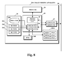
- Fig. 8 is a block diagram illustrating the functional configuration relating to a printer in an image forming apparatus 20A, according to a second embodiment of the present disclosure.
- a button information storage unit 230A is included where the flags F1 to F3 are omitted from the button information storage unit 230 in Fig. 3 , and a pressed-down button information storage unit 240 is included within the DRAM 24.
- the initial value of the pressed-down button information storage unit 240 is NULL or empty.
- a first button information control unit 42A copies an IP address IPAi within the button information storage unit 230A to the pressed-down button information storage unit 240.
- the other configuration elements of the image forming apparatus 20A and the functions thereof are the same as the configuration elements of the image forming apparatus 20 in the first embodiment and the functions thereof.
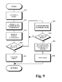
- Fig. 9 is a flowchart illustrating a process performed in the system control unit in the PC 10 and started in response to an occurrence of a time-up event, according to the second embodiment of the present disclosure.
- the first button information control unit 42A In response to a press-down information acquisition request from the PC 10 in a step S11, the first button information control unit 42A sends back the IP address IPAi in the pressed-down button information storage unit 240.
- a step S 15 if the IP address IPAi matches the the IP address IPA of the PC 10, the second button information control unit 57, the process proceeds to a step S17. If the IP address IPAi matches the the IP address IPA of the PC 10, the second button information control unit 57, the process proceeds to a step S21.
- the first button information control unit 42A clears the display of the indicator 260, and clears the content of the pressed-down button information storage unit 240 (NULL or empty).
- processing operations in the first button information control unit 42A and the second button information control unit 57 become easier than in the processing operations in the first embodiment.
- the printing unit may also be a facsimile (including a facsimile modem).
- the image forming apparatus 20 or 20A may also directly detect which of the buttons 261 to 263 is pressed down.
- IP addresses IPA1 to IPA3 illustrated in Fig. 3 or Fig. 8 and the IP-address/user-name table 154 in Fig. 4 may also adopt configurations in which unique device IDs (UDIDs) are used in place of the IP addresses.
- UDIDs unique device IDs
- printer driver 51, the first communication unit 43, and the second communication unit 58 are not limited to the protocols described in the first embodiment, and may also adopt configurations in which another protocol is used.
Landscapes
- Engineering & Computer Science (AREA)
- Theoretical Computer Science (AREA)
- Physics & Mathematics (AREA)
- Human Computer Interaction (AREA)
- General Engineering & Computer Science (AREA)
- General Physics & Mathematics (AREA)
- Mathematical Physics (AREA)
- Accessory Devices And Overall Control Thereof (AREA)
- Facsimiles In General (AREA)
Abstract
Description
- Unless otherwise indicated herein, the description in this field section or the background section is not prior art to the claims in this application and is not admitted to be prior art by inclusion in this section. The present disclosure generally relates to an image forming system, an image forming apparatus, and an image forming method, for realizing a box print by the image forming apparatus having no auxiliary storage device.
- A typical image forming apparatus includes a hard disk (HDD) serving as an auxiliary storage device, and has a box print function. A box, as defined in this disclosure, is a virtual storage area within the auxiliary storage device that may store any number of document files and a print job. The box print function executes a print job stored within the box, and printing is carried out by an instruction via a printer driver, a fax driver, an operation panel of the personal computer, or the like.
- However, it may be difficult for an inexpensive image forming apparatus to realize the box print function, since inexpensive image forming apparatuses commonly have no HDD and typically have a small memory capacity.
- The present disclosure relates to an image forming system, an image forming apparatus, and an image forming method that realizes a box print by the image forming apparatus having no auxiliary storage device.
- A preferred image forming system of the present disclosure includes an image forming apparatus coupled to a network and an information processing apparatus coupled to the network.
- The image forming apparatus includes a button, a memory device, a printing unit including a printer or a facsimile machine, and a first control unit.
- The first control unit is configured to store, in the memory device, an information processing apparatus identifier that is assigned to the button. The first control unit is also configured to transmit, to the information processing apparatus, press-down information including the information processing apparatus identifier corresponding to the button that is pressed-down, in response to a request for the press-down information that is received from the information processing apparatus via the network. The first control unit is further configured to cause the printing unit to print, on a sheet, an image based on print job data that is received from the information processing apparatus via the network.
- The information processing apparatus includes an auxiliary storage device, an input unit, a printing unit driver including a printer driver or a facsimile driver, a spooler, and a second control unit.
- The second control unit is configured to periodically transmit the request for the press-down information to the image forming apparatus via the network, in response to a print-start instruction via at least one of the input unit or the printing unit driver. The second control unit is also configured to determine whether or not the information processing apparatus identifier in the press-down information that is received from the image forming apparatus matches with the information processing apparatus identifier of the information processing apparatus. The second control unit is further configured to transmit the print job data specified by at least one of the input unit or the printing unit driver to the image forming apparatus via the spooler if the information processing apparatus identifier in the press-down information that is received from the image forming apparatus matches the information processing apparatus identifier of the information processing apparatus.
- Additional features and advantages are described herein, and will be apparent from the following Detailed Description and the figures.
- All drawings are intended to illustrate some aspects and examples of the present disclosure. The drawings described are only schematic and are non-limiting, and are not necessarily drawn to scale.
-
Fig. 1 is a schematic diagram illustrating a configuration of an image forming system according to a first embodiment of the present disclosure. -
Fig. 2 is a block diagram illustrating hardware configurations of an information processing apparatus (e.g. a PC) and an image forming apparatus in the image forming system. -
Fig. 3 is a block diagram illustrating a functional configuration relating to a printer in the image forming apparatus. -
Fig. 4 is a block diagram illustrating a functional configuration relating to print of the PC. -
Fig. 5 is a schematic diagram illustrating a job box screen displayed by a print manager before start of printing. -
Fig. 6 is a flowchart illustrating process performed by a UI unit and a system control unit in the PC in response to an operation of a user during display of the job box screen. -
Fig. 7 is a flowchart illustrating process performed in the system control unit in the PC and started in response to an occurrence of a time-up event; -
Fig. 8 is a block diagram illustrating a functional configuration relating to a printer in the image forming apparatus, according to a second embodiment of the present disclosure. -
Fig. 9 is a flowchart illustrating process performed in the system control unit in the PC and started in response to an occurrence of a time-up event, according to the second embodiment of the present disclosure. - Various embodiments are described below with reference to the figures. It should be understood, however, that numerous variations from the depicted arrangements and functions are possible while remaining within the scope and spirit of the claims. For instance, one or more elements may be added, removed, combined, distributed, substituted, re-positioned, re-ordered, and/or otherwise changed. Further, where this description refers to one or more functions being implemented on and/or by one or more devices, one or more machines, and/or one or more networks, it should be understood that one or more of such entities could carry out one or more of such functions by themselves or in cooperation, and may do so by application of any suitable combination of hardware, firmware, and/or software. For instance, one or more processors may execute one or more sets of programming instructions as at least part of carrying out one or more of the functions described herein.
-
-
Fig. 1 is a schematic diagram illustrating the configuration of an image forming system according to a first embodiment of the present disclosure. - In the
image forming system 100, personal computers (PCs) 10-1 to 10-N serving as information processing apparatuses, whose number is N, and animage forming apparatus 20 are coupled owing to anetwork 30. In particular, theimage forming apparatus 20 is inexpensive, and has no auxiliary storage device. -
Fig. 2 is a block diagram illustrating the hardware configurations of thePC 10 and theimage forming apparatus 20 in theimage forming system 100. - The PC 10 is a personal computer, and a central processing unit (CPU) 11 is coupled to a programmable read only memory (PROM) 13, a dynamic random access memory (DRAM) 14, an
auxiliary storage device 15, a network interface card (NIC) 16, and an input-output (I/O)device 17 via aninterface 12. InFig. 2 ,interface 12 may be any type of interface that may be used to allow communication among theCPU 11, the PROM 13, theDRAM 14, theNIC 16, and the I/O device 17. - The PROM 13 is, for example, a flash memory device, and a basic input/output system (BIOS) may be stored therein. The
DRAM 14 is used as a main storage device. An operating system (OS) and various kinds of drivers and application are stored in theauxiliary storage device 15. - In the
image forming apparatus 20, via aninterface 22, aCPU 21 is coupled to aPROM 23, aDRAM 24, anetwork interface 25, anoperation panel 26, ascanner 27, aprinter 28, a facsimile (FAX)modem 29, and anauto sheet feeder 2A. InFig. 2 ,interface 22 may be any type of interface that may be used to allow communication among theCPU 11, the PROM 13, theDRAM 14, theNIC 16, and the I/O device 17.. - The
PROM 23 is, for example, a flash memory device, and may store therein a BIOS, an OS, various kinds of drivers, and applications that run on the image forming apparatus. TheDRAM 24 is used as a main storage device. Thenetwork interface 25 is coupled to thenetwork 30. Thescanner 27 is used for digitizing an image on a paper medium, and the file thereof may be used for printing, facsimile transmission, or file transmission. Theprinter 28 includes a print engine, a paper feeding unit, a transport unit, and a paper ejection unit, which perform various tasks to paper. In addition to this, bitmap data stored on theDRAM 24 is supplied to theprinter 28, and theprinter 28 forms an electrostatic latent image on a photoconductive drum on the basis of this data, develops this image using toner, transfers and fixes a toner image to a sheet of paper, and ejects the sheet of paper. -
Fig. 3 is a block diagram illustrating the functional configuration relating to theprinter 28 in theimage forming apparatus 20. - A
first control unit 40 includes aprinter control unit 41 for theprinter 28, and a first buttoninformation control unit 42 for theoperation panel 26 and a buttoninformation storage unit 230 within thePROM 23. - The
operation panel 26 includesbuttons 261 to 263 used for starting the execution of a print function, and anindicator 260 displaying the button name of a button pressed down from among thebuttons 261 to 263. - The button
information storage unit 230 stores therein, as button information: flags F1 to F3 indicating whether or not thebuttons 261 to 263 have been pressed down, respectively; IP addresses IPA1 to IPA3 serving as PC identifiers assigned to thebuttons 261 to 263, respectively; and box names (BOX 1 to BOX 3) assigned to thebuttons 261 to 263, respectively. - When a button 26i (i: one of 1 to 3) has been pressed down, the first button
information control unit 42 refers to the buttoninformation storage unit 230, and causes theindicator 260 to display the box name, "BOX i", thereof and sets a flag Fi within the buttoninformation storage unit 230. In addition, in response to print termination from theprinter control unit 41, the first buttoninformation control unit 42 resets the flag Fi that is displayed in theindicator 260 and corresponds to the "BOX i", and clears theindicator 260. - A
first communication unit 43 includes thenetwork interface 25 inFig. 2 and a communication protocol stack for the OS. The communication protocol stack includes a TCP/IP unit and a UDP/IP unit. Thefirst communication unit 43 individually sorts pieces of information received from a TCP/IP unit and a UDP/IP unit in the PC 10, into theprinter control unit 41 and the first buttoninformation control unit 42. - The TCP/IP unit in the
first communication unit 43 receives job data from a spooler in thePC 10. In addition, the UDP/IP unit in thefirst communication unit 43 receives, from thePC 10, a registration request for the above-mentioned IP addresses IPA1 to IPA3 and box names. The registration request is based on a Simple Network Management Protocol (SNMP) protocol. In addition, the UDP/IP unit in thefirst communication unit 43 receives a press-down information acquisition request and sends back, to thePC 10, the button information from the first buttoninformation control unit 42, the button information corresponding to this request and being based on the SNMP protocol. - The first button
information control unit 42 includes an SNMP agent on thefirst communication unit 43, and control programs on theoperation panel 26 and the buttoninformation storage unit 230, which serve as processing targets. The buttoninformation storage unit 230 is a portion of a management information base (MIB). -
Fig. 4 is a block diagram illustrating the functional configuration relating to print of thePC 10.Fig. 5 is a schematic diagram illustrating ajob box screen 53 displayed by a print manager before the start of printing. -
Blocks 151 to 154 inFig. 4 are stored within theauxiliary storage device 15 inFig. 2 . Thejob boxes 151 to 153 are folders for storing print job files, and thejob boxes 151 to 153 correspond to thebuttons 261 to 263 inFig. 3 , respectively. An IP-address/user-name table 154 indicates the IP address and the user name of each of the PCs 10-1 to 10-N. - The I/
O device 17 includes a display device 170 and aninput device 171. Theinput device 171 includes, for example, a keyboard and a pointing device. - A user may activate a
document creation application 50 and create a document. Then, the user may select a print menu and activate a print manager in the OS, where the print manager is called via aprinter driver 51. The print manager causes a user interface (UI)unit 52 to display a print dialog (not illustrated) in the display device 170. The user may operate theinput device 171, and set job information such as a page size, single-side/double-side printing, and the number of print copies. When a setting item called "job box" has been selected in the print dialog, such ajob box screen 53 as illustrated inFig. 5 is displayed in the display device 170. - A
second control unit 54 is a box print tool cooperating with theprinter driver 51 and theuser interface unit 52. Thesecond control unit 54 includes asystem control unit 55 controlling the units withinPC 10, ajob control unit 56 controlling a box print job, and a second buttoninformation control unit 57 controlling the button information of theimage forming apparatus 20. - In response to an operation performed on the
input device 171 by the user, the user interface (UI)unit 52 causes the display device 170 to display a menu relating to a print function. In each menu, in response to an operation performed on theinput device 171 by the user, theuser interface unit 52 notifies thesystem control unit 55 of an instruction, a setting value (selection) which has been input, and thesystem control unit 55 performs process according to this. - In the same way as the
first communication unit 43 inFig. 3 , asecond communication unit 58 includes thenetwork interface 16 inFig. 2 and a communication protocol stack for the OS. This communication protocol stack includes a TCP/IP unit and a UDP/IP unit. Thesecond communication unit 58 supplies, to the second buttoninformation control unit 57, information received from the UDP/IP unit in theimage forming apparatus 20. - The second button
information control unit 57 includes an SNMP manager on thesecond communication unit 58, and a control program on thesystem control unit 55. -
Fig. 6 is a flowchart illustrating process performed by theUI unit 52 and thesystem control unit 55 in thePC 10 in response to an operation of a user during display of thejob box screen 53 before the user presses down one of thebuttons 261 to 263 in theimage forming apparatus 20. - Numeric characters, 1 to 3, in a "SELECTION" field in a left column on the
job box screen 53 coincide with the identifiers of thebuttons 261 to 263 in theimage forming apparatus 20, respectively. Immediately before thejob box screen 53 is displayed, and in response to a notice of the job box selection from theuser interface unit 52, thesystem control unit 55 requests the first buttoninformation control unit 42 in theimage forming apparatus 20 to acquire press-down information, via the second buttoninformation control unit 57. In response to this, the first buttoninformation control unit 42 sends back the content of the buttoninformation storage unit 230 to thesystem control unit 55 via the second buttoninformation control unit 57. Thesystem control unit 55 reflects this button information into thejob box screen 53 via theuser interface unit 52. - In a step S0 the user operates the
input device 171 to display a box name in a "NAME" field on thejob box screen 53. The user points to anarrow icon 59 in a "HOLDER" field, and causes a drop-down list coupled to a user name in the IP-address/user-name table 154. By selecting a user name, the user selects an IP address serving as the identifier of thePC 10. Next, when the user has pressed down aregistration button 60, theuser interface unit 52 notifies thesystem control unit 55 of this. In response to this, thesystem control unit 55 specifies button information including a box name and an IP address on the IP-address/user-name table 154, where the IP address corresponds to a user name with respect to each of button identifiers i=1 to 3 in the "selection" field, and instructs the second buttoninformation control unit 57 to perform a button setting. In response to this, the second buttoninformation control unit 57 transmits a button setting request for the button information, to the first buttoninformation control unit 42 via thecommunication unit 58 and thefirst communication unit 43 in theimage forming apparatus 20. - In response to the above-described transmission, the first button
information control unit 42 overwrites and sets a box name within the buttoninformation storage unit 230 with "BOX i" with respect to each of i=1 to 3, the box name corresponding to the button identifier i. The first buttoninformation control unit 42 overwrites and sets the IP address to an IP address IPAi. - In a step S1, the user double-clicks the box name, "BOX i", and causes a path input field (not illustrated) to be displayed. The user inputs and confirms, in the path input field, the path of the "BOX i" within the
auxiliary storage device 15. Theuser interface unit 52 notifies thesystem control unit 55 of the input of the path. In response to the notification, thesystem control unit 55 creates, as "BOX i", a folder for this path within theauxiliary storage device 15. - In
Fig. 5 , the user clicks aradio button 61 to select a box 15i (i=1 inFig. 5 ), and presses down aprint button 62. InFig. 4 , on the basis of document data, thedocument creation application 50 calls afunction 63 within the graphics device interface (GDI) library of WINDOWS® (registered trademark). Via theprinter driver 51, theGDI function 63 converts the document data into page description language (PDL) data interpretable by theimage forming apparatus 20. - The
job control unit 56 converts the job information into a printer job language (PJL) command. Thejob control unit 56 adds the job information to the PDL data, stores the job information within the selected box 15i as a job file, and transfers control to thesystem control unit 55. Thesystem control unit 55 stores therein the path of this job file as a path selected by the user. In addition, thesystem control unit 55 activates a timer T. - The timer T includes a hardware timer within the
CPU 11 inFig. 2 , which the software interval timer of the OS utilizes. Every time a predetermined time interval has elapsed, the timer T causes a time-up event to occur for thesystem control unit 55. -
Fig. 7 is a flowchart illustrating process performed in thesystem control unit 55 in thePC 10 and started in response to an occurrence of a time-up event. - In a step S10, the
system control unit 55 invalidates the timer T, and suppresses the occurrence of a time-up event. - In a step S11, via the second button
information control unit 57, thesystem control unit 55 instructs the second buttoninformation control unit 57 to acquire the button information. In response to this instruction, the second buttoninformation control unit 57 requests button information from the first buttoninformation control unit 42 in theimage forming apparatus 20 via thesecond communication unit 58 and thenetwork 30. - In a step S12, the second button
information control unit 57 receives the button information from the first buttoninformation control unit 42 via thesecond communication unit 58. - The second button
information control unit 57 repeats processing operations ranging from a step S13 to a step S16 with respect to each of i=1 to 3 of the flag Fi and the IP address IPAi that serve as the button information, until affirmative determination is performed in thestep S 15. - In the steps S14 and S15, if the Fi='1' and the IP address IPAi=
PC 10, the process proceeds to a step S17. In addition to this, if, with respect to all of i=1 to 3, this condition IPAi=PC 10 is not satisfied, the process proceeds to a step S21. - In the step S17, the second button
information control unit 57 returns control to thesystem control unit 55. Thesystem control unit 55 requests theprinter control unit 41 to confirm whether or not theprinter 28 is in a ready state, via the second buttoninformation control unit 57, thecommunication unit 58, and the first buttoninformation control unit 42 in theimage forming apparatus 20. Theprinter control unit 41 confirms whether or not theprinter 28 is in a ready state, and theprinter control unit 41 sends back the result thereof to thesystem control unit 55 via the first buttoninformation control unit 42 and the second buttoninformation control unit 57. - In the
step S 19, when it is indicated that theprinter 28 is in a ready state, thesystem control unit 55 transfers, to aspooler 64, the job file of the selected path within the box BOX i corresponding to the Fi='1' in the step S14. Thespooler 64 transmits job files in the reception order thereof, to theprinter control unit 41 via thecommunication unit 58 and thefirst communication unit 43 in theimage forming apparatus 20. - When the
printer 28 is not in a ready state, thesystem control unit 55 returns to the step S17. Using another timer, this loop processing operation in the steps S17 and S18 is performed periodically. - The
printer control unit 41 stores the received job file in a buffer area within theDRAM 24. Then, in accordance with a buffer size, having converted PDL data into an intermediate language in units of pages or in units of blocks into which a page is divided, theprinter control unit 41 subjects the data to bit map expansion, and sends the data to the print engine of theprinter 28. By controlling the paper feeding/ejection mechanism of theprinter 28, theprinter control unit 41 causes an image to be formed on a sheet of paper, and causes this sheet of paper to be ejected. - When printing for all pages has been completed, the
printer control unit 41 resets the flag Fi corresponding to the box name, "BOX i", displayed in theindicator 260, and clears this display. - In a step S20, the timer T is stopped, the path name of the stored job file is deleted, and the process is returned.
- In the step S21, the timer T is validated, the suppression of the occurrence of the time-up event is cancelled, and the process is returned.
- In
Fig. 5 , if thesave button 65 has been pressed down instead of theprint button 62, a job file is saved within the job box 15i in the same way as described above. However, when the job file is saved within the job box 15i, the timer T is not activated, and printing is not performed. - In
Fig. 5 , if anopen button 66 is pressed down and a box is opened after the job box 15i has been selected, a job file within the box may be directly selected. Then, when theprint button 62 is pressed down theimage forming apparatus 20 is put into a print-start standby state. When the button 26i in theimage forming apparatus 20 is pressed down, the path of this job file is stored, and the printing of the selected job file is performed in the same way as described above. - According to the present first embodiment, when the user has put the
image forming apparatus 20 into a print-start standby state by selecting a job file stored in theauxiliary storage device 15 in thePC 10, and pressed down a button (from among thebuttons 261 to 263 in the image forming apparatus 20) corresponding to a box including the selected job file, thePC 10 transmits the job file to theimage forming apparatus 20 via thespooler 64, and print execution is started. Even if theimage forming apparatus 20 has no auxiliary storage device, it may be possible to realize the same box print utilizing another image forming apparatus that has an auxiliary storage device. - In addition, it may be possible for the user to set, from the
PC 10 via thenetwork 30, an association between one or more selected from among thebuttons 261 to 263 in theimage forming apparatus 20 and thePC 10. Even if the function of theimage forming apparatus 20 is enhanced as described above, it may be possible to further simplify the configuration thereof and achieve price reduction. -
Fig. 8 is a block diagram illustrating the functional configuration relating to a printer in an image forming apparatus 20A, according to a second embodiment of the present disclosure. - In the second embodiment, a button
information storage unit 230A is included where the flags F1 to F3 are omitted from the buttoninformation storage unit 230 inFig. 3 , and a pressed-down buttoninformation storage unit 240 is included within theDRAM 24. The initial value of the pressed-down buttoninformation storage unit 240 is NULL or empty. In response to a button 26i pressed down by a user, a first buttoninformation control unit 42A copies an IP address IPAi within the buttoninformation storage unit 230A to the pressed-down buttoninformation storage unit 240. In addition, the other configuration elements of the image forming apparatus 20A and the functions thereof are the same as the configuration elements of theimage forming apparatus 20 in the first embodiment and the functions thereof. -
Fig. 9 is a flowchart illustrating a process performed in the system control unit in thePC 10 and started in response to an occurrence of a time-up event, according to the second embodiment of the present disclosure. - In response to a press-down information acquisition request from the
PC 10 in a step S11, the first buttoninformation control unit 42A sends back the IP address IPAi in the pressed-down buttoninformation storage unit 240. - In a
step S 15, if the IP address IPAi matches the the IP address IPA of thePC 10, the second buttoninformation control unit 57, the process proceeds to a step S17. If the IP address IPAi matches the the IP address IPA of thePC 10, the second buttoninformation control unit 57, the process proceeds to a step S21. - When printing for all pages has been completed, the first button
information control unit 42A clears the display of theindicator 260, and clears the content of the pressed-down button information storage unit 240 (NULL or empty). - The other control of the flowchart illustrated in
Fig. 9 is the same as the control of the flowchart illustrated inFig. 6 in the first embodiment. - According to the present second embodiment, processing operations in the first button
information control unit 42A and the second buttoninformation control unit 57 become easier than in the processing operations in the first embodiment. - While various aspects and embodiments have been disclosed herein, other aspects and embodiments are possible. Other designs may be used in which the above-described components are each present.
- For example, while, in the first and second embodiments, a case has been described where the printing unit is a printer, the printing unit may also be a facsimile (including a facsimile modem).
- In addition, in the first and second embodiments, when the steps S17 and S18 are omitted, the time-up interval of the timer T is shortened, the flags F1 to F3 are not used, and the
image forming apparatus 20 has received the press-down information acquisition request, theimage forming apparatus 20 or 20A may also directly detect which of thebuttons 261 to 263 is pressed down. - In addition, the IP addresses IPA1 to IPA3 illustrated in
Fig. 3 orFig. 8 and the IP-address/user-name table 154 inFig. 4 may also adopt configurations in which unique device IDs (UDIDs) are used in place of the IP addresses. - In addition, the
printer driver 51, thefirst communication unit 43, and thesecond communication unit 58 are not limited to the protocols described in the first embodiment, and may also adopt configurations in which another protocol is used. - It should be understood that various changes and modifications to the embodiments described herein will be apparent to those skilled in the art. Such changes and modifications may be made without departing from the scope of the present subject matter and without diminishing its intended advantages. Additionally, any combination of the elements within the previously described image forming apparatus and information processing apparatus may be added or removed without departing from the scope of the claims. It is therefore intended that such changes and modifications be covered by the appended claims.
Claims (18)
- An image forming system 100 comprising:an image forming apparatus 20 coupled to a network 30, wherein the image forming apparatus includes a button 261, a memory device 23, a printing unit including a printer 28 or a facsimile 29, and a first control unit 40; andan information processing apparatus 10 coupled to the network, wherein the information processing apparatus includes an auxiliary storage device 15, an input unit 171, a printing unit driver including a printer driver 51 or a facsimile driver, a spooler 64, and a second control unit 50;wherein the first control unit is configured to:i) store, in the memory device, an information processing apparatus identifier that is assigned to the button,ii) transmit, to the information processing apparatus, press-down information including the information processing apparatus identifier corresponding to the button, in response to a request for the press-down information that is received from the information processing apparatus via the network, andiii) cause the printing unit to print, on a sheet, an image based on print job data that is received from the information processing apparatus via the network; andwherein the second control unit is configured toi) periodically transmit the request for the press-down information to the image forming apparatus via the network, in response to a print-start instruction from the input unit or the printing unit driver,ii) determine whether or not the information processing apparatus identifier in the press-down information that is received from the image forming apparatus 20 matches the information processing apparatus identifier of the information processing apparatus, andiii) transmit the print job data specified the input unit or the printing unit driver to the image forming apparatus via the spooler if the information processing apparatus identifier in the press-down information that is received from the image forming apparatus matches the information processing apparatus identifier of the information processing apparatus.
- The image forming system 100 according to Claim 1,
wherein the press-down information includes a flag indicating whether or not the button 261 is pressed down. - The image forming system 100 according to Claims 1 and 2, wherein
wherein the second control unit 50 is further configured to transmit, to the first control unit 40, an information processing apparatus identifier that is received from the input unit 171, and
wherein the first control unit is further configured to assign, to the button 261, the information processing apparatus identifier that is received from the input unit. - The image forming system 100 according to Claims 1, 2, and 3, wherein the image forming apparatus 20 further includes an indicator for displaying a name of the button 261.
- The image forming system 100 according to any of the previous Claims, wherein the image forming apparatus 20 further includes a communication unit 43 for receiving the print job data from the information processing apparatus 10 and printing the image data of the document image on the sheet based on the print job data.
- The image forming system 100 according to any of the previous Claims, wherein the information processing apparatus 10 further includes a spooler 64 for receiving a job file and transmitting the job file to the printing unit.
- An image forming apparatus 20 coupled to an information processing apparatus 10 and a network 30, the image forming apparatus comprising a button 261, a memory device 23, a printing unit including a printer 28 or a facsimile 29, and a control unit, wherein the control unit is configured to:i) store, in the memory device 23, an information processing apparatus identifier that is assigned to the button 261;ii) transmit, to the information processing apparatus, press-down information including the information processing apparatus identifier corresponding to the button 261, in response to a periodic request for the press-down information that is received from the information processing apparatus via the network; andiii) cause the printing unit to print, on a sheet, an image based on print job data that is specified by the information processing apparatus and transmitted to the image forming apparatus via the network, if, in the information processing apparatus 10, it is determined the information processing apparatus identifier in the press-down information matches with the information processing apparatus identifier of the information processing apparatus 10 and if the information processing apparatus identifier in the press-down information that is received from the image forming apparatus 20 matches the information processing apparatus identifier of the information processing apparatus 10.
- The image forming apparatus 20 according to Claim 7,
wherein the press-down information includes a flag indicating whether or not the button 261 is pressed down. - The image forming apparatus 20 according to Claims 7 and 8,
wherein the control unit is further configured to receive an information processing apparatus identifier that is transmitted from the information processing apparatus 10, and
wherein the control unit is further configured to assign, to the button 261, the information processing apparatus identifier that is transmitted from the information processing apparatus 10. - The image forming apparatus 20 according to Claims 7, 8 and 9, further comprising an indicator for displaying a name of the button 261.
- The image forming apparatus 20 according to Claims 7-10, further comprising a communication unit 43 for receiving the print job data from the information processing apparatus 10 and printing the image data of the document image on the sheet based on the print job data.
- The image forming apparatus 20 according to Claims 7-11, wherein the information processing apparatus 10 further includes a spooler 64 for receiving a job file and transmitting the job file to the printing unit.
- An image forming method performed by an image forming system 100 including an image forming apparatus 20 coupled to a network 30 and an information processing apparatus 10 coupled to the network 30, the image forming method comprising:via the image forming apparatus 20,i) storing, in a memory device 23, an information processing apparatus identifier that is assigned to a button 261 of the image forming apparatus 20,ii) transmitting, to the information processing apparatus 10, press-down information including the information processing apparatus identifier corresponding to the button 261, in response to a request for the press-down information that is received from the information processing apparatus 10 via the network 30,iii) printing, on a sheet, an image based on print job data that is received from the information processing apparatus 10 via the network 30; andvia the information processing apparatus 10,i) periodically transmitting the request for the press-down information to the image forming apparatus 20 via the network 30, in response to a print-start instruction,ii) determining whether or not the information processing apparatus identifier in the press-down information that is received from the image forming apparatus 20 matches with the information processing apparatus identifier of the information processing apparatus, andiii) transmitting the print job data specified by the information processing apparatus 10 to the image forming apparatus 20 if the information processing apparatus identifier in the press-down information that is received from the image forming apparatus 20 matches the information processing apparatus identifier of the information processing apparatus 10.
- The image forming method according to Claims 13, wherein
the press-down information includes a flag indicating whether or not a button 261 is pressed down. - The image forming method according to Claims 13 and 14, further comprising:via the information processing apparatus 10,iv) transmitting, to the image forming apparatus 20, an information processing apparatus identifier that is transmitted from the information processing apparatus 10; andvia the image forming apparatus 20,iv) assigning, to the button 261, the information processing apparatus identifier that is transmitted from the information processing apparatus 10.
- The image forming method according to Claims 13, 14, and 15, further comprising,
via the image forming apparatus 20,v) displaying, via an indicator, a name of a button 261. - The image forming method according to Claims 13-16, further comprising, via the image forming apparatus 20,vi) receiving, via a communication unit 43, the print job data from the information processing apparatus 10 and printing the image data of the document image on the sheet based on the print job data.
- The image forming method according to Claims 13-17, further comprising, via the information processing apparatus 10,v) receiving, via a spooler 64, a job file; andvi) transmitting, via the spooler 64, the job file to the printing unit.
Applications Claiming Priority (2)
| Application Number | Priority Date | Filing Date | Title |
|---|---|---|---|
| JP2012286963A JP5808732B2 (en) | 2012-12-28 | 2012-12-28 | Image forming system and image forming apparatus and information processing apparatus constituting the same |
| US14/138,778 US9025190B2 (en) | 2012-12-28 | 2013-12-23 | Box print realized by image forming apparatus having no auxiliary storage device |
Publications (2)
| Publication Number | Publication Date |
|---|---|
| EP2750023A1 true EP2750023A1 (en) | 2014-07-02 |
| EP2750023B1 EP2750023B1 (en) | 2020-07-29 |
Family
ID=50028699
Family Applications (1)
| Application Number | Title | Priority Date | Filing Date |
|---|---|---|---|
| EP13199580.5A Active EP2750023B1 (en) | 2012-12-28 | 2013-12-24 | Box print realized by image forming apparatus having no auxiliary storage device |
Country Status (1)
| Country | Link |
|---|---|
| EP (1) | EP2750023B1 (en) |
Cited By (2)
| Publication number | Priority date | Publication date | Assignee | Title |
|---|---|---|---|---|
| US10090633B2 (en) | 2012-12-06 | 2018-10-02 | Trumpf Laser- Und Systemtechnik Gmbh | Diffusion cooled gas laser arrangement and method for setting the discharge distribution in the case of diffusion cooled gas laser arrangement |
| CN109460195A (en) * | 2018-09-29 | 2019-03-12 | 先临三维科技股份有限公司 | A kind of 3D printing system based on local area network communication, control method and 3D printer |
Citations (2)
| Publication number | Priority date | Publication date | Assignee | Title |
|---|---|---|---|---|
| US20010038462A1 (en) * | 1998-03-19 | 2001-11-08 | Teeuwen Peter Johannes Hendrikus Maria | Interactive printing with a plurality of printer devices |
| US20050068564A1 (en) * | 2003-09-30 | 2005-03-31 | Ferlitsch Andrew R. | Systems and methods for providing interactive printing with job data pull |
-
2013
- 2013-12-24 EP EP13199580.5A patent/EP2750023B1/en active Active
Patent Citations (2)
| Publication number | Priority date | Publication date | Assignee | Title |
|---|---|---|---|---|
| US20010038462A1 (en) * | 1998-03-19 | 2001-11-08 | Teeuwen Peter Johannes Hendrikus Maria | Interactive printing with a plurality of printer devices |
| US20050068564A1 (en) * | 2003-09-30 | 2005-03-31 | Ferlitsch Andrew R. | Systems and methods for providing interactive printing with job data pull |
Cited By (2)
| Publication number | Priority date | Publication date | Assignee | Title |
|---|---|---|---|---|
| US10090633B2 (en) | 2012-12-06 | 2018-10-02 | Trumpf Laser- Und Systemtechnik Gmbh | Diffusion cooled gas laser arrangement and method for setting the discharge distribution in the case of diffusion cooled gas laser arrangement |
| CN109460195A (en) * | 2018-09-29 | 2019-03-12 | 先临三维科技股份有限公司 | A kind of 3D printing system based on local area network communication, control method and 3D printer |
Also Published As
| Publication number | Publication date |
|---|---|
| EP2750023B1 (en) | 2020-07-29 |
Similar Documents
| Publication | Publication Date | Title |
|---|---|---|
| JP4240690B2 (en) | Information processing apparatus, information processing method, information processing system, and recording medium | |
| JP2026066288A (en) | Information processing device, control method, and program | |
| EP2494437B1 (en) | Information processing system, print system, and method and program for controlling information processing system | |
| US9442678B2 (en) | Information processing apparatus, information processing system and non-transitory computer-readable information recording medium | |
| US20110063668A1 (en) | Printing control apparatus, printing control method, and storage medium | |
| EP2388685B1 (en) | Information processing apparatus and control method thereof, and storage medium | |
| US10671329B2 (en) | Image forming apparatus for generating raster image data based on PDL data, using general purpose processor and raster image processor and image forming method | |
| US12430083B2 (en) | Information processing apparatus, control method therefor, and non-transitory computer-readable storage medium | |
| US20250199741A1 (en) | Information processing apparatus and method for controlling information processing apparatus | |
| US9025190B2 (en) | Box print realized by image forming apparatus having no auxiliary storage device | |
| JP2019040528A (en) | Server apparatus, control method therefor, program, and printing system | |
| EP2750023B1 (en) | Box print realized by image forming apparatus having no auxiliary storage device | |
| US20120057199A1 (en) | Image forming system, server, and image forming apparatus | |
| EP2811729B1 (en) | Scanner-driven push operation realized by image forming apparatus having no auxiliary storage device | |
| US7726757B2 (en) | Image forming apparatus and information processing method | |
| US11704082B2 (en) | Print server generating image data after image processing in accordance with print sheet orientation of paper feed source | |
| JP2013156807A (en) | Network-based event notification system | |
| US20250208800A1 (en) | Printing apparatus, print server, information processing apparatus, and control methods thereof | |
| US20250208801A1 (en) | Printing apparatus and control methods thereof | |
| JPH118727A (en) | Image processing apparatus and information processing system | |
| CN121752987A (en) | Information processing program and information processing apparatus | |
| JP2026075764A (en) | Printing apparatus, printing system, control method and program thereof | |
| JP2014130432A (en) | Image forming system, and image forming apparatus and information processing apparatus constituting the same |
Legal Events
| Date | Code | Title | Description |
|---|---|---|---|
| 17P | Request for examination filed |
Effective date: 20131224 |
|
| AK | Designated contracting states |
Kind code of ref document: A1 Designated state(s): AL AT BE BG CH CY CZ DE DK EE ES FI FR GB GR HR HU IE IS IT LI LT LU LV MC MK MT NL NO PL PT RO RS SE SI SK SM TR |
|
| AX | Request for extension of the european patent |
Extension state: BA ME |
|
| PUAI | Public reference made under article 153(3) epc to a published international application that has entered the european phase |
Free format text: ORIGINAL CODE: 0009012 |
|
| STAA | Information on the status of an ep patent application or granted ep patent |
Free format text: STATUS: EXAMINATION IS IN PROGRESS |
|
| 17Q | First examination report despatched |
Effective date: 20180223 |
|
| GRAP | Despatch of communication of intention to grant a patent |
Free format text: ORIGINAL CODE: EPIDOSNIGR1 |
|
| STAA | Information on the status of an ep patent application or granted ep patent |
Free format text: STATUS: GRANT OF PATENT IS INTENDED |
|
| INTG | Intention to grant announced |
Effective date: 20200221 |
|
| GRAS | Grant fee paid |
Free format text: ORIGINAL CODE: EPIDOSNIGR3 |
|
| GRAA | (expected) grant |
Free format text: ORIGINAL CODE: 0009210 |
|
| STAA | Information on the status of an ep patent application or granted ep patent |
Free format text: STATUS: THE PATENT HAS BEEN GRANTED |
|
| AK | Designated contracting states |
Kind code of ref document: B1 Designated state(s): AL AT BE BG CH CY CZ DE DK EE ES FI FR GB GR HR HU IE IS IT LI LT LU LV MC MK MT NL NO PL PT RO RS SE SI SK SM TR |
|
| REG | Reference to a national code |
Ref country code: GB Ref legal event code: FG4D |
|
| REG | Reference to a national code |
Ref country code: CH Ref legal event code: EP |
|
| REG | Reference to a national code |
Ref country code: DE Ref legal event code: R096 Ref document number: 602013071075 Country of ref document: DE |
|
| REG | Reference to a national code |
Ref country code: AT Ref legal event code: REF Ref document number: 1296571 Country of ref document: AT Kind code of ref document: T Effective date: 20200815 |
|
| REG | Reference to a national code |
Ref country code: IE Ref legal event code: FG4D |
|
| REG | Reference to a national code |
Ref country code: LT Ref legal event code: MG4D |
|
| REG | Reference to a national code |
Ref country code: NL Ref legal event code: MP Effective date: 20200729 |
|
| REG | Reference to a national code |
Ref country code: AT Ref legal event code: MK05 Ref document number: 1296571 Country of ref document: AT Kind code of ref document: T Effective date: 20200729 |
|
| PG25 | Lapsed in a contracting state [announced via postgrant information from national office to epo] |
Ref country code: LT Free format text: LAPSE BECAUSE OF FAILURE TO SUBMIT A TRANSLATION OF THE DESCRIPTION OR TO PAY THE FEE WITHIN THE PRESCRIBED TIME-LIMIT Effective date: 20200729 Ref country code: ES Free format text: LAPSE BECAUSE OF FAILURE TO SUBMIT A TRANSLATION OF THE DESCRIPTION OR TO PAY THE FEE WITHIN THE PRESCRIBED TIME-LIMIT Effective date: 20200729 Ref country code: GR Free format text: LAPSE BECAUSE OF FAILURE TO SUBMIT A TRANSLATION OF THE DESCRIPTION OR TO PAY THE FEE WITHIN THE PRESCRIBED TIME-LIMIT Effective date: 20201030 Ref country code: BG Free format text: LAPSE BECAUSE OF FAILURE TO SUBMIT A TRANSLATION OF THE DESCRIPTION OR TO PAY THE FEE WITHIN THE PRESCRIBED TIME-LIMIT Effective date: 20201029 Ref country code: HR Free format text: LAPSE BECAUSE OF FAILURE TO SUBMIT A TRANSLATION OF THE DESCRIPTION OR TO PAY THE FEE WITHIN THE PRESCRIBED TIME-LIMIT Effective date: 20200729 Ref country code: FI Free format text: LAPSE BECAUSE OF FAILURE TO SUBMIT A TRANSLATION OF THE DESCRIPTION OR TO PAY THE FEE WITHIN THE PRESCRIBED TIME-LIMIT Effective date: 20200729 Ref country code: NO Free format text: LAPSE BECAUSE OF FAILURE TO SUBMIT A TRANSLATION OF THE DESCRIPTION OR TO PAY THE FEE WITHIN THE PRESCRIBED TIME-LIMIT Effective date: 20201029 Ref country code: SE Free format text: LAPSE BECAUSE OF FAILURE TO SUBMIT A TRANSLATION OF THE DESCRIPTION OR TO PAY THE FEE WITHIN THE PRESCRIBED TIME-LIMIT Effective date: 20200729 Ref country code: AT Free format text: LAPSE BECAUSE OF FAILURE TO SUBMIT A TRANSLATION OF THE DESCRIPTION OR TO PAY THE FEE WITHIN THE PRESCRIBED TIME-LIMIT Effective date: 20200729 Ref country code: PT Free format text: LAPSE BECAUSE OF FAILURE TO SUBMIT A TRANSLATION OF THE DESCRIPTION OR TO PAY THE FEE WITHIN THE PRESCRIBED TIME-LIMIT Effective date: 20201130 |
|
| PG25 | Lapsed in a contracting state [announced via postgrant information from national office to epo] |
Ref country code: IS Free format text: LAPSE BECAUSE OF FAILURE TO SUBMIT A TRANSLATION OF THE DESCRIPTION OR TO PAY THE FEE WITHIN THE PRESCRIBED TIME-LIMIT Effective date: 20201129 Ref country code: LV Free format text: LAPSE BECAUSE OF FAILURE TO SUBMIT A TRANSLATION OF THE DESCRIPTION OR TO PAY THE FEE WITHIN THE PRESCRIBED TIME-LIMIT Effective date: 20200729 Ref country code: RS Free format text: LAPSE BECAUSE OF FAILURE TO SUBMIT A TRANSLATION OF THE DESCRIPTION OR TO PAY THE FEE WITHIN THE PRESCRIBED TIME-LIMIT Effective date: 20200729 Ref country code: PL Free format text: LAPSE BECAUSE OF FAILURE TO SUBMIT A TRANSLATION OF THE DESCRIPTION OR TO PAY THE FEE WITHIN THE PRESCRIBED TIME-LIMIT Effective date: 20200729 |
|
| PG25 | Lapsed in a contracting state [announced via postgrant information from national office to epo] |
Ref country code: NL Free format text: LAPSE BECAUSE OF FAILURE TO SUBMIT A TRANSLATION OF THE DESCRIPTION OR TO PAY THE FEE WITHIN THE PRESCRIBED TIME-LIMIT Effective date: 20200729 |
|
| PG25 | Lapsed in a contracting state [announced via postgrant information from national office to epo] |
Ref country code: IT Free format text: LAPSE BECAUSE OF FAILURE TO SUBMIT A TRANSLATION OF THE DESCRIPTION OR TO PAY THE FEE WITHIN THE PRESCRIBED TIME-LIMIT Effective date: 20200729 Ref country code: EE Free format text: LAPSE BECAUSE OF FAILURE TO SUBMIT A TRANSLATION OF THE DESCRIPTION OR TO PAY THE FEE WITHIN THE PRESCRIBED TIME-LIMIT Effective date: 20200729 Ref country code: CZ Free format text: LAPSE BECAUSE OF FAILURE TO SUBMIT A TRANSLATION OF THE DESCRIPTION OR TO PAY THE FEE WITHIN THE PRESCRIBED TIME-LIMIT Effective date: 20200729 Ref country code: DK Free format text: LAPSE BECAUSE OF FAILURE TO SUBMIT A TRANSLATION OF THE DESCRIPTION OR TO PAY THE FEE WITHIN THE PRESCRIBED TIME-LIMIT Effective date: 20200729 Ref country code: SM Free format text: LAPSE BECAUSE OF FAILURE TO SUBMIT A TRANSLATION OF THE DESCRIPTION OR TO PAY THE FEE WITHIN THE PRESCRIBED TIME-LIMIT Effective date: 20200729 Ref country code: RO Free format text: LAPSE BECAUSE OF FAILURE TO SUBMIT A TRANSLATION OF THE DESCRIPTION OR TO PAY THE FEE WITHIN THE PRESCRIBED TIME-LIMIT Effective date: 20200729 |
|
| REG | Reference to a national code |
Ref country code: DE Ref legal event code: R097 Ref document number: 602013071075 Country of ref document: DE |
|
| PG25 | Lapsed in a contracting state [announced via postgrant information from national office to epo] |
Ref country code: AL Free format text: LAPSE BECAUSE OF FAILURE TO SUBMIT A TRANSLATION OF THE DESCRIPTION OR TO PAY THE FEE WITHIN THE PRESCRIBED TIME-LIMIT Effective date: 20200729 |
|
| PLBE | No opposition filed within time limit |
Free format text: ORIGINAL CODE: 0009261 |
|
| STAA | Information on the status of an ep patent application or granted ep patent |
Free format text: STATUS: NO OPPOSITION FILED WITHIN TIME LIMIT |
|
| PG25 | Lapsed in a contracting state [announced via postgrant information from national office to epo] |
Ref country code: SK Free format text: LAPSE BECAUSE OF FAILURE TO SUBMIT A TRANSLATION OF THE DESCRIPTION OR TO PAY THE FEE WITHIN THE PRESCRIBED TIME-LIMIT Effective date: 20200729 |
|
| 26N | No opposition filed |
Effective date: 20210430 |
|
| REG | Reference to a national code |
Ref country code: CH Ref legal event code: PL |
|
| PG25 | Lapsed in a contracting state [announced via postgrant information from national office to epo] |
Ref country code: SI Free format text: LAPSE BECAUSE OF FAILURE TO SUBMIT A TRANSLATION OF THE DESCRIPTION OR TO PAY THE FEE WITHIN THE PRESCRIBED TIME-LIMIT Effective date: 20200729 Ref country code: MC Free format text: LAPSE BECAUSE OF FAILURE TO SUBMIT A TRANSLATION OF THE DESCRIPTION OR TO PAY THE FEE WITHIN THE PRESCRIBED TIME-LIMIT Effective date: 20200729 |
|
| REG | Reference to a national code |
Ref country code: BE Ref legal event code: MM Effective date: 20201231 |
|
| PG25 | Lapsed in a contracting state [announced via postgrant information from national office to epo] |
Ref country code: LU Free format text: LAPSE BECAUSE OF NON-PAYMENT OF DUE FEES Effective date: 20201224 Ref country code: IE Free format text: LAPSE BECAUSE OF NON-PAYMENT OF DUE FEES Effective date: 20201224 |
|
| PG25 | Lapsed in a contracting state [announced via postgrant information from national office to epo] |
Ref country code: LI Free format text: LAPSE BECAUSE OF NON-PAYMENT OF DUE FEES Effective date: 20201231 Ref country code: CH Free format text: LAPSE BECAUSE OF NON-PAYMENT OF DUE FEES Effective date: 20201231 |
|
| PG25 | Lapsed in a contracting state [announced via postgrant information from national office to epo] |
Ref country code: TR Free format text: LAPSE BECAUSE OF FAILURE TO SUBMIT A TRANSLATION OF THE DESCRIPTION OR TO PAY THE FEE WITHIN THE PRESCRIBED TIME-LIMIT Effective date: 20200729 Ref country code: MT Free format text: LAPSE BECAUSE OF FAILURE TO SUBMIT A TRANSLATION OF THE DESCRIPTION OR TO PAY THE FEE WITHIN THE PRESCRIBED TIME-LIMIT Effective date: 20200729 Ref country code: CY Free format text: LAPSE BECAUSE OF FAILURE TO SUBMIT A TRANSLATION OF THE DESCRIPTION OR TO PAY THE FEE WITHIN THE PRESCRIBED TIME-LIMIT Effective date: 20200729 |
|
| PG25 | Lapsed in a contracting state [announced via postgrant information from national office to epo] |
Ref country code: MK Free format text: LAPSE BECAUSE OF FAILURE TO SUBMIT A TRANSLATION OF THE DESCRIPTION OR TO PAY THE FEE WITHIN THE PRESCRIBED TIME-LIMIT Effective date: 20200729 |
|
| PG25 | Lapsed in a contracting state [announced via postgrant information from national office to epo] |
Ref country code: BE Free format text: LAPSE BECAUSE OF NON-PAYMENT OF DUE FEES Effective date: 20201231 |
|
| P01 | Opt-out of the competence of the unified patent court (upc) registered |
Effective date: 20230420 |
|
| PGFP | Annual fee paid to national office [announced via postgrant information from national office to epo] |
Ref country code: DE Payment date: 20251126 Year of fee payment: 13 |
|
| PGFP | Annual fee paid to national office [announced via postgrant information from national office to epo] |
Ref country code: GB Payment date: 20251119 Year of fee payment: 13 |
|
| PGFP | Annual fee paid to national office [announced via postgrant information from national office to epo] |
Ref country code: FR Payment date: 20251120 Year of fee payment: 13 |