EP2749957A2 - Image forming apparatus - Google Patents
Image forming apparatus Download PDFInfo
- Publication number
- EP2749957A2 EP2749957A2 EP13198960.0A EP13198960A EP2749957A2 EP 2749957 A2 EP2749957 A2 EP 2749957A2 EP 13198960 A EP13198960 A EP 13198960A EP 2749957 A2 EP2749957 A2 EP 2749957A2
- Authority
- EP
- European Patent Office
- Prior art keywords
- measurement
- image
- white reference
- image forming
- color
- Prior art date
- Legal status (The legal status is an assumption and is not a legal conclusion. Google has not performed a legal analysis and makes no representation as to the accuracy of the status listed.)
- Granted
Links
- 238000005259 measurement Methods 0.000 claims abstract description 78
- 238000012937 correction Methods 0.000 claims description 19
- 239000003086 colorant Substances 0.000 claims description 11
- 230000001678 irradiating effect Effects 0.000 claims description 3
- 239000000463 material Substances 0.000 claims description 2
- 238000007599 discharging Methods 0.000 claims 1
- 238000010586 diagram Methods 0.000 description 19
- 238000012545 processing Methods 0.000 description 16
- 238000006243 chemical reaction Methods 0.000 description 14
- 230000003595 spectral effect Effects 0.000 description 9
- 239000000428 dust Substances 0.000 description 6
- 238000000034 method Methods 0.000 description 6
- 239000000126 substance Substances 0.000 description 6
- 238000012546 transfer Methods 0.000 description 6
- 238000012360 testing method Methods 0.000 description 4
- 238000002845 discoloration Methods 0.000 description 3
- 238000007726 management method Methods 0.000 description 3
- 230000007246 mechanism Effects 0.000 description 3
- 230000001419 dependent effect Effects 0.000 description 2
- 238000001514 detection method Methods 0.000 description 2
- 230000000694 effects Effects 0.000 description 2
- 230000006870 function Effects 0.000 description 2
- 230000008569 process Effects 0.000 description 2
- 241000490025 Schefflera digitata Species 0.000 description 1
- 230000015572 biosynthetic process Effects 0.000 description 1
- 238000013440 design planning Methods 0.000 description 1
- 238000011161 development Methods 0.000 description 1
- 238000001035 drying Methods 0.000 description 1
- 238000005265 energy consumption Methods 0.000 description 1
- 238000001704 evaporation Methods 0.000 description 1
- 238000005286 illumination Methods 0.000 description 1
- 239000012535 impurity Substances 0.000 description 1
- 235000015250 liver sausages Nutrition 0.000 description 1
- 238000013507 mapping Methods 0.000 description 1
- 239000002184 metal Substances 0.000 description 1
- 229910052751 metal Inorganic materials 0.000 description 1
- 238000012986 modification Methods 0.000 description 1
- 230000004048 modification Effects 0.000 description 1
- 230000008520 organization Effects 0.000 description 1
- 238000007539 photo-oxidation reaction Methods 0.000 description 1
- 238000003825 pressing Methods 0.000 description 1
- 230000035755 proliferation Effects 0.000 description 1
- 238000009877 rendering Methods 0.000 description 1
- 230000004044 response Effects 0.000 description 1
- 238000000926 separation method Methods 0.000 description 1
- 238000005092 sublimation method Methods 0.000 description 1
Images






Classifications
-
- G—PHYSICS
- G03—PHOTOGRAPHY; CINEMATOGRAPHY; ANALOGOUS TECHNIQUES USING WAVES OTHER THAN OPTICAL WAVES; ELECTROGRAPHY; HOLOGRAPHY
- G03G—ELECTROGRAPHY; ELECTROPHOTOGRAPHY; MAGNETOGRAPHY
- G03G15/00—Apparatus for electrographic processes using a charge pattern
- G03G15/01—Apparatus for electrographic processes using a charge pattern for producing multicoloured copies
-
- G—PHYSICS
- G01—MEASURING; TESTING
- G01J—MEASUREMENT OF INTENSITY, VELOCITY, SPECTRAL CONTENT, POLARISATION, PHASE OR PULSE CHARACTERISTICS OF INFRARED, VISIBLE OR ULTRAVIOLET LIGHT; COLORIMETRY; RADIATION PYROMETRY
- G01J3/00—Spectrometry; Spectrophotometry; Monochromators; Measuring colours
- G01J3/46—Measurement of colour; Colour measuring devices, e.g. colorimeters
-
- G—PHYSICS
- G03—PHOTOGRAPHY; CINEMATOGRAPHY; ANALOGOUS TECHNIQUES USING WAVES OTHER THAN OPTICAL WAVES; ELECTROGRAPHY; HOLOGRAPHY
- G03G—ELECTROGRAPHY; ELECTROPHOTOGRAPHY; MAGNETOGRAPHY
- G03G15/00—Apparatus for electrographic processes using a charge pattern
- G03G15/50—Machine control of apparatus for electrographic processes using a charge pattern, e.g. regulating differents parts of the machine, multimode copiers, microprocessor control
- G03G15/5062—Machine control of apparatus for electrographic processes using a charge pattern, e.g. regulating differents parts of the machine, multimode copiers, microprocessor control by measuring the characteristics of an image on the copy material
-
- H—ELECTRICITY
- H04—ELECTRIC COMMUNICATION TECHNIQUE
- H04N—PICTORIAL COMMUNICATION, e.g. TELEVISION
- H04N1/00—Scanning, transmission or reproduction of documents or the like, e.g. facsimile transmission; Details thereof
- H04N1/00002—Diagnosis, testing or measuring; Detecting, analysing or monitoring not otherwise provided for
- H04N1/00007—Diagnosis, testing or measuring; Detecting, analysing or monitoring not otherwise provided for relating to particular apparatus or devices
- H04N1/00015—Reproducing apparatus
-
- H—ELECTRICITY
- H04—ELECTRIC COMMUNICATION TECHNIQUE
- H04N—PICTORIAL COMMUNICATION, e.g. TELEVISION
- H04N1/00—Scanning, transmission or reproduction of documents or the like, e.g. facsimile transmission; Details thereof
- H04N1/00002—Diagnosis, testing or measuring; Detecting, analysing or monitoring not otherwise provided for
- H04N1/00026—Methods therefor
- H04N1/00034—Measuring, i.e. determining a quantity by comparison with a standard
-
- H—ELECTRICITY
- H04—ELECTRIC COMMUNICATION TECHNIQUE
- H04N—PICTORIAL COMMUNICATION, e.g. TELEVISION
- H04N1/00—Scanning, transmission or reproduction of documents or the like, e.g. facsimile transmission; Details thereof
- H04N1/46—Colour picture communication systems
- H04N1/56—Processing of colour picture signals
- H04N1/60—Colour correction or control
- H04N1/603—Colour correction or control controlled by characteristics of the picture signal generator or the picture reproducer
- H04N1/6033—Colour correction or control controlled by characteristics of the picture signal generator or the picture reproducer using test pattern analysis
-
- G—PHYSICS
- G03—PHOTOGRAPHY; CINEMATOGRAPHY; ANALOGOUS TECHNIQUES USING WAVES OTHER THAN OPTICAL WAVES; ELECTROGRAPHY; HOLOGRAPHY
- G03G—ELECTROGRAPHY; ELECTROPHOTOGRAPHY; MAGNETOGRAPHY
- G03G2215/00—Apparatus for electrophotographic processes
- G03G2215/00025—Machine control, e.g. regulating different parts of the machine
- G03G2215/00029—Image density detection
- G03G2215/00063—Colour
Definitions
- the present invention relates to an image forming apparatus which has a function of measuring color of a measurement image.
- An image forming apparatus has image qualities such as granularity, in-plane uniformity, character quality, and color reproducibility (including color stability). With the proliferation of multi-color image forming apparatuses these days, the color reproducibility is sometimes said to be the most important image quality.
- Japanese Patent Application Laid-Open No. 2004-086013 discusses an image forming apparatus which reads a measurement image (patch image) formed on a sheet by using a measurement unit (color sensor) arranged on a sheet conveyance path.
- This image forming apparatus can give feedback to process conditions, including an amount of exposure and a developing bias, based on the reading result of the patch image by the color sensor, whereby a certain density, gradation, and color can be reproduced.
- a white reference plate may be arranged in a position opposed to the color sensor.
- the white reference plate can be measured by the color sensor to perform processing for correcting a measurement value of the color sensor.
- the white reference plate is arranged in the position opposed to the color sensor, the white reference plate is irradiated with light transmitted through the sheet on which the patch image is formed, and thereby discolored.
- the white reference plate contains a substance that discolors due to a photo-oxidation effect.
- Another problem is that when a sheet passes through a conveyance path between the color sensor and the white reference plate, foreign substances such as paper dust can adhere to the surface of the white reference plate, causing an error in the measurement value of the white reference plate by the color sensor.
- the present invention is directed to an image forming apparatus capable of suppressing discoloration of a white reference plate and preventing foreign substances such as paper dust from adhering to the white reference plate.
- an exemplary embodiment of the present invention will be described below by using an electrophotographic laser beam printer.
- the electrophotographic method is employed as an example of the image forming method.
- an exemplary embodiment of the present invention may also be applied to an inkjet method and a sublimation method.
- the inkjet method uses an image forming unit that discharges ink to form an image on a sheet, and a fixing unit (drying unit) that dries the ink.
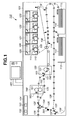
- Fig. 1 is a sectional view illustrating a structure of an image forming apparatus 100.
- the image forming apparatus 100 includes a housing 101.
- the housing 101 includes mechanisms for constituting an engine unit, and a control board storage unit 104.
- the control board storage unit 104 stores an engine control unit 102 and a printer controller 103.
- the engine control unit 102 controls each printing processing (such as paper feeding processing) performed by each of the mechanisms.
- the engine unit includes four stations 120, 121, 122, and 123 corresponding to yellow (Y), magenta (M), cyan (C), and black (K).
- the stations 120, 121, 122, and 123 are image forming units that transfer toner to a sheet 110 to form an image.
- the stations 120, 121, 122, and 123 mostly include common parts.
- Photosensitive drums 105 are a kind of image bearing member.
- Primary charging devices 111 charge the surfaces of the photosensitive drums 105 with a uniform potential.
- Lasers 108 output laser light, which forms latent images on the photosensitive drums 105.
- Developing devices 112 develop the latent images into toner images by using color materials (toner).
- the toner images (visible images) are transferred to an intermediate transfer member 106.
- a transfer roller 114 transfers the visible images formed on the intermediate transfer member 106 to a sheet 110 conveyed from a storage unit 113.
- a fixing processing mechanism includes a first fixing device 150 and a second fixing device 160.
- the first and second fixing devices 150 and 160 apply heat and pressure to the toner images transferred to the sheet 110 and thereby fix the toner images to the sheet 110.
- the first fixing device 150 includes a fixing roller 151 for applying heat to the sheet 110, a pressure belt 152 for pressing the sheet 110 against the fixing roller 151, and a first fixing sensor 153 that detects completion of fixing.
- the fixing roller 151 is a hollow roller with a heater inside.
- the second fixing device 160 is arranged downstream of the first fixing device 150 in a conveyance direction of the sheet 110.
- the second fixing device 160 adds a gloss to the toner images on the sheet 110 and/or secures fixability.
- the second fixing device 160 includes a fixing roller 161, a pressure roller 162, and a second fixing sensor 163.
- Some types of sheets 110 need not pass through the second fixing device 160. Such sheets 110 pass through a conveyance path 130 instead of the second fixing device 160 for the purpose of reducing energy consumption.
- the sheet 110 passing through the first fixing unit 150 is conveyed to the second fixing device 160.
- the sheet 110 is conveyed through the conveyance path 130 to bypass the second fixing device 160.
- Whether to convey the sheet 110 to the second fixing device 160 or convey the sheet 110 to bypass the second fixing device 160 is controlled by a changeover member 131.
- a changeover member 132 is a guide member that guides the sheet 110 to a conveyance path 135 or an external discharge path 139.
- a leading edge of the sheet 110 guided into the conveyance path 135 passes a reversing sensor 137 and is conveyed to a reversing unit 136.
- the reversing sensor 137 detects a trailing edge of the sheet 110, the conveyance direction of the sheet 110 is switched.
- a changeover member 133 is a guide member that guides the sheet 110 to a conveyance path 138 for two-sided image formation or the conveyance path 135.
- Color sensors 200 for measuring measurement images (hereinafter, referred to as patch images) formed on the sheet 110 are arranged on the conveyance path 135.
- the color sensors 200 include four color sensors 200a, 200b, 200c, and 200d juxtaposed in a direction orthogonal to the conveyance direction of the sheet 110, and can measure four rows of patch images.
- the engine control unit 102 performs density adjustment, gradation adjustment, and multi-color correction processing.
- the color sensors 200 measure the density of monochrome measurement images.
- the color sensors 200 measure the color of measurement images formed by superposing a plurality of colors.
- a changeover member 134 is a guide member that guides the sheet 110 to the external discharge path 139.
- the sheet 110 conveyed through the discharge path 139 is discharged outside the image forming apparatus 100.
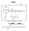
- Fig. 2 is a diagram illustrating the structure of a sensor 200.
- the color sensor 200 includes a white light-emitting diode (LED) 201, a diffraction grating 202, a line sensor 203, a calculation unit 204, and a memory 205.
- the white LED 201 is a light emitting element which irradiates a patch image 220 on the sheet 110 with light. The light reflected from the patch image 220 passes through a window 206 made of a transparent member.
- the diffraction grating 202 disperses the light reflected from the patch image 220, which is a measurement object, by wavelength.
- the line sensor 203 is a light detection element including N number of light-receiving elements that detect the light resolved by the diffraction grating 202 by wavelength.
- the calculation unit 204 performs various calculations based on the light intensity values of respective pixels detected by the line sensor 203.
- the memory 205 stores various types of data to be used by the calculation unit 204.
- the calculation unit 204 includes a spectral calculation unit that calculates spectral reflectances from the light intensity values.
- the color sensor 200 may further include a lens that condenses the light emitted from the white LED 201 on the patch image 220 formed on the sheet 110 and/or condenses the light reflected from the patch image 220 on the diffraction grating 202.
- White reference plates 230 are arranged in positions opposed to the color sensors 200.
- the color sensors 200 measure light reflected from the white reference plates 230 to perform white correction to be described below.
- the image forming apparatus 100 For the multi-color correction processing, the image forming apparatus 100 generates an International Color Consortium (ICC) profile, which will be described below, from the detection results of the patch images 220 including multiple colors. Using the ICC profile, the image forming apparatus 100 converts an input image into an output image.
- ICC International Color Consortium
- the patch images 220 including multiple colors are formed by changing a halftone dot area ratio of each of the four colors, C, M, Y, and K, in three levels (0%, 50%, and 100%) so that the patch images 220 cover all combinations of respective halftone dot area ratios of the four colors.
- the patch images 220 formed on the sheet 110 include four rows of the patch images 220a, 200b, 200c, and 220d which are arranged to be read by the color sensors 200a, 200b, 200c, and 200d, respectively.
- the patch images 220a, 200b, 200c, and 220d include first patch images (220a-1, 220b-1, 220c-1, and 220d-1) to M-th patch images (220a-M, 220b-M, 220c-M, and 220d-M).
- the present exemplary embodiment uses an ICC profile which has recently been accepted in the market as a profile implementing excellent color reproducibility.
- the application of an exemplary embodiment of the present invention is not limited to an ICC profile.
- An exemplary embodiment of the present invention may be applied to the color rendering dictionary (CRD) which has been employed for PostScript Level 2 and later proposed by Adobe Systems Incorporated, and a color separation table in Photoshop (registered trademark).
- CCD color rendering dictionary
- the user may operate the operation unit 180 to give an instruction to generate a color profile in various situations, for example, when a customer engineer replaces a part, before a job that requires high color matching accuracy is performed, or when the user wants to know the color of a final output product in the design planning phase.
- Fig. 4 is a block diagram illustrating the printer controller 103 which performs profile generation processing.
- the printer controller 103 includes a central processing unit (CPU).
- the printer control 103 reads a program for performing a flowchart to be described below from a storage unit 350, and executes the program.
- Fig. 4 illustrates the interior of the printer controller 103 in blocks.
- a profile generation unit 301 When the operation unit 180 receives a profile generation instruction, a profile generation unit 301 outputs a CMYK color chart, which is an International Organization for Standardization (ISO) 12642 test form, to the engine control unit 102 without a profile.
- the profile generation unit 301 sends a measurement instruction to a color sensor control unit 302.
- the engine control unit 102 controls the image forming apparatus 100 to perform processes such as charging, exposure, development, transfer, and fixing. As a result, an ISO 12642 test form is formed on a sheet 110.
- the color sensor control unit 302 controls the color sensors 200 to measure the ISO 12642 test form.
- the color sensors 200 output the measurement result, which is spectral reflectance data, to a Lab calculation unit 303 of the printer controller 103.
- the Lab calculation unit 303 converts the spectral reflectance data into color value data (L*a*b* data) and outputs the L*a*b* data to the profile generation unit 301.
- the L*a*b* data output from the Lab calculation unit 303 is converted by using a color sensor input ICC profile stored in a color sensor input ICC profile storage unit 304.
- the Lab calculation unit 303 may convert the spectral reflectance data into the International Commission on Illumination (CIE) 1931 XYZ color space which uses a device-independent color space signal.
- CIE International Commission on Illumination
- the profile generation unit 301 generates an output ICC profile from a relationship between the CMYK color signals output to the engine generation unit 102 and the L*a*b* data converted by using the color sensor input ICC profile.
- the profile generation unit 301 stores the generated output ICC profile in an output ICC profile storage unit 305.
- the ISO 12642 test form includes patches of CMYK color signals that cover the entire color reproduction range a typical copying machine can output.
- the profile generation unit 301 generates a color conversion table from a relationship between the respective color signal values and the measured L*a*b* values. In other words, the profile generation unit 301 generates a CMYK-to-Lab conversion table. Based on the conversion table, the profile generation unit 301 generates an inverse conversion table.
- the profile generation unit 301 When receiving a profile generation command from a host computer via an interface (I/F) 308, the profile generation unit 301 outputs the generated output ICC profile to the host computer via the I/F 308.
- the host computer can perform color conversion corresponding to the ICC profile in an application program or programs.
- the image forming apparatus 100 includes shutters 214 that block light emitted from the color sensors 200.
- a shutter drive motor 311 is a motor for driving the shutters 214.
- the engine control unit 102 controls the shutter drive motor 311.
- the input ICC profile storage unit 307 performs RGB-to-L*a*b* or CMYK-to-L*a*b* conversion according to the image signal input from the I/F 308.
- the input ICC profile storage unit 307 stores an input ICC profile which includes a plurality of lookup tables (LUTs).
- Examples of the LUTs include a one-dimensional LUT for controlling a gamma value of the input signal, a multi-color LUT called direct mapping, and a one-dimensional LUT for controlling the gamma value of generated conversion data.
- the input ICC profile storage unit 307 converts the input image signal from the device-dependent color space to device-independent L*a*b* data.
- the image signal converted into L*a*b* coordinates is input to a color management module (CMM) 306.
- the CMM 306 performs various color conversions. For example, the CMM 306 performs a gamut conversion to map mismatches between the reading color space of the scanner unit serving as an input device and the output color reproduction range of the image forming apparatus 100 serving as an output device.
- the CMM 306 also performs color conversion to adjust a mismatch between the type of the light source at the time of input and the type of the light source with which the output product is observed (also referred to as a mismatch of color temperature settings).
- the CMM 306 converts the L*a*b* data into L'*a'*b'* data, and outputs the L'*a'*b'* data to the output ICC profile storage unit 305.
- the output ICC profile storage unit 305 contains the output ICC profile generated by measurement.
- the output ICC profile storage unit 305 performs color conversion on the L'*a'*b'* data by using the new output ICC profile generated.
- the output ICC profile storage unit 305 thereby converts the L'*a'*b'* data into CMYK signals dependent on the output device, and outputs the CMYK signals to the engine control unit 102.
- the CMM 306 is separated from the input ICC profile storage unit 307 and the output ICC profile storage unit 305.
- the CMM 306 refers to a module that governs color management.
- the module performs color conversion by using an input profile (printing ICC profile 501) and an output profile (printer ICC profile 502).
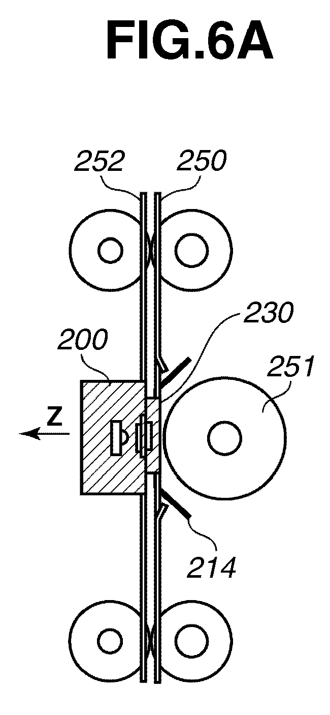
- Figs. 6A and 6B are diagrams illustrating the operation of the color sensors 200 measuring the white reference plates 230.
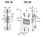
- Fig. 7A and 7B are diagrams illustrating the operation of the color sensors 200 measuring the patch images 220 on the sheet 110.
- Fig. 6A is a sectional view of the vicinity of the color sensors 200.
- Fig. 6B is a perspective view three-dimensionally illustrating a state near the white reference plates 230.
- the Z-axis of Fig. 6A and the Z-axis of Fig. 6B indicate the same direction.
- Figs. 7A and 7B have a similar layout to that of Figs. 6A and 6B .
- the shutters 214 are open and the white reference plates 230 are located close to the color sensors 200.
- the white reference plates 230 are pressed against a conveyance guide 252 by a pressure member such as a spring, and thereby positioned with respect to the color sensors 200.
- a pressure member such as a spring
- the white reference plates 230 are configured to be pressed against the conveyance guide 252 in view of the durability of the color sensors 200. Instead, in view of the measurement accuracy, the white reference plates 230 may be pressed against the color sensors 200 for positioning.
- the color sensors 200 measure the white reference plates 230.
- the white reference plates 230 are positioned to where the sheet 110 passes.
- the shutters 214 are shifted in a positive X direction and retracted off the white reference plates 230.
- the retracted positions of the shutters 214 are between the conveyance rollers 251 separated from the conveyance guide 252 and the conveyance guide 252.
- the four color sensors 200a, 200b, 200c, and 200d are juxtaposed in the direction orthogonal to the conveyance direction of the sheet 110.
- the shutters 214a, 214b, 214c, and 214d, the white reference plates 230a, 230b, 230c, and 230d, and the conveyance rollers 251a, 251b, 251c, and 251d are arranged in positions opposed to the color sensors 200a, 200b, 200c, and 200d, respectively.
- the white reference plates 230 are separated from the color sensors 200 not to interfere with the conveyance of the sheet 110.
- the shutters 214 move to shielding positions between the white reference plates 230 and the color sensors 200. In the shielding positions, the shutters 214 are located approximately on the same plane as that of a conveyance guide 250 not to interfere with the conveyance of the sheet 110.
- the shutters 214 can cover the white reference plates 230 so that foreign substances such as paper dust are prevented from adhering to the white reference plates 230 during the print operation.
- the sheet 110 is conveyed between the conveyance guides 250 and 252.
- the white LEDs 201 of the color sensors 200 are turned off.
- Fig. 8A illustrates a state during measurement of the patch images 220.
- the conveyance rollers 251 are moved in a direction toward the color sensors 200 (Z direction), so that the sheet 110 is pressed toward the color sensors 200 while being conveyed.
- the reason is that the position of the sheet 110 needs to be adjusted to the focus positions of the color sensors 200.
- the focus positions are set to the positions along the conveyance guide 252.
- the color sensors 200 measure the patch images 220 on the conveyed sheet 110.
- the white reference plates 230 are separated from the color sensors 200 not to interfere with the conveyance of the sheet 110.
- the shutters 214 are located between the white reference plates 230 and the color sensors 200. The purpose is to prevent the white reference plates 230 from being discolored by the irradiation of light transmitted through the sheet 110 on which the patch images 220 are formed. Another purpose is to prevent foreign substances such as paper dust from adhering to the white reference plates 230.
- Fig. 9 is a diagram illustrating a configuration of a shutter drive unit 260.
- the X-, Y-, and Z-axes of Fig. 9 correspond to the X-, Y-, and Z-axes of Figs. 6A, 6B , 7A, 7B , 8A, and 8B .
- the shutter drive unit 260 is fixed to the conveyance guide 250 which is fixed to a frame (not illustrated).
- the shutter drive motor 311 drives a slide drive member 261 to reciprocate in the X direction.
- the slide drive member 261 is connected to the shutters 214 via support portions 262 to be described below, thereby constituting a mechanically interlockable configuration.
- the shutters 214 are supported to be movable in the X direction.
- White reference plate holding members 266 come into contact with slide cams which are integrally formed with the shutters 214. By such a configuration, the white reference plates 230 and the shutter 214 are simultaneously pressed in the Z direction for positioning.
- the white reference plates 230, the shutters 214, and the conveyance rollers 251 take different positions depending on the operation of the image forming apparatus 100 (white correction, a print operation, and the measurement of the patch images 220).
- the positions will be described in detail with reference to Figs. 10A, 10B, 10C , and 11 .
- the X- and Z-axes of Figs. 10A, 10B, and 10C correspond to the X- and Z-axes of Figs. 6A, 6B , 7A, 7B , 8A, 8B , and 9 .
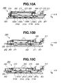
- Fig. 10A is a diagram illustrating a white correction position.
- Fig. 11 the white correction position is illustrated on the rightmost side.
- the white correction needs to be performed by using the white reference plates 230 before the measurement.
- the white reference plates 230 need to be positioned to the focus positions of the color sensors 200.
- the shutters 214 are moved to open positions which expose the white reference plates 230.
- the shutter drive motor 311 moves the slide drive member 261 in the positive X direction
- the shutters 214 can be moved in the positive X direction in an interlocked manner.
- a roller support member 268 comes into contact with cam portions 270 of the slide drive member 261, whereby the conveyance rollers 251 are positioned to the positions separated from the color sensors 200.
- Fig. 10B is a diagram illustrating a print position.
- the print position is illustrated between the white correction position and a patch image measurement position.
- the shutters 214 need to protect the white reference plates 230 from the adhesion of paper dust of sheets 110 conveyed in large numbers and impurities evaporating from thermally fixed toner.
- the roller support member 268 comes into contact with cam portions 271 of the slide drive member 261, whereby the conveyance rollers 251 are set to approximately the same position as a sheet passing surface of the conveyance guide 250.
- the shutters 214 move to closed positions where the shutters 214 cover the white reference plates 230.
- the shutters 214 are pulled in a negative X direction in the diagram by shutter tension springs 265 and come into contact with shafts 267 illustrated in Fig. 9 to stop.
- the shutters 214 are stopped at the positions along the surface of the conveyance guide 250.
- Fig. 10C is a diagram illustrating the patch image measurement position.
- the patch image measurement position is illustrated on the leftmost side.
- the image forming apparatus 100 conveys and measures a sheet 110 on which the patch images 220 are formed, the sheet 110 needs to be positioned to the focus positions of the color sensors 200.
- the roller support member 268 comes into contact with cam portions 272 of the slide drive member 261, whereby the conveyance rollers 251 are pressed toward the conveyance guide 252 and positioned to the focus positions with high accuracy.
- the slide drive member 261 is unlinked from the shutters 214. Consequently, while the slide drive member 261 moves from the position illustrated in Fig. 10B to the position illustrated in Fig. 10C , the shutters 214 remain in the closed positions and only the conveyance rollers 251 can be operated.
- Fig. 12 is a flowchart illustrating a drive control of the shutters 214 during white correction and patch image measurement. This flowchart is executed by the printer controller 103. The printer controller 103 performs the processing of the flowchart in response to an instruction to execute the multi-color correction processing from the operation unit 180.
- step S1201 the printer controller 103 instructs the engine control unit 102 to open the shutters 214 to expose the white reference plates 230 and move the white reference plates 230 to the focus positions of the color sensors 200 in an interlocked manner.
- the engine control unit 102 controls the shutter drive motor 311 based on the instruction.
- step S1202 the printer controller 103 irradiates the write reference plates 230 with light and measures light reflected from the white reference plates 230 by using the color sensors 200.
- the printer controller 103 thereby obtains measurement values W( ⁇ ).
- step S1203 after the end of the measurement of the white reference plates 230, the printer controller 103 instructs the engine control unit 102 to separate the white reference plates 230 from the color sensors 200 and close the shutters 214 to cover the white reference plates 230 in an interlocked manner.
- the engine control unit 102 controls the shutter drive motor 311 based on the instruction.
- step S1204 the printer controller 103 instructs the engine control unit 102 to feed a sheet 110 from the storage unit 113.
- step S1205 the printer controller 103 instructs the engine control unit 102 to form the patch images 220 for the multi-color correction processing on the fed sheet 110.
- step S1206 the printer controller 103 waits until the sheet 110 on which the patch images 220 are formed reaches the color sensors 200. If the sheet 110 has reached the color sensors 200 (YES in step S1206), then in step S1207, the printer controller 103 causes the color sensors 200 to measure the patch images 220. The printer controller 103 thereby obtains measurement values P( ⁇ ).
- the printer controller 103 then calculates color value data (L*a*b*) from the spectral reflectance data R( ⁇ ) output from the color sensors 200 by using the Lab calculation unit 303.
- the printer controller 103 generates an ICC profile as an image forming condition by the foregoing processing based on the color value data (L*a*b*).
- the printer controller 103 stores the ICC profile in the output ICC profile control unit 305.
- step S1211 the printer controller 103 instructs the engine control unit 102 to discharge the sheet 110, and ends the processing of the flowchart.
- the shutters 214 are opened and the white reference pates 230 are moved to the focus positions to enable accurate white correction.
- the white reference plates 230 are covered with the shutters 214 during the measurement of the patch images 220. This can suppress the discoloration of the white reference plates 230 due to light transmitted through the sheet 110.
- the white reference plates 230 are covered with the shutters 214 when the white reference plates 230 are not used. This can prevent foreign substances such as paper dust from adhering to the white reference plates 230.
Landscapes
- Engineering & Computer Science (AREA)
- Physics & Mathematics (AREA)
- General Physics & Mathematics (AREA)
- Signal Processing (AREA)
- Multimedia (AREA)
- Spectroscopy & Molecular Physics (AREA)
- Health & Medical Sciences (AREA)
- Biomedical Technology (AREA)
- General Health & Medical Sciences (AREA)
- Microelectronics & Electronic Packaging (AREA)
- Control Or Security For Electrophotography (AREA)
- Facsimile Image Signal Circuits (AREA)
- Color Electrophotography (AREA)
- Facsimile Scanning Arrangements (AREA)
- Color Image Communication Systems (AREA)
Abstract
Description
- The present invention relates to an image forming apparatus which has a function of measuring color of a measurement image.
- An image forming apparatus has image qualities such as granularity, in-plane uniformity, character quality, and color reproducibility (including color stability). With the proliferation of multi-color image forming apparatuses these days, the color reproducibility is sometimes said to be the most important image quality.
- People remember empirically expected colors (of human skin, blue sky, and metal in particular), and will feel uncomfortable if acceptable ranges thereof are exceeded. Such colors are called memory colors. Ensuring the reproducibility of memory colors has been often required when outputting photographs.
- Aside from photographic images, office users may feel unconformable about a color difference between document images displayed on a monitor and output documents. Graphic arts users are also pursuing the color reproducibility of computer graphics (CG) images. The demand for the color reproducibility (including stability) of an image forming apparatus is therefore increasing.
- To satisfy the users' demand for the color reproducibility, Japanese Patent Application Laid-Open No.
2004-086013 - However, the color sensor discussed in Japanese Patent Application Laid-Open No.
2004-086013 - However, during measurement of the patch image, if the white reference plate is arranged in the position opposed to the color sensor, the white reference plate is irradiated with light transmitted through the sheet on which the patch image is formed, and thereby discolored. The reason is that the white reference plate contains a substance that discolors due to a photo-oxidation effect.
- Thus, there has been a problem that as the number of times of irradiation of the white reference plate with light increases, the discoloration of the white reference plate caused by the irradiating light gradually advances, leading a gradual increase in errors in measurement values.
- Another problem is that when a sheet passes through a conveyance path between the color sensor and the white reference plate, foreign substances such as paper dust can adhere to the surface of the white reference plate, causing an error in the measurement value of the white reference plate by the color sensor.
- The present invention is directed to an image forming apparatus capable of suppressing discoloration of a white reference plate and preventing foreign substances such as paper dust from adhering to the white reference plate.
- According to an aspect of the present invention, there is provided an image forming apparatus as specified in
claims 1 to 11. - Further features of the present invention will become apparent from the following description of exemplary embodiments with reference to the attached drawings.
-
-
Fig. 1 a sectional view illustrating a structure of an image forming apparatus. -
Fig. 2 is a diagram illustrating a structure of a color sensor. -
Fig. 3 is an image diagram illustrating a color measurement chart. -
Fig. 4 is a block diagram illustrating a system configuration of the image forming apparatus. -
Fig. 5 is a schematic diagram illustrating a color management environment. -
Figs. 6A and 6B are diagrams illustrating a state during measurement of white reference plates. -
Figs. 7A and 7B are diagrams illustrating a state in a print operation. -
Figs. 8A and 8B are diagrams illustrating a state during measurement of patch images. -
Fig. 9 is a diagram illustrating a configuration of a shutter drive unit. -
Figs. 10A, 10B, and 10C are diagrams illustrating three positions in detail. -
Fig. 11 is a diagram illustrating operations of shutters, the white reference plates, and conveyance rollers when a slide drive member is moved. -
Fig. 12 is a flowchart illustrating a shutter drive control during white correction and patch image measurement. - An exemplary embodiment of the present invention will be described below by using an electrophotographic laser beam printer. In the following description, the electrophotographic method is employed as an example of the image forming method. However, an exemplary embodiment of the present invention may also be applied to an inkjet method and a sublimation method. The inkjet method uses an image forming unit that discharges ink to form an image on a sheet, and a fixing unit (drying unit) that dries the ink.
-
Fig. 1 is a sectional view illustrating a structure of animage forming apparatus 100. Theimage forming apparatus 100 includes ahousing 101. Thehousing 101 includes mechanisms for constituting an engine unit, and a controlboard storage unit 104. The controlboard storage unit 104 stores anengine control unit 102 and aprinter controller 103. Theengine control unit 102 controls each printing processing (such as paper feeding processing) performed by each of the mechanisms. - As illustrated in
Fig. 1 , the engine unit includes fourstations stations sheet 110 to form an image. Thestations Photosensitive drums 105 are a kind of image bearing member.Primary charging devices 111 charge the surfaces of thephotosensitive drums 105 with a uniform potential.Lasers 108 output laser light, which forms latent images on thephotosensitive drums 105. Developingdevices 112 develop the latent images into toner images by using color materials (toner). The toner images (visible images) are transferred to anintermediate transfer member 106. Atransfer roller 114 transfers the visible images formed on theintermediate transfer member 106 to asheet 110 conveyed from astorage unit 113. - A fixing processing mechanism according to the present exemplary embodiment includes a
first fixing device 150 and asecond fixing device 160. The first andsecond fixing devices sheet 110 and thereby fix the toner images to thesheet 110. Thefirst fixing device 150 includes afixing roller 151 for applying heat to thesheet 110, apressure belt 152 for pressing thesheet 110 against thefixing roller 151, and afirst fixing sensor 153 that detects completion of fixing. Thefixing roller 151 is a hollow roller with a heater inside. - The
second fixing device 160 is arranged downstream of thefirst fixing device 150 in a conveyance direction of thesheet 110. Thesecond fixing device 160 adds a gloss to the toner images on thesheet 110 and/or secures fixability. Like thefirst fixing device 150, thesecond fixing device 160 includes a fixingroller 161, apressure roller 162, and asecond fixing sensor 163. Some types ofsheets 110 need not pass through thesecond fixing device 160.Such sheets 110 pass through aconveyance path 130 instead of thesecond fixing device 160 for the purpose of reducing energy consumption. - For example, if a setting is made to give a high gloss to a
sheet 110 or if, like thick paper, asheet 110 needs a great amount of heat for fixing, thesheet 110 passing through thefirst fixing unit 150 is conveyed to thesecond fixing device 160. On the other hand, if asheet 110 is plain paper or thin paper and no setting is made to give a high gloss, thesheet 110 is conveyed through theconveyance path 130 to bypass thesecond fixing device 160. Whether to convey thesheet 110 to thesecond fixing device 160 or convey thesheet 110 to bypass thesecond fixing device 160 is controlled by achangeover member 131. - A
changeover member 132 is a guide member that guides thesheet 110 to aconveyance path 135 or anexternal discharge path 139. A leading edge of thesheet 110 guided into theconveyance path 135 passes a reversingsensor 137 and is conveyed to a reversingunit 136. When the reversingsensor 137 detects a trailing edge of thesheet 110, the conveyance direction of thesheet 110 is switched. Achangeover member 133 is a guide member that guides thesheet 110 to aconveyance path 138 for two-sided image formation or theconveyance path 135. -
Color sensors 200 for measuring measurement images (hereinafter, referred to as patch images) formed on thesheet 110 are arranged on theconveyance path 135. Thecolor sensors 200 include fourcolor sensors sheet 110, and can measure four rows of patch images. When an instruction for color measurement is given from anoperation unit 180, theengine control unit 102 performs density adjustment, gradation adjustment, and multi-color correction processing. In the density adjustment and gradation adjustment, thecolor sensors 200 measure the density of monochrome measurement images. In the multi-color correction processing, thecolor sensors 200 measure the color of measurement images formed by superposing a plurality of colors. - A
changeover member 134 is a guide member that guides thesheet 110 to theexternal discharge path 139. Thesheet 110 conveyed through thedischarge path 139 is discharged outside theimage forming apparatus 100. -
Fig. 2 is a diagram illustrating the structure of asensor 200. Thecolor sensor 200 includes a white light-emitting diode (LED) 201, adiffraction grating 202, aline sensor 203, acalculation unit 204, and amemory 205. Thewhite LED 201 is a light emitting element which irradiates apatch image 220 on thesheet 110 with light. The light reflected from thepatch image 220 passes through awindow 206 made of a transparent member. - The
diffraction grating 202 disperses the light reflected from thepatch image 220, which is a measurement object, by wavelength. Theline sensor 203 is a light detection element including N number of light-receiving elements that detect the light resolved by thediffraction grating 202 by wavelength. Thecalculation unit 204 performs various calculations based on the light intensity values of respective pixels detected by theline sensor 203. - The
memory 205 stores various types of data to be used by thecalculation unit 204. Thecalculation unit 204, for example, includes a spectral calculation unit that calculates spectral reflectances from the light intensity values. Thecolor sensor 200 may further include a lens that condenses the light emitted from thewhite LED 201 on thepatch image 220 formed on thesheet 110 and/or condenses the light reflected from thepatch image 220 on thediffraction grating 202. -
White reference plates 230 are arranged in positions opposed to thecolor sensors 200. In the present exemplary embodiment, thecolor sensors 200 measure light reflected from thewhite reference plates 230 to perform white correction to be described below. - For the multi-color correction processing, the
image forming apparatus 100 generates an International Color Consortium (ICC) profile, which will be described below, from the detection results of thepatch images 220 including multiple colors. Using the ICC profile, theimage forming apparatus 100 converts an input image into an output image. - The
patch images 220 including multiple colors are formed by changing a halftone dot area ratio of each of the four colors, C, M, Y, and K, in three levels (0%, 50%, and 100%) so that thepatch images 220 cover all combinations of respective halftone dot area ratios of the four colors. As illustrated inFig. 3 , thepatch images 220 formed on thesheet 110 include four rows of thepatch images color sensors patch images - The present exemplary embodiment uses an ICC profile which has recently been accepted in the market as a profile implementing excellent color reproducibility. However, the application of an exemplary embodiment of the present invention is not limited to an ICC profile. An exemplary embodiment of the present invention may be applied to the color rendering dictionary (CRD) which has been employed for
PostScript Level 2 and later proposed by Adobe Systems Incorporated, and a color separation table in Photoshop (registered trademark). - The user may operate the
operation unit 180 to give an instruction to generate a color profile in various situations, for example, when a customer engineer replaces a part, before a job that requires high color matching accuracy is performed, or when the user wants to know the color of a final output product in the design planning phase. -
Fig. 4 is a block diagram illustrating theprinter controller 103 which performs profile generation processing. Theprinter controller 103 includes a central processing unit (CPU). Theprinter control 103 reads a program for performing a flowchart to be described below from astorage unit 350, and executes the program. To facilitate understanding of the processing performed by theprinter controller 103,Fig. 4 illustrates the interior of theprinter controller 103 in blocks. - When the
operation unit 180 receives a profile generation instruction, aprofile generation unit 301 outputs a CMYK color chart, which is an International Organization for Standardization (ISO) 12642 test form, to theengine control unit 102 without a profile. Theprofile generation unit 301 sends a measurement instruction to a colorsensor control unit 302. Theengine control unit 102 controls theimage forming apparatus 100 to perform processes such as charging, exposure, development, transfer, and fixing. As a result, an ISO 12642 test form is formed on asheet 110. - The color
sensor control unit 302 controls thecolor sensors 200 to measure the ISO 12642 test form. Thecolor sensors 200 output the measurement result, which is spectral reflectance data, to aLab calculation unit 303 of theprinter controller 103. TheLab calculation unit 303 converts the spectral reflectance data into color value data (L*a*b* data) and outputs the L*a*b* data to theprofile generation unit 301. Here, the L*a*b* data output from theLab calculation unit 303 is converted by using a color sensor input ICC profile stored in a color sensor input ICCprofile storage unit 304. TheLab calculation unit 303 may convert the spectral reflectance data into the International Commission on Illumination (CIE) 1931 XYZ color space which uses a device-independent color space signal. - The
profile generation unit 301 generates an output ICC profile from a relationship between the CMYK color signals output to theengine generation unit 102 and the L*a*b* data converted by using the color sensor input ICC profile. Theprofile generation unit 301 stores the generated output ICC profile in an output ICCprofile storage unit 305. - The ISO 12642 test form includes patches of CMYK color signals that cover the entire color reproduction range a typical copying machine can output. The
profile generation unit 301 generates a color conversion table from a relationship between the respective color signal values and the measured L*a*b* values. In other words, theprofile generation unit 301 generates a CMYK-to-Lab conversion table. Based on the conversion table, theprofile generation unit 301 generates an inverse conversion table. - When receiving a profile generation command from a host computer via an interface (I/F) 308, the
profile generation unit 301 outputs the generated output ICC profile to the host computer via the I/F 308. The host computer can perform color conversion corresponding to the ICC profile in an application program or programs. - As will be described in detail below, the
image forming apparatus 100 includesshutters 214 that block light emitted from thecolor sensors 200. Ashutter drive motor 311 is a motor for driving theshutters 214. Theengine control unit 102 controls theshutter drive motor 311. - Color conversion for normal color output will be described. Red, green, and blue (RGB) signal values that are input from a scanner unit via the I/
F 308 or an image signal that is input assuming Japan Color or other standard printing CMYK signal values is/are transmitted to an input ICCprofile storage unit 307 intended for external input. The input ICCprofile storage unit 307 performs RGB-to-L*a*b* or CMYK-to-L*a*b* conversion according to the image signal input from the I/F 308. The input ICCprofile storage unit 307 stores an input ICC profile which includes a plurality of lookup tables (LUTs). - Examples of the LUTs include a one-dimensional LUT for controlling a gamma value of the input signal, a multi-color LUT called direct mapping, and a one-dimensional LUT for controlling the gamma value of generated conversion data. Using such LUTs, the input ICC
profile storage unit 307 converts the input image signal from the device-dependent color space to device-independent L*a*b* data. - The image signal converted into L*a*b* coordinates is input to a color management module (CMM) 306. The
CMM 306 performs various color conversions. For example, theCMM 306 performs a gamut conversion to map mismatches between the reading color space of the scanner unit serving as an input device and the output color reproduction range of theimage forming apparatus 100 serving as an output device. TheCMM 306 also performs color conversion to adjust a mismatch between the type of the light source at the time of input and the type of the light source with which the output product is observed (also referred to as a mismatch of color temperature settings). - In such a manner, the
CMM 306 converts the L*a*b* data into L'*a'*b'* data, and outputs the L'*a'*b'* data to the output ICCprofile storage unit 305. The output ICCprofile storage unit 305 contains the output ICC profile generated by measurement. The output ICCprofile storage unit 305 performs color conversion on the L'*a'*b'* data by using the new output ICC profile generated. The output ICCprofile storage unit 305 thereby converts the L'*a'*b'* data into CMYK signals dependent on the output device, and outputs the CMYK signals to theengine control unit 102. - In
Fig. 4 , theCMM 306 is separated from the input ICCprofile storage unit 307 and the output ICCprofile storage unit 305. In fact, as illustrated inFig. 5 , theCMM 306 refers to a module that governs color management. The module performs color conversion by using an input profile (printing ICC profile 501) and an output profile (printer ICC profile 502). - Now, an operation of the
white reference plates 230 and theshutters 214 will be described with reference toFigs. 6A, 6B ,7A, 7B ,8A, 8B , and9 .Figs. 6A and 6B are diagrams illustrating the operation of thecolor sensors 200 measuring thewhite reference plates 230.Fig. 7A and 7B are diagrams illustrating the operation of thecolor sensors 200 measuring thepatch images 220 on thesheet 110. -
Fig. 6A is a sectional view of the vicinity of thecolor sensors 200.Fig. 6B is a perspective view three-dimensionally illustrating a state near thewhite reference plates 230. The Z-axis ofFig. 6A and the Z-axis ofFig. 6B indicate the same direction.Figs. 7A and 7B have a similar layout to that ofFigs. 6A and 6B . - As illustrated in
Fig. 6A , during measurement of thewhite reference plates 230, theshutters 214 are open and thewhite reference plates 230 are located close to thecolor sensors 200. Thewhite reference plates 230 are pressed against aconveyance guide 252 by a pressure member such as a spring, and thereby positioned with respect to thecolor sensors 200. By such a configuration, the positions of thewhite reference plates 230 with respect to thecolor sensors 200 are prevented from varying in angle or distance. - The
white reference plates 230 are configured to be pressed against theconveyance guide 252 in view of the durability of thecolor sensors 200. Instead, in view of the measurement accuracy, thewhite reference plates 230 may be pressed against thecolor sensors 200 for positioning. - With the
white reference plates 230 thus pressed and positioned, thecolor sensors 200 measure thewhite reference plates 230. In such a state (contact state), thewhite reference plates 230 are positioned to where thesheet 110 passes. - As illustrated in
Fig. 6B , during the measurement (white correction) of thewhile reference plates 230, theshutters 214 are shifted in a positive X direction and retracted off thewhite reference plates 230. The retracted positions of theshutters 214 are between theconveyance rollers 251 separated from theconveyance guide 252 and theconveyance guide 252. - As described above, the four
color sensors sheet 110. Theshutters white reference plates conveyance rollers color sensors - In a print operation, as illustrated in
Fig. 7A , thewhite reference plates 230 are separated from thecolor sensors 200 not to interfere with the conveyance of thesheet 110. Theshutters 214 move to shielding positions between thewhite reference plates 230 and thecolor sensors 200. In the shielding positions, theshutters 214 are located approximately on the same plane as that of aconveyance guide 250 not to interfere with the conveyance of thesheet 110. As illustrated inFig. 7B , theshutters 214 can cover thewhite reference plates 230 so that foreign substances such as paper dust are prevented from adhering to thewhite reference plates 230 during the print operation. - In the print operation, the
sheet 110 is conveyed between the conveyance guides 250 and 252. Thewhite LEDs 201 of thecolor sensors 200 are turned off. -
Fig. 8A illustrates a state during measurement of thepatch images 220. Theconveyance rollers 251 are moved in a direction toward the color sensors 200 (Z direction), so that thesheet 110 is pressed toward thecolor sensors 200 while being conveyed. The reason is that the position of thesheet 110 needs to be adjusted to the focus positions of thecolor sensors 200. The focus positions are set to the positions along theconveyance guide 252. Thecolor sensors 200 measure thepatch images 220 on the conveyedsheet 110. - The
white reference plates 230 are separated from thecolor sensors 200 not to interfere with the conveyance of thesheet 110. Theshutters 214 are located between thewhite reference plates 230 and thecolor sensors 200. The purpose is to prevent thewhite reference plates 230 from being discolored by the irradiation of light transmitted through thesheet 110 on which thepatch images 220 are formed. Another purpose is to prevent foreign substances such as paper dust from adhering to thewhite reference plates 230. -
Fig. 9 is a diagram illustrating a configuration of ashutter drive unit 260. The X-, Y-, and Z-axes ofFig. 9 correspond to the X-, Y-, and Z-axes ofFigs. 6A, 6B ,7A, 7B ,8A, and 8B . - The
shutter drive unit 260 is fixed to theconveyance guide 250 which is fixed to a frame (not illustrated). Theshutter drive motor 311 drives aslide drive member 261 to reciprocate in the X direction. Theslide drive member 261 is connected to theshutters 214 viasupport portions 262 to be described below, thereby constituting a mechanically interlockable configuration. - The
shutters 214 are supported to be movable in the X direction. White referenceplate holding members 266 come into contact with slide cams which are integrally formed with theshutters 214. By such a configuration, thewhite reference plates 230 and theshutter 214 are simultaneously pressed in the Z direction for positioning. - As described with reference to
Figs. 6A, 6B ,7A, 7B ,8A, and 8B , thewhite reference plates 230, theshutters 214, and theconveyance rollers 251 take different positions depending on the operation of the image forming apparatus 100 (white correction, a print operation, and the measurement of the patch images 220). The positions will be described in detail with reference toFigs. 10A, 10B, 10C , and11 . The X- and Z-axes ofFigs. 10A, 10B, and 10C correspond to the X- and Z-axes ofFigs. 6A, 6B ,7A, 7B ,8A, 8B , and9 . -
Fig. 10A is a diagram illustrating a white correction position. InFig. 11 , the white correction position is illustrated on the rightmost side. - In order for the
color sensors 200 to accurately measure thepatch images 220, white correction needs to be performed by using thewhite reference plates 230 before the measurement. When performing the white correction, thewhite reference plates 230 need to be positioned to the focus positions of thecolor sensors 200. For this purpose, theshutters 214 are moved to open positions which expose thewhite reference plates 230. As theshutter drive motor 311 moves theslide drive member 261 in the positive X direction, theshutters 214 can be moved in the positive X direction in an interlocked manner. - A
roller support member 268 comes into contact withcam portions 270 of theslide drive member 261, whereby theconveyance rollers 251 are positioned to the positions separated from thecolor sensors 200. -
Fig. 10B is a diagram illustrating a print position. InFig. 11 , the print position is illustrated between the white correction position and a patch image measurement position. - When the
image forming apparatus 100 performs a normal print operation, theshutters 214 need to protect thewhite reference plates 230 from the adhesion of paper dust ofsheets 110 conveyed in large numbers and impurities evaporating from thermally fixed toner. - The
roller support member 268 comes into contact withcam portions 271 of theslide drive member 261, whereby theconveyance rollers 251 are set to approximately the same position as a sheet passing surface of theconveyance guide 250. As theslide drive member 261 moves to the position illustrated inFig. 10B , theshutters 214 move to closed positions where theshutters 214 cover thewhite reference plates 230. Theshutters 214 are pulled in a negative X direction in the diagram by shutter tension springs 265 and come into contact withshafts 267 illustrated inFig. 9 to stop. Theshutters 214 are stopped at the positions along the surface of theconveyance guide 250. -
Fig. 10C is a diagram illustrating the patch image measurement position. InFig. 11 , the patch image measurement position is illustrated on the leftmost side. - When the
image forming apparatus 100 conveys and measures asheet 110 on which thepatch images 220 are formed, thesheet 110 needs to be positioned to the focus positions of thecolor sensors 200. - The
roller support member 268 comes into contact withcam portions 272 of theslide drive member 261, whereby theconveyance rollers 251 are pressed toward theconveyance guide 252 and positioned to the focus positions with high accuracy. Here, theslide drive member 261 is unlinked from theshutters 214. Consequently, while theslide drive member 261 moves from the position illustrated inFig. 10B to the position illustrated inFig. 10C , theshutters 214 remain in the closed positions and only theconveyance rollers 251 can be operated. -
Fig. 12 is a flowchart illustrating a drive control of theshutters 214 during white correction and patch image measurement. This flowchart is executed by theprinter controller 103. Theprinter controller 103 performs the processing of the flowchart in response to an instruction to execute the multi-color correction processing from theoperation unit 180. - In step S1201, the
printer controller 103 instructs theengine control unit 102 to open theshutters 214 to expose thewhite reference plates 230 and move thewhite reference plates 230 to the focus positions of thecolor sensors 200 in an interlocked manner. Theengine control unit 102 controls theshutter drive motor 311 based on the instruction. - In step S1202, the
printer controller 103 irradiates thewrite reference plates 230 with light and measures light reflected from thewhite reference plates 230 by using thecolor sensors 200. Theprinter controller 103 thereby obtains measurement values W(λ). - In step S1203, after the end of the measurement of the
white reference plates 230, theprinter controller 103 instructs theengine control unit 102 to separate thewhite reference plates 230 from thecolor sensors 200 and close theshutters 214 to cover thewhite reference plates 230 in an interlocked manner. Theengine control unit 102 controls theshutter drive motor 311 based on the instruction. - In step S1204, the
printer controller 103 instructs theengine control unit 102 to feed asheet 110 from thestorage unit 113. In step S1205, theprinter controller 103 instructs theengine control unit 102 to form thepatch images 220 for the multi-color correction processing on thefed sheet 110. - In step S1206, the
printer controller 103 waits until thesheet 110 on which thepatch images 220 are formed reaches thecolor sensors 200. If thesheet 110 has reached the color sensors 200 (YES in step S1206), then in step S1207, theprinter controller 103 causes thecolor sensors 200 to measure thepatch images 220. Theprinter controller 103 thereby obtains measurement values P(λ). - Spectral reflectances R(λ) of the
patch images 220 are determined from the measurement values W(λ) obtained in step S1202 and the measurement values P(λ) obtained in step S1207. Specifically, the spectral reflectances R(λ) can be determined by R(λ) = P (λ) / W (λ). In step S1208, theprinter controller 103 obtains spectral reflectance data R(λ) output from thecolor sensors 200. - The
printer controller 103 then calculates color value data (L*a*b*) from the spectral reflectance data R(λ) output from thecolor sensors 200 by using theLab calculation unit 303. In step S1209, theprinter controller 103 generates an ICC profile as an image forming condition by the foregoing processing based on the color value data (L*a*b*). In step S1210, theprinter controller 103 stores the ICC profile in the output ICCprofile control unit 305. - In step S1211, the
printer controller 103 instructs theengine control unit 102 to discharge thesheet 110, and ends the processing of the flowchart. - As has been described above, according to the present exemplary embodiment, during white correction, the
shutters 214 are opened and thewhite reference pates 230 are moved to the focus positions to enable accurate white correction. Further, according to the present exemplary embodiment, thewhite reference plates 230 are covered with theshutters 214 during the measurement of thepatch images 220. This can suppress the discoloration of thewhite reference plates 230 due to light transmitted through thesheet 110. Furthermore, according to the present exemplary embodiment, thewhite reference plates 230 are covered with theshutters 214 when thewhite reference plates 230 are not used. This can prevent foreign substances such as paper dust from adhering to thewhite reference plates 230. - While the present invention has been described with reference to exemplary embodiments, it is to be understood that the invention is not limited to the disclosed exemplary embodiments. The scope of the following claims is to be accorded the broadest interpretation so as to encompass all such modifications and equivalent structures and functions.
Claims (11)
- An image forming apparatus (100) comprising:an image forming means (106, 120, 121, 122, 123) for forming a measurement image on a sheet;a measurement means (200) for irradiating the measurement image with light and measure light reflected from the measurement image;a white reference plate (230) arranged to be movable to a first position opposed to the measurement means (200) and a second position separated farther from the measurement means (200) than the first position;a shielding means (214) arranged to be movable to a third position where the shielding means (214) blocks the light with which the measurement means (200) irradiates the white reference plate and a fourth position where the shielding means does not block the light; anda control means (103) for controlling positions of the white reference plate (230) and the shielding means (214),wherein the control means (103) is configured to, when the measurement means (200) measures the white reference plate (230), move the shielding means (214) to the fourth position and the white reference plate (230) to the first position.
- An image forming apparatus (100) according to claim 1, wherein the control means (103) is configured to cause the measurement means (200) to measure the measurement image with the white reference plate (230) in the second position and the shielding means (214) in the third position.
- An image forming apparatus (100) according to claim 1 or claim 2, further comprising a conveyance means (251) arranged to be movable to a fifth position opposed to the measurement means (200) and a sixth position separated farther from the measurement means than the fifth position, and convey the sheet,
wherein the control means (103) is configured to, when the measurement means (200) measures the white reference plate (230), move the conveyance means to the sixth position, and when the measurement means measures the measurement image, move the conveyance means (251) to the fifth position. - An image forming apparatus (100) according to claim 3, wherein the control means (103) is configured to, in a print operation not including measurement by the measurement means (200), move the shielding means (214) to the third position, move the white reference plate (230) to the second position, and move the conveyance means (251) to a seventh position between the fifth and sixth positions.
- An image forming apparatus (100) according to any preceding claim, further comprising a generation means (301) for generating an image forming condition for forming an image on a sheet based on a measurement result of the measurement image by the measurement means.
- An image forming apparatus (100) according to any preceding claim, further comprising a correction means for correcting a measurement result of the measurement image based on a measurement result of the white reference plate by the measurement means.
- An image forming apparatus (100) according to any preceding claim, wherein the measurement image is a multi-color image formed by using color materials of a plurality of colors, and
wherein the measurement means (200) is configured to measure the colors of the measurement image. - An image forming apparatus (100) according to any preceding claim, wherein the measurement means (200) is configured to measure color of the measurement image by irradiating the measurement image with the light, dispersing the light reflected from the measurement image by wavelength, and measuring the dispersed light.
- An image forming apparatus (100) according to any preceding claim, wherein the shielding means (214) and the white reference plate (230) are configured to move in a mechanically interlocked manner.
- An image forming apparatus (100) according to any preceding claim, wherein the image forming means (106) is a means for transferring toner to the sheet to form the measurement image.
- An image forming apparatus (100) according to any of claims 1 to 10, wherein the image forming means (120, 121, 122, 123) is a means for discharging ink to form the measurement image on the sheet.
Applications Claiming Priority (1)
| Application Number | Priority Date | Filing Date | Title |
|---|---|---|---|
| JP2012288229A JP6099974B2 (en) | 2012-12-28 | 2012-12-28 | Image forming apparatus |
Publications (3)
| Publication Number | Publication Date |
|---|---|
| EP2749957A2 true EP2749957A2 (en) | 2014-07-02 |
| EP2749957A3 EP2749957A3 (en) | 2017-12-27 |
| EP2749957B1 EP2749957B1 (en) | 2019-03-06 |
Family
ID=49885031
Family Applications (1)
| Application Number | Title | Priority Date | Filing Date |
|---|---|---|---|
| EP13198960.0A Not-in-force EP2749957B1 (en) | 2012-12-28 | 2013-12-20 | Image forming apparatus |
Country Status (6)
| Country | Link |
|---|---|
| US (1) | US9213293B2 (en) |
| EP (1) | EP2749957B1 (en) |
| JP (1) | JP6099974B2 (en) |
| KR (1) | KR101678264B1 (en) |
| CN (1) | CN103913970B (en) |
| RU (1) | RU2570218C2 (en) |
Families Citing this family (13)
| Publication number | Priority date | Publication date | Assignee | Title |
|---|---|---|---|---|
| JP6593342B2 (en) | 2014-12-08 | 2019-10-23 | コニカミノルタ株式会社 | Colorimetric sensor device and image forming apparatus |
| JP6724344B2 (en) * | 2015-11-17 | 2020-07-15 | 富士ゼロックス株式会社 | Image forming device |
| JP6659155B2 (en) * | 2016-02-29 | 2020-03-04 | キヤノン株式会社 | Image forming apparatus and control method of image forming apparatus |
| JP6759747B2 (en) * | 2016-06-21 | 2020-09-23 | コニカミノルタ株式会社 | Conveyor and image forming equipment |
| JP6589919B2 (en) * | 2017-03-30 | 2019-10-16 | コニカミノルタ株式会社 | Reading apparatus and image forming system |
| JP6515947B2 (en) * | 2017-03-30 | 2019-05-22 | コニカミノルタ株式会社 | IMAGE READING DEVICE, IMAGE FORMING SYSTEM, AND PROGRAM FOR IMAGE READING DEVICE |
| US10671005B2 (en) * | 2017-09-08 | 2020-06-02 | Canon Kabushiki Kaisha | Detecting apparatus and image forming apparatus |
| JP7252511B2 (en) * | 2019-02-07 | 2023-04-05 | 京セラドキュメントソリューションズ株式会社 | printer driver |
| JP2021181354A (en) | 2020-05-19 | 2021-11-25 | キヤノン株式会社 | Measuring device, image reader and image forming system |
| JP7646396B2 (en) | 2021-03-08 | 2025-03-17 | キヤノン株式会社 | Image forming apparatus and measuring apparatus |
| JP7669176B2 (en) * | 2021-04-13 | 2025-04-28 | キヤノン株式会社 | Image forming device |
| JP7699976B2 (en) | 2021-06-29 | 2025-06-30 | キヤノン株式会社 | Image forming device |
| JP7775053B2 (en) | 2021-12-08 | 2025-11-25 | キヤノン株式会社 | Image forming apparatus and image reading apparatus |
Citations (1)
| Publication number | Priority date | Publication date | Assignee | Title |
|---|---|---|---|---|
| JP2004086013A (en) | 2002-08-28 | 2004-03-18 | Canon Inc | Sensor shading correction method, correction device, and color image forming apparatus |
Family Cites Families (18)
| Publication number | Priority date | Publication date | Assignee | Title |
|---|---|---|---|---|
| JPH0389674A (en) * | 1989-08-31 | 1991-04-15 | Fuji Xerox Co Ltd | Original reader |
| JPH07120094B2 (en) * | 1989-09-26 | 1995-12-20 | 富士ゼロックス株式会社 | Document reading method, document reading device, and copying method |
| JPH066589A (en) * | 1992-06-17 | 1994-01-14 | Fuji Xerox Co Ltd | Picture reader |
| JP3337851B2 (en) | 1995-03-22 | 2002-10-28 | キヤノン株式会社 | Image recording device |
| US6989915B2 (en) * | 2000-09-21 | 2006-01-24 | Kabushiki Kaisha Toshiba | Image reading apparatus for optically reading image information recorded on sheetlike recording medium |
| JP2006071816A (en) * | 2004-08-31 | 2006-03-16 | Canon Inc | Color image forming apparatus |
| JP4487813B2 (en) * | 2005-03-15 | 2010-06-23 | 富士ゼロックス株式会社 | Image reading device |
| JP4513617B2 (en) * | 2005-03-22 | 2010-07-28 | 富士ゼロックス株式会社 | Image reading device |
| US7499158B2 (en) * | 2006-08-31 | 2009-03-03 | Xerox Corporation | Positionable calibration target for a digital printer or image scanner |
| JP4386067B2 (en) | 2006-12-15 | 2009-12-16 | ブラザー工業株式会社 | Image forming apparatus and correction amount calculation program |
| JP2010014986A (en) * | 2008-07-04 | 2010-01-21 | Konica Minolta Business Technologies Inc | Color image forming apparatus and control method of the same |
| JP5761929B2 (en) * | 2009-06-24 | 2015-08-12 | キヤノン株式会社 | Image forming apparatus |
| JP5784289B2 (en) * | 2010-08-31 | 2015-09-24 | コニカミノルタ株式会社 | Image density measuring apparatus, image forming apparatus, and image density measuring method |
| CN102387285B (en) * | 2010-08-31 | 2014-12-24 | 柯尼卡美能达商用科技株式会社 | Image forming apparatus, image forming method, image density measuring apparatus, and image density measuring method |
| JP2012089922A (en) * | 2010-10-15 | 2012-05-10 | Canon Inc | Image reading device |
| JP5750863B2 (en) * | 2010-10-22 | 2015-07-22 | 富士ゼロックス株式会社 | Detection apparatus and image forming apparatus |
| JP5796971B2 (en) * | 2011-02-28 | 2015-10-21 | キヤノン株式会社 | Image forming apparatus |
| JP2014082679A (en) * | 2012-10-17 | 2014-05-08 | Sharp Corp | Image reading apparatus, image forming apparatus including the same, and calibration unit thereof |
-
2012
- 2012-12-28 JP JP2012288229A patent/JP6099974B2/en not_active Expired - Fee Related
-
2013
- 2013-12-20 EP EP13198960.0A patent/EP2749957B1/en not_active Not-in-force
- 2013-12-26 US US14/141,075 patent/US9213293B2/en not_active Expired - Fee Related
- 2013-12-26 RU RU2013158127/28A patent/RU2570218C2/en active
- 2013-12-27 CN CN201310741289.8A patent/CN103913970B/en not_active Expired - Fee Related
- 2013-12-27 KR KR1020130164941A patent/KR101678264B1/en not_active Expired - Fee Related
Patent Citations (1)
| Publication number | Priority date | Publication date | Assignee | Title |
|---|---|---|---|---|
| JP2004086013A (en) | 2002-08-28 | 2004-03-18 | Canon Inc | Sensor shading correction method, correction device, and color image forming apparatus |
Also Published As
| Publication number | Publication date |
|---|---|
| EP2749957A3 (en) | 2017-12-27 |
| EP2749957B1 (en) | 2019-03-06 |
| RU2570218C2 (en) | 2015-12-10 |
| US20140185047A1 (en) | 2014-07-03 |
| RU2013158127A (en) | 2015-07-10 |
| KR20140086895A (en) | 2014-07-08 |
| JP6099974B2 (en) | 2017-03-22 |
| US9213293B2 (en) | 2015-12-15 |
| CN103913970A (en) | 2014-07-09 |
| KR101678264B1 (en) | 2016-11-21 |
| JP2014131205A (en) | 2014-07-10 |
| CN103913970B (en) | 2016-12-07 |
Similar Documents
| Publication | Publication Date | Title |
|---|---|---|
| US9213293B2 (en) | Image forming apparatus having measurement unit that irradiates a measurement image and measures light reflected therefrom, and having shielding unit that can be moved to block such irradiation and moved to not block such irradiation | |
| US9057646B2 (en) | Image forming apparatus for measuring a color of a measurement image | |
| RU2529776C2 (en) | Device of image generation | |
| US9020400B2 (en) | Image forming apparatus for forming a measurement image | |
| US9066052B2 (en) | Image forming apparatus for forming a measurement image on a sheet | |
| JP5904745B2 (en) | Image forming apparatus | |
| JP5888961B2 (en) | Image forming apparatus | |
| JP5904755B2 (en) | Image forming apparatus | |
| JP5905018B2 (en) | Image forming apparatus | |
| US9097587B2 (en) | Image forming apparatus for forming a measurement image | |
| US8948634B2 (en) | Image forming apparatus | |
| US8989605B2 (en) | Image forming apparatus | |
| JP5220174B2 (en) | Image forming apparatus | |
| JP2013080129A (en) | Image forming apparatus | |
| JP2013088475A (en) | Image forming device | |
| US11427422B2 (en) | Measurement apparatus and image forming apparatus | |
| JP2014119507A (en) | Image forming apparatus |
Legal Events
| Date | Code | Title | Description |
|---|---|---|---|
| 17P | Request for examination filed |
Effective date: 20131220 |
|
| AK | Designated contracting states |
Kind code of ref document: A2 Designated state(s): AL AT BE BG CH CY CZ DE DK EE ES FI FR GB GR HR HU IE IS IT LI LT LU LV MC MK MT NL NO PL PT RO RS SE SI SK SM TR |
|
| AX | Request for extension of the european patent |
Extension state: BA ME |
|
| PUAI | Public reference made under article 153(3) epc to a published international application that has entered the european phase |
Free format text: ORIGINAL CODE: 0009012 |
|
| PUAL | Search report despatched |
Free format text: ORIGINAL CODE: 0009013 |
|
| AK | Designated contracting states |
Kind code of ref document: A3 Designated state(s): AL AT BE BG CH CY CZ DE DK EE ES FI FR GB GR HR HU IE IS IT LI LT LU LV MC MK MT NL NO PL PT RO RS SE SI SK SM TR |
|
| AX | Request for extension of the european patent |
Extension state: BA ME |
|
| RIC1 | Information provided on ipc code assigned before grant |
Ipc: G03G 15/00 20060101AFI20171120BHEP Ipc: H04N 1/00 20060101ALN20171120BHEP |
|
| STAA | Information on the status of an ep patent application or granted ep patent |
Free format text: STATUS: REQUEST FOR EXAMINATION WAS MADE |
|
| R17P | Request for examination filed (corrected) |
Effective date: 20180627 |
|
| RBV | Designated contracting states (corrected) |
Designated state(s): AL AT BE BG CH CY CZ DE DK EE ES FI FR GB GR HR HU IE IS IT LI LT LU LV MC MK MT NL NO PL PT RO RS SE SI SK SM TR |
|
| RIC1 | Information provided on ipc code assigned before grant |
Ipc: H04N 1/00 20060101ALN20180723BHEP Ipc: G03G 15/00 20060101AFI20180723BHEP |
|
| GRAJ | Information related to disapproval of communication of intention to grant by the applicant or resumption of examination proceedings by the epo deleted |
Free format text: ORIGINAL CODE: EPIDOSDIGR1 |
|
| STAA | Information on the status of an ep patent application or granted ep patent |
Free format text: STATUS: GRANT OF PATENT IS INTENDED |
|
| GRAP | Despatch of communication of intention to grant a patent |
Free format text: ORIGINAL CODE: EPIDOSNIGR1 |
|
| INTG | Intention to grant announced |
Effective date: 20180925 |
|
| GRAS | Grant fee paid |
Free format text: ORIGINAL CODE: EPIDOSNIGR3 |
|
| GRAA | (expected) grant |
Free format text: ORIGINAL CODE: 0009210 |
|
| STAA | Information on the status of an ep patent application or granted ep patent |
Free format text: STATUS: THE PATENT HAS BEEN GRANTED |
|
| AK | Designated contracting states |
Kind code of ref document: B1 Designated state(s): AL AT BE BG CH CY CZ DE DK EE ES FI FR GB GR HR HU IE IS IT LI LT LU LV MC MK MT NL NO PL PT RO RS SE SI SK SM TR |
|
| REG | Reference to a national code |
Ref country code: GB Ref legal event code: FG4D |
|
| REG | Reference to a national code |
Ref country code: CH Ref legal event code: EP Ref country code: AT Ref legal event code: REF Ref document number: 1105342 Country of ref document: AT Kind code of ref document: T Effective date: 20190315 |
|
| REG | Reference to a national code |
Ref country code: DE Ref legal event code: R096 Ref document number: 602013051768 Country of ref document: DE |
|
| REG | Reference to a national code |
Ref country code: IE Ref legal event code: FG4D |
|
| REG | Reference to a national code |
Ref country code: NL Ref legal event code: MP Effective date: 20190306 |
|
| REG | Reference to a national code |
Ref country code: LT Ref legal event code: MG4D |
|
| PG25 | Lapsed in a contracting state [announced via postgrant information from national office to epo] |
Ref country code: NO Free format text: LAPSE BECAUSE OF FAILURE TO SUBMIT A TRANSLATION OF THE DESCRIPTION OR TO PAY THE FEE WITHIN THE PRESCRIBED TIME-LIMIT Effective date: 20190606 Ref country code: LT Free format text: LAPSE BECAUSE OF FAILURE TO SUBMIT A TRANSLATION OF THE DESCRIPTION OR TO PAY THE FEE WITHIN THE PRESCRIBED TIME-LIMIT Effective date: 20190306 Ref country code: SE Free format text: LAPSE BECAUSE OF FAILURE TO SUBMIT A TRANSLATION OF THE DESCRIPTION OR TO PAY THE FEE WITHIN THE PRESCRIBED TIME-LIMIT Effective date: 20190306 Ref country code: FI Free format text: LAPSE BECAUSE OF FAILURE TO SUBMIT A TRANSLATION OF THE DESCRIPTION OR TO PAY THE FEE WITHIN THE PRESCRIBED TIME-LIMIT Effective date: 20190306 |
|
| PG25 | Lapsed in a contracting state [announced via postgrant information from national office to epo] |
Ref country code: LV Free format text: LAPSE BECAUSE OF FAILURE TO SUBMIT A TRANSLATION OF THE DESCRIPTION OR TO PAY THE FEE WITHIN THE PRESCRIBED TIME-LIMIT Effective date: 20190306 Ref country code: RS Free format text: LAPSE BECAUSE OF FAILURE TO SUBMIT A TRANSLATION OF THE DESCRIPTION OR TO PAY THE FEE WITHIN THE PRESCRIBED TIME-LIMIT Effective date: 20190306 Ref country code: GR Free format text: LAPSE BECAUSE OF FAILURE TO SUBMIT A TRANSLATION OF THE DESCRIPTION OR TO PAY THE FEE WITHIN THE PRESCRIBED TIME-LIMIT Effective date: 20190607 Ref country code: BG Free format text: LAPSE BECAUSE OF FAILURE TO SUBMIT A TRANSLATION OF THE DESCRIPTION OR TO PAY THE FEE WITHIN THE PRESCRIBED TIME-LIMIT Effective date: 20190606 Ref country code: HR Free format text: LAPSE BECAUSE OF FAILURE TO SUBMIT A TRANSLATION OF THE DESCRIPTION OR TO PAY THE FEE WITHIN THE PRESCRIBED TIME-LIMIT Effective date: 20190306 Ref country code: NL Free format text: LAPSE BECAUSE OF FAILURE TO SUBMIT A TRANSLATION OF THE DESCRIPTION OR TO PAY THE FEE WITHIN THE PRESCRIBED TIME-LIMIT Effective date: 20190306 |
|
| REG | Reference to a national code |
Ref country code: AT Ref legal event code: MK05 Ref document number: 1105342 Country of ref document: AT Kind code of ref document: T Effective date: 20190306 |
|
| PG25 | Lapsed in a contracting state [announced via postgrant information from national office to epo] |
Ref country code: PT Free format text: LAPSE BECAUSE OF FAILURE TO SUBMIT A TRANSLATION OF THE DESCRIPTION OR TO PAY THE FEE WITHIN THE PRESCRIBED TIME-LIMIT Effective date: 20190706 Ref country code: ES Free format text: LAPSE BECAUSE OF FAILURE TO SUBMIT A TRANSLATION OF THE DESCRIPTION OR TO PAY THE FEE WITHIN THE PRESCRIBED TIME-LIMIT Effective date: 20190306 Ref country code: AL Free format text: LAPSE BECAUSE OF FAILURE TO SUBMIT A TRANSLATION OF THE DESCRIPTION OR TO PAY THE FEE WITHIN THE PRESCRIBED TIME-LIMIT Effective date: 20190306 Ref country code: SK Free format text: LAPSE BECAUSE OF FAILURE TO SUBMIT A TRANSLATION OF THE DESCRIPTION OR TO PAY THE FEE WITHIN THE PRESCRIBED TIME-LIMIT Effective date: 20190306 Ref country code: RO Free format text: LAPSE BECAUSE OF FAILURE TO SUBMIT A TRANSLATION OF THE DESCRIPTION OR TO PAY THE FEE WITHIN THE PRESCRIBED TIME-LIMIT Effective date: 20190306 Ref country code: CZ Free format text: LAPSE BECAUSE OF FAILURE TO SUBMIT A TRANSLATION OF THE DESCRIPTION OR TO PAY THE FEE WITHIN THE PRESCRIBED TIME-LIMIT Effective date: 20190306 Ref country code: EE Free format text: LAPSE BECAUSE OF FAILURE TO SUBMIT A TRANSLATION OF THE DESCRIPTION OR TO PAY THE FEE WITHIN THE PRESCRIBED TIME-LIMIT Effective date: 20190306 Ref country code: IT Free format text: LAPSE BECAUSE OF FAILURE TO SUBMIT A TRANSLATION OF THE DESCRIPTION OR TO PAY THE FEE WITHIN THE PRESCRIBED TIME-LIMIT Effective date: 20190306 |
|
| PG25 | Lapsed in a contracting state [announced via postgrant information from national office to epo] |
Ref country code: SM Free format text: LAPSE BECAUSE OF FAILURE TO SUBMIT A TRANSLATION OF THE DESCRIPTION OR TO PAY THE FEE WITHIN THE PRESCRIBED TIME-LIMIT Effective date: 20190306 Ref country code: PL Free format text: LAPSE BECAUSE OF FAILURE TO SUBMIT A TRANSLATION OF THE DESCRIPTION OR TO PAY THE FEE WITHIN THE PRESCRIBED TIME-LIMIT Effective date: 20190306 |
|
| REG | Reference to a national code |
Ref country code: DE Ref legal event code: R097 Ref document number: 602013051768 Country of ref document: DE |
|
| PG25 | Lapsed in a contracting state [announced via postgrant information from national office to epo] |
Ref country code: IS Free format text: LAPSE BECAUSE OF FAILURE TO SUBMIT A TRANSLATION OF THE DESCRIPTION OR TO PAY THE FEE WITHIN THE PRESCRIBED TIME-LIMIT Effective date: 20190706 Ref country code: AT Free format text: LAPSE BECAUSE OF FAILURE TO SUBMIT A TRANSLATION OF THE DESCRIPTION OR TO PAY THE FEE WITHIN THE PRESCRIBED TIME-LIMIT Effective date: 20190306 |
|
| PLBE | No opposition filed within time limit |
Free format text: ORIGINAL CODE: 0009261 |
|
| STAA | Information on the status of an ep patent application or granted ep patent |
Free format text: STATUS: NO OPPOSITION FILED WITHIN TIME LIMIT |
|
| PG25 | Lapsed in a contracting state [announced via postgrant information from national office to epo] |
Ref country code: DK Free format text: LAPSE BECAUSE OF FAILURE TO SUBMIT A TRANSLATION OF THE DESCRIPTION OR TO PAY THE FEE WITHIN THE PRESCRIBED TIME-LIMIT Effective date: 20190306 |
|
| 26N | No opposition filed |
Effective date: 20191209 |
|
| PG25 | Lapsed in a contracting state [announced via postgrant information from national office to epo] |
Ref country code: SI Free format text: LAPSE BECAUSE OF FAILURE TO SUBMIT A TRANSLATION OF THE DESCRIPTION OR TO PAY THE FEE WITHIN THE PRESCRIBED TIME-LIMIT Effective date: 20190306 |
|
| PG25 | Lapsed in a contracting state [announced via postgrant information from national office to epo] |
Ref country code: TR Free format text: LAPSE BECAUSE OF FAILURE TO SUBMIT A TRANSLATION OF THE DESCRIPTION OR TO PAY THE FEE WITHIN THE PRESCRIBED TIME-LIMIT Effective date: 20190306 |
|
| REG | Reference to a national code |
Ref country code: DE Ref legal event code: R119 Ref document number: 602013051768 Country of ref document: DE |
|
| REG | Reference to a national code |
Ref country code: CH Ref legal event code: PL |
|
| REG | Reference to a national code |
Ref country code: BE Ref legal event code: MM Effective date: 20191231 |
|
| PG25 | Lapsed in a contracting state [announced via postgrant information from national office to epo] |
Ref country code: MC Free format text: LAPSE BECAUSE OF FAILURE TO SUBMIT A TRANSLATION OF THE DESCRIPTION OR TO PAY THE FEE WITHIN THE PRESCRIBED TIME-LIMIT Effective date: 20190306 |
|
| PG25 | Lapsed in a contracting state [announced via postgrant information from national office to epo] |
Ref country code: FR Free format text: LAPSE BECAUSE OF NON-PAYMENT OF DUE FEES Effective date: 20191231 Ref country code: IE Free format text: LAPSE BECAUSE OF NON-PAYMENT OF DUE FEES Effective date: 20191220 Ref country code: DE Free format text: LAPSE BECAUSE OF NON-PAYMENT OF DUE FEES Effective date: 20200701 Ref country code: LU Free format text: LAPSE BECAUSE OF NON-PAYMENT OF DUE FEES Effective date: 20191220 |
|
| PG25 | Lapsed in a contracting state [announced via postgrant information from national office to epo] |
Ref country code: CH Free format text: LAPSE BECAUSE OF NON-PAYMENT OF DUE FEES Effective date: 20191231 Ref country code: BE Free format text: LAPSE BECAUSE OF NON-PAYMENT OF DUE FEES Effective date: 20191231 Ref country code: LI Free format text: LAPSE BECAUSE OF NON-PAYMENT OF DUE FEES Effective date: 20191231 |
|
| PGFP | Annual fee paid to national office [announced via postgrant information from national office to epo] |
Ref country code: GB Payment date: 20201021 Year of fee payment: 8 |
|
| PG25 | Lapsed in a contracting state [announced via postgrant information from national office to epo] |
Ref country code: CY Free format text: LAPSE BECAUSE OF FAILURE TO SUBMIT A TRANSLATION OF THE DESCRIPTION OR TO PAY THE FEE WITHIN THE PRESCRIBED TIME-LIMIT Effective date: 20190306 |
|
| PG25 | Lapsed in a contracting state [announced via postgrant information from national office to epo] |
Ref country code: MT Free format text: LAPSE BECAUSE OF FAILURE TO SUBMIT A TRANSLATION OF THE DESCRIPTION OR TO PAY THE FEE WITHIN THE PRESCRIBED TIME-LIMIT Effective date: 20190306 Ref country code: HU Free format text: LAPSE BECAUSE OF FAILURE TO SUBMIT A TRANSLATION OF THE DESCRIPTION OR TO PAY THE FEE WITHIN THE PRESCRIBED TIME-LIMIT; INVALID AB INITIO Effective date: 20131220 |
|
| PG25 | Lapsed in a contracting state [announced via postgrant information from national office to epo] |
Ref country code: MK Free format text: LAPSE BECAUSE OF FAILURE TO SUBMIT A TRANSLATION OF THE DESCRIPTION OR TO PAY THE FEE WITHIN THE PRESCRIBED TIME-LIMIT Effective date: 20190306 |
|
| GBPC | Gb: european patent ceased through non-payment of renewal fee |
Effective date: 20211220 |
|
| PG25 | Lapsed in a contracting state [announced via postgrant information from national office to epo] |
Ref country code: GB Free format text: LAPSE BECAUSE OF NON-PAYMENT OF DUE FEES Effective date: 20211220 |