EP2749864A2 - Filter cake drag tester - Google Patents
Filter cake drag tester Download PDFInfo
- Publication number
- EP2749864A2 EP2749864A2 EP13199751.2A EP13199751A EP2749864A2 EP 2749864 A2 EP2749864 A2 EP 2749864A2 EP 13199751 A EP13199751 A EP 13199751A EP 2749864 A2 EP2749864 A2 EP 2749864A2
- Authority
- EP
- European Patent Office
- Prior art keywords
- filtercake
- sled
- trough
- pulling
- curve
- Prior art date
- Legal status (The legal status is an assumption and is not a legal conclusion. Google has not performed a legal analysis and makes no representation as to the accuracy of the status listed.)
- Withdrawn
Links
Images



Classifications
-
- G—PHYSICS
- G01—MEASURING; TESTING
- G01N—INVESTIGATING OR ANALYSING MATERIALS BY DETERMINING THEIR CHEMICAL OR PHYSICAL PROPERTIES
- G01N19/00—Investigating materials by mechanical methods
- G01N19/02—Measuring coefficient of friction between materials
-
- G—PHYSICS
- G01—MEASURING; TESTING
- G01N—INVESTIGATING OR ANALYSING MATERIALS BY DETERMINING THEIR CHEMICAL OR PHYSICAL PROPERTIES
- G01N3/00—Investigating strength properties of solid materials by application of mechanical stress
- G01N3/56—Investigating resistance to wear or abrasion
- G01N3/567—Investigating resistance to wear or abrasion by submitting the specimen to the action of a fluid or of a fluidised material, e.g. cavitation, jet abrasion
-
- G—PHYSICS
- G01—MEASURING; TESTING
- G01N—INVESTIGATING OR ANALYSING MATERIALS BY DETERMINING THEIR CHEMICAL OR PHYSICAL PROPERTIES
- G01N33/00—Investigating or analysing materials by specific methods not covered by groups G01N1/00 - G01N31/00
- G01N33/26—Oils; Viscous liquids; Paints; Inks
- G01N33/28—Oils, i.e. hydrocarbon liquids
- G01N33/2823—Raw oil, drilling fluid or polyphasic mixtures
Definitions
- drilling mud In the drilling of boreholes such as oil or gas wells, a drilling fluid (hereinafter referred to as "drilling mud") is circulated through the well during drilling in order to, inter alia, remove drilled cuttings, balance the pressure of formation fluids to prevent influxes and maintain the stability of the borehole.
- the mud can include certain solids such as barite and bentonite as well as solids derived from the drilling action.
- the pore size of such formations is sufficient to admit the liquid components and very fine solids but to filter out the other solids such as barite or bentonite. These filtered solids form on the borehole wall as a filtercake. This filtercake grows and compacts until the differential pressure is balanced by the stress in the filtercake.
- the filtercake has a much lower permeability than the formation. Filtercake can therefore be useful as it acts as a barrier to prevent fluid loss from the drilling mud to the formation.
- a number of ways of forming filter cakes are known in the art, including the use of bridging particles, cuttings created by the drilling process, polymeric additives, and precipitates. Filtercakes, therefore, have different compositional structures, based on the additives, base fluid, and cuttings.
- filtercakes can be a significant contributor to differential sticking: if the drill string or bottomhole assembly (BHA) is allowed to rest against the wellbore wall, the filtercake can continue to grow around the contact point, and must be yielded in order to free the BHA. Emphasis has therefore been placed on developing thin, highly impermeable but weak filtercakes, which minimize their contribution to severity of differential sticking, and also ease clean-up in the reservoir section.
- BHA bottomhole assembly
- the drill string assembly In all drilling operations, the drill string assembly has a tendency to rest against the side of the borehole or the well casing, but this tendency is much greater in directionally drilled wells because of the effect of gravity. As the drill string increases in length or degree of vertical deflection, the amount of friction created by the rotating drill string assembly also increases. To overcome this increase in friction, additional power is required to rotate the drill string assembly. In some cases, the friction between the drill string assembly and the casing wall or borehole exceeds the maximum torque that can be tolerated by the drill string assembly and/or maximum torque capacity of the drill rig and drilling operations must cease. Consequently, the depth to which wells can be drilled using available directional drilling equipment and techniques is limited.
- embodiments disclosed herein relate to a method that includes pulling a sled disposed on a trough across a first filtercake at a constant speed, measuring a force versus distance or time based on the pulling; and outputting a frictional force curve.
- embodiments disclosed herein relate to a method that includes pulling a sled across a first filtercake at a constant speed, measuring a force versus distance or time, outputting a first frictional force curve, creating a second filtercake, pulling a sled across the second filtercake, measuring a force versus distance or time, outputting a second frictional force curve, comparing the first frictional force curve and the second frictional force curve, and selecting a drilling fluid based on the comparing.
- embodiments disclosed herein relate to an apparatus that includes a base, a pulley attached to the base, a trough attached to the base, a sled disposed on the trough, a cable connecting the pulley and the sled, the cable connected to an arm capable of being moved at a constant speed, and a system to measure the force required to move the sled.
- embodiments disclosed herein relate to methods and apparatuses for testing the frictional forces resulting from the interaction of drilling equipment with a filtercake. More specifically, embodiments disclosed herein relate to methods and apparatuses for testing the static frictional force encountered by a drill string (such as when changing the bit) when pulled against a filtercake.
- Various filtercakes can be analyzed to determine a friction profile and the overall lubricity (or lack thereof) of the filtercake formed by a given fluid.
- a suitable filtercake for use in embodiments disclosed herein may be made in accordance with the methodology disclosed in standard high temperature high pressure (HTHP) fluid loss tests, such as those according to the specifications of the American Petroleum Institute (API), as described in " Recommended Practice Standard Procedure for Field Testing Oil-Based Drilling Fluids," API Recommended Practice 13B-2 Third Edition, February 1998, Section 5.2.1 to 5.2.3 ; and " Recommended Practice Standard Procedure for Field Testing Water-Based Drilling Fluids,” API Recommended Practice 13B-1 Second Edition, September 1997, Section 5.3.1 to 5.3.2 .
- HTHP high temperature high pressure
- the API test employs a pressurized cell fitted with a standard hardened filter paper as a filtration medium.
- the filtration behavior of the drilling mud is determined with a standard pressure differential across the filter paper of 500 psi (3.45 M Pa).
- a filter cake is allowed to build up on the filter paper for 30 minutes.
- the filtercake can then be removed and used with the testing apparatus of the present disclosure.
- Various fluids may be used to create a number of various filtercakes for testing purposes.
- the API test is a single way to form a filter cake that is often used in the drilling fluid industry; however, there is no limitation on the way in which a filtercake may be formed.
- a filter cake may be built on any type of medium through which a fluid phase can pass and allow for the build-up of the fluid components as a cake on the medium.
- a standardized set of procedures may allow for fewer variations in the filtercake properties between filtercakes. For example, when evaluating the potential effect of different fluid components on the friction between the filtercake and a drill string assembly, use of a standardized filtercake test may allow for a more accurate assessment of the effect of the fluid components on the filtercake and friction generated.
- FIG. 1 a partial view of one embodiment of a friction tester 10 for use in testing the frictional forces in filtercake / drill string interaction is shown.
- components of a friction tester 10 include a pulley 12, attached to a base 11.
- a trough 18 is also attached to base 11.
- a filtercake on filter paper 16 is disposed on the trough 18 between the sled 14 and trough 18.
- the filter paper 16 is held in place by a retaining member (not shown), such as a clamp.
- the retaining member may be any suitable device which can hold the filter paper in place.
- the sled 14 may be formed from a variety of drilling grade steels, or may be formed from any suitable material that may be used in drilling operations. Filtercake on filter paper 16 is clamped into place so that it remains rigidly attached to the trough 18. Trough 18 may be formed from the same material as sled 14, or can be formed from a different material.
- filtercake on filter paper 16
- the filtercake may also be formed on other devices used to measure the properties of filtercakes, such aloxite disks.
- multiple sheets of filter paper with filtercakes may be used to increase the surface area of filtercake to interact with sled 14.
- the geometric properties of the trough 18 or the sled 14 may be modified to have a "lip," (i.e., a raised portion that the sled 14 must pass over) have surface roughness, or other geometric properties to better approximate the real world conditions.
- the filtercake could be formed onto the sled 14, and pulled against the trough 18.
- sled 14 is shown as a generally cylindrical tube, there is no limitation imparted on the scope of the present disclosure by this shape.
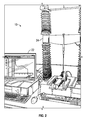
- friction tester 10 which is modified from a Texture Analyzer (available from Stable Micro Systems, London, England), is shown with all components in place. Cable 20 is connected to arm 24, and is run through pulley 12 and attached to sled 14. Friction tester 10 is operatively connected to a computer 22, which displays the results of the test.
- the friction tester 10 includes a linear transducer placed, for example which outputs a converted signal relative to the range of displacement that has taken place and a force transducer (such as a strain gage), to measure the force applied over a given distance.
- a speed at which the arm 24 moves vertically is set, and as the arm 24 is displaced, cable 20, through pulley 12, pulls sled 14 laterally through trough 18 and across the filtercake on filter paper 16.
- the trough 18 has a length of four inches, and the sled 14 weighs four pounds.
- any suitable system for measuring the force required to move the sled 14 may be used. While linear transducers and force transducers are disclosed, other suitable techniques for producing a force versus distance curve may be employed. In this embodiment, the linear displacement is measured, in order to assure that the filtercake remains in place against the sled 14. However, embodiments are not so limited, as the system may be arranged in a vertical fashion as well.
- the friction tester may be modified such that either the pulley or trough height is modified to create an angle of inclination between the two components. This angle may be selected to match the angle for a drilled well. In other words, rather than pulling the sled normal to the arm, the sled may be pulled at an angle that is equivalent to a drilled angle.
- the friction tester includes an adjustable height pulley, which can be raised or lowered as desired.
- the geometric or material aspects of one or more components may be modified to better emulate real-world conditions.
- the surface roughness of either the sled or the trough may be increased.
- the trough diameter or length may be increased or decreased.
- the overall shape of the trough may be modified to be less cylindrical.
- the sled may be modified to have different materials, dimensions, weight, and roughness, among other considerations.
- Figure 3 illustrates the result of one test as a force versus time curve.
- a high initial force is required.
- the force required to move sled 14 decreases significantly (which is a measure of the dynamic friction), and has a relatively flat progression until the test concludes.
- This embodiment therefore, provides a user with the measure of both the static and dynamic frictional forces encountered.
- a user can then repeat the test by modifying the filtercake (i.e., changing the fluids and/or additives used to create the filtercake), and looking at how the force versus distance curve is modified.
- a lubricant can be added to the mud, and the resultant effect on the force versus distance curve can be analyzed.
- the solids content of the mud may be increased or decreased to change the thickness of the filtercake.
- the curve can be modified to achieve a desired result, such as reducing, or eliminating the static peak, to eliminate the variability in the force required to pull a drillstring out of the hole.
- FIG. 4 shows a flowchart in accordance with an embodiment of the disclosure.
- a sled is pulled across a filtercake ST40.
- the force is measured, with a force gauge, and the distance is measured with a linear transducer ST42.
- the force versus distance curve is then output ST44.
- the filtercake may then be modified ST46, and the process repeated.
- modifying the filtercake may include adding a lubricant, changing the solids content, changing the base fluid, or any other technique to create or change the properties of a filtercake. This process may be repeated until an optimized curve is created.
- An optimized curve for example, may be one with a reduced static peak, or have a flat dynamic portion.
- Figures 5A and 5B illustrate two curves that may be preferable to the one shown in Figure 3 . Further, it is noted that Figure 3 shows force versus time, while Figures 5A and 5B show force versus distance. Because the speed of the sled is constant, the 'force vs time' and 'force vs distance' plot will be the same in this embodiment. What figures 5A and 5B demonstrate is a static frictional force that is nearly equal to the dynamic frictional force. Other aspects may be modified to produce a desired curve.
- raw data may be measured as distance or time, and may be converted to the other based on the speed of the pulling arm. Further, it is also within the scope of the present disclosure that the data may be considered in the form of a resistant force versus applied force curve. In any situation, the data may show the transition between static friction and kinetic or dynamic friction, and comparison of multiple curves may demonstrate a filtercake with which less friction or drag is created when a drill string assembly is pulled or pushed against the filtercake.
- the present disclosure may generally relate to formation and comparison of frictional force curves, which may include any type of frictional force curve, including force versus distance, force versus time, resistance force versus applied force, as well as any other type of curve that will indicate static and kinetic or dynamic frictional forces.
- embodiments of the present invention provide a quick and low cost method of testing the frictional forces for a variety of filtercakes, which can allow for the selection of improved fluids when drilling a well. Also, embodiments disclosed herein provide a way to test the lubricating properties of various additives, by looking at their resultant impact on the force versus distance curves generated by embodiments disclosed herein.
- embodiments of the present disclosure may provide an ability to predict the behavior of filtercakes prior to pulling the drillstring out of a hole. For example, a drilling company could request an analysis of the filtercake to determine whether they are likely to see a "stick" situation (where drilling pipe is caught by the static frictional force), to determine whether they need to pump additional lubricating material downhole to avoid this situation.
- embodiments disclosed herein can be used to assist with current drilling conditions, by predicting the behavior of filtercakes to allow a drilling company to make a decision about which additional additives should be used.
Landscapes
- Chemical & Material Sciences (AREA)
- Life Sciences & Earth Sciences (AREA)
- Health & Medical Sciences (AREA)
- Engineering & Computer Science (AREA)
- Immunology (AREA)
- Physics & Mathematics (AREA)
- Analytical Chemistry (AREA)
- Biochemistry (AREA)
- General Health & Medical Sciences (AREA)
- General Physics & Mathematics (AREA)
- Pathology (AREA)
- Automation & Control Theory (AREA)
- General Chemical & Material Sciences (AREA)
- Chemical Kinetics & Catalysis (AREA)
- Oil, Petroleum & Natural Gas (AREA)
- Food Science & Technology (AREA)
- Medicinal Chemistry (AREA)
- Filtration Of Liquid (AREA)
- Sampling And Sample Adjustment (AREA)
- Investigating Strength Of Materials By Application Of Mechanical Stress (AREA)
- Force Measurement Appropriate To Specific Purposes (AREA)
Abstract
Description
- In the drilling of boreholes such as oil or gas wells, a drilling fluid (hereinafter referred to as "drilling mud") is circulated through the well during drilling in order to, inter alia, remove drilled cuttings, balance the pressure of formation fluids to prevent influxes and maintain the stability of the borehole. In order to provide the required density and viscosity, the mud can include certain solids such as barite and bentonite as well as solids derived from the drilling action. When drilling oil and gas wells, it is quite common to encounter subterranean formations which are porous. If the hydrostatic pressure of the drilling fluid is greater than the pressure of fluids in such formations, mud will penetrate the formation. Generally the pore size of such formations is sufficient to admit the liquid components and very fine solids but to filter out the other solids such as barite or bentonite. These filtered solids form on the borehole wall as a filtercake. This filtercake grows and compacts until the differential pressure is balanced by the stress in the filtercake.
- The filtercake has a much lower permeability than the formation. Filtercake can therefore be useful as it acts as a barrier to prevent fluid loss from the drilling mud to the formation. A number of ways of forming filter cakes are known in the art, including the use of bridging particles, cuttings created by the drilling process, polymeric additives, and precipitates. Filtercakes, therefore, have different compositional structures, based on the additives, base fluid, and cuttings.
- If a filtercake becomes too thick, problems can occur. For example, filtercakes can be a significant contributor to differential sticking: if the drill string or bottomhole assembly (BHA) is allowed to rest against the wellbore wall, the filtercake can continue to grow around the contact point, and must be yielded in order to free the BHA. Emphasis has therefore been placed on developing thin, highly impermeable but weak filtercakes, which minimize their contribution to severity of differential sticking, and also ease clean-up in the reservoir section.
- During the drilling of a borehole through underground formations, the drill string assembly undergoes considerable sliding contact with both the steel casing and rock formations. This sliding contact results primarily from the rotational and axial movements of the drill string assembly in the borehole. Friction between the moving surface of the drill string assembly and the stationary surfaces of the casing and formation creates considerable drag on the drill string and results in excessive torque and drag during drilling operations. The problem caused by friction is inherent in any drilling operation, but it is especially troublesome in directionally drilled wells or extended reach drilling (ERD) wells. Directional drilling or ERD is the intentional deviation of a wellbore from the vertical. In some cases the angle from the vertical may be as great as ninety degrees from the vertical. Such wells are commonly referred to as horizontal wells and may be drilled to a considerable depth and considerable distance from the drilling platform. Friction between the drill string assembly and the wellbore walls is also observed when the drill bit (and assembly) is pulled out of hole.
- In all drilling operations, the drill string assembly has a tendency to rest against the side of the borehole or the well casing, but this tendency is much greater in directionally drilled wells because of the effect of gravity. As the drill string increases in length or degree of vertical deflection, the amount of friction created by the rotating drill string assembly also increases. To overcome this increase in friction, additional power is required to rotate the drill string assembly. In some cases, the friction between the drill string assembly and the casing wall or borehole exceeds the maximum torque that can be tolerated by the drill string assembly and/or maximum torque capacity of the drill rig and drilling operations must cease. Consequently, the depth to which wells can be drilled using available directional drilling equipment and techniques is limited.
- One method for reducing the friction caused by the contact between the drill string assembly and casing (in case of a cased hole) or borehole (in case of an open hole) is improving the lubricity of drilling muds. In industry drilling operations, attempts have been made to reduce friction through, mainly, using water and/or oil based mud solutions containing various types of expensive and often environmentally unfriendly additives. Diesel and other mineral oils are also often used as lubricants, but there is a problem with the disposal of the mud. Certain minerals such as bentonite are known to help reduce friction between the drill string assembly and an open borehole. Materials such as TEFLON® have been used to reduce friction, however these lack durability and strength. Other additives include vegetable oils, asphalt, graphite, detergents and walnut hulls, but each has its own limitations.
- This summary is provided to introduce a selection of concepts that are further described below in the detailed description. This summary is not intended to identify key or essential features of the claimed subject matter, nor is it intended to be used as an aid in limiting the scope of the claimed subject matter.
- In one aspect, embodiments disclosed herein relate to a method that includes pulling a sled disposed on a trough across a first filtercake at a constant speed, measuring a force versus distance or time based on the pulling; and outputting a frictional force curve.
- In another aspect, embodiments disclosed herein relate to a method that includes pulling a sled across a first filtercake at a constant speed, measuring a force versus distance or time, outputting a first frictional force curve, creating a second filtercake, pulling a sled across the second filtercake, measuring a force versus distance or time, outputting a second frictional force curve, comparing the first frictional force curve and the second frictional force curve, and selecting a drilling fluid based on the comparing.
- In another aspect, embodiments disclosed herein relate to an apparatus that includes a base, a pulley attached to the base, a trough attached to the base, a sled disposed on the trough, a cable connecting the pulley and the sled, the cable connected to an arm capable of being moved at a constant speed, and a system to measure the force required to move the sled.
- Other aspects and advantages of the claimed subject matter will be apparent from the following description and the appended claims.
-
-
Figure 1 shows components of a friction tester in accordance with an embodiment of the disclosure; -
Figure 2 shows an assembled friction tester in accordance with an embodiment of the disclosure; -
Figure 3 is a Force versus Time curve; -
Figure 4 is a flowchart in accordance with an embodiment of the disclosure; -
Figure 5A is a Force versus Distance curve; -
Figure 5B is a Force versus Distance curve; and - In one aspect, embodiments disclosed herein relate to methods and apparatuses for testing the frictional forces resulting from the interaction of drilling equipment with a filtercake. More specifically, embodiments disclosed herein relate to methods and apparatuses for testing the static frictional force encountered by a drill string (such as when changing the bit) when pulled against a filtercake. Various filtercakes can be analyzed to determine a friction profile and the overall lubricity (or lack thereof) of the filtercake formed by a given fluid.
- A suitable filtercake for use in embodiments disclosed herein may be made in accordance with the methodology disclosed in standard high temperature high pressure (HTHP) fluid loss tests, such as those according to the specifications of the American Petroleum Institute (API), as described in "Recommended Practice Standard Procedure for Field Testing Oil-Based Drilling Fluids," API Recommended Practice 13B-2 Third Edition, February 1998, Section 5.2.1 to 5.2.3; and "Recommended Practice Standard Procedure for Field Testing Water-Based Drilling Fluids," API Recommended Practice 13B-1 Second Edition, September 1997, Section 5.3.1 to 5.3.2.
- The API test employs a pressurized cell fitted with a standard hardened filter paper as a filtration medium. The filtration behavior of the drilling mud is determined with a standard pressure differential across the filter paper of 500 psi (3.45 M Pa). A filter cake is allowed to build up on the filter paper for 30 minutes. The filtercake can then be removed and used with the testing apparatus of the present disclosure. Various fluids may be used to create a number of various filtercakes for testing purposes. Further, the API test is a single way to form a filter cake that is often used in the drilling fluid industry; however, there is no limitation on the way in which a filtercake may be formed. Rather, one of ordinary skill in the art would appreciate that a filter cake may be built on any type of medium through which a fluid phase can pass and allow for the build-up of the fluid components as a cake on the medium. A standardized set of procedures may allow for fewer variations in the filtercake properties between filtercakes. For example, when evaluating the potential effect of different fluid components on the friction between the filtercake and a drill string assembly, use of a standardized filtercake test may allow for a more accurate assessment of the effect of the fluid components on the filtercake and friction generated.
- Turning to
Figure 1 , a partial view of one embodiment of afriction tester 10 for use in testing the frictional forces in filtercake / drill string interaction is shown. As illustrated, components of afriction tester 10 include apulley 12, attached to abase 11. Atrough 18 is also attached tobase 11. Asled 14, which emulates a drilling component such as a length of drilling pipe, is placed on thetrough 18. A filtercake onfilter paper 16 is disposed on thetrough 18 between thesled 14 andtrough 18. Thefilter paper 16 is held in place by a retaining member (not shown), such as a clamp. The retaining member may be any suitable device which can hold the filter paper in place. - The
sled 14 may be formed from a variety of drilling grade steels, or may be formed from any suitable material that may be used in drilling operations. Filtercake onfilter paper 16 is clamped into place so that it remains rigidly attached to thetrough 18.Trough 18 may be formed from the same material assled 14, or can be formed from a different material. - While a filtercake on
filter paper 16 is shown, those having ordinary skill in the art will appreciate that the filtercake may also be formed on other devices used to measure the properties of filtercakes, such aloxite disks. In addition, multiple sheets of filter paper with filtercakes may be used to increase the surface area of filtercake to interact withsled 14. The geometric properties of thetrough 18 or thesled 14 may be modified to have a "lip," (i.e., a raised portion that thesled 14 must pass over) have surface roughness, or other geometric properties to better approximate the real world conditions. In addition, the filtercake could be formed onto thesled 14, and pulled against thetrough 18. Moreover, whilesled 14 is shown as a generally cylindrical tube, there is no limitation imparted on the scope of the present disclosure by this shape. - Turning to
Figure 2 ,friction tester 10, which is modified from a Texture Analyzer (available from Stable Micro Systems, London, England), is shown with all components in place.Cable 20 is connected toarm 24, and is run throughpulley 12 and attached tosled 14.Friction tester 10 is operatively connected to acomputer 22, which displays the results of the test. Thefriction tester 10 includes a linear transducer placed, for example which outputs a converted signal relative to the range of displacement that has taken place and a force transducer (such as a strain gage), to measure the force applied over a given distance. In operation, a speed at which thearm 24 moves vertically is set, and as thearm 24 is displaced,cable 20, throughpulley 12, pullssled 14 laterally throughtrough 18 and across the filtercake onfilter paper 16. In one embodiment, thetrough 18 has a length of four inches, and thesled 14 weighs four pounds. - Those having ordinary skill in the art will appreciate that while one
friction tester 10 is shown, any suitable system for measuring the force required to move thesled 14 may be used. While linear transducers and force transducers are disclosed, other suitable techniques for producing a force versus distance curve may be employed. In this embodiment, the linear displacement is measured, in order to assure that the filtercake remains in place against thesled 14. However, embodiments are not so limited, as the system may be arranged in a vertical fashion as well. - One advantage of the present disclosure is the ability to change aspects of various components to better emulate real-world situations. For example, for a case where pipe is being removed from a deviated well, the friction tester may be modified such that either the pulley or trough height is modified to create an angle of inclination between the two components. This angle may be selected to match the angle for a drilled well. In other words, rather than pulling the sled normal to the arm, the sled may be pulled at an angle that is equivalent to a drilled angle. One of ordinary skill in the art will appreciate that the depth of the trough could also be similarly changed to achieve the same result. In one embodiment, therefore, the friction tester includes an adjustable height pulley, which can be raised or lowered as desired.
- Additionally, the geometric or material aspects of one or more components may be modified to better emulate real-world conditions. For example, the surface roughness of either the sled or the trough may be increased. The trough diameter or length may be increased or decreased. The overall shape of the trough may be modified to be less cylindrical. Additionally, the sled may be modified to have different materials, dimensions, weight, and roughness, among other considerations.
-
Figure 3 illustrates the result of one test as a force versus time curve. As can be seen fromFigure 3 , in order to overcome the initial static friction betweensled 14 and filtercake onfilter paper 16, a high initial force is required. After that initial static friction is overcome, the force required to movesled 14 decreases significantly (which is a measure of the dynamic friction), and has a relatively flat progression until the test concludes. - This embodiment, therefore, provides a user with the measure of both the static and dynamic frictional forces encountered. A user can then repeat the test by modifying the filtercake (i.e., changing the fluids and/or additives used to create the filtercake), and looking at how the force versus distance curve is modified. In one embodiment, for example, a lubricant can be added to the mud, and the resultant effect on the force versus distance curve can be analyzed. In addition, the solids content of the mud may be increased or decreased to change the thickness of the filtercake. By selecting various lubricants the curve can be modified to achieve a desired result, such as reducing, or eliminating the static peak, to eliminate the variability in the force required to pull a drillstring out of the hole.
-
Figure 4 shows a flowchart in accordance with an embodiment of the disclosure. InFigure 4 , a sled is pulled across a filtercake ST40. The force is measured, with a force gauge, and the distance is measured with a linear transducer ST42. The force versus distance curve is then output ST44. The filtercake may then be modified ST46, and the process repeated. As noted above, modifying the filtercake may include adding a lubricant, changing the solids content, changing the base fluid, or any other technique to create or change the properties of a filtercake. This process may be repeated until an optimized curve is created. An optimized curve, for example, may be one with a reduced static peak, or have a flat dynamic portion.Figures 5A and 5B illustrate two curves that may be preferable to the one shown inFigure 3 . Further, it is noted thatFigure 3 shows force versus time, whileFigures 5A and 5B show force versus distance. Because the speed of the sled is constant, the 'force vs time' and 'force vs distance' plot will be the same in this embodiment. Whatfigures 5A and 5B demonstrate is a static frictional force that is nearly equal to the dynamic frictional force. Other aspects may be modified to produce a desired curve. - One of ordinary skill in the art would appreciate that raw data may be measured as distance or time, and may be converted to the other based on the speed of the pulling arm. Further, it is also within the scope of the present disclosure that the data may be considered in the form of a resistant force versus applied force curve. In any situation, the data may show the transition between static friction and kinetic or dynamic friction, and comparison of multiple curves may demonstrate a filtercake with which less friction or drag is created when a drill string assembly is pulled or pushed against the filtercake. Thus, the present disclosure may generally relate to formation and comparison of frictional force curves, which may include any type of frictional force curve, including force versus distance, force versus time, resistance force versus applied force, as well as any other type of curve that will indicate static and kinetic or dynamic frictional forces.
- Based on this methodology, a number of filtercakes can be analyzed to determine which have the least force required to pull the drillstring, or have the most constant force, for example. Advantageously, embodiments of the present invention provide a quick and low cost method of testing the frictional forces for a variety of filtercakes, which can allow for the selection of improved fluids when drilling a well. Also, embodiments disclosed herein provide a way to test the lubricating properties of various additives, by looking at their resultant impact on the force versus distance curves generated by embodiments disclosed herein.
- Also advantageously, embodiments of the present disclosure may provide an ability to predict the behavior of filtercakes prior to pulling the drillstring out of a hole. For example, a drilling company could request an analysis of the filtercake to determine whether they are likely to see a "stick" situation (where drilling pipe is caught by the static frictional force), to determine whether they need to pump additional lubricating material downhole to avoid this situation. Thus, embodiments disclosed herein can be used to assist with current drilling conditions, by predicting the behavior of filtercakes to allow a drilling company to make a decision about which additional additives should be used.
- Although a few example embodiments have been described in detail above, those skilled in the art will readily appreciate that many modifications are possible in the example embodiments without materially departing from this invention. Accordingly, all such modifications are intended to be included within the scope of this disclosure as defined in the following claims. In the claims, means-plus-function clauses are intended to cover the structures described herein as performing the recited function and not only structural equivalents, but also equivalent structures. Thus, although a nail and a screw may not be structural equivalents in that a nail employs a cylindrical surface to secure wooden parts together, whereas a screw employs a helical surface, in the environment of fastening wooden parts, a nail and a screw may be equivalent structures. It is the express intention of the applicant not to invoke 35 U.S.C. § 112, paragraph 6 for any limitations of any of the claims herein, except for those in which the claim expressly uses the words 'means for' together with an associated function.
Claims (12)
- A method comprising:pulling a sled disposed on a trough across a first filtercake at a constant speed;measuring a force versus distance or time based on the pulling; andoutputting a frictional force curve.
- The method of claim 1, further comprising:repeating the pulling, measuring, and outputting with at least one other filtercake.
- The method of claim 2, wherein the repeating occurs until an optimized force versus distance curve is output.
- The method of any one of the preceding claims, further comprising:modifying the filtercake by increasing the thickness of the filtercake.
- The method of any one of the preceding claims, wherein the at least one other filtercake comes from a fluid having a different composition than the first filtercake.
- The method of any one of the preceding claims, further comprising:modifying a property of the sled or the trough, wherein the property comprises at least one selected from the group consisting of surface roughness, shape, length, diameter, weight, and a material that the sled or the trough is formed from.
- A method comprising:pulling a sled across a first filtercake at a constant speed;measuring a force versus distance or time;outputting a first frictional force curve;creating a second filtercake;pulling a sled across the second filtercake;measuring a force versus distance or time;outputting a second frictional force curve;comparing the first frictional force curve and the second frictional force curve; andselecting a drilling fluid based on the comparing.
- An apparatus comprising:a base;a pulley attached to the base;a trough attached to the base;a sled disposed on the trough;a cable connecting the pulley and the sled, the cable connected to an arm capable of being moved at a constant speed; anda system to measure the force required to move the sled.
- The apparatus of claim 8, wherein the pulley has an adjustable height.
- The apparatus of claim 8 or 9, further comprising a retaining member for holding a filtercake between the sled and the trough.
- The apparatus of any one of claims 8 to 10, further comprising a computer operatively connected to the apparatus.
- The apparatus of any one of claims 8 to 11, wherein the trough is adjustable.
Applications Claiming Priority (1)
| Application Number | Priority Date | Filing Date | Title |
|---|---|---|---|
| US201261747721P | 2012-12-31 | 2012-12-31 |
Publications (2)
| Publication Number | Publication Date |
|---|---|
| EP2749864A2 true EP2749864A2 (en) | 2014-07-02 |
| EP2749864A3 EP2749864A3 (en) | 2017-06-28 |
Family
ID=50031114
Family Applications (1)
| Application Number | Title | Priority Date | Filing Date |
|---|---|---|---|
| EP13199751.2A Withdrawn EP2749864A3 (en) | 2012-12-31 | 2013-12-30 | Filter cake drag tester |
Country Status (2)
| Country | Link |
|---|---|
| US (1) | US9513208B2 (en) |
| EP (1) | EP2749864A3 (en) |
Cited By (1)
| Publication number | Priority date | Publication date | Assignee | Title |
|---|---|---|---|---|
| CN105628604A (en) * | 2014-11-06 | 2016-06-01 | 中国石油化工股份有限公司 | Method for evaluating lubricating performances of horizontal well and extended reach well drilling fluids |
Families Citing this family (2)
| Publication number | Priority date | Publication date | Assignee | Title |
|---|---|---|---|---|
| US9528974B2 (en) * | 2013-10-11 | 2016-12-27 | Baker Hughes Incorporated | Friction apparatus and method for measuring lubricity of downhole fluids |
| US10655042B2 (en) | 2015-11-13 | 2020-05-19 | Schlumberger Norge As | Wellbore strengthening additive and uses thereof |
Family Cites Families (4)
| Publication number | Priority date | Publication date | Assignee | Title |
|---|---|---|---|---|
| US3977231A (en) * | 1975-06-09 | 1976-08-31 | The United States Of America As Represented By The Administrator Of The National Aeronautics And Space Administration | Static coefficient test method and apparatus |
| SU1499192A1 (en) * | 1987-07-06 | 1989-08-07 | Нижне-Волжский научно-исследовательский институт геологии и геофизики | Device for determining coefficient of friction of filtration incrustation |
| GB2448746B (en) * | 2007-04-26 | 2012-04-25 | Mi Llc | Rheological measurement of filtercake |
| RU128717U1 (en) * | 2012-10-25 | 2013-05-27 | Федеральное государственное бюджетное образовательное учреждение высшего профессионального образования "Уфимский государственный нефтяной технический университет" | DEVICE FOR CONTROL OF STATIC AND DYNAMIC FRICTION COEFFICIENT OF THE METAL-FILTRATION Crust COUPLE |
-
2013
- 2013-12-26 US US14/140,685 patent/US9513208B2/en not_active Expired - Fee Related
- 2013-12-30 EP EP13199751.2A patent/EP2749864A3/en not_active Withdrawn
Cited By (2)
| Publication number | Priority date | Publication date | Assignee | Title |
|---|---|---|---|---|
| CN105628604A (en) * | 2014-11-06 | 2016-06-01 | 中国石油化工股份有限公司 | Method for evaluating lubricating performances of horizontal well and extended reach well drilling fluids |
| CN105628604B (en) * | 2014-11-06 | 2019-03-15 | 中国石油化工股份有限公司 | Method for evaluating the lubricating properties of drilling fluids for horizontal and extended-reach wells |
Also Published As
| Publication number | Publication date |
|---|---|
| US9513208B2 (en) | 2016-12-06 |
| US20140290330A1 (en) | 2014-10-02 |
| EP2749864A3 (en) | 2017-06-28 |
Similar Documents
| Publication | Publication Date | Title |
|---|---|---|
| Hakim et al. | Performance of polyethylene and polypropylene beads towards drill cuttings transportation in horizontal wellbore | |
| Busahmin et al. | Review on hole cleaning for horizontal wells | |
| Sanghani et al. | Rheology of foam and its implications in drilling and cleanout operations | |
| US10209169B2 (en) | Method and apparatus for automatically testing high pressure and high temperature sedimentation of slurries | |
| Ward et al. | Pressure-while-drilling data improve reservoir drilling performance | |
| Bol | Effect of mud composition on wear and friction of casing and tool joints | |
| Reid et al. | Differential-sticking mechanisms and a simple wellsite test for monitoring and optimizing drilling mud properties | |
| AU5279702A (en) | Method for determining real-time downhole mud properties while drilling | |
| Gautam et al. | Prediction of high-pressure/high-temperature rheological properties of drilling fluids from the viscosity data measured on a coaxial cylinder viscometer | |
| Saasen | Hole cleaning during deviated drilling-The effects of pump rate and rheology | |
| Maidla et al. | Laboratory study of borehole friction factor with a dynamic-filtration apparatus | |
| US9513208B2 (en) | Filter cake drag tester | |
| Isambourg et al. | Down-hole simulation cell for measurement of lubricity and differential pressure sticking | |
| Martin Brown et al. | An extensive scope of flow loops with a focus on particle transport | |
| Chen et al. | A new method for determining the minimum gas injection rate required for hole cleaning in horizontal gas drilling | |
| Ytrehus et al. | Experimental study of cuttings transport efficiency of water based drilling fluids | |
| Oseh et al. | Effect of Nanoparticles in Drilling Fluids on the Transportation of Different Cutting Sizes in a Rotating Horizontal Pipe | |
| Noah | Optimizing drilling fluid properties and flow rates for effective hole cleaning at high-angle and horizontal wells | |
| Young et al. | Effects of offshore sampling and testing on undrained soil shear strength | |
| Izuwa | Evaluating the impact of rheological property of local viscosifier on hole cleaning | |
| Rahman et al. | Analysis of a drilling mud-based system on the common problems related to coiled tubing application in slim-hole oil wells | |
| Fereidounpour et al. | A field study, laboratory test and cost estimation of solid and liquid lubricants in directional wells to reduce friction coefficient and improve ROP | |
| Deng | Assessment of drilling fluid hole cleaning capacity in horizontal directional drilling–a parametric study of the effects of drilling fluid additives | |
| Zamora | Mechanisms, measurement and mitigation of barite sag | |
| Jaffal | Evaluation of mudcake buildup and its mechanical properties |
Legal Events
| Date | Code | Title | Description |
|---|---|---|---|
| 17P | Request for examination filed |
Effective date: 20131230 |
|
| AK | Designated contracting states |
Kind code of ref document: A2 Designated state(s): AL AT BE BG CH CY CZ DE DK EE ES FI FR GB GR HR HU IE IS IT LI LT LU LV MC MK MT NL NO PL PT RO RS SE SI SK SM TR |
|
| AX | Request for extension of the european patent |
Extension state: BA ME |
|
| PUAI | Public reference made under article 153(3) epc to a published international application that has entered the european phase |
Free format text: ORIGINAL CODE: 0009012 |
|
| PUAL | Search report despatched |
Free format text: ORIGINAL CODE: 0009013 |
|
| AK | Designated contracting states |
Kind code of ref document: A3 Designated state(s): AL AT BE BG CH CY CZ DE DK EE ES FI FR GB GR HR HU IE IS IT LI LT LU LV MC MK MT NL NO PL PT RO RS SE SI SK SM TR |
|
| AX | Request for extension of the european patent |
Extension state: BA ME |
|
| RIC1 | Information provided on ipc code assigned before grant |
Ipc: G01N 19/02 20060101AFI20170522BHEP Ipc: G01N 33/28 20060101ALI20170522BHEP Ipc: E21B 41/00 20060101ALI20170522BHEP |
|
| STAA | Information on the status of an ep patent application or granted ep patent |
Free format text: STATUS: THE APPLICATION IS DEEMED TO BE WITHDRAWN |
|
| 18D | Application deemed to be withdrawn |
Effective date: 20180103 |