EP2749530A1 - Calcium carbide granules, process for producing calcium carbide granules, and system for producing calcium carbide granules - Google Patents
Calcium carbide granules, process for producing calcium carbide granules, and system for producing calcium carbide granules Download PDFInfo
- Publication number
- EP2749530A1 EP2749530A1 EP20120826254 EP12826254A EP2749530A1 EP 2749530 A1 EP2749530 A1 EP 2749530A1 EP 20120826254 EP20120826254 EP 20120826254 EP 12826254 A EP12826254 A EP 12826254A EP 2749530 A1 EP2749530 A1 EP 2749530A1
- Authority
- EP
- European Patent Office
- Prior art keywords
- calcium carbide
- granules
- carbide
- screen
- crushing machine
- Prior art date
- Legal status (The legal status is an assumption and is not a legal conclusion. Google has not performed a legal analysis and makes no representation as to the accuracy of the status listed.)
- Granted
Links
Images
Classifications
-
- C—CHEMISTRY; METALLURGY
- C01—INORGANIC CHEMISTRY
- C01B—NON-METALLIC ELEMENTS; COMPOUNDS THEREOF; METALLOIDS OR COMPOUNDS THEREOF NOT COVERED BY SUBCLASS C01C
- C01B32/00—Carbon; Compounds thereof
- C01B32/90—Carbides
- C01B32/914—Carbides of single elements
- C01B32/942—Calcium carbide
Definitions
- the invention relates to calcium carbide granules, a method for producing calcium carbide granules, and a system for producing calcium carbide granules, and more particularly to calcium carbide granules suitable for dry acetylene generation, and a method and a system for producing such calcium carbide granules.
- Patent Document 1 Chinese Patent Document CN101100617A
- an object of the invention is to provide calcium carbide granules, a calcium carbide granule producing method and a calcium carbide granule producing system, which, in the dry acetylene generation, would not lead to an increased security risk due to raised reaction temperature, and would not increase a secondarily generated reaction such as acetylene polymerization and not have adverse influence on the yield.
- in one aspect of the invention provides calcium carbide granules wherein a content of the granules having granule size of 4 mm or more is 5 wt% or less and a content of the granules having granule size of 0.15 mm or less is 20 wt% or less.
- a content of the carbide granules having a granule size of 4 mm or more is 5 wt% or less and a content of the granules having granule size of 0.15 mm or less is 20 wt% or less.
- an average granule size can be preferably set between 0.8 mm and 1.5 mm.
- the reaction temperature at the acetylene being generated may rise and the secondarily generated reaction may increase.
- the average granule size exceeds 1.5 mm, the acetylene generation yield may be reduced.
- Another aspect of the invention provides a method for producing calcium carbide granules wherein a content of the granules having granule size of 4 mm or more is 5 wt% or less and a content of the granules having granule size of 0.15 mm or less is 20 wt% or less, the method comprising: A) crushing calcium carbides by a crushing machine; B) passing the calcium carbide crushed by the crushing machine through a screen having a mesh size of 4 mm; and C) reintroducing the calcium carbide remaining on the screen into the crushing machine again, wherein the steps A, B and C are carried out in an inactive gas atmosphere.
- the mesh size of the screen is 4 mm, a small amount of the carbide granules of 4 mm or more may pass through the screen.
- Carbide is easily weathered in air and tends to generate acetylene gas when the carbide is in contact with water.
- the operations for crushing, feeding and storing the carbide are carried out in an inactive gas atmosphere.
- the inactive gas nitrogen, helium and the like can be used.
- the inventors have found out that a content of the carbide powders with a granule size of 0.15 mm or less can be suppressed to 20 wt% or less by crushing the granules relatively roughly by the crushing machine so that the crushed granularity is not excessively fine and intentionally a certain amount of the carbide cannot pass through the screen, and by returning the certain amount of the carbides to the crushing machine.
- carbide powders having a granule diameter of 0.15 mm or less tend to increase in the crushing operation by the crushing machine, in which carbide powders with a particle size of 0.15 mm or less may exceed 20 wt%.
- carbide powders with a particle size of 0.15 mm or less may exceed 20 wt%.
- the circulation ratio exceeds 2.5 there is a tendency that the production efficiency of the carbide granules may decrease and carbide powders with a particle size of 4 mm or more may increase, in which they may exceed 5 wt%.
- the amount of foreign substances such as iron matters, which are removed after passing through the crushing machine and before passing through the screen may be ignored because the above amount is extremely small as compared with the carbide amount.
- One embodiment of the invention includes a step of removing foreign substances from the calcium carbide after the step A and before the step B. This step removes iron matters and the like which may be included in the carbide. Thus, this removal would reduce the load of the crushing machine and net damage of the screen.
- Still another aspect of the invention provides a system for producing calcium carbide granules, in an inactive gas atmosphere, wherein a content of granules having the granule size of 4 mm or more is 5 wt% or less and a content of the granules having granule size of 0.15 mm or less is 20 wt% or less, the system comprising: a crushing machine for crushing calcium carbides; a screen for passing the calcium carbide crushed by the crushing machine through it, the screen having a screen size of 4 mm; and a carbide return path for reintroducing the calcium carbide remaining on the screen into the crushing machine again.
- the system can include a foreign substance removing machine (an iron removing machine and the like) for removing foreign substances from the calcium carbide between the crushing machine and the screen.
- the crushing machine can comprise: a rotor which a rotor which is rotatable around a rotor shaft and has a plurality of hitting members on the periphery of the rotor; breaking plates having uneven breaking liners on an arc-like inner side facing the rotor; and a means for oil cooling the rotor.
- a means for oil cooling the rotor shaft one that can pass a cooling oil through retainers in bearings for the rotor shaft and the like can be preferably used.
- One embodiment of the invention includes a flow conveyer for feeding the calcium carbide which has passed through the screen to raw material sealing tanks via intermediate tanks, each of the raw material sealing tanks being associated with a dry acetylene generator, wherein the flow conveyer comprises: a casing which extends in the left-and-right direction; an upper forth path and a lower back path, which are partitioned in the up-and-down manner by a partition within the casing and are in communication with each other through a communicating port at a left or right end of the casing; and an inactive gas supplying means for supplying an inactive gas to the forth path so as to deliver the gas through in turn the forth path, the communicating port and then the back path, wherein the casing has an inlet of the calcium carbide at a part corresponding to the forth path, openings with which the raw material sealing tanks are connected, and an outlet of the calcium carbide, the openings and the outlet being at parts corresponding to the back path, and wherein the calcium carbide introduced to the forth path via the inlet is delivered through
- the intermediate tanks are arranged between the screen and the flow conveyer and can serve to adjust a carbide amount to be sent to the raw material sealing tanks while storing the carbide granules.
- As the intermediate tanks it is possible to use a tank for receiving the carbide from the screen and another separate tank for receiving the carbide returned from the flow conveyer.
- a feeding means e.g. vertically feeder and the like
- the flow conveyer is used as a means for finally delivering the carbide to the raw material sealing tanks.
- two screw conveyers were needed for sending and returning carbide to and from the raw material sealing tanks.
- calcium carbide granules wherein a content of the granules having a granule size of 4 mm or more is 5 wt% or less and a content of the granules having a granule size of 0.15 mm or less is 20 wt% or less.
- the carbide in the granularity range (% is on the basis of the mass) would not raise the security risk because of a rise in the reaction temperature in dry acetylene generation. Also, this would not increase secondarily generated reaction such as acetylene polymerization and not have an adverse influence on the yield.
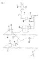
- Fig. 1 is an explanation view showing a carbide granule producing system according to one embodiment of the invention.
- the carbide granule producing system is intended to produce carbide granules suitable for dry acetylene generation and to supply the produced carbide granules to dry acetylene generators (not shown).
- the system comprises: a stock tank 10 for receiving carbides via a receiving feeder 1 and a vertical feeder 2, the carbides having a granule size of 40 mm or less (a content of the granules having a granule size of 40 to 50 mm is 3 wt% or less) after carbide masses were preliminarily broken; a crushing machine 20 for crushing the carbides introduced from the stock tank 10; a screen 30 having a mesh size of 4 mm which is applied to the carbide crushed by the crushing machine 20; a return path 40 for reintroducing the carbide which has remained on the screen 30 into the crushing machine 20 again; and raw material tanks (first intermediate tanks) 50 for storing the carbide granules having passed through the screen 30.
- the carbide granule producing system further includes a screw conveyer 8, a vertical feeder 9 and a flow conveyer 60, which serve to deliver the carbide granules from the raw material tanks 50 to raw material sealing tanks 70 associated with dry acetylene generators, and a return tank (second intermediate tank) 80 for storing the carbide granules which have overflowed the raw material sealing tanks 70.
- each of the raw material sealing tank 70 is associated with each of the dry acetylene generator.
- the reference number 3 indicates a vibration feeder
- the number 5 indicates a vertical feeder
- the numbers 7 and 11 indicate rotary valves
- the number 12 indicates a screw conveyer.
- Two or more crushing machines 20 and two or more raw material tanks 50, etc. can be used in parallel.
- the operations for crushing, feeding and storing the carbide are carried out in nitrogen atmosphere from which water component has been eliminated in order to avoid the weathering of carbide and the explosion of acetylene.
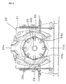
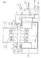
- Figs. 2 and 3 are a front cross-section explanation view and a side cross-section explanation view of the crushing machine 20, respectively.
- the crushing machine 20 is one which is configured similarly to an impact type crushing machine as described in e.g. JP,2004-82045,A , in addition to an oil cooling mechanism added to the one as described later.
- the crushing machine 20 comprises: a box-shaped casing 21, which includes a feed port 21a at its top and a discharge port 21b at its bottom; a rotor 22 inside the casing 21, which has a plurality of (eight in Fig.
- the target granularity of the carbide crushed by the crushing machine 20 can be set with a certain precision by adjusting the clearance between the hitting plates 22a of the rotor 22 and the breaking liners 23a of the breaking plates 23 and the rotation number of the rotor.
- the clearance between the hitting plates 22a and the breaking liners 23 can be adjusted separately in an upper stage (upper part) and a lower stage (lower part).
- the crushing machine 20 is operated such that the carbides are crushed relatively roughly so that the crushed granularity is not excessively fine (carbide granules having a granule size of 0.15 mm or less will not exceed 20 wt%), and that a certain amount of the carbides will be circulated into the crushing machine 20 through the return path 40 without passing through the screen 30.
- the carbide crushed by the crushing machine 20 is passed through the screen 30 after iron matters are removed by the iron removing machine 6.
- the screen 30 allows the carbide having a granule size of 0.4 mm or less to pass through it and does not allow the carbide with a granule size greater than 0.4 mm (a small amount of the carbide with a granule size above 4 mm may pass through the screen).
- the carbides which has remained on the screen 30 without passing through it are reintroduced into the crushing machine 20 through the return path 40.
- the amount of foreign substances such as iron matters, which are removed after passing through the crushing machine and before passing through the screen, is ignored because the above amount is extremely small as compared with the carbide amount. Consequently, in the raw material tanks 50, there are stored the carbide granules in which a granule size of of 4 mm or more is 5 wt% or less; a granule size of 0.15 mm or less is 20 wt% or less; and an average granule size is between 0.8 mm and 1.5 mm.
- the casing 21 is filled with nitrogen and hermetically sealed. Further, there are disposed ground packing members 24 (see Fig. 3 ) between a front wall 21c and a rear wall 21d of the casing 21 and the rotor shaft 22b respectively to enhance the sealing property. Also, there would be a danger such that the reducing tendency of the carbide increases if the temperature of the rotor shaft 22b rose due to the crushing heat from the carbide. To avoid this, the crushing machine 20 includes an oil circulation circuit (schematically shown in Fig.
- the oil circulation circuit comprises: an oil cooler unit 26 disposed outside the casing 21 of the crushing machine 20; feed lines 27a and 27b for feeding the lubricant oil of a relatively low temperature to the front and rear bearings 25a and 25b, respectively, from the oil cooler unit 26; and return lines 28a and 28b for returning the lubricant oil from the front and rear bearings 25a and 25b to the oil cooler unit 26, the temperature of the returning oil being relatively high by heat exchanging with the bearings.
- the oil cooler unit 26 has: an oil tank 26a to which the feed lines 27a and 27b and the return lines 28a and 28b are connected; an oil pump 26b for sending the oil inside the oil tank 26a through the feed lines 27a and 27b; a heat exchanger 26c that is provided in the feeding lines 27a and 27b to cool the oil by heat exchanging with ambient air; and a fan 26d for blowing ambient air to the heat exchanger 26c. Since carbide is water-prohibitive, water cooling is unsuitable.
- the carbide granules as stored in the raw material tanks 50 are supplied to a plurality of raw material sealing tanks 70 by the screw conveyer 8, the vertical feeder 9 and the flow conveyer 60
- Each of the raw material sealing tanks 70 is associated with a dry acetylene generator unshown in a one-to-one relationship.
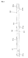
- Fig. 4 is a side explanation view of the flow conveyer 60.
- the flow conveyer 60 includes an upper forth path 62 and a lower back path 63, which are partitioned in the up-and-down manner by an intermediate partition 64 within a horizontally long casing 61 having a rectangular cross-section.
- the partition 64 is disconnected at a right end within the casing 61 so as to form a communicating port 64a through which the forth path 62 and the back path 63 are in communication with each other.
- an inlet 61a for receiving the carbide granules from the vertical feeder 9.
- openings 61b and an outlet 61c are formed in an upper wall of the casing 61.
- Each of the openings 61b is connected with the upper end of each of the raw material sealing tanks 70.
- the outlet 61c is for returning the carbide granules which were not able to be contained in the raw material sealing tanks 70 to the return tank 80.
- the nitrogen is introduced by a nitrogen supply into the casing 61 through near the left end of the forth path 62.
- the nitrogen flows from the left to the right in the forth path 62, goes into the back path 63 through at the communicating port 64a, and then flows from the right to the left in the back path 63.
- the carbide granules introduced from the inlet 61a into the forth path 62 are delivered to the communicating port 64a at the right side in the forth path 62 and then conveyed from the right side to the outlet 61c at the left side in the back path 63.
- the carbide granules When the carbide granules are being moved leftward in the back path 63, they fall into the raw material sealing tanks 70 through the openings 61b and then fill the tanks.
- the carbide granules overflowing the raw material sealing tanks 70 are delivered leftward in the back path 63 and then returned to the return tank 80 through the outlet 61c.
- Each of the raw material sealing tanks 70 is always filled with the carbide granules, and such carbides as densely contained can function as a material seal for protecting acetylene gas from flowing into the raw material sealing tanks 70.
- the carbide granules returned to the return tank 80 are properly reintroduced to the raw material sealing tanks 70.
- the clearance of the upper stage between the hitting plates 22a of the rotor 22 and the breaking liners 23a of the breaking plates 23 was set to 50 mm
- the clearance of the lower stage was set to 30 mm
- the rotation number of the rotor 22 was set to 45 m/s (650 rpm).
- the carbides were introduced at 40 t/h from the feed port 21a.
- the table 1 shows a granularity (granule size) distribution (based on the mass) of the carbide granules (having passed through the screen 30) obtained by operating the crushing machine 20 for a long time at this circulation ratio.
- Screen (mm) 4.75 or more 4.0 or more 4.0 to 3.0 3.0 to 2.0 2.0 to 1.0 1.0 to 0.5 0.5 to 0.15 0.15 or less
- Ratio (%) 0.0 0.2 13.5 17.4 25.2 15.0 22.6 6.2
- the reaction temperature indicated here is a solid phase temperature inside the generator when 3 equivalents of water are sprayed to the carbide and acetylene gas is being generated.
- the generation yield is a value when the generated gas amount is divided by the theoretical generation amount (the used carbide amount x the generated acetylene gas amount). As this value is higher, it is indicated that the acetylene gas is being generated more efficiently.
- the remaining carbide is a value indicating, as a generated acetylene gas amount, a carbide amount remaining in hydrated lime without reacting. As this value is lower, it is indicated that the carbide is being used more effectively.
- the security risk would increase at a post process of the hydrated lime.
- the clearance of the upper stage between the hitting plates 22a of the rotor 22 and the breaking liners 23a of the breaking plates 23 was set to 40 mm
- the clearance of the lower stage was set to 20 mm
- the rotation number of the rotor 22 was set to 45 m/s (650 rpm).
- the carbides were introduced at 27 t/h from the feed port 21 a.
- the table 2 shows a granularity distribution (based on the mass) of the carbide granules (having passed through the screen 30) obtained by operating the crushing machine 20 for a long time at this circulation ratio.
- Screen (mm) 4.75 or more 4.0 or more 4.0 to 3.0 3.0 to 2.0 2.0 to 1.0 1.0 to 0.5 0.5 to 0.15 0.15 or less
- Ratio (%) 0.0 0.1 5.2 11.3 15.0 24.5 20.3 23.6
- the carbide is excessively fine, increasing the reaction temperature and the security risk.
- the clearance of the upper stage between the hitting plates 22a of the rotor 22 and the breaking liners 23a of the breaking plates 23 was set to 60 mm
- the clearance of the lower stage was set to 35 mm
- the rotation number of the rotor 22 was set to 45 m/s (650 rpm).
- the carbides were introduced at 60 t/h from the feed port 21 a.
- the table 3 shows a granularity distribution (based on the mass) of the carbide granules (having passed through the screen 30) obtained by operating the crushing machine 20 for a long time at this circulation ratio.
- Screen (mm) 4.75 or more 4.0 or more 4.0 to 3.0 3.0 to 2.0 2.0 to 1.0 1.0 to 0.5 0.5 to 0.15 0.15 or less
- Ratio (%) 1.5 4.2 25.2 17.5 21.5 15.5 12.4
- the remaining non-reactive carbide is great, which may reduce the yield of the acetylene gas.
- the clearance of the upper stage between the hitting plates 22a of the rotor 22 and the breaking liners 23a of the breaking plates 23 was set to 55 mm
- the clearance of the lower stage was set to 32 mm
- the rotation number of the rotor 22 was set to 45 m/s (650 rpm).
- the carbides were introduced at 52.5 t/h from the feed port 21a.
- the table 4 shows a granularity distribution (based on the mass) of the carbide granules (having passed through the screen 30) obtained by operating the crushing machine 20 for a long time at this circulation ratio.
- Screen (mm) 4.75 or more 4.0 or more 4.0 to 3.0 3.0 to 2.0 2.0 to 1.0 1.0 to 0.5 0.5 to 0.15 0.15 or less
- Ratio (%) 1.2 3.8 21.7 18.8 21.5 15.4 14.1
- Average Granule Size 1.5 mm Circulation Ratio: 2.5 Reaction Temperature: 122 °C Generation Yield: 95.66 % Remaining Carbide: 1500 ml/kg
- the clearance of the upper stage between the hitting plates 22a of the rotor 22 and the breaking liners 23a of the breaking plates 23 was set to 45 mm
- the clearance of the lower stage was set to 22 mm
- the rotation number of the rotor 22 was set to 45 m/s (650 rpm).
- the carbides were introduced at 30 t/h from the feed port 21 a.
- the table 5 shows a granularity distribution (based on the mass) of the carbide granules (having passed through the screen 30) obtained by operating the crushing machine 20 for a long time at this circulation ratio.
- Screen (mm) 4.75 or more 4.0 or more 4.0 to 3.0 3.0 to 2.0 2.0 to 1.0 1.0 to 0.5 0.5 to 0.15 0.15 or less
- Ratio (%) 0.0 0.1 6.3 15.5 19.7 21.1 17.3 20.0
Landscapes
- Chemical & Material Sciences (AREA)
- Organic Chemistry (AREA)
- Inorganic Chemistry (AREA)
- Carbon And Carbon Compounds (AREA)
- Crushing And Pulverization Processes (AREA)
- Crushing And Grinding (AREA)
Abstract
Description
- The invention relates to calcium carbide granules, a method for producing calcium carbide granules, and a system for producing calcium carbide granules, and more particularly to calcium carbide granules suitable for dry acetylene generation, and a method and a system for producing such calcium carbide granules.
- When calcium carbide (hereinafter referred to as merely "carbide") is supplied to an acetylene generator for dry acetylene generation, carbide masses are preliminarily broken and then the resulting carbides are introduced into a crushing machine to be crushed in fines. This carbide is delivered to raw material sealing tanks located above acetylene generators. With regard to the carbide, as its granularity is finer, its reactivity at the acetylene being generated further increases, and the material sealing function to protect acetylene gas from flowing into a raw material sealing tank further improves because of the carbide densely contained in the raw material sealing tank. For this reason, conventionally, the granularity or granule size of the carbide was made as fine as possible by the crushing machine and a screen. With regard to the granularity of the carbide, Chinese Patent Document
CN 101100617A discloses that the granularity is 3 mm or less and 1 mm or less is 70 % or more. Further, conventionally, since the carbide is delivered to raw material sealing tanks by a screw conveyer, another screw conveyer is needed to return the carbide overflowing the raw material sealing tanks to intermediate tanks. - [Patent Document 1] Chinese Patent Document
CN101100617A - However, the inventors have found out that, when the granularity of carbide is excessively fine, a reaction temperature at the acetylene being generated rises, increasing a security risk, and also a secondarily generated reaction such as acetylene polymerization increases, adversely affecting the yield of acetylene gas. Therefore, an object of the invention is to provide calcium carbide granules, a calcium carbide granule producing method and a calcium carbide granule producing system, which, in the dry acetylene generation, would not lead to an increased security risk due to raised reaction temperature, and would not increase a secondarily generated reaction such as acetylene polymerization and not have adverse influence on the yield.
- To solve the above-mentioned problems, in one aspect of the invention provides calcium carbide granules wherein a content of the granules having granule size of 4 mm or more is 5 wt% or less and a content of the granules having granule size of 0.15 mm or less is 20 wt% or less. As a percentage of the carbide granules having a granule size of 4 mm or more increases, non-reactive carbide in an acetylene generator may increase, which may reduce the yield of acetylene gas. When the content of the carbide having a granule size of 0.15 mm or less exceeds 20 wt%, the reaction temperature of the acetylene being generated may rise, which may raise the security risk and increase secondarily generated reaction such as acetylene polymerization in the acetylene generator. This may also decrease the yield of the acetylene gas. Moreover, in the invention, an average granule size can be preferably set between 0.8 mm and 1.5 mm. When the average granule size of the carbide is less than 0.8 mm, the reaction temperature at the acetylene being generated may rise and the secondarily generated reaction may increase. On the other hand, when the average granule size exceeds 1.5 mm, the acetylene generation yield may be reduced.
- Another aspect of the invention provides a method for producing calcium carbide granules wherein a content of the granules having granule size of 4 mm or more is 5 wt% or less and a content of the granules having granule size of 0.15 mm or less is 20 wt% or less, the method comprising: A) crushing calcium carbides by a crushing machine; B) passing the calcium carbide crushed by the crushing machine through a screen having a mesh size of 4 mm; and C) reintroducing the calcium carbide remaining on the screen into the crushing machine again, wherein the steps A, B and C are carried out in an inactive gas atmosphere. Even if the mesh size of the screen is 4 mm, a small amount of the carbide granules of 4 mm or more may pass through the screen. Carbide is easily weathered in air and tends to generate acetylene gas when the carbide is in contact with water. Thus, the operations for crushing, feeding and storing the carbide are carried out in an inactive gas atmosphere. As the inactive gas, nitrogen, helium and the like can be used.
- In the method for producing calcium carbide granules according to the invention, the granularity (granule size) as crushed by the crushing machine can be controlled such that a calcium carbide amount a which is introduced into the crushing machine at the step A and a calcium carbide amount b which has passed through the screen at the step B have a relation of (a-b)lb = 1 to 2.5. The inventors have found out that a content of the carbide powders with a granule size of 0.15 mm or less can be suppressed to 20 wt% or less by crushing the granules relatively roughly by the crushing machine so that the crushed granularity is not excessively fine and intentionally a certain amount of the carbide cannot pass through the screen, and by returning the certain amount of the carbides to the crushing machine. That is, the crushing machine is operated with a circulation ratio = (a-b)lb = clb = 1 to 2.5: where a denotes a carbide amount introduced into the crushing machine (introduced raw material amount) ; b denotes a carbide amount that has passed through the screen (production amount) with respect to the amount a; and c denotes a carbide amount that is returned to the crushing machine without having passed through the screen (circulation amount) with respect to the amount a. When the circulation ratio is less than 1, carbide powders having a granule diameter of 0.15 mm or less tend to increase in the crushing operation by the crushing machine, in which carbide powders with a particle size of 0.15 mm or less may exceed 20 wt%. On the other hand, when the circulation ratio exceeds 2.5, there is a tendency that the production efficiency of the carbide granules may decrease and carbide powders with a particle size of 4 mm or more may increase, in which they may exceed 5 wt%. Here, the amount of foreign substances such as iron matters, which are removed after passing through the crushing machine and before passing through the screen, may be ignored because the above amount is extremely small as compared with the carbide amount.
- One embodiment of the invention includes a step of removing foreign substances from the calcium carbide after the step A and before the step B. This step removes iron matters and the like which may be included in the carbide. Thus, this removal would reduce the load of the crushing machine and net damage of the screen.
- Still another aspect of the invention provides a system for producing calcium carbide granules, in an inactive gas atmosphere, wherein a content of granules having the granule size of 4 mm or more is 5 wt% or less and a content of the granules having granule size of 0.15 mm or less is 20 wt% or less, the system comprising: a crushing machine for crushing calcium carbides; a screen for passing the calcium carbide crushed by the crushing machine through it, the screen having a screen size of 4 mm; and a carbide return path for reintroducing the calcium carbide remaining on the screen into the crushing machine again. In the system for producing calcium carbide granules according to the invention, granule sizes as crushed by the crushing machine can be controlled such that a calcium carbide amount a which is introduced into the crushing machine and the calcium carbide amount b which has passed through the screen have a relation of (a-b)lb = 1 to 2.5. Moreover, the system can include a foreign substance removing machine (an iron removing machine and the like) for removing foreign substances from the calcium carbide between the crushing machine and the screen.
- In the invention, the crushing machine can comprise: a rotor which a rotor which is rotatable around a rotor shaft and has a plurality of hitting members on the periphery of the rotor; breaking plates having uneven breaking liners on an arc-like inner side facing the rotor; and a means for oil cooling the rotor. As the means for oil cooling the rotor shaft, one that can pass a cooling oil through retainers in bearings for the rotor shaft and the like can be preferably used.
- One embodiment of the invention includes a flow conveyer for feeding the calcium carbide which has passed through the screen to raw material sealing tanks via intermediate tanks, each of the raw material sealing tanks being associated with a dry acetylene generator, wherein the flow conveyer comprises: a casing which extends in the left-and-right direction; an upper forth path and a lower back path, which are partitioned in the up-and-down manner by a partition within the casing and are in communication with each other through a communicating port at a left or right end of the casing; and an inactive gas supplying means for supplying an inactive gas to the forth path so as to deliver the gas through in turn the forth path, the communicating port and then the back path, wherein the casing has an inlet of the calcium carbide at a part corresponding to the forth path, openings with which the raw material sealing tanks are connected, and an outlet of the calcium carbide, the openings and the outlet being at parts corresponding to the back path, and wherein the calcium carbide introduced to the forth path via the inlet is delivered through in turn the forth path, the communicating port and then the back path; the calcium carbide being delivered through the back path fills the raw material sealing tanks from the openings; and the calcium carbide overflowing the raw material sealing tanks is returned to one of more of the intermediate tanks from the outlet. The intermediate tanks are arranged between the screen and the flow conveyer and can serve to adjust a carbide amount to be sent to the raw material sealing tanks while storing the carbide granules. As the intermediate tanks, it is possible to use a tank for receiving the carbide from the screen and another separate tank for receiving the carbide returned from the flow conveyer. To feed the carbide from the intermediate tanks to the raw material sealing tanks, a feeding means (e.g. vertically feeder and the like) other than the above flow conveyer may be used. However, in an embodiment of the invention, the flow conveyer is used as a means for finally delivering the carbide to the raw material sealing tanks. Conventionally, two screw conveyers were needed for sending and returning carbide to and from the raw material sealing tanks. However, by using one flow conveyer including the forth and back paths together, it is possible to obtain an advantage such as reduced facility cost.
- In the invention, there are provided calcium carbide granules wherein a content of the granules having a granule size of 4 mm or more is 5 wt% or less and a content of the granules having a granule size of 0.15 mm or less is 20 wt% or less. The carbide in the granularity range (% is on the basis of the mass) would not raise the security risk because of a rise in the reaction temperature in dry acetylene generation. Also, this would not increase secondarily generated reaction such as acetylene polymerization and not have an adverse influence on the yield.
-
-
Fig. 1 is an explanation view showing a carbide granule producing system according to an embodiment of the invention. -
Fig. 2 is a front cross-section explanation view of a crushing machine. -
Fig. 3 is a side cross-section explanation view of the crushing machine, to which a schematic oil circulation circuit is added. -
Fig. 4 is a side cross-section explanation view of a flow conveyer. - A preferable embodiment of the invention will be described below with reference to the drawings. However, the invention is not limited to the embodiment.
Fig. 1 is an explanation view showing a carbide granule producing system according to one embodiment of the invention. The carbide granule producing system is intended to produce carbide granules suitable for dry acetylene generation and to supply the produced carbide granules to dry acetylene generators (not shown). The system comprises: astock tank 10 for receiving carbides via a receiving feeder 1 and avertical feeder 2, the carbides having a granule size of 40 mm or less (a content of the granules having a granule size of 40 to 50 mm is 3 wt% or less) after carbide masses were preliminarily broken; a crushingmachine 20 for crushing the carbides introduced from thestock tank 10; ascreen 30 having a mesh size of 4 mm which is applied to the carbide crushed by the crushingmachine 20; areturn path 40 for reintroducing the carbide which has remained on thescreen 30 into the crushingmachine 20 again; and raw material tanks (first intermediate tanks) 50 for storing the carbide granules having passed through thescreen 30. Between thestock tank 10 and the crushingmachine 20 and between the crushingmachine 20 and thescreen 30, there are disposed magnet type iron removing machines 4 and 6 for removing foreign substances such as iron matters that may be included in the carbide. As iron matters are removed by the iron removing machines 4 and 6, the load of the crushingmachine 20 and a possible break of the screen net can be reduced. The carbide granule producing system further includes a screw conveyer 8, a vertical feeder 9 and aflow conveyer 60, which serve to deliver the carbide granules from theraw material tanks 50 to rawmaterial sealing tanks 70 associated with dry acetylene generators, and a return tank (second intermediate tank) 80 for storing the carbide granules which have overflowed the rawmaterial sealing tanks 70. In this embodiment, there are a plurality of rawmaterial sealing tanks 70, and each of the rawmaterial sealing tank 70 is associated with each of the dry acetylene generator. InFig. 1 , the reference number 3 indicates a vibration feeder, the number 5 indicates a vertical feeder, thenumbers 7 and 11 indicate rotary valves, and thenumber 12 indicates a screw conveyer. Two or more crushingmachines 20 and two or moreraw material tanks 50, etc. can be used in parallel. In the carbide granule producing system, the operations for crushing, feeding and storing the carbide are carried out in nitrogen atmosphere from which water component has been eliminated in order to avoid the weathering of carbide and the explosion of acetylene. -
Figs. 2 and3 are a front cross-section explanation view and a side cross-section explanation view of the crushingmachine 20, respectively. The crushingmachine 20 is one which is configured similarly to an impact type crushing machine as described in e.g.JP,2004-82045,A machine 20 comprises: a box-shapedcasing 21, which includes afeed port 21a at its top and adischarge port 21b at its bottom; arotor 22 inside thecasing 21, which has a plurality of (eight inFig. 2 ) hittingplates 22a on its periphery and is rotatable around arotor shaft 22b in one and the other directions; and breakingplates 23 that are disposed on the left and right sides of therotor 22 within thecasing 21 and haveuneven breaking liners 23a with bumps and dips on their respective arc-like inner sides facing therotor 22. In the crushingmachine 20, the carbides fed from thefeed port 21a is broken between the hittingplates 22a of therotating rotor 22 and thebreaking liners 23a of the breakingplates 23, and then discharged from thedischarge port 21b. The target granularity of the carbide crushed by the crushingmachine 20 can be set with a certain precision by adjusting the clearance between the hittingplates 22a of therotor 22 and thebreaking liners 23a of the breakingplates 23 and the rotation number of the rotor. The clearance between the hittingplates 22a and thebreaking liners 23 can be adjusted separately in an upper stage (upper part) and a lower stage (lower part). In this embodiment, the crushingmachine 20 is operated such that the carbides are crushed relatively roughly so that the crushed granularity is not excessively fine (carbide granules having a granule size of 0.15 mm or less will not exceed 20 wt%), and that a certain amount of the carbides will be circulated into the crushingmachine 20 through thereturn path 40 without passing through thescreen 30. - The carbide crushed by the crushing
machine 20 is passed through thescreen 30 after iron matters are removed by the iron removing machine 6. Thescreen 30 allows the carbide having a granule size of 0.4 mm or less to pass through it and does not allow the carbide with a granule size greater than 0.4 mm (a small amount of the carbide with a granule size above 4 mm may pass through the screen). The carbides which has remained on thescreen 30 without passing through it are reintroduced into the crushingmachine 20 through thereturn path 40. In this embodiment, the granularity (granule size) by the crushing machine is controlled to be a circulation ratio = (a-b)lb = c/b = 1 to 2.5: where a denotes a carbide amount introduced into the crushingmachine 20 from the stock tank 10 (introduced raw material amount) ; b denotes a carbide amount that has passed through the screen 30 (production amount) with respect to the amount a; and c denotes a carbide amount that is returned to the crushing machine without having passed through the screen (circulation amount) with respect to the amount a. Here, the amount of foreign substances such as iron matters, which are removed after passing through the crushing machine and before passing through the screen, is ignored because the above amount is extremely small as compared with the carbide amount. Consequently, in theraw material tanks 50, there are stored the carbide granules in which a granule size of of 4 mm or more is 5 wt% or less; a granule size of 0.15 mm or less is 20 wt% or less; and an average granule size is between 0.8 mm and 1.5 mm. - In the crushing
machine 20, to avoid the weathering of the carbide and the explosion of acetylene, thecasing 21 is filled with nitrogen and hermetically sealed. Further, there are disposed ground packing members 24 (seeFig. 3 ) between afront wall 21c and arear wall 21d of thecasing 21 and therotor shaft 22b respectively to enhance the sealing property. Also, there would be a danger such that the reducing tendency of the carbide increases if the temperature of therotor shaft 22b rose due to the crushing heat from the carbide. To avoid this, the crushingmachine 20 includes an oil circulation circuit (schematically shown inFig. 3 ) as described below for oil cooling by introducing a lubricant oil through (the retainers of) the front andrear bearings Fig. 3 ) and carrying out the oil cooling. The oil circulation circuit comprises: an oilcooler unit 26 disposed outside thecasing 21 of the crushingmachine 20;feed lines rear bearings oil cooler unit 26; andreturn lines rear bearings oil cooler unit 26, the temperature of the returning oil being relatively high by heat exchanging with the bearings. Theoil cooler unit 26 has: anoil tank 26a to which thefeed lines return lines oil pump 26b for sending the oil inside theoil tank 26a through thefeed lines heat exchanger 26c that is provided in thefeeding lines fan 26d for blowing ambient air to theheat exchanger 26c. Since carbide is water-prohibitive, water cooling is unsuitable. - The carbide granules as stored in the
raw material tanks 50 are supplied to a plurality of rawmaterial sealing tanks 70 by the screw conveyer 8, the vertical feeder 9 and theflow conveyer 60 Each of the rawmaterial sealing tanks 70 is associated with a dry acetylene generator unshown in a one-to-one relationship.Fig. 4 is a side explanation view of theflow conveyer 60. Theflow conveyer 60 includes an upperforth path 62 and alower back path 63, which are partitioned in the up-and-down manner by anintermediate partition 64 within a horizontallylong casing 61 having a rectangular cross-section. Thepartition 64 is disconnected at a right end within thecasing 61 so as to form a communicatingport 64a through which theforth path 62 and theback path 63 are in communication with each other. In an upper wall of thecasing 61, there is provided aninlet 61a for receiving the carbide granules from the vertical feeder 9. In a bottom wall of thecasing 61,openings 61b and anoutlet 61c are formed. Each of theopenings 61b is connected with the upper end of each of the rawmaterial sealing tanks 70. Theoutlet 61c is for returning the carbide granules which were not able to be contained in the rawmaterial sealing tanks 70 to thereturn tank 80. The nitrogen is introduced by a nitrogen supply into thecasing 61 through near the left end of theforth path 62. The nitrogen flows from the left to the right in theforth path 62, goes into theback path 63 through at the communicatingport 64a, and then flows from the right to the left in theback path 63. By the nitrogen flowing, the carbide granules introduced from theinlet 61a into theforth path 62 are delivered to the communicatingport 64a at the right side in theforth path 62 and then conveyed from the right side to theoutlet 61c at the left side in theback path 63. When the carbide granules are being moved leftward in theback path 63, they fall into the rawmaterial sealing tanks 70 through theopenings 61b and then fill the tanks. The carbide granules overflowing the rawmaterial sealing tanks 70 are delivered leftward in theback path 63 and then returned to thereturn tank 80 through theoutlet 61c. Each of the rawmaterial sealing tanks 70 is always filled with the carbide granules, and such carbides as densely contained can function as a material seal for protecting acetylene gas from flowing into the rawmaterial sealing tanks 70. The carbide granules returned to thereturn tank 80 are properly reintroduced to the rawmaterial sealing tanks 70. - In the above-mentioned crushing
machine 20, the clearance of the upper stage between the hittingplates 22a of therotor 22 and thebreaking liners 23a of the breakingplates 23 was set to 50 mm, the clearance of the lower stage was set to 30 mm, and the rotation number of therotor 22 was set to 45 m/s (650 rpm). Then, the carbides were introduced at 40 t/h from thefeed port 21a. The carbide amount that has passed through thescreen 30 after being crushed by the crushingmachine 20 became 15 t/h, and therefore the circulation ratio was (40-15)/15 = about 1.7. The table 1 shows a granularity (granule size) distribution (based on the mass) of the carbide granules (having passed through the screen 30) obtained by operating the crushingmachine 20 for a long time at this circulation ratio.[Table 1] Screen (mm) 4.75 or more 4.0 or more 4.0 to 3.0 3.0 to 2.0 2.0 to 1.0 1.0 to 0.5 0.5 to 0.15 0.15 or less Ratio (%) 0.0 0.2 13.5 17.4 25.2 15.0 22.6 6.2
Reaction Temperature: 127 °C
Generation Yield: 96.0 %
Remaining Carbides: 900 ml/kg - The reaction temperature indicated here is a solid phase temperature inside the generator when 3 equivalents of water are sprayed to the carbide and acetylene gas is being generated. As the temperature increases, the security risk rises. Also, the generation yield is a value when the generated gas amount is divided by the theoretical generation amount (the used carbide amount x the generated acetylene gas amount). As this value is higher, it is indicated that the acetylene gas is being generated more efficiently. Further, the remaining carbide is a value indicating, as a generated acetylene gas amount, a carbide amount remaining in hydrated lime without reacting. As this value is lower, it is indicated that the carbide is being used more effectively. On the other hand, when the value is high, the security risk would increase at a post process of the hydrated lime.
- In the crushing
machine 20, the clearance of the upper stage between the hittingplates 22a of therotor 22 and thebreaking liners 23a of the breakingplates 23 was set to 40 mm, the clearance of the lower stage was set to 20 mm, and the rotation number of therotor 22 was set to 45 m/s (650 rpm). Then, the carbides were introduced at 27 t/h from thefeed port 21 a. The carbide amount that has passed through thescreen 30 after being crushed by the crushingmachine 20 became 15 t/h, and therefore the circulation ratio was (27-15) /15 = 0.8. The table 2 shows a granularity distribution (based on the mass) of the carbide granules (having passed through the screen 30) obtained by operating the crushingmachine 20 for a long time at this circulation ratio.[Table 2] Screen (mm) 4.75 or more 4.0 or more 4.0 to 3.0 3.0 to 2.0 2.0 to 1.0 1.0 to 0.5 0.5 to 0.15 0.15 or less Ratio (%) 0.0 0.1 5.2 11.3 15.0 24.5 20.3 23.6
Reaction Temperature: 147 °C
Generation Yield: 94.3 %
Remaining Carbide: 300 ml/kg - In this case, the carbide is excessively fine, increasing the reaction temperature and the security risk.
- In the crushing
machine 20, the clearance of the upper stage between the hittingplates 22a of therotor 22 and thebreaking liners 23a of the breakingplates 23 was set to 60 mm, the clearance of the lower stage was set to 35 mm, and the rotation number of therotor 22 was set to 45 m/s (650 rpm). Then, the carbides were introduced at 60 t/h from thefeed port 21 a. The carbide amount that has passed through thescreen 30 after being crushed by the crushingmachine 20 became 15 t/h, and therefore the circulation ratio was (60-15) /15 = 3.0. The table 3 shows a granularity distribution (based on the mass) of the carbide granules (having passed through the screen 30) obtained by operating the crushingmachine 20 for a long time at this circulation ratio.[Table 3] Screen (mm) 4.75 or more 4.0 or more 4.0 to 3.0 3.0 to 2.0 2.0 to 1.0 1.0 to 0.5 0.5 to 0.15 0.15 or less Ratio (%) 1.5 4.2 25.2 17.5 21.5 15.5 12.4 2.2
Circulation Ratio: 3.0
Reaction Temperature: 119 °C
Generation Yield: 94.5 %
Remaining Carbide: 2500 ml/kg - In this case, the remaining non-reactive carbide is great, which may reduce the yield of the acetylene gas.
- In the crushing
machine 20, the clearance of the upper stage between the hittingplates 22a of therotor 22 and thebreaking liners 23a of the breakingplates 23 was set to 55 mm, the clearance of the lower stage was set to 32 mm, and the rotation number of therotor 22 was set to 45 m/s (650 rpm). Then, the carbides were introduced at 52.5 t/h from thefeed port 21a. The carbide amount that has passed through thescreen 30 after being crushed by the crushingmachine 20 became 15 t/h, and therefore the circulation ratio was (52.5-15)/15 = 2.5. The table 4 shows a granularity distribution (based on the mass) of the carbide granules (having passed through the screen 30) obtained by operating the crushingmachine 20 for a long time at this circulation ratio.[Table 4] Screen (mm) 4.75 or more 4.0 or more 4.0 to 3.0 3.0 to 2.0 2.0 to 1.0 1.0 to 0.5 0.5 to 0.15 0.15 or less Ratio (%) 1.2 3.8 21.7 18.8 21.5 15.4 14.1 3.5
Circulation Ratio: 2.5
Reaction Temperature: 122 °C
Generation Yield: 95.66 %
Remaining Carbide: 1500 ml/kg - In the crushing
machine 20, the clearance of the upper stage between the hittingplates 22a of therotor 22 and thebreaking liners 23a of the breakingplates 23 was set to 45 mm, the clearance of the lower stage was set to 22 mm, and the rotation number of therotor 22 was set to 45 m/s (650 rpm). Then, the carbides were introduced at 30 t/h from thefeed port 21 a. The carbide amount that has passed through thescreen 30 after being crushed by the crushingmachine 20 became 15 t/h, and therefore the circulation ratio was (30-15)/15 = 1.0. The table 5 shows a granularity distribution (based on the mass) of the carbide granules (having passed through the screen 30) obtained by operating the crushingmachine 20 for a long time at this circulation ratio.[Table 5] Screen (mm) 4.75 or more 4.0 or more 4.0 to 3.0 3.0 to 2.0 2.0 to 1.0 1.0 to 0.5 0.5 to 0.15 0.15 or less Ratio (%) 0.0 0.1 6.3 15.5 19.7 21.1 17.3 20.0
Circulation Ratio: 1.0
Reaction Temperature: 138 °C
Generation Yield: 95.4 %
Remaining Carbide: 500 ml/kg -
- 4, 6
- Iron Removing Machine
- 10
- Stock Tank
- 20
- Crushing Machine
- 21
- Casing
- 22
- Rotor
- 22a
- Hitting Plate
- 22b
- Rotor Shaft
- 23a
- Breaking Liner
- 25a, 25b
- Bearing
- 26
- Oil Cooler Unit
- 27a, 27b
- Feed Line
- 28a, 28b
- Return Line
- 30
- Screen
- 40
- Return Path
- 50
- Raw Material Tank
- 60
- Flow Conveyer
- 61
- Casing
- 62
- Forth Path
- 63
- Back Path
- 64
- Partition
- 64a
- Communicating Port
- 70
- Raw Material Sealing Tank
- 80
- Return Tank
Claims (10)
- Calcium carbide granules wherein a content of the granules having a granule size of 4 mm or more is 5 wt% or less and a content of the granules having a granule size of 0.15 mm or less is 20 wt% or less.
- The calcium carbide granules in claim 1, wherein an average granule size is between 0.8 mm and 1.5 mm.
- A method for producing calcium carbide granules wherein a content of the granules having granule size of 4 mm or more is 5 wt% or less and a content of the granules having granule size of 0.15 mm or less is 20 wt% or less, the method comprising:A) crushing calcium carbides by a crushing machine;B) passing the calcium carbide crushed by the crushing machine through a screen having a mesh size of 4 mm; andC) reintroducing the calcium carbides remaining on the screen into the crushing machine again,wherein the steps A, B and C are carried out in an inactive gas atmosphere.
- The method in claim 3, wherein the granularity as crushed by the crushing machine is controlled such that a calcium carbide amount a which is introduced into the crushing machine at the step A and a calcium carbide amount b which has passed through the screen at the step B have a relation of (a-b)lb = 1 to 2.5.
- The method in claim 3 or 4, including a step of removing foreign substances from the calcium carbides after the step A and before the step B.
- A system for producing calcium carbide granules, in an inactive gas atmosphere, wherein a content of the granules having granule size of 4 mm or more is 5 wt% or less and a content of the granules having granule size of 0.15 mm or less is 20 wt% or less , the system comprising:a crushing machine for crushing calcium carbides;a screen for passing the calcium carbide crushed by the crushing machine through it, the screen having a screen size of 4 mm; anda carbide return path for reintroducing the calcium carbides remaining on the screen into the crushing machine again.
- The system in claim 6, wherein the granularity as crushed by the crushing machine is controlled such that a calcium carbide amount a which is introduced into the crushing machine and a calcium carbide amount b which has passed through the screen have a relation of (a-b)/b = 1 to 2.5.
- The system in claim 6 or 7, including a foreign substance removing machine for removing foreign substances from the calcium carbides between the crushing machine and the screen.
- The system in any one of claims 6 to 8, wherein the crushing machine comprises: a rotor which is rotatable around a rotor shaft and has a plurality of hitting members on the periphery of the rotor; breaking plates having uneven breaking liners on an arc-like inner side facing the rotor; and a means for oil cooling the rotor.
- The system in any one of claims 6 to 9, including a flow conveyer for feeding the calcium carbide which has passed through the screen to raw material sealing tanks via intermediate tanks, each of the raw material sealing tanks being associated with a dry acetylene generator,
wherein the flow conveyer comprises: a casing which extends in the left-and-right direction; an upper forth path and a lower back path, which are partitioned in the up-and-down manner by a partition within the casing and are in communication with each other through a communicating port at a left or right end of the casing; and an inactive gas supplying means for supplying an inactive gas to the forth path so as to deliver the gas through in turn the forth path, the communicating port and then the back path,
wherein the casing has an inlet of the calcium carbide at a part corresponding to the forth path, openings with which the raw material sealing tanks are connected, and an outlet of the calcium carbide, the openings and the outlet being at parts corresponding to the back path, and
wherein the calcium carbide introduced to the forth path via the inlet is delivered through in turn the forth path, the communicating port and then the back path; the calcium carbide being delivered through the back path fills the raw material sealing tanks from the openings; and the calcium carbide overflowing the raw material sealing tanks is returned to one or more of the intermediate tanks from the outlet.
Applications Claiming Priority (2)
| Application Number | Priority Date | Filing Date | Title |
|---|---|---|---|
| JP2011183661 | 2011-08-25 | ||
| PCT/JP2012/052716 WO2013027426A1 (en) | 2011-08-25 | 2012-02-07 | Calcium carbide granules, process for producing calcium carbide granules, and system for producing calcium carbide granules |
Publications (3)
| Publication Number | Publication Date |
|---|---|
| EP2749530A1 true EP2749530A1 (en) | 2014-07-02 |
| EP2749530A4 EP2749530A4 (en) | 2015-05-27 |
| EP2749530B1 EP2749530B1 (en) | 2018-01-24 |
Family
ID=47746184
Family Applications (1)
| Application Number | Title | Priority Date | Filing Date |
|---|---|---|---|
| EP12826254.0A Active EP2749530B1 (en) | 2011-08-25 | 2012-02-07 | Process for producing calcium carbide granules |
Country Status (5)
| Country | Link |
|---|---|
| EP (1) | EP2749530B1 (en) |
| JP (1) | JP5909493B2 (en) |
| CN (1) | CN103764559B (en) |
| IN (1) | IN2014MN00516A (en) |
| WO (1) | WO2013027426A1 (en) |
Families Citing this family (5)
| Publication number | Priority date | Publication date | Assignee | Title |
|---|---|---|---|---|
| CN103754872B (en) * | 2013-12-17 | 2015-09-23 | 南京盛鹏炉料厂 | A kind of calcium carbide powder dry method granulation processes |
| CN107934967A (en) * | 2017-12-29 | 2018-04-20 | 神雾环保技术股份有限公司 | The system and method for coproduction ferrosilicon and calcium carbide |
| CN108313771A (en) * | 2018-04-12 | 2018-07-24 | 唐山三友氯碱有限责任公司 | It unloads for calcium carbide, feeding and broken device |
| WO2026029150A1 (en) * | 2024-07-31 | 2026-02-05 | デンカ株式会社 | Acetylene, method for producing acetylene, and acetylene derivative |
| WO2026029148A1 (en) * | 2024-07-31 | 2026-02-05 | デンカ株式会社 | Metal carbide and method for producing metal carbide |
Family Cites Families (10)
| Publication number | Priority date | Publication date | Assignee | Title |
|---|---|---|---|---|
| DE1935567B2 (en) * | 1969-07-12 | 1971-05-13 | Knapsack AG, 5033 Hurth Knapsack | PROCESS FOR THE PRODUCTION OF CALCIUM CARBIDE OF CERTAIN QUALITY |
| DE2037758C3 (en) * | 1970-07-30 | 1979-08-02 | Hoechst Ag, 6000 Frankfurt | Process for the production of calcium carbide for the desulfurization of metal melts |
| FR2482578A1 (en) * | 1980-05-17 | 1981-11-20 | Hoechst Ag | PROCESS FOR COOLING MOLTEN CALCIUM CARBIDE AND APPARATUS FOR IMPLEMENTING SAID METHOD |
| JPS5888112A (en) * | 1981-11-16 | 1983-05-26 | ナシヨナル・リサ−チ・アンド・デイベロツプメント・インコ−ポレイテツイド | Manufacture of calcium carbide product |
| JPS61178412A (en) * | 1985-02-02 | 1986-08-11 | Agency Of Ind Science & Technol | Production of calcium carbide by blast furnace process |
| JP3622117B2 (en) * | 2002-08-28 | 2005-02-23 | 川崎重工業株式会社 | Impact crusher |
| FR2856611A1 (en) * | 2003-06-26 | 2004-12-31 | Heurgue Conseil S A | Grains crushing process for use in grinder, involves pouring out product evacuated from lower part of enclosure, on sieve, and recycling residue that is not crushed, to upper part of enclosure |
| CN100537723C (en) | 2007-02-08 | 2009-09-09 | 寿光新龙电化集团聚氯乙烯有限公司 | A kind of technology of producing acetylene gas by dry method |
| CN101195555A (en) * | 2007-03-06 | 2008-06-11 | 新疆天业(集团)有限公司 | Acetylene generating system of dry method |
| CN201195120Y (en) * | 2008-05-23 | 2009-02-18 | 邹功全 | Calcium carbide crusher with automatic deferrization |
-
2012
- 2012-02-07 IN IN516MUN2014 patent/IN2014MN00516A/en unknown
- 2012-02-07 JP JP2013529909A patent/JP5909493B2/en active Active
- 2012-02-07 CN CN201280041501.3A patent/CN103764559B/en active Active
- 2012-02-07 WO PCT/JP2012/052716 patent/WO2013027426A1/en not_active Ceased
- 2012-02-07 EP EP12826254.0A patent/EP2749530B1/en active Active
Also Published As
| Publication number | Publication date |
|---|---|
| EP2749530B1 (en) | 2018-01-24 |
| CN103764559A (en) | 2014-04-30 |
| JPWO2013027426A1 (en) | 2015-03-05 |
| WO2013027426A1 (en) | 2013-02-28 |
| EP2749530A4 (en) | 2015-05-27 |
| IN2014MN00516A (en) | 2015-06-19 |
| JP5909493B2 (en) | 2016-04-26 |
| CN103764559B (en) | 2016-04-13 |
Similar Documents
| Publication | Publication Date | Title |
|---|---|---|
| EP2749530B1 (en) | Process for producing calcium carbide granules | |
| RU2762953C2 (en) | Cooling of bulk material | |
| CN107250078B (en) | A device for recycling white slag produced in steel production steps | |
| US20180094335A1 (en) | Cooling device for cooling bulk material | |
| KR102246861B1 (en) | Apparatus for milling powder | |
| US9365906B2 (en) | Process and device for charging into a smelting unit | |
| KR20130058876A (en) | Device for sealing driving shaft | |
| CN208087502U (en) | A kind of production equipment of lime nitrogen | |
| CN108484293A (en) | A kind of composite fertilizer's automatic production line | |
| JP5642589B2 (en) | Melting furnace for metal production and metal melting method using the same | |
| JPH06108104A (en) | Production of rare earth magnet and its device | |
| KR100645082B1 (en) | Industrial Waste Recycling Method and Molding Apparatus Used in The Same | |
| CN202599106U (en) | Sinter crushing system | |
| RU2685837C1 (en) | Apparatus for hot briquetting | |
| KR20130050430A (en) | Discharging apparatus for hopper and method for discharging sintering mixture raw matrials into hopper | |
| JP2004346414A (en) | Blast furnace charging equipment | |
| CN119634027B (en) | Control method of semi-self-grinding-stubborn stone crushing loop | |
| CN215396221U (en) | Flame retardant material production system | |
| CN219132874U (en) | Matting agent conveying device | |
| CN208104453U (en) | A kind of discharge system of coal base shaft furnace | |
| TWI886699B (en) | Flow control system for shaft furnace bunker and operating method thereof | |
| CN220560397U (en) | Silicon-manganese alloy casting device | |
| CN212441594U (en) | Cement manufacture is with broken and homogenization device in advance | |
| WO2013028264A1 (en) | Rotary feeder | |
| CN116710199A (en) | Funnel including cooling element |
Legal Events
| Date | Code | Title | Description |
|---|---|---|---|
| PUAI | Public reference made under article 153(3) epc to a published international application that has entered the european phase |
Free format text: ORIGINAL CODE: 0009012 |
|
| 17P | Request for examination filed |
Effective date: 20140324 |
|
| AK | Designated contracting states |
Kind code of ref document: A1 Designated state(s): AL AT BE BG CH CY CZ DE DK EE ES FI FR GB GR HR HU IE IS IT LI LT LU LV MC MK MT NL NO PL PT RO RS SE SI SK SM TR |
|
| DAX | Request for extension of the european patent (deleted) | ||
| RA4 | Supplementary search report drawn up and despatched (corrected) |
Effective date: 20150428 |
|
| RIC1 | Information provided on ipc code assigned before grant |
Ipc: C01B 31/32 20060101AFI20150421BHEP Ipc: B01J 2/20 20060101ALI20150421BHEP |
|
| 17Q | First examination report despatched |
Effective date: 20150522 |
|
| RAP1 | Party data changed (applicant data changed or rights of an application transferred) |
Owner name: DENKA COMPANY LIMITED |
|
| REG | Reference to a national code |
Ref country code: DE Ref legal event code: R079 Ref document number: 602012042450 Country of ref document: DE Free format text: PREVIOUS MAIN CLASS: C01B0031320000 Ipc: B01J0002200000 |
|
| GRAP | Despatch of communication of intention to grant a patent |
Free format text: ORIGINAL CODE: EPIDOSNIGR1 |
|
| RIC1 | Information provided on ipc code assigned before grant |
Ipc: C01B 32/942 20170101ALI20170822BHEP Ipc: B01J 2/20 20060101AFI20170822BHEP |
|
| INTG | Intention to grant announced |
Effective date: 20170926 |
|
| GRAS | Grant fee paid |
Free format text: ORIGINAL CODE: EPIDOSNIGR3 |
|
| GRAA | (expected) grant |
Free format text: ORIGINAL CODE: 0009210 |
|
| AK | Designated contracting states |
Kind code of ref document: B1 Designated state(s): AL AT BE BG CH CY CZ DE DK EE ES FI FR GB GR HR HU IE IS IT LI LT LU LV MC MK MT NL NO PL PT RO RS SE SI SK SM TR |
|
| REG | Reference to a national code |
Ref country code: GB Ref legal event code: FG4D |
|
| REG | Reference to a national code |
Ref country code: CH Ref legal event code: EP |
|
| REG | Reference to a national code |
Ref country code: AT Ref legal event code: REF Ref document number: 965475 Country of ref document: AT Kind code of ref document: T Effective date: 20180215 |
|
| REG | Reference to a national code |
Ref country code: IE Ref legal event code: FG4D |
|
| REG | Reference to a national code |
Ref country code: DE Ref legal event code: R096 Ref document number: 602012042450 Country of ref document: DE |
|
| REG | Reference to a national code |
Ref country code: SE Ref legal event code: TRGR |
|
| REG | Reference to a national code |
Ref country code: NL Ref legal event code: MP Effective date: 20180124 |
|
| REG | Reference to a national code |
Ref country code: LT Ref legal event code: MG4D |
|
| REG | Reference to a national code |
Ref country code: AT Ref legal event code: MK05 Ref document number: 965475 Country of ref document: AT Kind code of ref document: T Effective date: 20180124 |
|
| PG25 | Lapsed in a contracting state [announced via postgrant information from national office to epo] |
Ref country code: NL Free format text: LAPSE BECAUSE OF FAILURE TO SUBMIT A TRANSLATION OF THE DESCRIPTION OR TO PAY THE FEE WITHIN THE PRESCRIBED TIME-LIMIT Effective date: 20180124 |
|
| PG25 | Lapsed in a contracting state [announced via postgrant information from national office to epo] |
Ref country code: NO Free format text: LAPSE BECAUSE OF FAILURE TO SUBMIT A TRANSLATION OF THE DESCRIPTION OR TO PAY THE FEE WITHIN THE PRESCRIBED TIME-LIMIT Effective date: 20180424 Ref country code: FI Free format text: LAPSE BECAUSE OF FAILURE TO SUBMIT A TRANSLATION OF THE DESCRIPTION OR TO PAY THE FEE WITHIN THE PRESCRIBED TIME-LIMIT Effective date: 20180124 Ref country code: HR Free format text: LAPSE BECAUSE OF FAILURE TO SUBMIT A TRANSLATION OF THE DESCRIPTION OR TO PAY THE FEE WITHIN THE PRESCRIBED TIME-LIMIT Effective date: 20180124 Ref country code: LT Free format text: LAPSE BECAUSE OF FAILURE TO SUBMIT A TRANSLATION OF THE DESCRIPTION OR TO PAY THE FEE WITHIN THE PRESCRIBED TIME-LIMIT Effective date: 20180124 Ref country code: CY Free format text: LAPSE BECAUSE OF FAILURE TO SUBMIT A TRANSLATION OF THE DESCRIPTION OR TO PAY THE FEE WITHIN THE PRESCRIBED TIME-LIMIT Effective date: 20180124 Ref country code: ES Free format text: LAPSE BECAUSE OF FAILURE TO SUBMIT A TRANSLATION OF THE DESCRIPTION OR TO PAY THE FEE WITHIN THE PRESCRIBED TIME-LIMIT Effective date: 20180124 |
|
| PG25 | Lapsed in a contracting state [announced via postgrant information from national office to epo] |
Ref country code: IS Free format text: LAPSE BECAUSE OF FAILURE TO SUBMIT A TRANSLATION OF THE DESCRIPTION OR TO PAY THE FEE WITHIN THE PRESCRIBED TIME-LIMIT Effective date: 20180524 Ref country code: BG Free format text: LAPSE BECAUSE OF FAILURE TO SUBMIT A TRANSLATION OF THE DESCRIPTION OR TO PAY THE FEE WITHIN THE PRESCRIBED TIME-LIMIT Effective date: 20180424 Ref country code: GR Free format text: LAPSE BECAUSE OF FAILURE TO SUBMIT A TRANSLATION OF THE DESCRIPTION OR TO PAY THE FEE WITHIN THE PRESCRIBED TIME-LIMIT Effective date: 20180425 Ref country code: AT Free format text: LAPSE BECAUSE OF FAILURE TO SUBMIT A TRANSLATION OF THE DESCRIPTION OR TO PAY THE FEE WITHIN THE PRESCRIBED TIME-LIMIT Effective date: 20180124 Ref country code: LV Free format text: LAPSE BECAUSE OF FAILURE TO SUBMIT A TRANSLATION OF THE DESCRIPTION OR TO PAY THE FEE WITHIN THE PRESCRIBED TIME-LIMIT Effective date: 20180124 Ref country code: RS Free format text: LAPSE BECAUSE OF FAILURE TO SUBMIT A TRANSLATION OF THE DESCRIPTION OR TO PAY THE FEE WITHIN THE PRESCRIBED TIME-LIMIT Effective date: 20180124 Ref country code: PL Free format text: LAPSE BECAUSE OF FAILURE TO SUBMIT A TRANSLATION OF THE DESCRIPTION OR TO PAY THE FEE WITHIN THE PRESCRIBED TIME-LIMIT Effective date: 20180124 |
|
| REG | Reference to a national code |
Ref country code: CH Ref legal event code: PL |
|
| REG | Reference to a national code |
Ref country code: DE Ref legal event code: R097 Ref document number: 602012042450 Country of ref document: DE |
|
| PG25 | Lapsed in a contracting state [announced via postgrant information from national office to epo] |
Ref country code: RO Free format text: LAPSE BECAUSE OF FAILURE TO SUBMIT A TRANSLATION OF THE DESCRIPTION OR TO PAY THE FEE WITHIN THE PRESCRIBED TIME-LIMIT Effective date: 20180124 Ref country code: EE Free format text: LAPSE BECAUSE OF FAILURE TO SUBMIT A TRANSLATION OF THE DESCRIPTION OR TO PAY THE FEE WITHIN THE PRESCRIBED TIME-LIMIT Effective date: 20180124 Ref country code: IT Free format text: LAPSE BECAUSE OF FAILURE TO SUBMIT A TRANSLATION OF THE DESCRIPTION OR TO PAY THE FEE WITHIN THE PRESCRIBED TIME-LIMIT Effective date: 20180124 Ref country code: AL Free format text: LAPSE BECAUSE OF FAILURE TO SUBMIT A TRANSLATION OF THE DESCRIPTION OR TO PAY THE FEE WITHIN THE PRESCRIBED TIME-LIMIT Effective date: 20180124 Ref country code: MC Free format text: LAPSE BECAUSE OF FAILURE TO SUBMIT A TRANSLATION OF THE DESCRIPTION OR TO PAY THE FEE WITHIN THE PRESCRIBED TIME-LIMIT Effective date: 20180124 |
|
| REG | Reference to a national code |
Ref country code: IE Ref legal event code: MM4A |
|
| REG | Reference to a national code |
Ref country code: BE Ref legal event code: MM Effective date: 20180228 |
|
| PG25 | Lapsed in a contracting state [announced via postgrant information from national office to epo] |
Ref country code: CH Free format text: LAPSE BECAUSE OF NON-PAYMENT OF DUE FEES Effective date: 20180228 Ref country code: LI Free format text: LAPSE BECAUSE OF NON-PAYMENT OF DUE FEES Effective date: 20180228 Ref country code: LU Free format text: LAPSE BECAUSE OF NON-PAYMENT OF DUE FEES Effective date: 20180207 Ref country code: SK Free format text: LAPSE BECAUSE OF FAILURE TO SUBMIT A TRANSLATION OF THE DESCRIPTION OR TO PAY THE FEE WITHIN THE PRESCRIBED TIME-LIMIT Effective date: 20180124 Ref country code: CZ Free format text: LAPSE BECAUSE OF FAILURE TO SUBMIT A TRANSLATION OF THE DESCRIPTION OR TO PAY THE FEE WITHIN THE PRESCRIBED TIME-LIMIT Effective date: 20180124 Ref country code: DK Free format text: LAPSE BECAUSE OF FAILURE TO SUBMIT A TRANSLATION OF THE DESCRIPTION OR TO PAY THE FEE WITHIN THE PRESCRIBED TIME-LIMIT Effective date: 20180124 Ref country code: SM Free format text: LAPSE BECAUSE OF FAILURE TO SUBMIT A TRANSLATION OF THE DESCRIPTION OR TO PAY THE FEE WITHIN THE PRESCRIBED TIME-LIMIT Effective date: 20180124 |
|
| PLBE | No opposition filed within time limit |
Free format text: ORIGINAL CODE: 0009261 |
|
| STAA | Information on the status of an ep patent application or granted ep patent |
Free format text: STATUS: NO OPPOSITION FILED WITHIN TIME LIMIT |
|
| GBPC | Gb: european patent ceased through non-payment of renewal fee |
Effective date: 20180424 |
|
| 26N | No opposition filed |
Effective date: 20181025 |
|
| PG25 | Lapsed in a contracting state [announced via postgrant information from national office to epo] |
Ref country code: IE Free format text: LAPSE BECAUSE OF NON-PAYMENT OF DUE FEES Effective date: 20180207 |
|
| PG25 | Lapsed in a contracting state [announced via postgrant information from national office to epo] |
Ref country code: BE Free format text: LAPSE BECAUSE OF NON-PAYMENT OF DUE FEES Effective date: 20180228 Ref country code: GB Free format text: LAPSE BECAUSE OF NON-PAYMENT OF DUE FEES Effective date: 20180424 Ref country code: SI Free format text: LAPSE BECAUSE OF FAILURE TO SUBMIT A TRANSLATION OF THE DESCRIPTION OR TO PAY THE FEE WITHIN THE PRESCRIBED TIME-LIMIT Effective date: 20180124 |
|
| PG25 | Lapsed in a contracting state [announced via postgrant information from national office to epo] |
Ref country code: FR Free format text: LAPSE BECAUSE OF NON-PAYMENT OF DUE FEES Effective date: 20180324 |
|
| PG25 | Lapsed in a contracting state [announced via postgrant information from national office to epo] |
Ref country code: MT Free format text: LAPSE BECAUSE OF NON-PAYMENT OF DUE FEES Effective date: 20180207 |
|
| PG25 | Lapsed in a contracting state [announced via postgrant information from national office to epo] |
Ref country code: TR Free format text: LAPSE BECAUSE OF FAILURE TO SUBMIT A TRANSLATION OF THE DESCRIPTION OR TO PAY THE FEE WITHIN THE PRESCRIBED TIME-LIMIT Effective date: 20180124 |
|
| PG25 | Lapsed in a contracting state [announced via postgrant information from national office to epo] |
Ref country code: HU Free format text: LAPSE BECAUSE OF FAILURE TO SUBMIT A TRANSLATION OF THE DESCRIPTION OR TO PAY THE FEE WITHIN THE PRESCRIBED TIME-LIMIT; INVALID AB INITIO Effective date: 20120207 Ref country code: PT Free format text: LAPSE BECAUSE OF FAILURE TO SUBMIT A TRANSLATION OF THE DESCRIPTION OR TO PAY THE FEE WITHIN THE PRESCRIBED TIME-LIMIT Effective date: 20180124 |
|
| PG25 | Lapsed in a contracting state [announced via postgrant information from national office to epo] |
Ref country code: MK Free format text: LAPSE BECAUSE OF NON-PAYMENT OF DUE FEES Effective date: 20180124 |
|
| P01 | Opt-out of the competence of the unified patent court (upc) registered |
Effective date: 20230512 |
|
| PGFP | Annual fee paid to national office [announced via postgrant information from national office to epo] |
Ref country code: DE Payment date: 20241231 Year of fee payment: 14 |
|
| PGFP | Annual fee paid to national office [announced via postgrant information from national office to epo] |
Ref country code: SE Payment date: 20241230 Year of fee payment: 14 |