EP2749375A1 - Methods of reinforcing combustor aperture and related combustor - Google Patents
Methods of reinforcing combustor aperture and related combustor Download PDFInfo
- Publication number
- EP2749375A1 EP2749375A1 EP13198770.3A EP13198770A EP2749375A1 EP 2749375 A1 EP2749375 A1 EP 2749375A1 EP 13198770 A EP13198770 A EP 13198770A EP 2749375 A1 EP2749375 A1 EP 2749375A1
- Authority
- EP
- European Patent Office
- Prior art keywords
- aperture
- combustor
- existing
- profile
- broaching
- Prior art date
- Legal status (The legal status is an assumption and is not a legal conclusion. Google has not performed a legal analysis and makes no representation as to the accuracy of the status listed.)
- Granted
Links
Images



Classifications
-
- F—MECHANICAL ENGINEERING; LIGHTING; HEATING; WEAPONS; BLASTING
- F23—COMBUSTION APPARATUS; COMBUSTION PROCESSES
- F23R—GENERATING COMBUSTION PRODUCTS OF HIGH PRESSURE OR HIGH VELOCITY, e.g. GAS-TURBINE COMBUSTION CHAMBERS
- F23R3/00—Continuous combustion chambers using liquid or gaseous fuel
- F23R3/002—Wall structures
-
- B—PERFORMING OPERATIONS; TRANSPORTING
- B23—MACHINE TOOLS; METAL-WORKING NOT OTHERWISE PROVIDED FOR
- B23P—METAL-WORKING NOT OTHERWISE PROVIDED FOR; COMBINED OPERATIONS; UNIVERSAL MACHINE TOOLS
- B23P6/00—Restoring or reconditioning objects
- B23P6/002—Repairing turbine components, e.g. moving or stationary blades, rotors
-
- F—MECHANICAL ENGINEERING; LIGHTING; HEATING; WEAPONS; BLASTING
- F23—COMBUSTION APPARATUS; COMBUSTION PROCESSES
- F23R—GENERATING COMBUSTION PRODUCTS OF HIGH PRESSURE OR HIGH VELOCITY, e.g. GAS-TURBINE COMBUSTION CHAMBERS
- F23R3/00—Continuous combustion chambers using liquid or gaseous fuel
- F23R3/02—Continuous combustion chambers using liquid or gaseous fuel characterised by the air-flow or gas-flow configuration
- F23R3/04—Air inlet arrangements
- F23R3/06—Arrangement of apertures along the flame tube
-
- B—PERFORMING OPERATIONS; TRANSPORTING
- B23—MACHINE TOOLS; METAL-WORKING NOT OTHERWISE PROVIDED FOR
- B23P—METAL-WORKING NOT OTHERWISE PROVIDED FOR; COMBINED OPERATIONS; UNIVERSAL MACHINE TOOLS
- B23P2700/00—Indexing scheme relating to the articles being treated, e.g. manufactured, repaired, assembled, connected or other operations covered in the subgroups
- B23P2700/13—Parts of turbine combustion chambers
-
- F—MECHANICAL ENGINEERING; LIGHTING; HEATING; WEAPONS; BLASTING
- F23—COMBUSTION APPARATUS; COMBUSTION PROCESSES
- F23R—GENERATING COMBUSTION PRODUCTS OF HIGH PRESSURE OR HIGH VELOCITY, e.g. GAS-TURBINE COMBUSTION CHAMBERS
- F23R2900/00—Special features of, or arrangements for continuous combustion chambers; Combustion processes therefor
- F23R2900/00019—Repairing or maintaining combustion chamber liners or subparts
-
- Y—GENERAL TAGGING OF NEW TECHNOLOGICAL DEVELOPMENTS; GENERAL TAGGING OF CROSS-SECTIONAL TECHNOLOGIES SPANNING OVER SEVERAL SECTIONS OF THE IPC; TECHNICAL SUBJECTS COVERED BY FORMER USPC CROSS-REFERENCE ART COLLECTIONS [XRACs] AND DIGESTS
- Y10—TECHNICAL SUBJECTS COVERED BY FORMER USPC
- Y10T—TECHNICAL SUBJECTS COVERED BY FORMER US CLASSIFICATION
- Y10T29/00—Metal working
- Y10T29/49—Method of mechanical manufacture
- Y10T29/49316—Impeller making
- Y10T29/4932—Turbomachine making
- Y10T29/49323—Assembling fluid flow directing devices, e.g., stators, diaphragms, nozzles
Definitions
- the subject matter disclosed herein relates to reinforced materials. More particularly, the subject matter relates to reinforced materials in combustor systems.
- combustors such as turbomachine combustors
- combustors can include a variety of apertures which aid the combustor in performing its designed functions.
- combustors can include cross-fire apertures for enhancing firing, and mixing and dilution apertures for providing air to the combustion chamber.
- these apertures are frequently reinforced. Conventionally, these apertures are reinforced using a reinforcing sleeve which is applied to the aperture and welded in place.
- the geometry of the reinforcing sleeve results in a high temperature gradient on the reinforcing sleeve during operation of the combustor, which can cause the sleeve to fail. Further, welding the sleeve effectively can be difficult due to limited access to the aperture.
- a method of reinforcing an existing turbomachine combustor aperture includes: broaching the existing aperture in the turbomachine combustor to modify an initial profile of the existing aperture in the turbomachine combustor and form a modified profile, wherein the initial profile is substantially co-planar with an outer surface of the turbomachine combustor, and wherein the modified profile protrudes radially outward from the outer surface of the turbomachine combustor; and welding the existing aperture to a combustor ring, wherein the modified profile enhances bonding between the existing aperture and the combustor ring.
- a first aspect of the invention includes a method of reinforcing an existing turbomachine combustor aperture.
- This method can include: broaching the existing aperture in the turbomachine combustor to modify an initial profile of the existing aperture in the turbomachine combustor and form a modified profile, wherein the initial profile is substantially co-planar with an outer surface of the turbomachine combustor, and wherein the modified profile protrudes radially outward from the outer surface of the turbomachine combustor; and welding the existing aperture to a combustor ring, wherein the modified profile enhances bonding between the existing aperture and the combustor ring.
- a second aspect of the invention includes a method of reinforcing an existing turbomachine combustor aperture.
- the method can include: forming the aperture in a surface of the turbomachine combustor; broaching the aperture in the turbomachine combustor to modify an initial profile of the aperture in the turbomachine combustor and form a modified profile, wherein the broaching includes: inserting a broaching tip having a broaching surface into the existing aperture; and machining the initial profile of the existing aperture to form the modified profile, wherein the modified profile includes a greater surface area than the initial profile; and machining the modified profile to form a smooth, modified profile.
- a third aspect of the invention includes a turbomachine combustor including: a wall having: a radially inner surface and a radially outer surface; and an aperture extending between the radially inner surface and the radially outer surface, the aperture including one of a mixing aperture or a dilution aperture, the aperture having: an arcuate interface proximate the radially inner surface; and a protruding interface extending radially outward from the radially outer surface; and a combustor ring fillet welded to the wall at the aperture along the arcuate interface.
- the subject matter disclosed herein relates to reinforced materials. More particularly, the subject matter relates to reinforced materials in combustor systems.
- these apertures are frequently reinforced.
- these apertures are reinforced using a reinforcing sleeve which is applied to the aperture and welded in place.
- the geometry of the sleeve results in a high temperature gradient on the sleeve during operation of the combustor, which can cause the reinforcing sleeve to fail. Further, welding the sleeve effectively can be difficult due to limited access to the aperture.
- various embodiments include methods of reinforcing combustor apertures via broaching to form eyelets.
- various embodiments of the invention include reinforcing the edges of a mixing aperture or dilution aperture in a turbomachine combustor by forming eyelets within those apertures.
- the method can include reinforcing an existing turbomachine combustor aperture by: broaching the existing aperture to modify a profile of the existing aperture and form a modified profile; and fillet welding a combustor ring to the modified profile to bond the combustor ring to the aperture.
- Various particular embodiments of the invention include a method of reinforcing an aperture in a turbomachine combustor.
- This method can include: forming the aperture in a surface of the turbomachine combustor; broaching the aperture to modify an initial profile of the aperture and form a modified profile; and machining an inner diameter of the modified profile to smooth the modified profile (e.g., to remove one or more burrs).
- Various particular embodiments of the invention include a method of reinforcing an existing turbomachine combustor aperture.
- This method can include: broaching the existing aperture in the turbomachine combustor to modify an initial profile of the existing aperture in the turbomachine combustor and form a modified profile, wherein the initial profile is substantially co-planar with an outer surface of the turbomachine combustor, and wherein the modified profile protrudes radially outwardly from the outer surface of the turbomachine combustor; and fillet welding the existing aperture to a combustor ring, wherein the modified profile enhances bonding between the existing aperture and the combustor ring.
- Various other embodiments of the invention include a method of reinforcing an existing turbomachine combustor aperture.
- the method can include: forming the aperture in a surface of the turbomachine combustor; broaching the aperture in the turbomachine combustor to modify an initial profile of the aperture in the turbomachine combustor and form a modified profile, wherein the broaching includes: inserting a broaching tip having a broaching surface into the existing aperture; and machining the initial profile of the existing aperture to form the modified profile, wherein the modified profile includes a greater surface area than the initial profile; and machining the modified profile to form a smooth, modified profile.
- a turbomachine combustor including: a wall having: a radially inner surface and a radially outer surface; and an aperture extending between the radially inner surface and the radially outer surface, the aperture including one of a mixing aperture or a dilution aperture, the aperture having: an arcuate interface proximate the radially inner surface; and a protruding interface extending radially outward from the radially outer surface; and a combustor ring fillet welded to the wall at the aperture along the arcuate interface.
- the terms “axial” and/or “axially” refer to the relative position/direction of objects along axis A, which is substantially perpendicular to the axis of rotation of the turbomachine (in particular, the rotor section).
- the terms “radial” and/or “radially” refer to the relative position/direction of objects along axis (r), which is substantially perpendicular with axis A and intersects axis A at only one location.
- the terms “circumferential” and/or “circumferentially” refer to the relative position/direction of objects along a circumference (C) which surrounds axis A but does not intersect the axis A at any location.
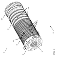
- FIG. 1 a three-dimensional perspective view of a portion of a turbomachine combustor (or simply, combustor) 2 is shown according to various embodiments.
- fuel is provided to a combustor cap section 4, at its inlet 6, via a fuel nozzle system (not shown) and initially mixed with air going through the cap section 4, as is known in the art. Then, the mixture ignites from a spark initiated in an igniter (not shown), as is known in the art.
- the flame is additionally mixed with air flowing through mixing holes 12 in order to assure that the fuel is properly burned. Also, the flame is transferred to adjacent combustors (obstructed in this view) through cross-fire holes 14, as is known in the art.
- the flame is diluted with air flowing through dilution holes 16 to properly mix the flame with air in the aft end 11 and cool the flame to reduce emissions.
- the aft end 11 of the combustor 2 includes an outlet 13 designed to connect with a transition piece, and ultimately, a turbomachine (both not shown).
- the inherent temperature and pressure conditions can cause material degradation including fatigue, cracking, erosion, etc., in various components in the combustor.
- this material degradation can affect the mixing and/or dilution apertures.
- methods are disclosed which help to reinforce those mixing and/or dilution apertures.
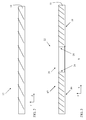
- FIG. 2 shows a schematic cross-sectional cut-away view of a surface 17 of the combustor 2 prior to forming of one or more of the apertures (e.g., mixing aperture 12, cross-fire aperture 14, etc.).
- Various embodiments include a preliminary step of forming one or more apertures (e.g., mixing aperture 12, cross-fire aperture 14, etc.), e.g., via punching, cutting, or otherwise puncturing the wall 18 of the combustor 18.
- FIG. 3 shows a schematic cross-sectional cut-away view of an inlet 20 of an aperture 22 formed according to the preliminary processes described herein. After formation of the aperture 22, the aperture 22 is referred to as an "existing" aperture herein.
- the existing aperture 22 can include, e.g., a mixing aperture 12 or a dilution aperture 16 as shown and described with reference to FIG. 1 .
- the existing aperture 22 has an initial profile 24, which can be substantially planar, e.g., perpendicular to a central axis A of the combustor. Additionally, the initial profile 24 can also be substantially planar along the outer surface 17 (radially outer surface) of the combustor's wall 18. That is, the initial profile 24 is substantially coplanar with the outer surface 17 of the combustor wall 18.
- FIGS. 4-5 illustrate the process of broaching (machining) the existing aperture 22 from FIG. 3 to modify the initial profile 24 (e.g., the substantially planar profile) and form a modified profile 32 ( FIG. 5 ).
- the modified profile 32 can also be smoothed, e.g., via conventional machining techniques such as sanding.
- the modified profile 32 is shown as smoothed in FIG. 5 .
- the modified profile 32 is substantially non-planar, and in some cases, has a greater surface area than the initial profile 24.
- the modified profile 32 includes a protruding interface (or protrusion) 60 extending radially outwardly from the radially outer surface 17 of the wall 18. That is, the modified profile 32 is substantially non-planar with the outer surface 17 of the wall 18.
- the modified profile 32 can include an arcuate interface 62 proximate the radially inner surface 19 of the wall 18, which increases the surface area of the inner surface (e.g., inner surface 19 and arcuate interface 62) relative to the inner surface of the initial profile 24.
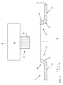
- the broaching process can include inserting a broaching tip 42 ( FIGS. 4-5 , 7 ) from a broaching member 44 into the existing aperture 22, and machining the initial profile 24 of the existing aperture 22 to form the modified profile 32.
- the broaching tip 42 includes a broaching surface 46 (indicated as having some texture).
- the broaching surface 46 includes at least one of a group of surfaces. This group of surfaces is shown in the illustrative broaching surface chart 50 in FIG. 6 , where broaching surface types A-K are shown in top and side views, respectively (top view shown above the side view for each broaching surface type). As shown, the broaching surface 46 of the broaching tip 42 ( FIGS.
- 2-3 can include at least one of: a square surface (type A), a round surface (type B), a single keyway surface (type C), a double keyway surface (type D), a 4-spline surface (type E), a hexagon surface (type F), a rectangular surface (type G), a double-cut surface (type H), an internal gear surface (type I), a round helical surface (type J) or a helical groove surface (type K).
- a combustor ring 36 which can be positioned adjacent to the inner diameter of the modified profile 32 (e.g., proximate the arcuate interface 62) and welded to the modified profile 32 according to various embodiments of the invention.
- the combustor ring 36 can be welded, e.g., via fillet welding, to the radially inner surface 19 along an outer diameter of the reinforcing ring and the inner diameter (radially inner surface 19) of the wall 17, in particular, along the modified profile 32.
- the weld 38 is shown between the combustor ring 36 and the modified profile 32 (contacting the arcuate interface 62 and the combustor ring 36.
- the modified profile 32 in particular, the greater surface area of the modified profile 32 as compared with the initial profile 24, enhances bonding between the combustor ring 36 and the wall 17 of the combustor 2 ( FIG. 1 )(after the fillet welding process is complete).
- the combustor ring 36 is inserted within the combustor 2 and welded to the wall 17, and then an opening corresponding with the aperture 22 is formed in the combustor ring 36, e.g., via cutting or machining the opening through the aperture 22 to expose the interior chamber 8 of the combustor 2.
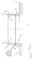
- FIG. 8 shows an alternative embodiment including a process of forming a weld collar 70 coupled to the modified profile 32, e.g., extending radailly outwardly from the modified profile 32.
- the weld collar 70 is formed as a 360 degree, 100 percent penetration weld over the protrusion (or, protruding interface) 60, which extends radially outwardly from the protrusion 60.
- the weld collar 70 can be formed after the modified profile 32 is formed, e.g., after the modified profile 32 has been smoothed.
- the weld collar 70 can be formed including a beveled or chamfered surface 72 along its inner diameter proximate its radially outermost point 74.
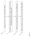
- FIG. 9 is a flow diagram illustrating processes that may be performed according to various embodiments of the invention. As shown, the processes can include:
- the modified profile formed according to various embodiments of the invention can have greater strength, and resistance to cracking, fatigue, etc. than the initial profile, and can provide for enhanced weld adhesion of a combustor ring.
Landscapes
- Engineering & Computer Science (AREA)
- Mechanical Engineering (AREA)
- Chemical & Material Sciences (AREA)
- Combustion & Propulsion (AREA)
- General Engineering & Computer Science (AREA)
- Structures Of Non-Positive Displacement Pumps (AREA)
Abstract
Description
- The subject matter disclosed herein relates to reinforced materials. More particularly, the subject matter relates to reinforced materials in combustor systems.
- Conventional combustors, such as turbomachine combustors, include a variety of apertures which aid the combustor in performing its designed functions. For example, combustors can include cross-fire apertures for enhancing firing, and mixing and dilution apertures for providing air to the combustion chamber.
- Due to the temperature and pressure conditions within combustors, these apertures are frequently reinforced. Conventionally, these apertures are reinforced using a reinforcing sleeve which is applied to the aperture and welded in place.
- The geometry of the reinforcing sleeve results in a high temperature gradient on the reinforcing sleeve during operation of the combustor, which can cause the sleeve to fail. Further, welding the sleeve effectively can be difficult due to limited access to the aperture.
- Various embodiments include methods of reinforcing apertures in turbomachine combustors, as well as related combustors. In various particular embodiments, a method of reinforcing an existing turbomachine combustor aperture includes: broaching the existing aperture in the turbomachine combustor to modify an initial profile of the existing aperture in the turbomachine combustor and form a modified profile, wherein the initial profile is substantially co-planar with an outer surface of the turbomachine combustor, and wherein the modified profile protrudes radially outward from the outer surface of the turbomachine combustor; and welding the existing aperture to a combustor ring, wherein the modified profile enhances bonding between the existing aperture and the combustor ring.
- A first aspect of the invention includes a method of reinforcing an existing turbomachine combustor aperture. This method can include: broaching the existing aperture in the turbomachine combustor to modify an initial profile of the existing aperture in the turbomachine combustor and form a modified profile, wherein the initial profile is substantially co-planar with an outer surface of the turbomachine combustor, and wherein the modified profile protrudes radially outward from the outer surface of the turbomachine combustor; and welding the existing aperture to a combustor ring, wherein the modified profile enhances bonding between the existing aperture and the combustor ring.
- A second aspect of the invention includes a method of reinforcing an existing turbomachine combustor aperture. The method can include: forming the aperture in a surface of the turbomachine combustor; broaching the aperture in the turbomachine combustor to modify an initial profile of the aperture in the turbomachine combustor and form a modified profile, wherein the broaching includes: inserting a broaching tip having a broaching surface into the existing aperture; and machining the initial profile of the existing aperture to form the modified profile, wherein the modified profile includes a greater surface area than the initial profile; and machining the modified profile to form a smooth, modified profile.
- A third aspect of the invention includes a turbomachine combustor including: a wall having: a radially inner surface and a radially outer surface; and an aperture extending between the radially inner surface and the radially outer surface, the aperture including one of a mixing aperture or a dilution aperture, the aperture having: an arcuate interface proximate the radially inner surface; and a protruding interface extending radially outward from the radially outer surface; and a combustor ring fillet welded to the wall at the aperture along the arcuate interface.
- These and other features of this invention will be more readily understood from the following detailed description of the various aspects of the invention taken in conjunction with the accompanying drawings that depict various embodiments of the invention, in which:
-
FIG. 1 shows a three-dimensional perspective view of a portion of a turbomachine combustor according to various embodiments of the invention. -
FIGS. 2-3 show a cut-away cross-sectional view of processes in forming a turbomachine combustor aperture according to various embodiments of the invention. -
FIG. 4 shows a cut-away cross-sectional view of the turbomachine combustor aperture ofFIG. 3 undergoing processes according to various embodiments of the invention. -
FIG. 5 shows a cut-away cross-sectional view of the turbomachine combustor aperture ofFIG. 4 undergoing processes according to various embodiments of the invention -
FIG. 6 shows a schematic depiction of broaching device tips which can be utilized in methods according to various embodiments of the invention. -
FIG. 7 shows an alternative process of forming a turbomachine combustor aperture according to various embodiments of the invention. -
FIG. 8 shows an alternative embodiment of forming a turbomachine combustor aperture according to various embodiments of the invention. -
FIG. 9 is a flow diagram depicting processes according to various embodiments of the invention. - It is noted that the drawings of the invention are not necessarily to scale. The drawings are intended to depict only typical aspects of the invention, and therefore should not be considered as limiting the scope of the invention. In the drawings, like numbering represents like elements between the drawings.
- As noted, the subject matter disclosed herein relates to reinforced materials. More particularly, the subject matter relates to reinforced materials in combustor systems.
- As described herein, due to the temperature and pressure conditions within combustors, these apertures are frequently reinforced. Conventionally, these apertures are reinforced using a reinforcing sleeve which is applied to the aperture and welded in place.
- The geometry of the sleeve results in a high temperature gradient on the sleeve during operation of the combustor, which can cause the reinforcing sleeve to fail. Further, welding the sleeve effectively can be difficult due to limited access to the aperture.
- In contrast to conventional approaches, various embodiments include methods of reinforcing combustor apertures via broaching to form eyelets. In particular, various embodiments of the invention include reinforcing the edges of a mixing aperture or dilution aperture in a turbomachine combustor by forming eyelets within those apertures.
- In particular embodiments, the method can include reinforcing an existing turbomachine combustor aperture by: broaching the existing aperture to modify a profile of the existing aperture and form a modified profile; and fillet welding a combustor ring to the modified profile to bond the combustor ring to the aperture.
- Various particular embodiments of the invention include a method of reinforcing an aperture in a turbomachine combustor. This method can include: forming the aperture in a surface of the turbomachine combustor; broaching the aperture to modify an initial profile of the aperture and form a modified profile; and machining an inner diameter of the modified profile to smooth the modified profile (e.g., to remove one or more burrs).
- Various particular embodiments of the invention include a method of reinforcing an existing turbomachine combustor aperture. This method can include: broaching the existing aperture in the turbomachine combustor to modify an initial profile of the existing aperture in the turbomachine combustor and form a modified profile, wherein the initial profile is substantially co-planar with an outer surface of the turbomachine combustor, and wherein the modified profile protrudes radially outwardly from the outer surface of the turbomachine combustor; and fillet welding the existing aperture to a combustor ring, wherein the modified profile enhances bonding between the existing aperture and the combustor ring.
- Various other embodiments of the invention include a method of reinforcing an existing turbomachine combustor aperture. The method can include: forming the aperture in a surface of the turbomachine combustor; broaching the aperture in the turbomachine combustor to modify an initial profile of the aperture in the turbomachine combustor and form a modified profile, wherein the broaching includes: inserting a broaching tip having a broaching surface into the existing aperture; and machining the initial profile of the existing aperture to form the modified profile, wherein the modified profile includes a greater surface area than the initial profile; and machining the modified profile to form a smooth, modified profile.
- Various additional embodiments of the invention include a turbomachine combustor including: a wall having: a radially inner surface and a radially outer surface; and an aperture extending between the radially inner surface and the radially outer surface, the aperture including one of a mixing aperture or a dilution aperture, the aperture having: an arcuate interface proximate the radially inner surface; and a protruding interface extending radially outward from the radially outer surface; and a combustor ring fillet welded to the wall at the aperture along the arcuate interface.
- As used herein, the terms "axial" and/or "axially" refer to the relative position/direction of objects along axis A, which is substantially perpendicular to the axis of rotation of the turbomachine (in particular, the rotor section). As further used herein, the terms "radial" and/or "radially" refer to the relative position/direction of objects along axis (r), which is substantially perpendicular with axis A and intersects axis A at only one location. Additionally, the terms "circumferential" and/or "circumferentially" refer to the relative position/direction of objects along a circumference (C) which surrounds axis A but does not intersect the axis A at any location.
- Turning to
FIG. 1 , a three-dimensional perspective view of a portion of a turbomachine combustor (or simply, combustor) 2 is shown according to various embodiments. As shown, fuel is provided to acombustor cap section 4, at itsinlet 6, via a fuel nozzle system (not shown) and initially mixed with air going through thecap section 4, as is known in the art. Then, the mixture ignites from a spark initiated in an igniter (not shown), as is known in the art. In theprimary flame zone 10, the flame is additionally mixed with air flowing through mixingholes 12 in order to assure that the fuel is properly burned. Also, the flame is transferred to adjacent combustors (obstructed in this view) throughcross-fire holes 14, as is known in the art. At theaft end 11 of thecombustor 2, the flame is diluted with air flowing throughdilution holes 16 to properly mix the flame with air in theaft end 11 and cool the flame to reduce emissions. Theaft end 11 of thecombustor 2 includes anoutlet 13 designed to connect with a transition piece, and ultimately, a turbomachine (both not shown). - As described herein, during operation of a conventional turbomachine combustor, the inherent temperature and pressure conditions can cause material degradation including fatigue, cracking, erosion, etc., in various components in the combustor. In particular, this material degradation can affect the mixing and/or dilution apertures. According to various embodiments, methods are disclosed which help to reinforce those mixing and/or dilution apertures.
-
FIG. 2 shows a schematic cross-sectional cut-away view of asurface 17 of thecombustor 2 prior to forming of one or more of the apertures (e.g., mixingaperture 12,cross-fire aperture 14, etc.). Various embodiments include a preliminary step of forming one or more apertures (e.g., mixingaperture 12,cross-fire aperture 14, etc.), e.g., via punching, cutting, or otherwise puncturing thewall 18 of thecombustor 18.FIG. 3 shows a schematic cross-sectional cut-away view of aninlet 20 of anaperture 22 formed according to the preliminary processes described herein. After formation of theaperture 22, theaperture 22 is referred to as an "existing" aperture herein. - The existing
aperture 22, can include, e.g., a mixingaperture 12 or adilution aperture 16 as shown and described with reference toFIG. 1 . As shown, the existingaperture 22 has aninitial profile 24, which can be substantially planar, e.g., perpendicular to a central axis A of the combustor. Additionally, theinitial profile 24 can also be substantially planar along the outer surface 17 (radially outer surface) of the combustor'swall 18. That is, theinitial profile 24 is substantially coplanar with theouter surface 17 of thecombustor wall 18. -
FIGS. 4-5 illustrate the process of broaching (machining) the existingaperture 22 fromFIG. 3 to modify the initial profile 24 (e.g., the substantially planar profile) and form a modified profile 32 (FIG. 5 ). According to various embodiments, the modifiedprofile 32 can also be smoothed, e.g., via conventional machining techniques such as sanding. The modifiedprofile 32 is shown as smoothed inFIG. 5 . The modifiedprofile 32 is substantially non-planar, and in some cases, has a greater surface area than theinitial profile 24. - In various embodiments, the modified
profile 32 includes a protruding interface (or protrusion) 60 extending radially outwardly from the radiallyouter surface 17 of thewall 18. That is, the modifiedprofile 32 is substantially non-planar with theouter surface 17 of thewall 18. The modifiedprofile 32 can include anarcuate interface 62 proximate the radiallyinner surface 19 of thewall 18, which increases the surface area of the inner surface (e.g.,inner surface 19 and arcuate interface 62) relative to the inner surface of theinitial profile 24. - In various embodiments, the broaching process can include inserting a broaching tip 42 (
FIGS. 4-5 ,7 ) from a broachingmember 44 into the existingaperture 22, and machining theinitial profile 24 of the existingaperture 22 to form the modifiedprofile 32. In various cases, the broachingtip 42 includes a broaching surface 46 (indicated as having some texture). In some cases, the broachingsurface 46 includes at least one of a group of surfaces. This group of surfaces is shown in the illustrativebroaching surface chart 50 inFIG. 6 , where broaching surface types A-K are shown in top and side views, respectively (top view shown above the side view for each broaching surface type). As shown, the broachingsurface 46 of the broaching tip 42 (FIGS. 2-3 ) can include at least one of: a square surface (type A), a round surface (type B), a single keyway surface (type C), a double keyway surface (type D), a 4-spline surface (type E), a hexagon surface (type F), a rectangular surface (type G), a double-cut surface (type H), an internal gear surface (type I), a round helical surface (type J) or a helical groove surface (type K). - According to another aspect of the invention, shown in
FIG. 7 is acombustor ring 36 which can be positioned adjacent to the inner diameter of the modified profile 32 (e.g., proximate the arcuate interface 62) and welded to the modifiedprofile 32 according to various embodiments of the invention. Thecombustor ring 36 can be welded, e.g., via fillet welding, to the radiallyinner surface 19 along an outer diameter of the reinforcing ring and the inner diameter (radially inner surface 19) of thewall 17, in particular, along the modifiedprofile 32. Theweld 38 is shown between thecombustor ring 36 and the modified profile 32 (contacting thearcuate interface 62 and thecombustor ring 36. The modifiedprofile 32, in particular, the greater surface area of the modifiedprofile 32 as compared with theinitial profile 24, enhances bonding between thecombustor ring 36 and thewall 17 of the combustor 2 (FIG. 1 )(after the fillet welding process is complete). In some cases, thecombustor ring 36 is inserted within thecombustor 2 and welded to thewall 17, and then an opening corresponding with theaperture 22 is formed in thecombustor ring 36, e.g., via cutting or machining the opening through theaperture 22 to expose theinterior chamber 8 of thecombustor 2. -
FIG. 8 shows an alternative embodiment including a process of forming aweld collar 70 coupled to the modifiedprofile 32, e.g., extending radailly outwardly from the modifiedprofile 32. In particular, theweld collar 70 is formed as a 360 degree, 100 percent penetration weld over the protrusion (or, protruding interface) 60, which extends radially outwardly from theprotrusion 60. Theweld collar 70 can be formed after the modifiedprofile 32 is formed, e.g., after the modifiedprofile 32 has been smoothed. In some cases, theweld collar 70 can be formed including a beveled or chamferedsurface 72 along its inner diameter proximate its radiallyoutermost point 74. -
FIG. 9 is a flow diagram illustrating processes that may be performed according to various embodiments of the invention. As shown, the processes can include: - Process P0 (Preliminary optional process): Forming an aperture in a wall of a turbomachine combustor;
- Process P1: Broaching the existing aperture in the turbomachine combustor to modify an initial profile of the existing aperture and form a modified profile;
- Process P2: Machining the modified profile to form a smooth, modified profile; and
- Process P3: Welding a combustor ring along an inner surface of the modified profile. In various embodiments, the welding can include fillet welding. As is known in the art, a fillet welt is used to join two pieces of material at approximately a 90 degree angle, e.g., where the materials diverge from one another.
- As described herein, the modified profile formed according to various embodiments of the invention can have greater strength, and resistance to cracking, fatigue, etc. than the initial profile, and can provide for enhanced weld adhesion of a combustor ring.
- The terminology used herein is for the purpose of describing particular embodiments only and is not intended to be limiting of the disclosure. As used herein, the singular forms "a", "an" and "the" are intended to include the plural forms as well, unless the context clearly indicates otherwise. It will be further understood that the terms "comprises" and/or "comprising," when used in this specification, specify the presence of stated features, integers, steps, operations, elements, and/or components, but do not preclude the presence or addition of one or more other features, integers, steps, operations, elements, components, and/or groups thereof. It is further understood that the terms "front" and "back" are not intended to be limiting and are intended to be interchangeable where appropriate.
- This written description uses examples to disclose the invention, including the best mode, and also to enable any person skilled in the art to practice the invention, including making and using any devices or systems and performing any incorporated methods. The patentable scope of the invention is defined by the claims, and may include other examples that occur to those skilled in the art. Such other examples are intended to be within the scope of the claims if they have structural elements that do not differ from the literal language of the claims, or if they include equivalent structural elements with insubstantial differences from the literal languages of the claims.
Claims (12)
- A method of reinforcing an existing turbomachine combustor aperture (22), the method comprising:broaching the existing aperture (22) in the turbomachine combustor (2) to modify an initial profile (24) of the existing aperture (22) in the turbomachine combustor (2) and form a modified profile (32),wherein the initial profile (24) is substantially co-planar with an outer surface (17) of the turbomachine combustor (2), and wherein the modified profile (32) protrudes radially outwardly from the outer surface (17) of the turbomachine combustor (2); andwelding the existing aperture (22) to a combustor ring (36), wherein the modified profile (32) enhances bonding between the existing aperture (22) and the combustor ring (36).
- The method of claim 1, wherein the existing turbomachine combustor aperture (22) includes a mixing aperture for allowing mixing of a combustion gas and air.
- The method of claim 1, wherein the existing turbomachine combustor aperture (22) includes a dilution aperture for diluting a combustion mixture after a combustion process.
- The method of any of claims 1 to 3, wherein the broaching includes:inserting a broaching tip (42) into the existing aperture (22); andmachining the initial profile (24) of the existing aperture (22) to form the modified profile (32).
- The method of claim 4, wherein the broaching tip (42) includes a broaching surface (46).
- The method of claim 5, wherein the broaching surface (46) includes at least one of a square surface, a round surface, a single keyway surface, a double keyway surface, a 4-spline surface, a hexagon surface, a rectangular surface, a double-cut surface, an internal gear surface, a round helical surface or a helical groove surface.
- The method of any of claims 1 to 6, wherein the modified profile (32) includes a greater surface area than the initial profile (24).
- The method of any of claims 1 to 7, further comprising machining the modified profile (32) to form a smooth, modified profile (32) prior to the welding.
- The method of any of claims 1 to 8, wherein the welding includes fillet welding.
- The method of any preceding claim, further comprising forming a welded collar (70) coupled to the weld and extending radially outwardly from the weld.
- A turbomachine combustor comprising:a wall (18) having:a radially inner surface (19) and a radially outer surface (17); andan aperture (22) extending between the radially inner surface (19) and the radially outer surface (17), the aperture (22) including one of a mixing aperture or a dilution aperture, the aperture (22) having:an arcuate interface (62) proximate the radially inner surface (19); anda protruding interface (60) extending radially outward from the radially outer surface (17); anda combustor ring (36) fillet welded to the wall (18) at the aperture (22) along the arcuate interface (62).
- The turbomachine combustor of claim 11, further comprising a welded collar (70) coupled to the protruding interface (60) and extending radially outward from the radially outer surface (17).
Priority Applications (1)
| Application Number | Priority Date | Filing Date | Title |
|---|---|---|---|
| PL13198770T PL2749375T3 (en) | 2012-12-28 | 2013-12-20 | Method of reinforcing combustor aperture and related combustor |
Applications Claiming Priority (1)
| Application Number | Priority Date | Filing Date | Title |
|---|---|---|---|
| PCT/PL2012/000133 WO2014104901A1 (en) | 2012-12-28 | 2012-12-28 | Methods of reinforcing combustor aperture and related combustor |
Publications (2)
| Publication Number | Publication Date |
|---|---|
| EP2749375A1 true EP2749375A1 (en) | 2014-07-02 |
| EP2749375B1 EP2749375B1 (en) | 2015-10-07 |
Family
ID=47683997
Family Applications (1)
| Application Number | Title | Priority Date | Filing Date |
|---|---|---|---|
| EP13198770.3A Active EP2749375B1 (en) | 2012-12-28 | 2013-12-20 | Method of reinforcing combustor aperture and related combustor |
Country Status (5)
| Country | Link |
|---|---|
| US (1) | US9377199B2 (en) |
| EP (1) | EP2749375B1 (en) |
| JP (1) | JP6283220B2 (en) |
| PL (1) | PL2749375T3 (en) |
| WO (1) | WO2014104901A1 (en) |
Families Citing this family (2)
| Publication number | Priority date | Publication date | Assignee | Title |
|---|---|---|---|---|
| CA2963495C (en) * | 2014-10-01 | 2021-10-26 | Ge Oil & Gas Esp, Inc. | Dual plate motor support for horizontal pumping system |
| US12007113B2 (en) | 2021-04-20 | 2024-06-11 | Ge Infrastructure Technology Llc | Gas turbine component with fluid intake hole free of angled surface transitions |
Citations (4)
| Publication number | Priority date | Publication date | Assignee | Title |
|---|---|---|---|---|
| JPS60194234A (en) * | 1984-03-16 | 1985-10-02 | Hitachi Ltd | gas turbine combustor |
| US5209067A (en) * | 1990-10-17 | 1993-05-11 | Societe Nationale D'etude Et De Construction De Moteurs D'aviation S.N.E.C.M.A. | Gas turbine combustion chamber wall structure for minimizing cooling film disturbances |
| US20070227149A1 (en) * | 2006-03-30 | 2007-10-04 | Snecma | Configuration of dilution openings in a turbomachine combustion chamber wall |
| US20120036859A1 (en) * | 2010-08-12 | 2012-02-16 | General Electric Company | Combustor transition piece with dilution sleeves and related method |
Family Cites Families (9)
| Publication number | Priority date | Publication date | Assignee | Title |
|---|---|---|---|---|
| US1958705A (en) * | 1930-03-15 | 1934-05-15 | Snap On Tools Inc | Apparatus for thin wall broaching |
| DE1301644B (en) * | 1965-11-23 | 1969-08-21 | Daimler Benz Ag | Device for ventilating injection nozzles for gas turbine engines, especially aircraft engines |
| JPS5143294Y2 (en) | 1972-05-16 | 1976-10-21 | ||
| JPS5124937A (en) * | 1974-08-27 | 1976-02-28 | Mitsubishi Heavy Ind Ltd | NENRYONEN SHOSOCHI |
| JPH10184916A (en) | 1996-12-20 | 1998-07-14 | Nippon Gasket Co Ltd | Metallic gasket |
| US8347854B2 (en) | 2007-06-19 | 2013-01-08 | Flexible Ceramics, Inc | Internal combustion (IC) engine head assembly combustion chamber multiple spark ignition (MSI) fuel savings device and methods of fabrication thereof |
| EP2042724A1 (en) | 2007-09-26 | 2009-04-01 | Magneti Marelli Powertrain S.p.A. | Intake manifold for an internal combustion engine provided with metallic reinforcement brackets for fastening the fuel common rail |
| US8448443B2 (en) * | 2007-10-11 | 2013-05-28 | General Electric Company | Combustion liner thimble insert and related method |
| FR2925147B1 (en) * | 2007-12-14 | 2012-07-13 | Snecma | DEVICE FOR GUIDING AN ELEMENT IN AN ORIFICE OF A TURBOMACHINE COMBUSTION CHAMBER WALL |
-
2012
- 2012-12-28 WO PCT/PL2012/000133 patent/WO2014104901A1/en not_active Ceased
- 2012-12-28 US US14/124,874 patent/US9377199B2/en active Active
-
2013
- 2013-12-20 EP EP13198770.3A patent/EP2749375B1/en active Active
- 2013-12-20 PL PL13198770T patent/PL2749375T3/en unknown
- 2013-12-26 JP JP2013268251A patent/JP6283220B2/en active Active
Patent Citations (4)
| Publication number | Priority date | Publication date | Assignee | Title |
|---|---|---|---|---|
| JPS60194234A (en) * | 1984-03-16 | 1985-10-02 | Hitachi Ltd | gas turbine combustor |
| US5209067A (en) * | 1990-10-17 | 1993-05-11 | Societe Nationale D'etude Et De Construction De Moteurs D'aviation S.N.E.C.M.A. | Gas turbine combustion chamber wall structure for minimizing cooling film disturbances |
| US20070227149A1 (en) * | 2006-03-30 | 2007-10-04 | Snecma | Configuration of dilution openings in a turbomachine combustion chamber wall |
| US20120036859A1 (en) * | 2010-08-12 | 2012-02-16 | General Electric Company | Combustor transition piece with dilution sleeves and related method |
Also Published As
| Publication number | Publication date |
|---|---|
| US20150292740A1 (en) | 2015-10-15 |
| PL2749375T3 (en) | 2016-08-31 |
| JP6283220B2 (en) | 2018-02-21 |
| WO2014104901A1 (en) | 2014-07-03 |
| EP2749375B1 (en) | 2015-10-07 |
| JP2014149146A (en) | 2014-08-21 |
| US9377199B2 (en) | 2016-06-28 |
Similar Documents
| Publication | Publication Date | Title |
|---|---|---|
| US6434821B1 (en) | Method of making a combustion chamber liner | |
| EP1174209B1 (en) | Method of repairing combustion chamber liners | |
| EP2957833B1 (en) | Combustor assembly with chutes | |
| US9523286B2 (en) | Vane segment and axial-flow fluid machine including the same | |
| JP5149596B2 (en) | Combustor dome mixer holding means | |
| US10450896B2 (en) | Manufacture of a casing with a boss | |
| EP3377819B1 (en) | Method for reconditioning fuel nozzle assemblies | |
| EP2657606A2 (en) | A combustor and a method for repairing the combustor | |
| EP3366412A1 (en) | A workpiece with a spatial weld joint plane arrangement and a method for forming the workpiece | |
| US9377199B2 (en) | Methods of reinforcing combustor aperture and related combustor | |
| CN106471312B (en) | Assemblies for turbine engine combustion chambers including bosses and annular elements | |
| JP4749313B2 (en) | Combustor dome repair method | |
| CN106068171B (en) | Weld head fastening systems | |
| EP1782913A2 (en) | Integral backing ring for stub shaft weld repairs of rotating equipment and related method | |
| US7507933B2 (en) | Method for fabricating a rotor shaft | |
| US9657899B2 (en) | Replacement oil cartridge tip and method | |
| CN103216335B (en) | Process of fabricating a fuel nozzel assembly | |
| EP1457737B1 (en) | Gas turbine engine combustor | |
| JP6880577B2 (en) | Ceramic mounting method and burner structure | |
| KR20140145083A (en) | Method for producing a built hollow valve | |
| US10490981B1 (en) | Spark plug for an internal combustion engine with reduced risk of center electrode detachment | |
| US20140271171A1 (en) | Compressor airfoil | |
| EP2674678A2 (en) | Method of manufacturing an impingement sleeve for a turbine engine combustor | |
| US9757837B2 (en) | Machining tool including a pivoting machining arm | |
| EP2532966A2 (en) | Combustion nozzle and method for modifying the combustor nozzle |
Legal Events
| Date | Code | Title | Description |
|---|---|---|---|
| 17P | Request for examination filed |
Effective date: 20131220 |
|
| AK | Designated contracting states |
Kind code of ref document: A1 Designated state(s): AL AT BE BG CH CY CZ DE DK EE ES FI FR GB GR HR HU IE IS IT LI LT LU LV MC MK MT NL NO PL PT RO RS SE SI SK SM TR |
|
| AX | Request for extension of the european patent |
Extension state: BA ME |
|
| PUAI | Public reference made under article 153(3) epc to a published international application that has entered the european phase |
Free format text: ORIGINAL CODE: 0009012 |
|
| R17P | Request for examination filed (corrected) |
Effective date: 20150105 |
|
| RBV | Designated contracting states (corrected) |
Designated state(s): AL AT BE BG CH CY CZ DE DK EE ES FI FR GB GR HR HU IE IS IT LI LT LU LV MC MK MT NL NO PL PT RO RS SE SI SK SM TR |
|
| GRAP | Despatch of communication of intention to grant a patent |
Free format text: ORIGINAL CODE: EPIDOSNIGR1 |
|
| INTG | Intention to grant announced |
Effective date: 20150529 |
|
| GRAS | Grant fee paid |
Free format text: ORIGINAL CODE: EPIDOSNIGR3 |
|
| GRAA | (expected) grant |
Free format text: ORIGINAL CODE: 0009210 |
|
| AK | Designated contracting states |
Kind code of ref document: B1 Designated state(s): AL AT BE BG CH CY CZ DE DK EE ES FI FR GB GR HR HU IE IS IT LI LT LU LV MC MK MT NL NO PL PT RO RS SE SI SK SM TR |
|
| REG | Reference to a national code |
Ref country code: GB Ref legal event code: FG4D |
|
| REG | Reference to a national code |
Ref country code: AT Ref legal event code: REF Ref document number: 753436 Country of ref document: AT Kind code of ref document: T Effective date: 20151015 Ref country code: CH Ref legal event code: EP |
|
| REG | Reference to a national code |
Ref country code: IE Ref legal event code: FG4D |
|
| REG | Reference to a national code |
Ref country code: DE Ref legal event code: R096 Ref document number: 602013003367 Country of ref document: DE |
|
| REG | Reference to a national code |
Ref country code: NL Ref legal event code: MP Effective date: 20151007 |
|
| REG | Reference to a national code |
Ref country code: AT Ref legal event code: MK05 Ref document number: 753436 Country of ref document: AT Kind code of ref document: T Effective date: 20151007 |
|
| REG | Reference to a national code |
Ref country code: LT Ref legal event code: MG4D |
|
| PG25 | Lapsed in a contracting state [announced via postgrant information from national office to epo] |
Ref country code: IS Free format text: LAPSE BECAUSE OF FAILURE TO SUBMIT A TRANSLATION OF THE DESCRIPTION OR TO PAY THE FEE WITHIN THE PRESCRIBED TIME-LIMIT Effective date: 20160207 Ref country code: HR Free format text: LAPSE BECAUSE OF FAILURE TO SUBMIT A TRANSLATION OF THE DESCRIPTION OR TO PAY THE FEE WITHIN THE PRESCRIBED TIME-LIMIT Effective date: 20151007 Ref country code: IT Free format text: LAPSE BECAUSE OF FAILURE TO SUBMIT A TRANSLATION OF THE DESCRIPTION OR TO PAY THE FEE WITHIN THE PRESCRIBED TIME-LIMIT Effective date: 20151007 Ref country code: ES Free format text: LAPSE BECAUSE OF FAILURE TO SUBMIT A TRANSLATION OF THE DESCRIPTION OR TO PAY THE FEE WITHIN THE PRESCRIBED TIME-LIMIT Effective date: 20151007 Ref country code: NO Free format text: LAPSE BECAUSE OF FAILURE TO SUBMIT A TRANSLATION OF THE DESCRIPTION OR TO PAY THE FEE WITHIN THE PRESCRIBED TIME-LIMIT Effective date: 20160107 Ref country code: LT Free format text: LAPSE BECAUSE OF FAILURE TO SUBMIT A TRANSLATION OF THE DESCRIPTION OR TO PAY THE FEE WITHIN THE PRESCRIBED TIME-LIMIT Effective date: 20151007 Ref country code: NL Free format text: LAPSE BECAUSE OF FAILURE TO SUBMIT A TRANSLATION OF THE DESCRIPTION OR TO PAY THE FEE WITHIN THE PRESCRIBED TIME-LIMIT Effective date: 20151007 |
|
| PG25 | Lapsed in a contracting state [announced via postgrant information from national office to epo] |
Ref country code: GR Free format text: LAPSE BECAUSE OF FAILURE TO SUBMIT A TRANSLATION OF THE DESCRIPTION OR TO PAY THE FEE WITHIN THE PRESCRIBED TIME-LIMIT Effective date: 20160108 Ref country code: RS Free format text: LAPSE BECAUSE OF FAILURE TO SUBMIT A TRANSLATION OF THE DESCRIPTION OR TO PAY THE FEE WITHIN THE PRESCRIBED TIME-LIMIT Effective date: 20151007 Ref country code: LV Free format text: LAPSE BECAUSE OF FAILURE TO SUBMIT A TRANSLATION OF THE DESCRIPTION OR TO PAY THE FEE WITHIN THE PRESCRIBED TIME-LIMIT Effective date: 20151007 Ref country code: FI Free format text: LAPSE BECAUSE OF FAILURE TO SUBMIT A TRANSLATION OF THE DESCRIPTION OR TO PAY THE FEE WITHIN THE PRESCRIBED TIME-LIMIT Effective date: 20151007 Ref country code: PT Free format text: LAPSE BECAUSE OF FAILURE TO SUBMIT A TRANSLATION OF THE DESCRIPTION OR TO PAY THE FEE WITHIN THE PRESCRIBED TIME-LIMIT Effective date: 20160208 Ref country code: AT Free format text: LAPSE BECAUSE OF FAILURE TO SUBMIT A TRANSLATION OF THE DESCRIPTION OR TO PAY THE FEE WITHIN THE PRESCRIBED TIME-LIMIT Effective date: 20151007 Ref country code: SE Free format text: LAPSE BECAUSE OF FAILURE TO SUBMIT A TRANSLATION OF THE DESCRIPTION OR TO PAY THE FEE WITHIN THE PRESCRIBED TIME-LIMIT Effective date: 20151007 Ref country code: BE Free format text: LAPSE BECAUSE OF NON-PAYMENT OF DUE FEES Effective date: 20151231 |
|
| REG | Reference to a national code |
Ref country code: DE Ref legal event code: R097 Ref document number: 602013003367 Country of ref document: DE |
|
| PG25 | Lapsed in a contracting state [announced via postgrant information from national office to epo] |
Ref country code: MC Free format text: LAPSE BECAUSE OF FAILURE TO SUBMIT A TRANSLATION OF THE DESCRIPTION OR TO PAY THE FEE WITHIN THE PRESCRIBED TIME-LIMIT Effective date: 20151007 Ref country code: CZ Free format text: LAPSE BECAUSE OF FAILURE TO SUBMIT A TRANSLATION OF THE DESCRIPTION OR TO PAY THE FEE WITHIN THE PRESCRIBED TIME-LIMIT Effective date: 20151007 Ref country code: LU Free format text: LAPSE BECAUSE OF FAILURE TO SUBMIT A TRANSLATION OF THE DESCRIPTION OR TO PAY THE FEE WITHIN THE PRESCRIBED TIME-LIMIT Effective date: 20151220 |
|
| PLBE | No opposition filed within time limit |
Free format text: ORIGINAL CODE: 0009261 |
|
| STAA | Information on the status of an ep patent application or granted ep patent |
Free format text: STATUS: NO OPPOSITION FILED WITHIN TIME LIMIT |
|
| PG25 | Lapsed in a contracting state [announced via postgrant information from national office to epo] |
Ref country code: SK Free format text: LAPSE BECAUSE OF FAILURE TO SUBMIT A TRANSLATION OF THE DESCRIPTION OR TO PAY THE FEE WITHIN THE PRESCRIBED TIME-LIMIT Effective date: 20151007 Ref country code: DK Free format text: LAPSE BECAUSE OF FAILURE TO SUBMIT A TRANSLATION OF THE DESCRIPTION OR TO PAY THE FEE WITHIN THE PRESCRIBED TIME-LIMIT Effective date: 20151007 Ref country code: EE Free format text: LAPSE BECAUSE OF FAILURE TO SUBMIT A TRANSLATION OF THE DESCRIPTION OR TO PAY THE FEE WITHIN THE PRESCRIBED TIME-LIMIT Effective date: 20151007 Ref country code: RO Free format text: LAPSE BECAUSE OF FAILURE TO SUBMIT A TRANSLATION OF THE DESCRIPTION OR TO PAY THE FEE WITHIN THE PRESCRIBED TIME-LIMIT Effective date: 20151007 Ref country code: SM Free format text: LAPSE BECAUSE OF FAILURE TO SUBMIT A TRANSLATION OF THE DESCRIPTION OR TO PAY THE FEE WITHIN THE PRESCRIBED TIME-LIMIT Effective date: 20151007 |
|
| 26N | No opposition filed |
Effective date: 20160708 |
|
| REG | Reference to a national code |
Ref country code: IE Ref legal event code: MM4A |
|
| REG | Reference to a national code |
Ref country code: FR Ref legal event code: ST Effective date: 20160831 |
|
| PG25 | Lapsed in a contracting state [announced via postgrant information from national office to epo] |
Ref country code: IE Free format text: LAPSE BECAUSE OF NON-PAYMENT OF DUE FEES Effective date: 20151220 |
|
| PG25 | Lapsed in a contracting state [announced via postgrant information from national office to epo] |
Ref country code: FR Free format text: LAPSE BECAUSE OF NON-PAYMENT OF DUE FEES Effective date: 20151231 Ref country code: SI Free format text: LAPSE BECAUSE OF FAILURE TO SUBMIT A TRANSLATION OF THE DESCRIPTION OR TO PAY THE FEE WITHIN THE PRESCRIBED TIME-LIMIT Effective date: 20151007 |
|
| PG25 | Lapsed in a contracting state [announced via postgrant information from national office to epo] |
Ref country code: BE Free format text: LAPSE BECAUSE OF FAILURE TO SUBMIT A TRANSLATION OF THE DESCRIPTION OR TO PAY THE FEE WITHIN THE PRESCRIBED TIME-LIMIT Effective date: 20151007 |
|
| PG25 | Lapsed in a contracting state [announced via postgrant information from national office to epo] |
Ref country code: HU Free format text: LAPSE BECAUSE OF FAILURE TO SUBMIT A TRANSLATION OF THE DESCRIPTION OR TO PAY THE FEE WITHIN THE PRESCRIBED TIME-LIMIT; INVALID AB INITIO Effective date: 20131220 Ref country code: BG Free format text: LAPSE BECAUSE OF FAILURE TO SUBMIT A TRANSLATION OF THE DESCRIPTION OR TO PAY THE FEE WITHIN THE PRESCRIBED TIME-LIMIT Effective date: 20151007 |
|
| PG25 | Lapsed in a contracting state [announced via postgrant information from national office to epo] |
Ref country code: CY Free format text: LAPSE BECAUSE OF FAILURE TO SUBMIT A TRANSLATION OF THE DESCRIPTION OR TO PAY THE FEE WITHIN THE PRESCRIBED TIME-LIMIT Effective date: 20151007 |
|
| REG | Reference to a national code |
Ref country code: CH Ref legal event code: PL |
|
| PG25 | Lapsed in a contracting state [announced via postgrant information from national office to epo] |
Ref country code: MT Free format text: LAPSE BECAUSE OF FAILURE TO SUBMIT A TRANSLATION OF THE DESCRIPTION OR TO PAY THE FEE WITHIN THE PRESCRIBED TIME-LIMIT Effective date: 20151007 |
|
| PG25 | Lapsed in a contracting state [announced via postgrant information from national office to epo] |
Ref country code: LI Free format text: LAPSE BECAUSE OF NON-PAYMENT OF DUE FEES Effective date: 20161231 Ref country code: CH Free format text: LAPSE BECAUSE OF NON-PAYMENT OF DUE FEES Effective date: 20161231 |
|
| PG25 | Lapsed in a contracting state [announced via postgrant information from national office to epo] |
Ref country code: MK Free format text: LAPSE BECAUSE OF FAILURE TO SUBMIT A TRANSLATION OF THE DESCRIPTION OR TO PAY THE FEE WITHIN THE PRESCRIBED TIME-LIMIT Effective date: 20151007 |
|
| GBPC | Gb: european patent ceased through non-payment of renewal fee |
Effective date: 20171220 |
|
| PG25 | Lapsed in a contracting state [announced via postgrant information from national office to epo] |
Ref country code: AL Free format text: LAPSE BECAUSE OF FAILURE TO SUBMIT A TRANSLATION OF THE DESCRIPTION OR TO PAY THE FEE WITHIN THE PRESCRIBED TIME-LIMIT Effective date: 20151007 Ref country code: TR Free format text: LAPSE BECAUSE OF FAILURE TO SUBMIT A TRANSLATION OF THE DESCRIPTION OR TO PAY THE FEE WITHIN THE PRESCRIBED TIME-LIMIT Effective date: 20151007 |
|
| PG25 | Lapsed in a contracting state [announced via postgrant information from national office to epo] |
Ref country code: GB Free format text: LAPSE BECAUSE OF NON-PAYMENT OF DUE FEES Effective date: 20171220 |
|
| PGFP | Annual fee paid to national office [announced via postgrant information from national office to epo] |
Ref country code: PL Payment date: 20191122 Year of fee payment: 7 |
|
| PG25 | Lapsed in a contracting state [announced via postgrant information from national office to epo] |
Ref country code: PL Free format text: LAPSE BECAUSE OF NON-PAYMENT OF DUE FEES Effective date: 20201220 |
|
| REG | Reference to a national code |
Ref country code: DE Ref legal event code: R081 Ref document number: 602013003367 Country of ref document: DE Owner name: GENERAL ELECTRIC TECHNOLOGY GMBH, CH Free format text: FORMER OWNER: GENERAL ELECTRIC CO., SCHENECTADY, N.Y., US |
|
| PGFP | Annual fee paid to national office [announced via postgrant information from national office to epo] |
Ref country code: DE Payment date: 20251126 Year of fee payment: 13 |