EP2747828B1 - A catheter having a pressure activated splittable feature - Google Patents
A catheter having a pressure activated splittable feature Download PDFInfo
- Publication number
- EP2747828B1 EP2747828B1 EP12746251.3A EP12746251A EP2747828B1 EP 2747828 B1 EP2747828 B1 EP 2747828B1 EP 12746251 A EP12746251 A EP 12746251A EP 2747828 B1 EP2747828 B1 EP 2747828B1
- Authority
- EP
- European Patent Office
- Prior art keywords
- catheter
- tip
- lumen
- splittable
- patient
- Prior art date
- Legal status (The legal status is an assumption and is not a legal conclusion. Google has not performed a legal analysis and makes no representation as to the accuracy of the status listed.)
- Active
Links
Images





Classifications
-
- A—HUMAN NECESSITIES
- A61—MEDICAL OR VETERINARY SCIENCE; HYGIENE
- A61M—DEVICES FOR INTRODUCING MEDIA INTO, OR ONTO, THE BODY; DEVICES FOR TRANSDUCING BODY MEDIA OR FOR TAKING MEDIA FROM THE BODY; DEVICES FOR PRODUCING OR ENDING SLEEP OR STUPOR
- A61M25/00—Catheters; Hollow probes
- A61M25/0067—Catheters; Hollow probes characterised by the distal end, e.g. tips
- A61M25/0074—Dynamic characteristics of the catheter tip, e.g. openable, closable, expandable or deformable
-
- A—HUMAN NECESSITIES
- A61—MEDICAL OR VETERINARY SCIENCE; HYGIENE
- A61M—DEVICES FOR INTRODUCING MEDIA INTO, OR ONTO, THE BODY; DEVICES FOR TRANSDUCING BODY MEDIA OR FOR TAKING MEDIA FROM THE BODY; DEVICES FOR PRODUCING OR ENDING SLEEP OR STUPOR
- A61M25/00—Catheters; Hollow probes
- A61M25/01—Introducing, guiding, advancing, emplacing or holding catheters
- A61M2025/0188—Introducing, guiding, advancing, emplacing or holding catheters having slitted or breakaway lumens
-
- A—HUMAN NECESSITIES
- A61—MEDICAL OR VETERINARY SCIENCE; HYGIENE
- A61M—DEVICES FOR INTRODUCING MEDIA INTO, OR ONTO, THE BODY; DEVICES FOR TRANSDUCING BODY MEDIA OR FOR TAKING MEDIA FROM THE BODY; DEVICES FOR PRODUCING OR ENDING SLEEP OR STUPOR
- A61M25/00—Catheters; Hollow probes
- A61M25/01—Introducing, guiding, advancing, emplacing or holding catheters
- A61M25/06—Body-piercing guide needles or the like
- A61M25/0662—Guide tubes
- A61M25/0668—Guide tubes splittable, tear apart
-
- Y—GENERAL TAGGING OF NEW TECHNOLOGICAL DEVELOPMENTS; GENERAL TAGGING OF CROSS-SECTIONAL TECHNOLOGIES SPANNING OVER SEVERAL SECTIONS OF THE IPC; TECHNICAL SUBJECTS COVERED BY FORMER USPC CROSS-REFERENCE ART COLLECTIONS [XRACs] AND DIGESTS
- Y10—TECHNICAL SUBJECTS COVERED BY FORMER USPC
- Y10T—TECHNICAL SUBJECTS COVERED BY FORMER US CLASSIFICATION
- Y10T29/00—Metal working
- Y10T29/49—Method of mechanical manufacture
- Y10T29/49826—Assembling or joining
Definitions
- vascular access devices are used for communicating fluid with the anatomy of a patient.
- vascular access devices such as catheters
- infusing fluid such as saline solution, various medicaments, and/or total parenteral nutrition
- withdrawing blood from a patient and/or monitoring various parameters of the patient's vascular system.
- the ability to inject large quantities of fluid in a rapid manner may be desirable for certain other medical and diagnostic procedures.
- some diagnostic imaging procedures utilize contrast media enhancement to improve lesion conspicuity in an effort to increase early diagnostic yield.
- These procedures necessitate that viscous contrast media be injected by a specialized "power injector" pump intravenously at very high flow rates, which establishes a contrast bolus or small plug of contrast media in the bloodstream of the patient which results in enhanced image quality.
- Intravenous infusion rates may be defined as either routine, generally up to 999 cubic centimeters per hour (cc/hr), or rapid, generally between about 999 cc/hr and 90,000 cc/hr (1.5 liters per minute) or higher.
- cc/hr cubic centimeters per hour
- rapid injection rate generally between about 999 cc/hr and 90,000 cc/hr (1.5 liters per minute) or higher.
- an injection rate of about 1 to 10 ml/second is needed to ensure sufficient bolus concentration. Power injections of viscous media at this injection rate produce significant back pressure within the infusion system that commonly results in a failure of the infusion system components.
- rapid infusion therapy entails the use of an intravenous catheter attached to a pump, such as a peristaltic pump, and a fluid source.
- a pump such as a peristaltic pump
- a patient is infused as a tip portion of the catheter is inserted into the vasculature of a patient and the pump forces a fluid through the catheter and into the patient's vein.
- Current rapid infusion therapies utilize a catheter and catheter tip with geometries identical to those used with traditional, routine infusion rates. These geometries may include a tapering catheter tip such that the fluid is accelerated as the fluid moves through the catheter tip and exits into a patient's vasculature. This acceleration of the infused fluid is undesirable for several reasons.
- the tapered catheter results in a greater backpressure for the remainder of the catheter assembly.
- This effect is undesirable due to the limitations of the pumping capacity of the infusion pump as well as the limited structural integrity of the components and subcomponents of the infusion system. For example, if the backpressure becomes too great, the pump's efficiency may decrease and certain seals or connections within the infusion system may fail.
- the fluid acceleration in the catheter tip results in a recoil force that may cause the catheter tip to shift within the patient's vein thereby displacing the catheter and/or damaging the patient's vein and/or injection site. Fluid acceleration also increases the jet velocity of the infusate at the tip of the catheter. In some procedures, the fluid jet may pierce the patient's vein wall thereby leading to extravasation or infiltration. Not only is this uncomfortable and painful to the patient, but infiltration may also prevent the patient from receiving the needed therapy.
- some intravascular systems include arrays of diffusion holes provided in and around the tip portion of the intravenous catheter.
- diffusion holes increase the surface area of the catheter tip opening thereby decreasing fluid pressure at the catheter tip opening.
- addition of diffusion holes at or near the tip of a catheter also reduces buckling resistance of the catheter thereby making the catheter tip more susceptible to crushing during insertion.
- the addition of diffuser holes may result in failed catheterization and physical pain to the patient.
- addition of diffuser holes provides the catheter with a non-continuous outer surface that may snag or catch on the opening of the patient's skin and/or vein through which the catheter is inserted. This too may result in failed catheterization, physical pain and/or physical damage to the patient.
- WO 2006/116719 A2 describes a splittable/peelable tubular body of a catheter or sheath wherein the tubular body has a splittable/peelable atraumatic tip is disclosed.
- the tubular body and atraumatic tip of WO'719 each comprise a peel mechanism longitudinally extending along their respective lengths.
- the peel mechanisms of WO'719 are formed by longitudinally extending regions of interfacial bonding between first and second longitudinally extending strips of polymer material, wherein each strip forms at least a portion of an outer circumferential surface of the tubular body and atraumatic tip.
- a region of stress concentration extends along the region of interfacial bonding, wherein the stress concentration facilitates the splitting of the tubular body and atraumatic tip along their respective peel mechanisms.
- US 4,952,359 A describes a method for making a splittable introducer catheter by co-extruding two different polymers of differing solubilities, so that v-shaped strips are formed on each side of the catheter wall which may be easily stripped from the main catheter tube, wherein this leaves an introducer catheter which is easily split along the narrowed v-shaped grooves on diametrically opposite walls of the catheter.
- US 4,738,666 A describes a variable diameter catheter which is folded in a longitudinal manner in order to reduce the diameter for convenient and less traumatic insertion into a body orifice.
- the fold in the catheter in US'666 is maintained by a slidably removable external sheath which aids in insertion of the catheter and in dispersion of an anti-infective medication.
- the external sheath is removed.
- US 6,080,141 A relates to a splittable medical device incorporating two sets of preferential tear lines.
- the first set of preferential tear lines preferably includes two longitudinally extending skives formed along the exterior surface of the proximal portion of the splittable medical device.
- the second set of preferential tear lines in US'141 preferably includes a plurality of grooves formed along a distal portion of the interior portion of the splittable medical device.
- the skives in US'141 should be substantially aligned with some of the grooves. This configuration of US'141 facilitates splitting of the medical device along the skives and along one or more of the grooves to allow a clinician to split the medical device completely into two pieces.
- US 2007/225659 A1 describes an introducer assembly for use in delivering an implantable device to a target site within the vasculature of a patient includes an outer sheath and an inner catheter sized for passage through the lumen of the sheath.
- the outer sheath in US'659 has a shaft portion and a tapered distal tip portion, and the inner catheter is sized for carrying the implantable device thereon.
- the tapered distal tip portion in US'659 includes a frangible portion capable of splitting when the portion of the inner catheter having the implantable device thereon passes through the sheath distal tip portion for deployment of the implantable device at the target site.
- the invention is defined a vascular access device of claim 1.
- the vascular access device can include an intravenous catheter configured to access the vascular system of a patient.
- the intravenous catheter can have a lumen extending therethrough along a longitudinal axis to a distal lumen opening.
- the tip portion can comprise a tapered portion, wherein the outer and inner surface of the tip taper towards the distal end of the catheter.
- the tapered portion of the intravenous catheter can be modified to include a splittable feature formed though a wall of the catheter body, wherein upon the lumen of the catheter being subjected to increased fluid pressure, the splittable feature is enabled thereby increasing the effective area of the catheter's distal opening.
- a catheter has a catheter body, which has a lumen and a distal lumen opening.
- the lumen extends through the catheter body along a longitudinal axis of the catheter body to the distal lumen opening.
- the catheter also has a splittable feature formed through a distal tapered portion of the catheter body.
- the splittable feature is a line of perforation holes. In other implementations, the splittable feature is a skive line.
- a peripheral catheter in yet another aspect of the disclosure, includes a catheter body that has a lumen and a distal lumen opening. The lumen extends through the catheter body along a longitudinal axis of the catheter body.
- the catheter body has a truncated length sufficient to access a peripheral vein of a patient, and the catheter body is sized smaller than or equal to a fourteen gauge catheter.
- a splittable feature is formed through a distal, tapered portion of the catheter body.
- a method for manufacturing a catheter having a splittable feature includes providing a catheter body having an outer surface, an inner surface, a proximal end, a distal end, a lumen extending between the proximal and distal ends along a longitudinal axis of the catheter body, and a distal lumen opening; providing a catheter tip forming a portion of the distal end, the catheter tip including the distal lumen opening; and providing a splittable feature formed within a wall of the catheter tip.
- vascular infusion system 100 is shown, in accordance with a representative embodiment of the present invention.
- Infusion systems of this type are commonly configured to operate at internal pressures up to 2000 psi. Many systems operate in the range of 75 to 2000 psi, while specific devices of this type operate at 100, 200, and 300 psi.
- the vascular infusion system 100 comprises a vascular access device 112 coupled to an injector pump 120 via a coiled extension set 130.
- the infusion system 100 further comprises a safety device 140 positioned between the vascular access device 112 and the injector pump 120.
- a safety device 140 is provided to automatically occlude the fluid path of the infusion system 100, thereby preventing excessive pressure buildup in downstream infusion components.
- An injector pump 120 generally comprises a fluid pumping apparatus configured to rapidly deliver an infusate, such as blood, medicaments, and CT scan contrast agents to a patient's vascular system. Desirable infusates may also include various fluids often of high viscosity as required for medical and diagnostic procedures.
- the injector pump 120 comprises a power injector capable of delivering an infusate to a patient at flow rates from about 10 mL/hour up to greater than 1500 mL/minute.
- a high infusion flow rate is desirable for medical procedures which require enhanced bolus density of an infusate in a patient's vascular system.
- an injector pump 120 and a vascular access device 112 are selected to compatibly achieve a desired infusion flow rate.
- a coiled extension set 130 generally comprises flexible or semi-flexible polymer tubing configured to deliver an infusate from the injector pump 120 to the vascular access device 112.
- the extension set 130 includes a first coupler for connecting the extension set 130 to a downstream device 112 or 140.
- the extension set 130 also includes a second coupler 134 for connecting the extension set 130 to the injector pump 120.
- a coiled configuration of the extension set 130 generally prevents undesirable kinking or occlusion of the set 130 during infusion procedures.
- the extension set 130 may include any configuration capable of efficiently delivering an infusate from an injector pump 120 to the patient via a vascular access device 112.
- the extension set 130 is coupled between a syringe and a vascular access device whereby an infusate is manually injected into a patient.
- the infusion system comprises only a syringe and a vascular access device.
- the vascular access device 112 generally comprises a peripheral intravenous catheter 114.
- a peripheral intravenous catheter 114 in accordance with the present invention generally comprises a short or truncated catheter (usually 13mm to 52mm) that is inserted into a small peripheral vein. Such catheters generally comprise a diameter of approximately a 14 gauge catheter or smaller.
- Peripheral intravenous catheters 114 are typically designed for temporary placement. The short length of the catheter 114 facilitates convenient placement of the catheter but makes them prone to premature dislodging from the vein due to movement of the patient and/or recoil forces experienced during infusion procedures.
- peripheral intravenous catheters 114 in accordance with the present invention comprise a tapered catheter tip 146 to accommodate use with an introducer needle (not shown) designed to aid in insertion of the catheter 114.
- the tapered outer surface of the catheter tip 146 can provide a smooth transition between the narrow diameter of the catheter tip opening and the larger diameter of the catheter tubing.
- the tapered outer surface 146 facilitates easy insertion of the catheter 114 through the access hole.
- the tapered inner surface is generally provided to tightly contact the outer surface of an introducer needle housed within the lumen of the catheter.
- the introducer needle is provided to create an opening into the vein of patient through which the catheter tip is inserted.
- the tapered inner surface ensures a tight seal between the inner surface of the catheter and the outer surface of the needle. Following placement of the catheter, the introducer needle is removed.
- An introducer needle is typically inserted through the catheter 114 such that a tip of the needle extends beyond the tapered tip 146.
- the tapered geometry of the tapered tip 146 conforms tightly to the outer surface of the introducer needle. Both the outer surface and the inner surface of the tip 146 are tapered towards the distal end of the catheter 114.
- the outer surface of the tip 146 is tapered to provide a smooth transition from the smaller profile of the introducer needle to the larger profile of the catheter outer diameter. Insertion of the introducer needle into the vein of the patient provides an opening into the vein through which the tapered tip 146 of the catheter 114 is inserted.
- the tapered outer surface of the tip 146 enables easy insertion of the catheter 114 into the opening.
- an inner surface of the tip 146 is tapered to provide a secure seal between the inner surface of the catheter tip 146 and the outer surface of the introducer needle (not shown). Additionally, the tapered inner surface of the tip 146 causes an acceleration of infusate within the lumen of the catheter as the infusate nears and flows through the catheter tip 146. Following an infusion procedure, the peripheral intravenous catheter 114 is simply removed from vein and discarded.
- a desired infusate is typically delivered to the catheter 114 via a section of intravenous tubing 116 coupled to the catheter 114.
- a y-adapter 118 is coupled to an end of the tubing 116 opposite the catheter 114, enabling the vascular access device 112 to be coupled to the remainder of the vascular infusion system 100.
- vascular access devices 112 are commonly used in the medical and research professions.
- a catheter 114 in accordance with the present invention may include additional access sites, clamps, parallel intravenous lines, valves, couplers, introducer needles, coatings, and/or materials as desired to fit a specific application.
- Catheter 214 generally comprises a catheter adapter 218 configured to house a tubular body member 220.
- Catheter adapter 218 further includes an inlet port 230 that is coupled to a section of intravenous tubing 216.
- the section of intravenous tubing 216 is further coupled to upstream infusion components, as shown and described in connection with Figure 1 , above.
- the catheter adapter 218 facilitates delivery of an infusate within the intravenous tubing 216 to a patient via the tubular body member 220.
- An inner lumen of the catheter adapter 218 is in fluid communication with both an inner lumen of the intravenous tubing 216 and an inner lumen of the tubular body member 220.
- catheter adapter 218 further comprises an access adapter 222.
- the access adapter 222 is generally provided to permit direct access to the inner lumen of the catheter adapter 218.
- the access adapter 222 is accessed via a needle and a syringe to deliver an infusate to a patient via the tubular body member 220.
- an introducer needle or guide wire is inserted into the access adapter 222 and advanced through the inner lumen of the tubular body member 220.
- a tip portion of the introducer needle or guide wire extends beyond a tip portion 240 of the tubular body member 220.
- the tip portion of the introducer needle or guide wire may provide an opening into the vascular system of a patient into which the tubular body member 220 is inserted.
- the introducer needle or guide wire is removed from the access adapter 222 thereby establishing fluid communication between the tubular body member 220, the catheter adapter 218 and the intravenous tubing 216.
- the tubular body member 220 is an intravenous catheter (or catheter body).
- the intravenous catheter 214 generally comprises a flexible or semi-flexible biocompatible material, as commonly used in the art.
- the intravenous catheter 214 comprises a polymer material, such as polypropylene, polystyrene, polyvinylchloride, polytetrafluoroethylene, and the like.
- the intravenous catheter 214 comprises a metallic material, such as surgical steel, titanium, cobalt steel, and the like.
- the tubular body member 220 may comprise any length, where the length is selected based on the intended application of the catheter 214. For some applications, the tubular body member 220 is inserted into a peripheral vein of the patient. In other applications, the tubular body member 220 is inserted into a central vein of the patient.
- the tip portion 240 of the tubular body member 220 is modified to include a splittable feature 250.
- Splittable feature 250 generally allows the catheter tip 240 to open up or split apart when an infusate is injected through catheter 214 at high pressure.
- the tapered inner and outer surface geometries of catheter tip 240 are expanded thereby eliminating any geometric constriction that would otherwise increase the flow velocity exiting the distal opening 242 of the tubular body member's lumen.
- the force needed to open splittable feature 250 is less than the force exerted on catheter tip 240 by the infusate during high pressure infusion procedures.
- splittable feature 250 comprises a closed position prior to being inserted into the vasculature of a patient, as shown in Figure 2 .
- the closed position of splittable feature 250 enables effective insertion of venous catheter 214, as discussed above.
- the closed position ensures that a close tolerance is maintained between distal opening 342 and an outer surface of the introducer needle 304, as shown in Figure 3 .
- catheter tip 340 is able to be easily inserted into the patient's vasculature via an opening provided by the introducer needle.
- the absence of large diffusion holes provides a continuous outer surface for tubular body 320, thereby preventing any snagging or catching of tubular body 320 on the skin or other tissues of the patient during catheterization.
- the absence of large diffusion holes maintains the structural rigidity of catheter tip 340, thereby preventing any undesirable crushing or collapsing of catheter tip 340 during the catheterization procedure.
- splittable feature 350 divides catheter tip 340 into a plurality of adjacent fingers or sections 343.
- the plurality of adjacent fingers 343 are connected via splittable feature 350 thereby forming the closed catheter tip 340.
- splittable feature 350 comprises a line of perforation openings or holes interposed between adjacent fingers 343.
- a space 352 between adjacent proximal and distal openings is selected so as to facilitate tearing or separation of the catheter tip material between adjacent proximal and distal openings. Accordingly, when subjected to increased pressures within catheter body lumen 322, splittable features 350 separate thereby assuming an open position which forms a plurality of separated, adjacent fingers 343, as shown in Figures 5 and 6 .
- splittable features 350 are axially oriented, and therefore approximately parallel to a longitudinal axis 305 of catheter 314.
- the plurality of separated fingers 343 enlarge the effective area of distal catheter opening 342 by providing a plurality of extended slits or tapered openings through which an infusate 324 exits lumen 322.
- any geometric or structural constriction of tip 340 are eliminated.
- inner lumen pressures caused by infusate 324 are reduced and/or eliminated, thereby producing laminar, low pressure flow of infusate 324 through tubular body 320 and catheter tip 340.
- splittable feature 450 comprises a plurality of skive lines formed on an inner surface of the tip portion 440 of tubular body 420 of catheter 414, as shown in Figures 7-9 .
- splittable feature 450 is provided so as to divide catheter tip 440 into a plurality of adjacent fingers or sections 443. By locating splittable feature 450 on the inner surface of catheter tip 440, tip 440 maintains a continuous outer surface thereby preventing any snagging or catching of catheter tip 440 on the skin or tissues of the patient during insertion of the catheter into the vasculature of the patient.
- splittable feature 450 comprises a plurality of skive lines formed on an outer surface of tip portion 440.
- splittable feature 450 comprises one or more skive line or lines formed on either the outer surface, the inner surface, or both the outer and inner surfaces of tip portion 440.
- splittable feature 450 forms a plurality of grooves 452 axially oriented, and therefore approximately parallel to a longitudinal axis 405 of catheter 414.
- the axial orientation of grooves 452 provides a plurality of axially oriented ribs or splines 454 which facilitate a more laminar fluid flow of the infusate through catheter lumen 422.
- grooves 452 provide an increased effective inside diameter of catheter tip 440.
- each groove 452 comprises a thin webbing of catheter material having a thickness selected such that the thin webbing is defeated in response to increased pressure within catheter body lumen 422 during high pressure and/or high velocity infusion procedures.
- splittable feature 450 divides catheter tip 440 into a plurality of separated, adjacent fingers 443 thereby enlarging the effective surface area of distal catheter opening 442 by providing a plurality of extended slits or tapered openings 446 through which an infusate 424 exits lumen 422, as shown in Figure 9 .
- Splittable features of the present invention may include any structure, geometry, mechanical function or other mechanism whereby to eliminate a constrictive structure of a catheter tip by expanding the effective area of the distal end opening when exposed to an increased inner lumen pressure.
- splittable features in accordance with the present invention may include non-linear configurations, as taught in United States Patent Application Serial No.: 13/053,495 .
- Splittable features in accordance with the present invention includes engineered points of weakness within the catheter body and/or catheter tip that are designed to be defeated in response to increased inner lumen pressure during infusion procedures.
- a catheter comprises a single splittable feature.
- a catheter comprises two or more splittable features. Accordingly, when subjected to increased inner lumen pressure, some catheters of the present invention provide a single finger wherein a single splittable feature is defeated thereby forming a single extended slit or tapered opening through which an infusate exits the lumen of the catheter.
- the catheters of the present invention when subjected to increased inner lumen pressure, provide two or more adjacent fingers, wherein two or more splittable features are defeated thereby forming two or more extended slits or tapered openings through which an infusate exits the lumen of the catheter.
- splittable features of the present invention are designed to comprise sufficient structural integrity to maintain the closed position of the catheter tip during insertion of the catheter into the vasculature of the patient.
- splittable features of the present invention are provided which are capable of withstanding compressive forces exerted on the catheter tip during insertion into the patient.
- splittable features of the present invention are further designed to be defeated when exposed to increased inner lumen pressures within the tip portion of the catheter under a high pressure application.
- splittable features of the present invention are provided by molding the splittable feature into the catheter tubing during the tip forming process.
- splittable features of the present invention may be provided by an injection molding process, use of mechanical processes, and/or via use of a laser.
- a desired geometry for making the splittable feature can be included in a tipping mandrel, a tipping die, or both, as well as within the core pin, mold cavity, or both, used to produce and/or manufacture the catheter device.
Landscapes
- Health & Medical Sciences (AREA)
- Life Sciences & Earth Sciences (AREA)
- Biophysics (AREA)
- Pulmonology (AREA)
- Engineering & Computer Science (AREA)
- Anesthesiology (AREA)
- Biomedical Technology (AREA)
- Heart & Thoracic Surgery (AREA)
- Hematology (AREA)
- Animal Behavior & Ethology (AREA)
- General Health & Medical Sciences (AREA)
- Public Health (AREA)
- Veterinary Medicine (AREA)
- Infusion, Injection, And Reservoir Apparatuses (AREA)
- Media Introduction/Drainage Providing Device (AREA)
Description
- Vascular access devices are used for communicating fluid with the anatomy of a patient. For example, vascular access devices, such as catheters, are commonly used for infusing fluid, such as saline solution, various medicaments, and/or total parenteral nutrition, into a patient, withdrawing blood from a patient, and/or monitoring various parameters of the patient's vascular system.
- A variety of clinical circumstances, including massive trauma, major surgical procedures, massive burns, and certain disease states, such as pancreatitis and diabetic ketoacidosis, can produce profound circulatory volume depletion. This depletion can be caused from actual blood loss or from internal fluid imbalance. In these clinical settings, it may be necessary to infuse blood and/or other fluid rapidly into a patient to avert serious consequences.
- Additionally, the ability to inject large quantities of fluid in a rapid manner may be desirable for certain other medical and diagnostic procedures. For example, some diagnostic imaging procedures utilize contrast media enhancement to improve lesion conspicuity in an effort to increase early diagnostic yield. These procedures necessitate that viscous contrast media be injected by a specialized "power injector" pump intravenously at very high flow rates, which establishes a contrast bolus or small plug of contrast media in the bloodstream of the patient which results in enhanced image quality.
- Power injection procedures generate high pressures within the infusion system, thereby requiring some specialized vascular access devices, extension sets, media transfer sets, pump syringes, and bulk or pre-filled contrast media syringes. As the concentration (and thereby viscosity) and infusion rate of the contrast media are increased, bolus density also increases resulting in better image quality via computed tomography (CT) attenuation. Therefore, a current trend in healthcare is to increase the bolus density of the contrast media by increasing both the concentration of the contrast media and the rate at which the media is infused into the patient, all of which ultimately drives system pressure requirements higher.
- Intravenous infusion rates may be defined as either routine, generally up to 999 cubic centimeters per hour (cc/hr), or rapid, generally between about 999 cc/hr and 90,000 cc/hr (1.5 liters per minute) or higher. For some diagnostic procedures utilizing viscous contrast media, an injection rate of about 1 to 10 ml/second is needed to ensure sufficient bolus concentration. Power injections of viscous media at this injection rate produce significant back pressure within the infusion system that commonly results in a failure of the infusion system components.
- Traditionally, rapid infusion therapy entails the use of an intravenous catheter attached to a pump, such as a peristaltic pump, and a fluid source. A patient is infused as a tip portion of the catheter is inserted into the vasculature of a patient and the pump forces a fluid through the catheter and into the patient's vein. Current rapid infusion therapies utilize a catheter and catheter tip with geometries identical to those used with traditional, routine infusion rates. These geometries may include a tapering catheter tip such that the fluid is accelerated as the fluid moves through the catheter tip and exits into a patient's vasculature. This acceleration of the infused fluid is undesirable for several reasons.
- For example, the tapered catheter results in a greater backpressure for the remainder of the catheter assembly. This effect is undesirable due to the limitations of the pumping capacity of the infusion pump as well as the limited structural integrity of the components and subcomponents of the infusion system. For example, if the backpressure becomes too great, the pump's efficiency may decrease and certain seals or connections within the infusion system may fail. Additionally, the fluid acceleration in the catheter tip results in a recoil force that may cause the catheter tip to shift within the patient's vein thereby displacing the catheter and/or damaging the patient's vein and/or injection site. Fluid acceleration also increases the jet velocity of the infusate at the tip of the catheter. In some procedures, the fluid jet may pierce the patient's vein wall thereby leading to extravasation or infiltration. Not only is this uncomfortable and painful to the patient, but infiltration may also prevent the patient from receiving the needed therapy.
- To overcome undesirable backpressures and increased acceleration of infused fluids, some intravascular systems include arrays of diffusion holes provided in and around the tip portion of the intravenous catheter. In general, diffusion holes increase the surface area of the catheter tip opening thereby decreasing fluid pressure at the catheter tip opening. However, addition of diffusion holes at or near the tip of a catheter also reduces buckling resistance of the catheter thereby making the catheter tip more susceptible to crushing during insertion. As a result, the addition of diffuser holes may result in failed catheterization and physical pain to the patient. Further, addition of diffuser holes provides the catheter with a non-continuous outer surface that may snag or catch on the opening of the patient's skin and/or vein through which the catheter is inserted. This too may result in failed catheterization, physical pain and/or physical damage to the patient.
-
WO 2006/116719 A2 describes a splittable/peelable tubular body of a catheter or sheath wherein the tubular body has a splittable/peelable atraumatic tip is disclosed. The tubular body and atraumatic tip of WO'719 each comprise a peel mechanism longitudinally extending along their respective lengths. The peel mechanisms of WO'719 are formed by longitudinally extending regions of interfacial bonding between first and second longitudinally extending strips of polymer material, wherein each strip forms at least a portion of an outer circumferential surface of the tubular body and atraumatic tip. In WO'719 a region of stress concentration extends along the region of interfacial bonding, wherein the stress concentration facilitates the splitting of the tubular body and atraumatic tip along their respective peel mechanisms. -
US 4,952,359 A describes a method for making a splittable introducer catheter by co-extruding two different polymers of differing solubilities, so that v-shaped strips are formed on each side of the catheter wall which may be easily stripped from the main catheter tube, wherein this leaves an introducer catheter which is easily split along the narrowed v-shaped grooves on diametrically opposite walls of the catheter. -
US 4,738,666 A describes a variable diameter catheter which is folded in a longitudinal manner in order to reduce the diameter for convenient and less traumatic insertion into a body orifice. The fold in the catheter in US'666 is maintained by a slidably removable external sheath which aids in insertion of the catheter and in dispersion of an anti-infective medication. In US'666 once the catheter is placed in the body orifice, the external sheath is removed. -
US 6,080,141 A relates to a splittable medical device incorporating two sets of preferential tear lines. In US'141 the first set of preferential tear lines preferably includes two longitudinally extending skives formed along the exterior surface of the proximal portion of the splittable medical device. The second set of preferential tear lines in US'141 preferably includes a plurality of grooves formed along a distal portion of the interior portion of the splittable medical device. The skives in US'141 should be substantially aligned with some of the grooves. This configuration of US'141 facilitates splitting of the medical device along the skives and along one or more of the grooves to allow a clinician to split the medical device completely into two pieces. -
US 2007/225659 A1 describes an introducer assembly for use in delivering an implantable device to a target site within the vasculature of a patient includes an outer sheath and an inner catheter sized for passage through the lumen of the sheath. The outer sheath in US'659 has a shaft portion and a tapered distal tip portion, and the inner catheter is sized for carrying the implantable device thereon. The tapered distal tip portion in US'659 includes a frangible portion capable of splitting when the portion of the inner catheter having the implantable device thereon passes through the sheath distal tip portion for deployment of the implantable device at the target site. - Thus, while methods and systems currently exist to reduce exit velocity of an infusate during rapid infusion procedures, challenges still exist. Accordingly, it would be an improvement in the art to augment or even replace current techniques with other techniques.
- The invention is defined a vascular access device of claim 1.
- The systems and methods of the present disclosure have been developed response to problems and needs in the art that have not yet been fully resolved by currently available infusion systems and methods. Thus, these systems, components, and methods are developed to provide for safer and more efficient rapid infusion procedures.
- One aspect of the disclosure provides an improved vascular access device for use in combination with a vascular infusion system capable of rapidly delivering an infusate to the vascular system of a patient. Some embodiments of the disclosure can be configured as follows. The vascular access device can include an intravenous catheter configured to access the vascular system of a patient. The intravenous catheter can have a lumen extending therethrough along a longitudinal axis to a distal lumen opening. The tip portion can comprise a tapered portion, wherein the outer and inner surface of the tip taper towards the distal end of the catheter. The tapered portion of the intravenous catheter can be modified to include a splittable feature formed though a wall of the catheter body, wherein upon the lumen of the catheter being subjected to increased fluid pressure, the splittable feature is enabled thereby increasing the effective area of the catheter's distal opening.
- In the disclosure, a catheter has a catheter body, which has a lumen and a distal lumen opening. The lumen extends through the catheter body along a longitudinal axis of the catheter body to the distal lumen opening. The catheter also has a splittable feature formed through a distal tapered portion of the catheter body. In some implementations, the splittable feature is a line of perforation holes. In other implementations, the splittable feature is a skive line.
- In yet another aspect of the disclosure, a peripheral catheter includes a catheter body that has a lumen and a distal lumen opening. The lumen extends through the catheter body along a longitudinal axis of the catheter body. In some implementations of the present disclosure, the catheter body has a truncated length sufficient to access a peripheral vein of a patient, and the catheter body is sized smaller than or equal to a fourteen gauge catheter. A splittable feature is formed through a distal, tapered portion of the catheter body.
- Further, in some implementations of the present disclosure but not forming part of the invention a method for manufacturing a catheter having a splittable feature is provided. The steps of the method include providing a catheter body having an outer surface, an inner surface, a proximal end, a distal end, a lumen extending between the proximal and distal ends along a longitudinal axis of the catheter body, and a distal lumen opening; providing a catheter tip forming a portion of the distal end, the catheter tip including the distal lumen opening; and providing a splittable feature formed within a wall of the catheter tip.
- In order that the manner in which the above-recited and other features and advantages of the invention are obtained will be readily understood, a more particular description of the invention briefly described above will be rendered by reference to specific embodiments thereof which are illustrated in the appended drawings. These drawings depict only typical embodiments of the invention and are not therefore to be considered to limit the scope of the invention.
-
Figure 1 is a perspective view of an infusion system in accordance with a representative embodiment of the present invention. -
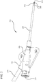
Figure 2 is a detailed perspective view of a catheter with slits of its distal end in accordance with a representative embodiment of the present invention. -
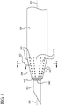
Figure 3 is a perspective view of a catheter tip having slits and an introducer needle extending therethrough in accordance with a representative embodiment of the present invention. -
Figure 4 is a cross section end view of a cannula and catheter prior to fluid infusion in accordance with a representative embodiment of the present invention -
Figure 5 is a perspective side view of a catheter tip following fluid infusion in accordance with a representative embodiment of the present invention. -
Figure 6 is a cross section end view of the catheter tip offigure 5 in accordance with a representative embodiment of the present invention. -
Figure 7 is a perspective side view of a cannula and catheter prior to fluid infusion in accordance with a representative embodiment of the present invention. -
Figure 8 is a cross section view of the catheter tip ofFigure 7 in accordance with a representative embodiment of the present invention. -
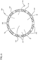
Figure 9 is a cross section end view of the catheter tip ofFigure 8 following removal of the cannula and following fluid infusion in accordance with a representative embodiment of the present invention. - Embodiments of the present invention will be best understood by reference to the drawings, wherein like reference numbers indicate identical or functionally similar elements. It will be readily understood that the components of the present invention, as generally described and illustrated in the figures herein, could be arranged and designed in a wide variety of different configurations. Thus, the following more detailed description, as represented in the figures, is not intended to limit the scope of the invention as claimed, but is merely representative of presently preferred embodiments of the invention.
- It is noted that 1 psi = 6894,76 Pa.
- The systems of the present invention and the methods not forming part of the present invention are generally designed for use in combination with a vascular infusion system capable of rapidly delivering an infusate to the vascular system of a patient. Referring now to
Figure 1 , avascular infusion system 100 is shown, in accordance with a representative embodiment of the present invention. Infusion systems of this type are commonly configured to operate at internal pressures up to 2000 psi. Many systems operate in the range of 75 to 2000 psi, while specific devices of this type operate at 100, 200, and 300 psi. Thevascular infusion system 100 comprises avascular access device 112 coupled to aninjector pump 120 via acoiled extension set 130. In some embodiments, theinfusion system 100 further comprises asafety device 140 positioned between thevascular access device 112 and theinjector pump 120. In some embodiments, asafety device 140 is provided to automatically occlude the fluid path of theinfusion system 100, thereby preventing excessive pressure buildup in downstream infusion components. - An
injector pump 120 generally comprises a fluid pumping apparatus configured to rapidly deliver an infusate, such as blood, medicaments, and CT scan contrast agents to a patient's vascular system. Desirable infusates may also include various fluids often of high viscosity as required for medical and diagnostic procedures. In some embodiments, theinjector pump 120 comprises a power injector capable of delivering an infusate to a patient at flow rates from about 10 mL/hour up to greater than 1500 mL/minute. In some embodiments, a high infusion flow rate is desirable for medical procedures which require enhanced bolus density of an infusate in a patient's vascular system. For example, a trend in diagnostic imaging procedures is to utilize contrast media enhancement, which requires more viscous contrast media to be pushed into a patient at a higher flow rate, thereby resulting in increased image quality. Thus, in some embodiments aninjector pump 120 and avascular access device 112 are selected to compatibly achieve a desired infusion flow rate. - A coiled extension set 130 generally comprises flexible or semi-flexible polymer tubing configured to deliver an infusate from the
injector pump 120 to thevascular access device 112. The extension set 130 includes a first coupler for connecting the extension set 130 to adownstream device second coupler 134 for connecting the extension set 130 to theinjector pump 120. A coiled configuration of the extension set 130 generally prevents undesirable kinking or occlusion of theset 130 during infusion procedures. However, one of skill in the art will appreciate that the extension set 130 may include any configuration capable of efficiently delivering an infusate from aninjector pump 120 to the patient via avascular access device 112. In some embodiments not forming part of the invention , the extension set 130 is coupled between a syringe and a vascular access device whereby an infusate is manually injected into a patient. In other embodiments not forming part of the inventionnot forming part of the invention, the infusion system comprises only a syringe and a vascular access device. - The
vascular access device 112 generally comprises a peripheralintravenous catheter 114. A peripheralintravenous catheter 114 in accordance with the present invention generally comprises a short or truncated catheter (usually 13mm to 52mm) that is inserted into a small peripheral vein. Such catheters generally comprise a diameter of approximately a 14 gauge catheter or smaller. Peripheralintravenous catheters 114 are typically designed for temporary placement. The short length of thecatheter 114 facilitates convenient placement of the catheter but makes them prone to premature dislodging from the vein due to movement of the patient and/or recoil forces experienced during infusion procedures. Furthermore, unlike midline or central peripheral catheters, peripheralintravenous catheters 114 in accordance with the present invention comprise a taperedcatheter tip 146 to accommodate use with an introducer needle (not shown) designed to aid in insertion of thecatheter 114. - The tapered outer surface of the
catheter tip 146 can provide a smooth transition between the narrow diameter of the catheter tip opening and the larger diameter of the catheter tubing. Thus, as thetip 146 of thecatheter 114 is introduced into the vein of a patient, the taperedouter surface 146 facilitates easy insertion of thecatheter 114 through the access hole. The tapered inner surface is generally provided to tightly contact the outer surface of an introducer needle housed within the lumen of the catheter. The introducer needle is provided to create an opening into the vein of patient through which the catheter tip is inserted. The tapered inner surface ensures a tight seal between the inner surface of the catheter and the outer surface of the needle. Following placement of the catheter, the introducer needle is removed. - An introducer needle is typically inserted through the
catheter 114 such that a tip of the needle extends beyond the taperedtip 146. The tapered geometry of the taperedtip 146 conforms tightly to the outer surface of the introducer needle. Both the outer surface and the inner surface of thetip 146 are tapered towards the distal end of thecatheter 114. The outer surface of thetip 146 is tapered to provide a smooth transition from the smaller profile of the introducer needle to the larger profile of the catheter outer diameter. Insertion of the introducer needle into the vein of the patient provides an opening into the vein through which the taperedtip 146 of thecatheter 114 is inserted. The tapered outer surface of thetip 146 enables easy insertion of thecatheter 114 into the opening. Once the peripheralintravenous catheter 114 is inserted into the vein of the patient, the introducer needle (not shown) is removed from the lumen of thecatheter 114 to permit infusion via thecatheter 114. - In some embodiments, an inner surface of the
tip 146 is tapered to provide a secure seal between the inner surface of thecatheter tip 146 and the outer surface of the introducer needle (not shown). Additionally, the tapered inner surface of thetip 146 causes an acceleration of infusate within the lumen of the catheter as the infusate nears and flows through thecatheter tip 146. Following an infusion procedure, the peripheralintravenous catheter 114 is simply removed from vein and discarded. - A desired infusate is typically delivered to the
catheter 114 via a section ofintravenous tubing 116 coupled to thecatheter 114. In some embodiments, a y-adapter 118 is coupled to an end of thetubing 116 opposite thecatheter 114, enabling thevascular access device 112 to be coupled to the remainder of thevascular infusion system 100. One of skill in the art will appreciate the possible variations and specific features of availablevascular access devices 112, as are commonly used in the medical and research professions. For example, in some embodiments acatheter 114 in accordance with the present invention may include additional access sites, clamps, parallel intravenous lines, valves, couplers, introducer needles, coatings, and/or materials as desired to fit a specific application. - Referring now to
Figure 2 , acatheter 214 is shown in accordance with a representative embodiment of the present invention.Catheter 214 generally comprises acatheter adapter 218 configured to house atubular body member 220.Catheter adapter 218 further includes aninlet port 230 that is coupled to a section ofintravenous tubing 216. The section ofintravenous tubing 216 is further coupled to upstream infusion components, as shown and described in connection withFigure 1 , above. - The
catheter adapter 218 facilitates delivery of an infusate within theintravenous tubing 216 to a patient via thetubular body member 220. An inner lumen of thecatheter adapter 218 is in fluid communication with both an inner lumen of theintravenous tubing 216 and an inner lumen of thetubular body member 220. In some embodiments,catheter adapter 218 further comprises anaccess adapter 222. Theaccess adapter 222 is generally provided to permit direct access to the inner lumen of thecatheter adapter 218. In some embodiments, theaccess adapter 222 is accessed via a needle and a syringe to deliver an infusate to a patient via thetubular body member 220. In other embodiments, an introducer needle or guide wire is inserted into theaccess adapter 222 and advanced through the inner lumen of thetubular body member 220. In some embodiments, a tip portion of the introducer needle or guide wire (not shown) extends beyond atip portion 240 of thetubular body member 220. As such, the tip portion of the introducer needle or guide wire may provide an opening into the vascular system of a patient into which thetubular body member 220 is inserted. Following placement of thetubular body member 220 into the vein of the patient, the introducer needle or guide wire is removed from theaccess adapter 222 thereby establishing fluid communication between thetubular body member 220, thecatheter adapter 218 and theintravenous tubing 216. - In some embodiments, the
tubular body member 220 is an intravenous catheter (or catheter body). Theintravenous catheter 214 generally comprises a flexible or semi-flexible biocompatible material, as commonly used in the art. In some embodiments, theintravenous catheter 214 comprises a polymer material, such as polypropylene, polystyrene, polyvinylchloride, polytetrafluoroethylene, and the like. In other embodiments, theintravenous catheter 214 comprises a metallic material, such as surgical steel, titanium, cobalt steel, and the like. - The
tubular body member 220 may comprise any length, where the length is selected based on the intended application of thecatheter 214. For some applications, thetubular body member 220 is inserted into a peripheral vein of the patient. In other applications, thetubular body member 220 is inserted into a central vein of the patient. - For rapid infusion applications, the
tip portion 240 of thetubular body member 220 is modified to include asplittable feature 250. Splittable feature 250 generally allows thecatheter tip 240 to open up or split apart when an infusate is injected throughcatheter 214 at high pressure. As such, the tapered inner and outer surface geometries ofcatheter tip 240 are expanded thereby eliminating any geometric constriction that would otherwise increase the flow velocity exiting thedistal opening 242 of the tubular body member's lumen. Accordingly, for some embodiments the force needed to opensplittable feature 250 is less than the force exerted oncatheter tip 240 by the infusate during high pressure infusion procedures. - In the invention,
splittable feature 250 comprises a closed position prior to being inserted into the vasculature of a patient, as shown inFigure 2 . The closed position ofsplittable feature 250 enables effective insertion ofvenous catheter 214, as discussed above. In particular, the closed position ensures that a close tolerance is maintained betweendistal opening 342 and an outer surface of theintroducer needle 304, as shown inFigure 3 . Thus,catheter tip 340 is able to be easily inserted into the patient's vasculature via an opening provided by the introducer needle. Further, the absence of large diffusion holes provides a continuous outer surface fortubular body 320, thereby preventing any snagging or catching oftubular body 320 on the skin or other tissues of the patient during catheterization. Still further, the absence of large diffusion holes maintains the structural rigidity ofcatheter tip 340, thereby preventing any undesirable crushing or collapsing ofcatheter tip 340 during the catheterization procedure. - With continued reference to
Figures 3 and4 , in the invention splittable feature 350 dividescatheter tip 340 into a plurality of adjacent fingers orsections 343. When in the closed position, as shown, the plurality ofadjacent fingers 343 are connected viasplittable feature 350 thereby forming theclosed catheter tip 340. In some embodiments,splittable feature 350 comprises a line of perforation openings or holes interposed betweenadjacent fingers 343. Aspace 352 between adjacent proximal and distal openings is selected so as to facilitate tearing or separation of the catheter tip material between adjacent proximal and distal openings. Accordingly, when subjected to increased pressures withincatheter body lumen 322, splittable features 350 separate thereby assuming an open position which forms a plurality of separated,adjacent fingers 343, as shown inFigures 5 and6 . - In some embodiments, splittable features 350 are axially oriented, and therefore approximately parallel to a
longitudinal axis 305 ofcatheter 314. In the open position, the plurality of separatedfingers 343 enlarge the effective area ofdistal catheter opening 342 by providing a plurality of extended slits or tapered openings through which aninfusate 324 exitslumen 322. Once the splittable features 350 have been separated, any geometric or structural constriction oftip 340 are eliminated. As such, inner lumen pressures caused byinfusate 324 are reduced and/or eliminated, thereby producing laminar, low pressure flow ofinfusate 324 throughtubular body 320 andcatheter tip 340. - In some embodiments,
splittable feature 450 comprises a plurality of skive lines formed on an inner surface of thetip portion 440 oftubular body 420 ofcatheter 414, as shown inFigures 7-9 . In the invention,splittable feature 450 is provided so as to dividecatheter tip 440 into a plurality of adjacent fingers orsections 443. By locatingsplittable feature 450 on the inner surface ofcatheter tip 440,tip 440 maintains a continuous outer surface thereby preventing any snagging or catching ofcatheter tip 440 on the skin or tissues of the patient during insertion of the catheter into the vasculature of the patient. However, in some embodimentssplittable feature 450 comprises a plurality of skive lines formed on an outer surface oftip portion 440. Further, in some embodimentssplittable feature 450 comprises one or more skive line or lines formed on either the outer surface, the inner surface, or both the outer and inner surfaces oftip portion 440. - When in the closed position, as shown in
Figures 7 and8 , the plurality ofadjacent fingers 443 are connected viasplittable feature 450 thereby forming theclosed catheter tip 440. As such, splittable feature 450 forms a plurality ofgrooves 452 axially oriented, and therefore approximately parallel to alongitudinal axis 405 ofcatheter 414. In some embodiments, the axial orientation ofgrooves 452 provides a plurality of axially oriented ribs or splines 454 which facilitate a more laminar fluid flow of the infusate throughcatheter lumen 422. Further, in someembodiments grooves 452 provide an increased effective inside diameter ofcatheter tip 440. Each of these features, alone or in combination reduces turbulent flow of the infusate, thereby encouraging laminar flow and increasing the effective rate of flow for the infusate. - An apex of each
groove 452 comprises a thin webbing of catheter material having a thickness selected such that the thin webbing is defeated in response to increased pressure withincatheter body lumen 422 during high pressure and/or high velocity infusion procedures. When defeated,splittable feature 450 dividescatheter tip 440 into a plurality of separated,adjacent fingers 443 thereby enlarging the effective surface area of distal catheter opening 442 by providing a plurality of extended slits or taperedopenings 446 through which aninfusate 424 exitslumen 422, as shown inFigure 9 . - Splittable features of the present invention may include any structure, geometry, mechanical function or other mechanism whereby to eliminate a constrictive structure of a catheter tip by expanding the effective area of the distal end opening when exposed to an increased inner lumen pressure. For example, splittable features in accordance with the present invention may include non-linear configurations, as taught in
United States Patent Application Serial No.: 13/053,495 . - Splittable features in accordance with the present invention includes engineered points of weakness within the catheter body and/or catheter tip that are designed to be defeated in response to increased inner lumen pressure during infusion procedures. In some examples not forming part of the invention, a catheter comprises a single splittable feature. In other embodiments, a catheter comprises two or more splittable features. Accordingly, when subjected to increased inner lumen pressure, some catheters of the present invention provide a single finger wherein a single splittable feature is defeated thereby forming a single extended slit or tapered opening through which an infusate exits the lumen of the catheter. In other embodiments, when subjected to increased inner lumen pressure, the catheters of the present invention provide two or more adjacent fingers, wherein two or more splittable features are defeated thereby forming two or more extended slits or tapered openings through which an infusate exits the lumen of the catheter.
- In general, splittable features of the present invention are designed to comprise sufficient structural integrity to maintain the closed position of the catheter tip during insertion of the catheter into the vasculature of the patient. In particular, splittable features of the present invention are provided which are capable of withstanding compressive forces exerted on the catheter tip during insertion into the patient. However, splittable features of the present invention are further designed to be defeated when exposed to increased inner lumen pressures within the tip portion of the catheter under a high pressure application.
- Catheters comprising splittable features in accordance with the present invention may be provided by any known methods in the art. In some embodiments, splittable features of the present invention are provided by molding the splittable feature into the catheter tubing during the tip forming process. For example, splittable features of the present invention may be provided by an injection molding process, use of mechanical processes, and/or via use of a laser. In particular, a desired geometry for making the splittable feature can be included in a tipping mandrel, a tipping die, or both, as well as within the core pin, mold cavity, or both, used to produce and/or manufacture the catheter device.
- The present invention may be embodied in other specific forms without departing from its structures, methods, or other essential characteristics as claimed hereinafter. The described embodiments are to be considered in all respects only as illustrative, and not restrictive. The scope of the invention is, therefore, indicated by the appended claims, rather than by the foregoing description. All changes that come within the meaning and range of equivalency of the claims are to be embraced within their scope.
Claims (5)
- A vascular access device, comprising:a catheter adapter (218) having an inlet port (230) configured to connect the catheter adapter (218) to an injector pump (120); anda catheter body (320, 420) extending from a distal end of the catheter adapter (218), the catheter body (320, 420) having a proximal end, a distal end, a lumen (322, 422) extending between the proximal and distal ends along a longitudinal axis of the catheter body (320, 420), and a distal lumen opening (342, 442), the lumen (322, 422) of the catheter body (320, 420) being in fluid communication with the inlet port (230), wherein the distal end of the catheter body (320, 420) includes a catheter tip (340, 440);characterized in that the catheter tip (340, 440) includes a splittable feature (350, 450) wherein the splittable feature (350, 450) includes a plurality of skive lines formed on an inner surface of the catheter tip (340, 440), wherein the plurality of skive lines divide the catheter tip (340, 440) into a plurality of adjacent fingers (343, 443), wherein the plurality of skive lines are defeated in response to increased pressure in the lumen (322, 422) during infusion, wherein in response to the plurality of skive lines being defeated, the plurality of adjacent fingers (343, 443) separate thereby enlarging an effective surface area of the distal lumen opening (342, 442) by providing a plurality of extended slits or tapered openings.
- The vascular access device of claim 1, further comprising an introducer needle extending through an access adapter (222) of the catheter adapter (218) and through the lumen (322, 422) of the catheter body (320, 420) such that a tip of the introducer needle extends out through the distal lumen opening (320, 442), wherein an inner diameter of the catheter tip (340, 440) conforms tightly to an outer surface of the introducer needle.
- The vascular access device of claim 1, wherein the plurality of skive lines includes three or more skive lines.
- The vascular access device of claim 1, wherein each of the plurality of adjacent fingers (343, 443) is approximately parallel to the longitudinal axis of the catheter body (320, 420).
- The vascular access device of claim 1, wherein the splittable feature (350, 450) is at least partially disposed on a tapered portion of the catheter tip (340, 440).
Applications Claiming Priority (2)
| Application Number | Priority Date | Filing Date | Title |
|---|---|---|---|
| US13/216,029 US9056182B2 (en) | 2011-08-23 | 2011-08-23 | Catheter having a pressure activated splittable feature |
| PCT/US2012/049858 WO2013028348A1 (en) | 2011-08-23 | 2012-08-07 | A catheter having a pressure activated splittable feature |
Publications (2)
| Publication Number | Publication Date |
|---|---|
| EP2747828A1 EP2747828A1 (en) | 2014-07-02 |
| EP2747828B1 true EP2747828B1 (en) | 2021-10-06 |
Family
ID=46650958
Family Applications (1)
| Application Number | Title | Priority Date | Filing Date |
|---|---|---|---|
| EP12746251.3A Active EP2747828B1 (en) | 2011-08-23 | 2012-08-07 | A catheter having a pressure activated splittable feature |
Country Status (10)
| Country | Link |
|---|---|
| US (1) | US9056182B2 (en) |
| EP (1) | EP2747828B1 (en) |
| JP (1) | JP6194311B2 (en) |
| CN (2) | CN103842018B (en) |
| AU (1) | AU2012299355B2 (en) |
| BR (1) | BR112014004322B1 (en) |
| CA (1) | CA2846079C (en) |
| ES (1) | ES2899157T3 (en) |
| MX (1) | MX353425B (en) |
| WO (1) | WO2013028348A1 (en) |
Families Citing this family (25)
| Publication number | Priority date | Publication date | Assignee | Title |
|---|---|---|---|---|
| US8366685B2 (en) | 2011-04-26 | 2013-02-05 | Creative Vascular, Llc | Systems and methods for phlebotomy through a peripheral IV catheter |
| US10076272B2 (en) | 2011-04-26 | 2018-09-18 | Velano Vascular, Inc. | Systems and methods for phlebotomy through a peripheral IV catheter |
| US9056182B2 (en) * | 2011-08-23 | 2015-06-16 | Becton, Dickinson And Company | Catheter having a pressure activated splittable feature |
| ITCT20130016A1 (en) * | 2013-07-04 | 2015-01-05 | Stefano Riccardo De | CANNULA FOR ENDOVENOUS CATHETER AND METHOD FOR ITS REALIZATION |
| US9629981B2 (en) * | 2013-12-13 | 2017-04-25 | Dolcera Information Technology Services Private Limited | Drainage catheter |
| JP2018515196A (en) * | 2015-05-06 | 2018-06-14 | ローテーション メディカル インコーポレイテッドRotation Medical,Inc. | Medical implant delivery system and related methods |
| US9814824B2 (en) | 2015-06-01 | 2017-11-14 | Asia Pacific Medical Technology Development Company, Ltd | Systems and methods for extracorporeal support |
| US10532185B2 (en) | 2015-09-08 | 2020-01-14 | Covidien Lp | Navigable catheter distal tip configuration |
| CN105126231A (en) * | 2015-09-15 | 2015-12-09 | 仇汉诚 | Balloon catheter |
| CN105107077A (en) * | 2015-09-15 | 2015-12-02 | 仇汉诚 | Micro catheter |
| EP3370798B1 (en) * | 2015-11-04 | 2020-09-23 | Asia Pacific Medical Technology Development Company, Ltd | Systems and methods for flow stagnation control |
| US10213542B2 (en) | 2015-11-04 | 2019-02-26 | Asia Pacific Medical Technology Development Company, Ltd | Systems and methods for flow stagnation control |
| US10265460B2 (en) | 2015-11-04 | 2019-04-23 | Asia Pacific Medical Technology Development Company, Ltd. | Systems and methods for providing zones of selective thermal therapy |
| EP4385409A3 (en) | 2017-03-21 | 2024-09-25 | Velano Vascular, Inc. | Devices for fluid transfer through a placed peripheral intravenous catheter |
| EP4059556A1 (en) | 2017-03-21 | 2022-09-21 | Velano Vascular, Inc. | Methods for controlling catheter device size |
| US10967159B2 (en) * | 2017-08-31 | 2021-04-06 | Acclarent, Inc. | Sinuplasty guide with plurality of configurations |
| WO2019094643A1 (en) * | 2017-11-09 | 2019-05-16 | Corinth MedTech, Inc. | Surgical devices and methods |
| WO2019152377A1 (en) | 2018-01-30 | 2019-08-08 | Hsu George Chao Chih | Surgical device and methods |
| CN109045400B (en) * | 2018-10-10 | 2024-06-25 | 常州市第二人民医院 | Reinforced CT anti-extravasation indwelling needle |
| BR112022003098A2 (en) | 2019-08-20 | 2022-05-17 | Velano Vascular Inc | Fluid transfer devices with extended-length catheters and methods of using the same |
| US12336751B2 (en) | 2019-08-26 | 2025-06-24 | Aulea Medical, Inc. | Surgical device and methods |
| CN113893074B (en) * | 2020-07-06 | 2025-10-17 | 杭州启明医疗器械股份有限公司 | Sheath distal structure and sheath for delivering interventional instruments |
| US20220161003A1 (en) | 2020-11-26 | 2022-05-26 | Avia Vascular, Llc | Blood collection devices, systems, and methods |
| US12575875B2 (en) | 2021-12-17 | 2026-03-17 | Aulea Medical, Inc. | Surgical device and methods |
| CN119236269B (en) * | 2024-10-18 | 2025-12-26 | 杭州心畅医疗器械有限公司 | Can dilate vascular sheath |
Citations (2)
| Publication number | Priority date | Publication date | Assignee | Title |
|---|---|---|---|---|
| US6080141A (en) * | 1997-12-22 | 2000-06-27 | Becton, Dickinson And Company | Splittable tubular medical device and method for manufacture |
| US20070225659A1 (en) * | 2006-03-21 | 2007-09-27 | Cook Incorporated | Introducer sheath having frangible tip |
Family Cites Families (55)
| Publication number | Priority date | Publication date | Assignee | Title |
|---|---|---|---|---|
| US3713442A (en) | 1970-09-08 | 1973-01-30 | H Walter | Split needle assembly for catheter tube |
| US4563180A (en) | 1984-06-29 | 1986-01-07 | Raychem Corporation | High flow catheter for injecting fluids |
| US4661094A (en) | 1985-05-03 | 1987-04-28 | Advanced Cardiovascular Systems | Perfusion catheter and method |
| GR851148B (en) | 1985-05-13 | 1985-05-22 | Papantonakos Apostolos | |
| US4738666A (en) * | 1985-06-11 | 1988-04-19 | Genus Catheter Technologies, Inc. | Variable diameter catheter |
| US4952359A (en) * | 1987-02-06 | 1990-08-28 | Becton, Dickinson And Company | Method for making splittable catheter |
| US4863441A (en) | 1987-07-17 | 1989-09-05 | Minnesota Mining And Manufacturing Company | Venous return catheter |
| US4784638A (en) | 1987-09-17 | 1988-11-15 | Neurodynamics, Inc. | Angled hole ventricular catheter and method of making same |
| CA1320088C (en) * | 1988-05-09 | 1993-07-13 | Becton, Dickinson And Company | Splittable introducer catheter with modified tip |
| US4961731A (en) | 1988-06-09 | 1990-10-09 | Sherwood Medical Company | Angiographic catheter with balanced dye injection openings |
| US5088991A (en) | 1988-07-14 | 1992-02-18 | Novoste Corporation | Fuseless soft tip angiographic catheter |
| US4968307A (en) | 1989-01-09 | 1990-11-06 | Advanced Cardiovascular Systems, Inc. | Catheter for uniform distribution of therapeutic fluids |
| US5037403A (en) | 1989-11-08 | 1991-08-06 | Cordis Corporation | Pigtail catheter with angled apertures |
| US5085635A (en) | 1990-05-18 | 1992-02-04 | Cragg Andrew H | Valved-tip angiographic catheter |
| US5843017A (en) | 1990-07-24 | 1998-12-01 | Yoon; Inbae | Multifunctional tissue dissecting instrument |
| US5250034A (en) | 1990-09-17 | 1993-10-05 | E-Z-Em, Inc. | Pressure responsive valve catheter |
| US5267979A (en) | 1990-09-17 | 1993-12-07 | E-Z-Em, Inc. | Pressure responsive valve catheter |
| US5201723A (en) | 1991-08-27 | 1993-04-13 | Cordis Corporation | Inclined side holes in the distal end of a catheter |
| DE4208912C1 (en) | 1992-03-20 | 1993-05-19 | Rudolf 5300 Bonn De Schoen | |
| US5234406A (en) | 1992-04-06 | 1993-08-10 | The Regents Of The University Of California | Method and system for continuous spinal delivery of anesthetics |
| US5334154A (en) | 1992-08-04 | 1994-08-02 | Advanced Cardiovascular Systems, Inc. | Perfusion type dilatation catheter having perfusion ports with depressed proximal edges |
| US5380307A (en) | 1992-09-30 | 1995-01-10 | Target Therapeutics, Inc. | Catheter with atraumatic drug delivery tip |
| US5542925A (en) | 1993-11-05 | 1996-08-06 | Advanced Cardiovascular Systems, Inc. | Dilatation catheter with oblong perfusion ports |
| US5536261A (en) | 1994-09-01 | 1996-07-16 | Stevens; Robert C. | Method and closed tip effect catheter apparatus for use in angiography |
| US5616137A (en) | 1995-02-22 | 1997-04-01 | Minnesota Mining And Manufacturing Company | Low velocity aortic cannula |
| US5647846A (en) | 1995-05-17 | 1997-07-15 | Scimed Life Systems, Inc. | Catheter having geometrically shaped surface and method of manufacture |
| US6052612A (en) | 1995-06-07 | 2000-04-18 | Desai; Jawahar M. | Catheter for media injection |
| US5857464A (en) | 1995-06-07 | 1999-01-12 | Desai; Jawahar M. | Catheter for media injection |
| SE505125C2 (en) | 1995-10-10 | 1997-06-30 | Gambro Ab | Catheter, especially for peritoneal dialysis |
| US5830181A (en) | 1997-02-07 | 1998-11-03 | Advanced Cardiovascular Systems, Inc. | Perfusion catheter with high flow distal tip |
| JP3685617B2 (en) | 1998-03-31 | 2005-08-24 | テルモ株式会社 | catheter |
| US6293958B1 (en) | 1998-07-27 | 2001-09-25 | Acist Medical Systems, Inc. | Catheter having flow diffusing tip |
| US6129700A (en) | 1998-12-04 | 2000-10-10 | Advanced Cardiovascular Systems, Inc. | Contrast medium injection device and method of use |
| US6743196B2 (en) | 1999-03-01 | 2004-06-01 | Coaxia, Inc. | Partial aortic occlusion devices and methods for cerebral perfusion augmentation |
| US6514236B1 (en) | 1999-04-23 | 2003-02-04 | Alexander A. Stratienko | Method for treating a cardiovascular condition |
| US6241710B1 (en) | 1999-12-20 | 2001-06-05 | Tricardia Llc | Hypodermic needle with weeping tip and method of use |
| US6669679B1 (en) | 2000-01-07 | 2003-12-30 | Acist Medical Systems, Inc. | Anti-recoil catheter |
| WO2001091830A1 (en) | 2000-05-25 | 2001-12-06 | Loma Linda University Medical Center | Implantable fluid delivery system |
| US7108674B2 (en) | 2000-08-30 | 2006-09-19 | Radius International Limited Partnership | Catheter |
| US20020072712A1 (en) | 2000-10-12 | 2002-06-13 | Nool Jeffrey A. | Medical wire introducer and protective sheath |
| US6641564B1 (en) | 2000-11-06 | 2003-11-04 | Medamicus, Inc. | Safety introducer apparatus and method therefor |
| US6969373B2 (en) | 2001-04-13 | 2005-11-29 | Tricardia, Llc | Syringe system |
| AU2002320187A1 (en) * | 2001-06-29 | 2003-03-03 | A.B. Korkor Medical, Inc. | Catheter introducer having an expandable tip |
| US6866655B2 (en) | 2002-04-23 | 2005-03-15 | Scimed Life Systems, Inc. | Medical device with atraumatic tip |
| US7300429B2 (en) | 2003-03-18 | 2007-11-27 | Catharos Medical Systems, Inc. | Methods and devices for retrieval of a medical agent from a physiological efferent fluid collection site |
| EP1682199A4 (en) | 2003-11-15 | 2008-03-12 | Medrad Inc | Catheter for diagnostic imaging and therapeutic procedures |
| US7860555B2 (en) | 2005-02-02 | 2010-12-28 | Voyage Medical, Inc. | Tissue visualization and manipulation system |
| JP4754626B2 (en) * | 2005-04-28 | 2011-08-24 | セント・ジュード・メディカル・エイトリアル・フィブリレーション・ディヴィジョン・インコーポレーテッド | Tearable atraumatic tip and body for a catheter or sheath |
| JP2007175297A (en) * | 2005-12-28 | 2007-07-12 | Toray Ind Inc | catheter |
| US7909798B2 (en) * | 2007-07-25 | 2011-03-22 | Oscor Inc. | Peel-away introducer sheath having pitched peel lines and method of making same |
| US8066660B2 (en) * | 2007-10-26 | 2011-11-29 | C. R. Bard, Inc. | Split-tip catheter including lateral distal openings |
| US9364634B2 (en) | 2008-04-22 | 2016-06-14 | Becton, Dickinson And Company | Systems and methods for improving catheter hole array efficiency |
| US9393382B2 (en) | 2009-05-05 | 2016-07-19 | Robert W. Heck | High-flow tapered peripheral IV catheter with side outlets |
| US8262619B2 (en) * | 2010-09-30 | 2012-09-11 | Tyco Healthcare Group Lp | Introducer sheath for catheters |
| US9056182B2 (en) * | 2011-08-23 | 2015-06-16 | Becton, Dickinson And Company | Catheter having a pressure activated splittable feature |
-
2011
- 2011-08-23 US US13/216,029 patent/US9056182B2/en active Active
-
2012
- 2012-08-07 ES ES12746251T patent/ES2899157T3/en active Active
- 2012-08-07 AU AU2012299355A patent/AU2012299355B2/en active Active
- 2012-08-07 BR BR112014004322-1A patent/BR112014004322B1/en active IP Right Grant
- 2012-08-07 CN CN201280048702.6A patent/CN103842018B/en active Active
- 2012-08-07 MX MX2014002139A patent/MX353425B/en active IP Right Grant
- 2012-08-07 JP JP2014527163A patent/JP6194311B2/en active Active
- 2012-08-07 EP EP12746251.3A patent/EP2747828B1/en active Active
- 2012-08-07 CA CA2846079A patent/CA2846079C/en active Active
- 2012-08-07 WO PCT/US2012/049858 patent/WO2013028348A1/en not_active Ceased
- 2012-08-21 CN CN2012204165993U patent/CN202844307U/en not_active Expired - Lifetime
Patent Citations (2)
| Publication number | Priority date | Publication date | Assignee | Title |
|---|---|---|---|---|
| US6080141A (en) * | 1997-12-22 | 2000-06-27 | Becton, Dickinson And Company | Splittable tubular medical device and method for manufacture |
| US20070225659A1 (en) * | 2006-03-21 | 2007-09-27 | Cook Incorporated | Introducer sheath having frangible tip |
Also Published As
| Publication number | Publication date |
|---|---|
| US9056182B2 (en) | 2015-06-16 |
| CA2846079C (en) | 2019-04-02 |
| EP2747828A1 (en) | 2014-07-02 |
| CA2846079A1 (en) | 2013-02-28 |
| JP2014524333A (en) | 2014-09-22 |
| CN202844307U (en) | 2013-04-03 |
| US20130053825A1 (en) | 2013-02-28 |
| ES2899157T3 (en) | 2022-03-10 |
| NZ621749A (en) | 2015-09-25 |
| MX2014002139A (en) | 2014-03-27 |
| JP6194311B2 (en) | 2017-09-06 |
| BR112014004322B1 (en) | 2021-02-23 |
| CN103842018A (en) | 2014-06-04 |
| BR112014004322A2 (en) | 2017-03-28 |
| AU2012299355B2 (en) | 2016-09-22 |
| AU2012299355A1 (en) | 2014-03-13 |
| MX353425B (en) | 2018-01-12 |
| WO2013028348A1 (en) | 2013-02-28 |
| CN103842018B (en) | 2016-09-14 |
Similar Documents
| Publication | Publication Date | Title |
|---|---|---|
| US9056182B2 (en) | Catheter having a pressure activated splittable feature | |
| US10478592B2 (en) | Systems and methods to increase rigidity and snag-resistance of catheter tip | |
| EP2621577B1 (en) | Methods for improving catheter hole array efficiency | |
| US8936581B2 (en) | Catheter having a spiral slit | |
| JP2011518024A (en) | Systems and methods for improving the efficiency of catheter hole arrays | |
| NZ621749B2 (en) | A catheter having a pressure activated splittable feature | |
| NZ621752B2 (en) | Systems and methods to increase rigidity and snag-resistance of catheter tip |
Legal Events
| Date | Code | Title | Description |
|---|---|---|---|
| PUAI | Public reference made under article 153(3) epc to a published international application that has entered the european phase |
Free format text: ORIGINAL CODE: 0009012 |
|
| 17P | Request for examination filed |
Effective date: 20140317 |
|
| AK | Designated contracting states |
Kind code of ref document: A1 Designated state(s): AL AT BE BG CH CY CZ DE DK EE ES FI FR GB GR HR HU IE IS IT LI LT LU LV MC MK MT NL NO PL PT RO RS SE SI SK SM TR |
|
| DAX | Request for extension of the european patent (deleted) | ||
| RAP1 | Party data changed (applicant data changed or rights of an application transferred) |
Owner name: BECTON, DICKINSON AND COMPANY |
|
| STAA | Information on the status of an ep patent application or granted ep patent |
Free format text: STATUS: EXAMINATION IS IN PROGRESS |
|
| 17Q | First examination report despatched |
Effective date: 20170620 |
|
| GRAP | Despatch of communication of intention to grant a patent |
Free format text: ORIGINAL CODE: EPIDOSNIGR1 |
|
| STAA | Information on the status of an ep patent application or granted ep patent |
Free format text: STATUS: GRANT OF PATENT IS INTENDED |
|
| RIC1 | Information provided on ipc code assigned before grant |
Ipc: A61M 25/00 20060101AFI20210421BHEP Ipc: A61M 25/01 20060101ALI20210421BHEP Ipc: A61M 25/06 20060101ALI20210421BHEP |
|
| INTG | Intention to grant announced |
Effective date: 20210514 |
|
| GRAS | Grant fee paid |
Free format text: ORIGINAL CODE: EPIDOSNIGR3 |
|
| GRAA | (expected) grant |
Free format text: ORIGINAL CODE: 0009210 |
|
| STAA | Information on the status of an ep patent application or granted ep patent |
Free format text: STATUS: THE PATENT HAS BEEN GRANTED |
|
| AK | Designated contracting states |
Kind code of ref document: B1 Designated state(s): AL AT BE BG CH CY CZ DE DK EE ES FI FR GB GR HR HU IE IS IT LI LT LU LV MC MK MT NL NO PL PT RO RS SE SI SK SM TR |
|
| REG | Reference to a national code |
Ref country code: GB Ref legal event code: FG4D |
|
| REG | Reference to a national code |
Ref country code: CH Ref legal event code: EP Ref country code: AT Ref legal event code: REF Ref document number: 1435701 Country of ref document: AT Kind code of ref document: T Effective date: 20211015 |
|
| REG | Reference to a national code |
Ref country code: DE Ref legal event code: R096 Ref document number: 602012076856 Country of ref document: DE |
|
| REG | Reference to a national code |
Ref country code: IE Ref legal event code: FG4D |
|
| REG | Reference to a national code |
Ref country code: LT Ref legal event code: MG9D |
|
| REG | Reference to a national code |
Ref country code: NL Ref legal event code: MP Effective date: 20211006 |
|
| REG | Reference to a national code |
Ref country code: ES Ref legal event code: FG2A Ref document number: 2899157 Country of ref document: ES Kind code of ref document: T3 Effective date: 20220310 |
|
| REG | Reference to a national code |
Ref country code: AT Ref legal event code: MK05 Ref document number: 1435701 Country of ref document: AT Kind code of ref document: T Effective date: 20211006 |
|
| PG25 | Lapsed in a contracting state [announced via postgrant information from national office to epo] |
Ref country code: RS Free format text: LAPSE BECAUSE OF FAILURE TO SUBMIT A TRANSLATION OF THE DESCRIPTION OR TO PAY THE FEE WITHIN THE PRESCRIBED TIME-LIMIT Effective date: 20211006 Ref country code: LT Free format text: LAPSE BECAUSE OF FAILURE TO SUBMIT A TRANSLATION OF THE DESCRIPTION OR TO PAY THE FEE WITHIN THE PRESCRIBED TIME-LIMIT Effective date: 20211006 Ref country code: FI Free format text: LAPSE BECAUSE OF FAILURE TO SUBMIT A TRANSLATION OF THE DESCRIPTION OR TO PAY THE FEE WITHIN THE PRESCRIBED TIME-LIMIT Effective date: 20211006 Ref country code: BG Free format text: LAPSE BECAUSE OF FAILURE TO SUBMIT A TRANSLATION OF THE DESCRIPTION OR TO PAY THE FEE WITHIN THE PRESCRIBED TIME-LIMIT Effective date: 20220106 Ref country code: AT Free format text: LAPSE BECAUSE OF FAILURE TO SUBMIT A TRANSLATION OF THE DESCRIPTION OR TO PAY THE FEE WITHIN THE PRESCRIBED TIME-LIMIT Effective date: 20211006 |
|
| PG25 | Lapsed in a contracting state [announced via postgrant information from national office to epo] |
Ref country code: IS Free format text: LAPSE BECAUSE OF FAILURE TO SUBMIT A TRANSLATION OF THE DESCRIPTION OR TO PAY THE FEE WITHIN THE PRESCRIBED TIME-LIMIT Effective date: 20220206 Ref country code: SE Free format text: LAPSE BECAUSE OF FAILURE TO SUBMIT A TRANSLATION OF THE DESCRIPTION OR TO PAY THE FEE WITHIN THE PRESCRIBED TIME-LIMIT Effective date: 20211006 Ref country code: PT Free format text: LAPSE BECAUSE OF FAILURE TO SUBMIT A TRANSLATION OF THE DESCRIPTION OR TO PAY THE FEE WITHIN THE PRESCRIBED TIME-LIMIT Effective date: 20220207 Ref country code: PL Free format text: LAPSE BECAUSE OF FAILURE TO SUBMIT A TRANSLATION OF THE DESCRIPTION OR TO PAY THE FEE WITHIN THE PRESCRIBED TIME-LIMIT Effective date: 20211006 Ref country code: NO Free format text: LAPSE BECAUSE OF FAILURE TO SUBMIT A TRANSLATION OF THE DESCRIPTION OR TO PAY THE FEE WITHIN THE PRESCRIBED TIME-LIMIT Effective date: 20220106 Ref country code: NL Free format text: LAPSE BECAUSE OF FAILURE TO SUBMIT A TRANSLATION OF THE DESCRIPTION OR TO PAY THE FEE WITHIN THE PRESCRIBED TIME-LIMIT Effective date: 20211006 Ref country code: LV Free format text: LAPSE BECAUSE OF FAILURE TO SUBMIT A TRANSLATION OF THE DESCRIPTION OR TO PAY THE FEE WITHIN THE PRESCRIBED TIME-LIMIT Effective date: 20211006 Ref country code: HR Free format text: LAPSE BECAUSE OF FAILURE TO SUBMIT A TRANSLATION OF THE DESCRIPTION OR TO PAY THE FEE WITHIN THE PRESCRIBED TIME-LIMIT Effective date: 20211006 Ref country code: GR Free format text: LAPSE BECAUSE OF FAILURE TO SUBMIT A TRANSLATION OF THE DESCRIPTION OR TO PAY THE FEE WITHIN THE PRESCRIBED TIME-LIMIT Effective date: 20220107 |
|
| REG | Reference to a national code |
Ref country code: DE Ref legal event code: R097 Ref document number: 602012076856 Country of ref document: DE |
|
| PG25 | Lapsed in a contracting state [announced via postgrant information from national office to epo] |
Ref country code: SM Free format text: LAPSE BECAUSE OF FAILURE TO SUBMIT A TRANSLATION OF THE DESCRIPTION OR TO PAY THE FEE WITHIN THE PRESCRIBED TIME-LIMIT Effective date: 20211006 Ref country code: SK Free format text: LAPSE BECAUSE OF FAILURE TO SUBMIT A TRANSLATION OF THE DESCRIPTION OR TO PAY THE FEE WITHIN THE PRESCRIBED TIME-LIMIT Effective date: 20211006 Ref country code: RO Free format text: LAPSE BECAUSE OF FAILURE TO SUBMIT A TRANSLATION OF THE DESCRIPTION OR TO PAY THE FEE WITHIN THE PRESCRIBED TIME-LIMIT Effective date: 20211006 Ref country code: EE Free format text: LAPSE BECAUSE OF FAILURE TO SUBMIT A TRANSLATION OF THE DESCRIPTION OR TO PAY THE FEE WITHIN THE PRESCRIBED TIME-LIMIT Effective date: 20211006 Ref country code: DK Free format text: LAPSE BECAUSE OF FAILURE TO SUBMIT A TRANSLATION OF THE DESCRIPTION OR TO PAY THE FEE WITHIN THE PRESCRIBED TIME-LIMIT Effective date: 20211006 Ref country code: CZ Free format text: LAPSE BECAUSE OF FAILURE TO SUBMIT A TRANSLATION OF THE DESCRIPTION OR TO PAY THE FEE WITHIN THE PRESCRIBED TIME-LIMIT Effective date: 20211006 |
|
| PLBE | No opposition filed within time limit |
Free format text: ORIGINAL CODE: 0009261 |
|
| STAA | Information on the status of an ep patent application or granted ep patent |
Free format text: STATUS: NO OPPOSITION FILED WITHIN TIME LIMIT |
|
| 26N | No opposition filed |
Effective date: 20220707 |
|
| PG25 | Lapsed in a contracting state [announced via postgrant information from national office to epo] |
Ref country code: AL Free format text: LAPSE BECAUSE OF FAILURE TO SUBMIT A TRANSLATION OF THE DESCRIPTION OR TO PAY THE FEE WITHIN THE PRESCRIBED TIME-LIMIT Effective date: 20211006 |
|
| PG25 | Lapsed in a contracting state [announced via postgrant information from national office to epo] |
Ref country code: SI Free format text: LAPSE BECAUSE OF FAILURE TO SUBMIT A TRANSLATION OF THE DESCRIPTION OR TO PAY THE FEE WITHIN THE PRESCRIBED TIME-LIMIT Effective date: 20211006 |
|
| PG25 | Lapsed in a contracting state [announced via postgrant information from national office to epo] |
Ref country code: MC Free format text: LAPSE BECAUSE OF FAILURE TO SUBMIT A TRANSLATION OF THE DESCRIPTION OR TO PAY THE FEE WITHIN THE PRESCRIBED TIME-LIMIT Effective date: 20211006 |
|
| REG | Reference to a national code |
Ref country code: CH Ref legal event code: PL |
|
| PG25 | Lapsed in a contracting state [announced via postgrant information from national office to epo] |
Ref country code: LU Free format text: LAPSE BECAUSE OF NON-PAYMENT OF DUE FEES Effective date: 20220807 Ref country code: LI Free format text: LAPSE BECAUSE OF NON-PAYMENT OF DUE FEES Effective date: 20220831 Ref country code: CH Free format text: LAPSE BECAUSE OF NON-PAYMENT OF DUE FEES Effective date: 20220831 |
|
| PG25 | Lapsed in a contracting state [announced via postgrant information from national office to epo] |
Ref country code: IE Free format text: LAPSE BECAUSE OF NON-PAYMENT OF DUE FEES Effective date: 20220807 |
|
| PG25 | Lapsed in a contracting state [announced via postgrant information from national office to epo] |
Ref country code: HU Free format text: LAPSE BECAUSE OF FAILURE TO SUBMIT A TRANSLATION OF THE DESCRIPTION OR TO PAY THE FEE WITHIN THE PRESCRIBED TIME-LIMIT; INVALID AB INITIO Effective date: 20120807 |
|
| PG25 | Lapsed in a contracting state [announced via postgrant information from national office to epo] |
Ref country code: CY Free format text: LAPSE BECAUSE OF FAILURE TO SUBMIT A TRANSLATION OF THE DESCRIPTION OR TO PAY THE FEE WITHIN THE PRESCRIBED TIME-LIMIT Effective date: 20211006 |
|
| PG25 | Lapsed in a contracting state [announced via postgrant information from national office to epo] |
Ref country code: MK Free format text: LAPSE BECAUSE OF FAILURE TO SUBMIT A TRANSLATION OF THE DESCRIPTION OR TO PAY THE FEE WITHIN THE PRESCRIBED TIME-LIMIT Effective date: 20211006 |
|
| PG25 | Lapsed in a contracting state [announced via postgrant information from national office to epo] |
Ref country code: TR Free format text: LAPSE BECAUSE OF FAILURE TO SUBMIT A TRANSLATION OF THE DESCRIPTION OR TO PAY THE FEE WITHIN THE PRESCRIBED TIME-LIMIT Effective date: 20211006 |
|
| PG25 | Lapsed in a contracting state [announced via postgrant information from national office to epo] |
Ref country code: MT Free format text: LAPSE BECAUSE OF FAILURE TO SUBMIT A TRANSLATION OF THE DESCRIPTION OR TO PAY THE FEE WITHIN THE PRESCRIBED TIME-LIMIT Effective date: 20211006 |
|
| PGFP | Annual fee paid to national office [announced via postgrant information from national office to epo] |
Ref country code: ES Payment date: 20250901 Year of fee payment: 14 |
|
| PGFP | Annual fee paid to national office [announced via postgrant information from national office to epo] |
Ref country code: DE Payment date: 20250724 Year of fee payment: 14 |
|
| PGFP | Annual fee paid to national office [announced via postgrant information from national office to epo] |
Ref country code: IT Payment date: 20250723 Year of fee payment: 14 |
|
| PGFP | Annual fee paid to national office [announced via postgrant information from national office to epo] |
Ref country code: BE Payment date: 20250723 Year of fee payment: 14 Ref country code: GB Payment date: 20250725 Year of fee payment: 14 |
|
| PGFP | Annual fee paid to national office [announced via postgrant information from national office to epo] |
Ref country code: FR Payment date: 20250723 Year of fee payment: 14 |