EP2747450A1 - Electronic device - Google Patents
Electronic device Download PDFInfo
- Publication number
- EP2747450A1 EP2747450A1 EP12824339.1A EP12824339A EP2747450A1 EP 2747450 A1 EP2747450 A1 EP 2747450A1 EP 12824339 A EP12824339 A EP 12824339A EP 2747450 A1 EP2747450 A1 EP 2747450A1
- Authority
- EP
- European Patent Office
- Prior art keywords
- wave
- electronic device
- oscillator
- modulation
- sound
- Prior art date
- Legal status (The legal status is an assumption and is not a legal conclusion. Google has not performed a legal analysis and makes no representation as to the accuracy of the status listed.)
- Withdrawn
Links
Images



Classifications
-
- G—PHYSICS
- G01—MEASURING; TESTING
- G01S—RADIO DIRECTION-FINDING; RADIO NAVIGATION; DETERMINING DISTANCE OR VELOCITY BY USE OF RADIO WAVES; LOCATING OR PRESENCE-DETECTING BY USE OF THE REFLECTION OR RERADIATION OF RADIO WAVES; ANALOGOUS ARRANGEMENTS USING OTHER WAVES
- G01S7/00—Details of systems according to groups G01S13/00, G01S15/00, G01S17/00
- G01S7/52—Details of systems according to groups G01S13/00, G01S15/00, G01S17/00 of systems according to group G01S15/00
-
- G—PHYSICS
- G01—MEASURING; TESTING
- G01S—RADIO DIRECTION-FINDING; RADIO NAVIGATION; DETERMINING DISTANCE OR VELOCITY BY USE OF RADIO WAVES; LOCATING OR PRESENCE-DETECTING BY USE OF THE REFLECTION OR RERADIATION OF RADIO WAVES; ANALOGOUS ARRANGEMENTS USING OTHER WAVES
- G01S11/00—Systems for determining distance or velocity not using reflection or reradiation
- G01S11/14—Systems for determining distance or velocity not using reflection or reradiation using ultrasonic, sonic or infrasonic waves
-
- G—PHYSICS
- G01—MEASURING; TESTING
- G01S—RADIO DIRECTION-FINDING; RADIO NAVIGATION; DETERMINING DISTANCE OR VELOCITY BY USE OF RADIO WAVES; LOCATING OR PRESENCE-DETECTING BY USE OF THE REFLECTION OR RERADIATION OF RADIO WAVES; ANALOGOUS ARRANGEMENTS USING OTHER WAVES
- G01S15/00—Systems using the reflection or reradiation of acoustic waves, e.g. sonar systems
- G01S15/02—Systems using the reflection or reradiation of acoustic waves, e.g. sonar systems using reflection of acoustic waves
-
- G—PHYSICS
- G10—MUSICAL INSTRUMENTS; ACOUSTICS
- G10K—SOUND-PRODUCING DEVICES; METHODS OR DEVICES FOR PROTECTING AGAINST, OR FOR DAMPING, NOISE OR OTHER ACOUSTIC WAVES IN GENERAL; ACOUSTICS NOT OTHERWISE PROVIDED FOR
- G10K11/00—Methods or devices for transmitting, conducting or directing sound in general; Methods or devices for protecting against, or for damping, noise or other acoustic waves in general
- G10K11/18—Methods or devices for transmitting, conducting or directing sound
-
- G—PHYSICS
- G10—MUSICAL INSTRUMENTS; ACOUSTICS
- G10K—SOUND-PRODUCING DEVICES; METHODS OR DEVICES FOR PROTECTING AGAINST, OR FOR DAMPING, NOISE OR OTHER ACOUSTIC WAVES IN GENERAL; ACOUSTICS NOT OTHERWISE PROVIDED FOR
- G10K15/00—Acoustics not otherwise provided for
- G10K15/02—Synthesis of acoustic waves
-
- H—ELECTRICITY
- H04—ELECTRIC COMMUNICATION TECHNIQUE
- H04R—LOUDSPEAKERS, MICROPHONES, GRAMOPHONE PICK-UPS OR LIKE ACOUSTIC ELECTROMECHANICAL TRANSDUCERS; ELECTRIC HEARING AIDS; PUBLIC ADDRESS SYSTEMS
- H04R2217/00—Details of magnetostrictive, piezoelectric, or electrostrictive transducers covered by H04R15/00 or H04R17/00 but not provided for in any of their subgroups
- H04R2217/03—Parametric transducers where sound is generated or captured by the acoustic demodulation of amplitude modulated ultrasonic waves
Definitions
- the present invention relates to an electronic device including an oscillator.
- Techniques regarding a speaker have been examined variously, and include a technique using, for example, an oscillator that outputs ultrasound waves. It is possible to form a sound field having a high directivity by using an oscillator that oscillates ultrasound waves for sound reproduction using a speaker. Examples of a technique regarding a speaker using ultrasound waves include techniques disclosed in Patent Document 1 to Patent Document 3. All of Patent Document 1 to Patent Document 3 include techniques regarding a parametric speaker using a nonlinear phenomenon of ultrasound waves.
- Patent Document 1 phase adjustment of high-frequency carrier waves is controlled to change a direction of a sound which is emitted from a vibrator group.
- Patent Document 2 discloses that the frequency of carrier waves is changed and output in accordance with a distance to a target person.
- Patent Document 3 a plurality of piezoelectric elements having different resonance frequencies are provided so as to allow a carrier wave to be selected.
- a carrier frequency of a modulation wave is selected, and thus it is possible to adjust the directivity of ultrasound waves that are output from an oscillator.
- a frequency characteristic of a sound wave that is demodulated is different for each carrier frequency that is selected.
- An object of the invention is to provide an electronic device capable of correcting a frequency characteristic of a sound wave that is demodulated, for each carrier frequency of a modulation wave.
- an electronic device including a modulation unit that modulates a sound signal to a modulation wave for a parametric speaker; an oscillator to which the modulation wave is input; an equalizer that corrects a frequency characteristic of a sound wave that is demodulated by the modulation wave; and a control unit that selects a carrier frequency of the modulation wave and changes setting of the equalizer on the basis of the selected carrier frequency.
- an electronic device capable of correcting a frequency characteristic of a sound wave that is demodulated, for each carrier frequency of a modulation wave.
- FIG. 1 is a block diagram illustrating an electronic device 100 according to a first embodiment.
- the electronic device 100 includes a modulation unit 22, an oscillator 12, an equalizer 26, and a control unit 20.
- the electronic device 100 is a portable terminal device such as a cellular phone.
- the modulation unit 22 modulates a sound signal to a modulation wave for a parametric speaker.
- the modulation wave is input to the oscillator 12.
- the equalizer 26 corrects a frequency characteristic of a sound wave which is demodulated by the modulation wave.
- the control unit 20 selects a carrier frequency of the modulation wave. In addition, the control unit 20 changes the setting of the equalizer 26 on the basis of the selected carrier frequency.
- the electronic device 100 performs sound reproduction using an operation principle of a parametric speaker.
- the operation principle of the parametric speaker is as follows.
- the parametric speaker performs sound reproduction based on a principle in which ultrasound waves on which an AM modulation, a DSB modulation, an SSB modulation, or an FM modulation is performed are emitted into the air and in which an audible sound is issued by a non-linear characteristic when ultrasound waves are propagated into the air.
- non-linear herein indicates a transition from a laminar flow to a turbulent flow when the Reynolds number expressed by the ratio of the inertial action and the viscous action of a flow increases.
- the sound wave is very slightly disturbed within a fluid, the sound wave is propagated non-linearly.
- the ultrasound waves are emitted into the air, high harmonic waves associated with the non-linearity are conspicuously generated.
- the sound wave is in a sparse and dense state in which light and shade occur in the molecular density in the air.
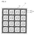
- FIG. 2 is a plan view illustrating the array speaker 10 shown in FIG. 1 .
- the electronic device 100 includes the plurality of oscillators 12.
- the plurality of oscillators 12 are arranged in the form of an array as illustrated in FIG. 2 to constitute the array speaker 10.
- the oscillators 12 are provided so that different modulation waves can be input thereto.
- phases of the modulation waves that are input to each oscillator 12 are controlled, and thus it is possible to control the directivity of ultrasound waves that are output from the array speaker 10.
- FIG. 3 is a cross-sectional view illustrating the oscillator 12 shown in FIG. 1 .
- the oscillator 12 includes a piezoelectric vibrator 60, a vibration member 62, and a supporting member 64.
- the piezoelectric vibrator 60 is provided on one surface of the vibration member 62.
- the supporting member 64 supports an edge of the vibration member 62.
- the vibration member 62 vibrates in response to expansion and contraction based on a piezoelectric effect of the piezoelectric vibrator 60, and thus ultrasound waves are output.
- FIG. 4 is a cross-sectional view illustrating the piezoelectric vibrator 60 shown in FIG. 3 .
- the piezoelectric vibrator 60 includes a piezoelectric body 70, an upper electrode 72, and a lower electrode 74.
- the piezoelectric vibrator 60 has a circular shape or an elliptical shape when seen in a plan view.
- the piezoelectric body 70 is sandwiched between the upper electrode 72 and the lower electrode 74. In addition, the piezoelectric body 70 is polarized in the thickness direction thereof.
- the piezoelectric body 70 can be formed of a material having a piezoelectric effect.
- the piezoelectric body 70 is formed of piezoelectric zirconate titanate (PZT) or barium titanate (BaTiO 3 ) which is a material having a high electro-mechanical conversion efficiency.
- the thickness of the piezoelectric body 70 is preferably equal to or greater than 10 ⁇ m and equal to or less than 1 mm.
- the thickness is less than 10 ⁇ m, the piezoelectric body 70 is formed of a brittle material, and thus damage is likely to occur at the time of handling.
- the thickness exceeds 1 mm, the electric field intensity of the piezoelectric body 70 decreases, which results in a decrease in energy conversion efficiency.
- the upper electrode 72 and the lower electrode 74 can be formed of a material having an electrical conduction property.
- the upper electrode 72 and the lower electrode 74 are formed of, for example, silver or a silver/palladium alloy.
- Silver is a low-resistance versatile material. For this reason, when the upper electrode 72 and the lower electrode 74 are formed of silver, there is an advantage from the viewpoint of a manufacturing cost and a manufacturing process.
- the silver/palladium alloy is a low-resistance material excellent in oxidation resistance. For this reason, when the upper electrode 72 and the lower electrode 74 are formed of a silver/palladium alloy, it is possible to realize the piezoelectric vibrator 60 excellent in reliability.
- the thicknesses of the upper electrode 72 and the lower electrode 74 are preferably equal to or greater than 1 ⁇ m and equal to or less than 50 ⁇ m. When the thickness is less than 1 ⁇ m, it becomes difficult to perform uniform molding. On the other hand, when the thickness exceeds 50 ⁇ m, the upper electrode 72 or the lower electrode 74 serves as a constraint surface with respect to the piezoelectric body 70, which results in a decrease in energy conversion efficiency.
- the vibration member 62 can be formed of a material having a high elastic modulus with respect to ceramic which is a brittle material such as a metal or a resin.
- the vibration member 62 is formed of a versatile material, for example, phosphor bronze or stainless steel.
- the thickness of the vibration member 62 is preferably equal to or greater than 5 ⁇ m and equal to or less than 500 ⁇ m.
- a modulus of longitudinal elasticity of the vibration member 62 is preferably equal to or greater than 1 GPa and equal to or less than 500 GPa.
- the electronic device 100 includes a signal generation unit 24.
- the signal generation unit 24 is connected to the modulation unit 22.
- the signal generation unit 24 generates a sound signal.
- the sound signal generated by the signal generation unit 24 is modulated to a modulation wave for a parametric speaker by the modulation unit 22.
- the modulation wave for a parametric speaker has a carrier frequency of, for example, equal to or greater than 20 kHz.
- the modulation unit 22 is connected to the equalizer 26.
- the equalizer 26 corrects the modulation wave generated by the modulation unit 22 to correct a frequency characteristic of a sound wave which is demodulated by the modulation wave.
- the modulation wave corrected by the equalizer 26 is input to the oscillator 12. Thereafter, ultrasound waves corresponding to the modulation wave are output from the oscillator 12.
- the control unit 20 is connected to the modulation unit 22.
- the control unit 20 selects a carrier frequency of the modulation wave generated by the modulation unit 22.
- the modulation unit 22 modulates the sound signal generated by the signal generation unit 24 to a modulation wave having the carrier frequency that is selected by the control unit 20.
- the control unit 20 selects a carrier frequency corresponding to any one of a fundamental wave, a double wave, and a triple wave of the oscillator 12.
- FIG. 6 is an explanatory diagram illustrating a method of controlling directivity according to the first embodiment.
- FIG. 6 schematically illustrates a space 40 to which ultrasound waves output from the oscillator 12 are transmitted.
- FIG. 6 illustrates the directivity of the ultrasound waves output from the oscillator 12 when a carrier frequency of a modulation wave is a fundamental wave ( FIG. 6(a) ), a double wave ( FIG. 6(b) ), or a triple wave ( FIG. 6(c) ) of the oscillator 12.
- the directivity of the ultrasound waves output from the oscillator 12 increases with an increase in frequency. That is, the carrier frequency of the modulation wave is selected, and thus it is possible to control the directivity of the ultrasound waves that are output from the oscillator 12.
- control unit 20 is connected to the equalizer 26.
- the control unit 20 changes the setting of the equalizer 26 on the basis of the selected carrier frequency.
- FIG. 7 is a graph illustrating the correction of a frequency characteristic using the equalizer 26 according to the first embodiment.
- FIG. 7 illustrates a frequency characteristic of a sound wave that is demodulated by a modulation wave when a carrier frequency of the modulation wave is 20 kHz and 60 kHz.
- the frequency characteristic in FIG. 7 is shown by frequency dependence of sound pressure.
- a frequency characteristic of a sound wave that is demodulated is different for each carrier frequency of a modulation wave.
- the setting of the equalizer 26 is changed on the basis of the selected carrier frequency. For this reason, it is possible to optimally correct a frequency characteristic in each carrier frequency.
- the electronic device 100 includes an imaging unit 30 and a determination unit 32.
- the imaging unit 30 images a user and a region around the user to generate image data.
- the determination unit 32 processes the image data to determine the presence or absence of a person in the region imaged by the imaging unit 30. For example, the determination of the presence or absence of a person is performed by storing a feature amount for recognizing a person in advance and collating the feature amount with the image data.
- the control unit 20 selects a carrier frequency on the basis of the presence or absence of a person in the region imaged by the imaging unit 30.
- a low carrier frequency can be selected.
- the impedance of the piezoelectric vibrator increases by lowering the carrier frequency. Thus, low power consumption can be realized.
- a high carrier frequency can be selected.
- the determination unit 32 can also recognize the position of a user by processing image data.
- the recognition of the position of the user is performed by storing a feature amount of the user in advance and collating the feature amount with the image data.
- the feature amount include the size of an interval between both eyes, the size of a triangle connecting both eyes and a nose, and the like.
- the control unit 20 can adjust the directivity of the ultrasound waves output from the oscillator 12 so that a sound field is formed in a region including the recognized position of the user.
- FIG. 8 is a block diagram illustrating a modified example of the electronic device 100 shown in FIG. 1 .
- the electronic device 100 may include, for example, a sound wave detection unit 34.
- the sound wave detection unit 34 functions as, for example, a distance calculation unit that calculates a distance between a user and the oscillator 12.
- the calculation of the distance between the user and the oscillator 12 is performed, for example, as follows. First, ultrasound waves for a sensor are output toward the user from the oscillator 12. Subsequently, the ultrasound waves for a sensor which are reflected from the user are detected by the sound wave detection unit 34. Then, the distance between the user and the oscillator 12 is calculated on the basis of a time between when the ultrasound waves for a sensor are output by the oscillator 12 and when the ultrasound waves are detected by the sound wave detection unit 34.
- the control unit 20 selects a carrier frequency of a modulation wave on the basis of the calculated distance between the oscillator 12 and the user. For example, it is possible to select the carrier frequency of the modulation wave so that the ultrasound waves output from the oscillator 12 reach the user.
- the electronic device 100 may have two or more sound wave detection units 34. In this case, it is also possible to recognize the position of a user, using the sound wave detection unit 34.
- the recognition of the position of the user using the sound wave detection unit 34 is performed, for example, as follows. First, a sound emitted from the user is detected by two or more sound wave detection units 34. The sound detected by the sound wave detection units 34 is collated with sound data which is previously stored. Then, a difference between a time when the sound emitted from the user reaches one sound wave detection unit 34 and a time when the sound reaches another sound wave detection unit 34 is obtained. The position of the user is specified on the basis of the difference in time.
- FIG. 5 is a flow chart illustrating the sound reproduction method using the electronic device 100 according to the first embodiment.
- a carrier frequency of a modulation wave that is input to the oscillator 12 is selected by the control unit 20 (S01).
- the carrier frequency of the modulation wave is selected, and thus it is possible to adjust the directivity of ultrasound waves that are output from the oscillator 12.
- the carrier frequency of the modulation wave can be determined by, for example, the presence or absence of a person in a region around a user or a distance between the user and the oscillator 12.
- the setting of the equalizer 26 is changed (S02).
- the setting of the equalizer 26 is changed by the control unit 20 on the basis of the selected carrier frequency.
- a sound signal is output (S03).
- the sound signal is output by the signal generation unit 24.
- the sound signal is modulated by the modulation unit 22 to generate a modulation wave (S04).
- the modulation wave generated by the modulation unit 22 is corrected by the equalizer 26 (S05).
- a frequency characteristic of the sound wave demodulated by the modulation wave is corrected.
- ultrasound waves corresponding to the modulation wave are output by the oscillator 12 (S06). Thereafter, the ultrasound waves are demodulated, and thus a sound is played back to the user (S07).
- the equalizer 26 corrects the frequency characteristic of the sound wave that is demodulated by the modulation wave.
- the control unit 20 selects a carrier frequency of the modulation wave and changes the setting of the equalizer 26 on the basis of the selected carrier frequency. For this reason, it is possible to optimally correct a frequency characteristic for each carrier frequency. Therefore, it is possible to provide an electronic device capable of correcting a frequency characteristic of a sound wave that is demodulated, for each carrier frequency of a modulation wave.
- FIG. 9 is a block diagram illustrating an electronic device 102 according to a second embodiment, and corresponds to FIG. 1 according to the first embodiment.
- the electronic device 102 according to this embodiment has a similar configuration to that of the electronic device 100 according to the first embodiment, except for the configuration of an equalizer 26.
- the equalizer 26 is connected to a signal generation unit 24.
- the equalizer 26 corrects a sound signal that is output from the signal generation unit 24 to correct a frequency characteristic of a sound wave that is demodulated by a modulation wave.
- a modulation unit 22 modulates the sound signal corrected by the equalizer 26 to a modulation wave.
- the modulation wave generated by the modulation unit 22 is input to an oscillator 12.
- FIG. 10 is a flow chart illustrating the sound output method using the electronic device 102 according to the second embodiment.
- a carrier frequency of a modulation wave that is input to the oscillator 12 is selected by the control unit 20 (S11). Subsequently, the setting of the equalizer 26 is changed (S12). The setting of the equalizer 26 is changed by the control unit 20 on the basis of the selected carrier frequency.
- a sound signal is output (S13).
- the sound signal is output by the signal generation unit 24.
- the sound signal generated by the signal generation unit 24 is corrected by the equalizer 26 (S14).
- the equalizer 26 S14.
- a frequency characteristic of a sound wave that is demodulated by a modulation wave is corrected.
- the sound signal is modulated by the modulation unit 22 to generate a modulation wave (S15).
- ultrasound waves corresponding to the modulation wave are output by the oscillator 12 (S16). Thereafter, the ultrasound waves are demodulated, and thus a sound is played back to a user (S17).
Landscapes
- Engineering & Computer Science (AREA)
- Physics & Mathematics (AREA)
- Radar, Positioning & Navigation (AREA)
- Remote Sensing (AREA)
- Acoustics & Sound (AREA)
- General Physics & Mathematics (AREA)
- Multimedia (AREA)
- Computer Networks & Wireless Communication (AREA)
- Health & Medical Sciences (AREA)
- Audiology, Speech & Language Pathology (AREA)
- General Health & Medical Sciences (AREA)
- Circuit For Audible Band Transducer (AREA)
Abstract
Description
- The present invention relates to an electronic device including an oscillator.
- Techniques regarding a speaker have been examined variously, and include a technique using, for example, an oscillator that outputs ultrasound waves. It is possible to form a sound field having a high directivity by using an oscillator that oscillates ultrasound waves for sound reproduction using a speaker. Examples of a technique regarding a speaker using ultrasound waves include techniques disclosed in Patent Document 1 to Patent Document 3. All of Patent Document 1 to Patent Document 3 include techniques regarding a parametric speaker using a nonlinear phenomenon of ultrasound waves.
- In the technique disclosed in Patent Document 1, phase adjustment of high-frequency carrier waves is controlled to change a direction of a sound which is emitted from a vibrator group. Patent Document 2 discloses that the frequency of carrier waves is changed and output in accordance with a distance to a target person. In the technique disclosed in Patent Document 3, a plurality of piezoelectric elements having different resonance frequencies are provided so as to allow a carrier wave to be selected.
-
- [Patent Document 1] Japanese Unexamined Patent Publication No.
H2-265398 - [Patent Document 2] Japanese Unexamined Patent Publication No.
2005-80227 - [Patent Document 3] Japanese Unexamined Patent Publication No.
2006-245731 - In a parametric speaker, a carrier frequency of a modulation wave is selected, and thus it is possible to adjust the directivity of ultrasound waves that are output from an oscillator. However, a frequency characteristic of a sound wave that is demodulated is different for each carrier frequency that is selected.
- An object of the invention is to provide an electronic device capable of correcting a frequency characteristic of a sound wave that is demodulated, for each carrier frequency of a modulation wave.
- According to the invention, provided is an electronic device including a modulation unit that modulates a sound signal to a modulation wave for a parametric speaker; an oscillator to which the modulation wave is input; an equalizer that corrects a frequency characteristic of a sound wave that is demodulated by the modulation wave; and a control unit that selects a carrier frequency of the modulation wave and changes setting of the equalizer on the basis of the selected carrier frequency.
- According to the invention, it is possible to provide an electronic device capable of correcting a frequency characteristic of a sound wave that is demodulated, for each carrier frequency of a modulation wave.
- The above-mentioned objects, other objects, features and advantages will be made clearer from the preferred embodiments described below, and the following accompanying drawings.
-
-
FIG. 1 is a block diagram illustrating an electronic device according to a first embodiment. -
FIG. 2 is a plan view illustrating an array speaker shown inFIG. 1 . -
FIG. 3 is a cross-sectional view illustrating an oscillator shown inFIG. 1 . -
FIG. 4 is a cross-sectional view illustrating a piezoelectric vibrator shown inFIG. 3 . -
FIG. 5 is a flow chart illustrating a sound reproduction method using the electronic device according to the first embodiment. -
FIG. 6 is an explanatory diagram illustrating a method of controlling directivity according to the first embodiment. -
FIG. 7 is a graph illustrating correction of a frequency characteristic using an equalizer according to the first embodiment. -
FIG. 8 is a block diagram illustrating a modified example of the electronic device shown inFIG. 1 . -
FIG. 9 is a block diagram illustrating an electronic device according to a second embodiment. -
FIG. 10 is a flow chart illustrating a sound reproduction method using the electronic device according to the second embodiment. - Hereinafter, embodiments of the invention will be described with reference to the accompanying drawings. In all the drawings, like elements are referenced by like reference numerals and descriptions thereof will not be repeated.
-
FIG. 1 is a block diagram illustrating anelectronic device 100 according to a first embodiment. Theelectronic device 100 includes amodulation unit 22, anoscillator 12, anequalizer 26, and acontrol unit 20. For example, theelectronic device 100 is a portable terminal device such as a cellular phone. - The
modulation unit 22 modulates a sound signal to a modulation wave for a parametric speaker. The modulation wave is input to theoscillator 12. Theequalizer 26 corrects a frequency characteristic of a sound wave which is demodulated by the modulation wave. Thecontrol unit 20 selects a carrier frequency of the modulation wave. In addition, thecontrol unit 20 changes the setting of theequalizer 26 on the basis of the selected carrier frequency. - Hereinafter, the
electronic device 100 according to this embodiment and a sound reproduction method using theelectronic device 100 will be described in detail. - The
electronic device 100 according to this embodiment performs sound reproduction using an operation principle of a parametric speaker. The operation principle of the parametric speaker is as follows. The parametric speaker performs sound reproduction based on a principle in which ultrasound waves on which an AM modulation, a DSB modulation, an SSB modulation, or an FM modulation is performed are emitted into the air and in which an audible sound is issued by a non-linear characteristic when ultrasound waves are propagated into the air. The term "non-linear" herein indicates a transition from a laminar flow to a turbulent flow when the Reynolds number expressed by the ratio of the inertial action and the viscous action of a flow increases. That is, since the sound wave is very slightly disturbed within a fluid, the sound wave is propagated non-linearly. Particularly, when the ultrasound waves are emitted into the air, high harmonic waves associated with the non-linearity are conspicuously generated. In addition, the sound wave is in a sparse and dense state in which light and shade occur in the molecular density in the air. When it takes time for air molecules to be restored rather than compressed, the air which is not capable of being restored after the compression collides with continuously propagated air molecules, and thus a shock wave occurs, thereby generating an audible sound. -
FIG. 2 is a plan view illustrating thearray speaker 10 shown inFIG. 1 . Theelectronic device 100 includes the plurality ofoscillators 12. The plurality ofoscillators 12 are arranged in the form of an array as illustrated inFIG. 2 to constitute thearray speaker 10. - For example, the
oscillators 12 are provided so that different modulation waves can be input thereto. In this case, phases of the modulation waves that are input to eachoscillator 12 are controlled, and thus it is possible to control the directivity of ultrasound waves that are output from thearray speaker 10. -
FIG. 3 is a cross-sectional view illustrating theoscillator 12 shown inFIG. 1 . As illustrated inFIG. 3 , theoscillator 12 includes apiezoelectric vibrator 60, avibration member 62, and a supportingmember 64. Thepiezoelectric vibrator 60 is provided on one surface of thevibration member 62. The supportingmember 64 supports an edge of thevibration member 62. Thevibration member 62 vibrates in response to expansion and contraction based on a piezoelectric effect of thepiezoelectric vibrator 60, and thus ultrasound waves are output. -
FIG. 4 is a cross-sectional view illustrating thepiezoelectric vibrator 60 shown inFIG. 3 . As illustrated inFIG. 4 , thepiezoelectric vibrator 60 includes apiezoelectric body 70, anupper electrode 72, and alower electrode 74. In addition, for example, thepiezoelectric vibrator 60 has a circular shape or an elliptical shape when seen in a plan view. - The
piezoelectric body 70 is sandwiched between theupper electrode 72 and thelower electrode 74. In addition, thepiezoelectric body 70 is polarized in the thickness direction thereof. Thepiezoelectric body 70 can be formed of a material having a piezoelectric effect. For example, thepiezoelectric body 70 is formed of piezoelectric zirconate titanate (PZT) or barium titanate (BaTiO3) which is a material having a high electro-mechanical conversion efficiency. - The thickness of the
piezoelectric body 70 is preferably equal to or greater than 10 µm and equal to or less than 1 mm. When the thickness is less than 10 µm, thepiezoelectric body 70 is formed of a brittle material, and thus damage is likely to occur at the time of handling. On the other hand, when the thickness exceeds 1 mm, the electric field intensity of thepiezoelectric body 70 decreases, which results in a decrease in energy conversion efficiency. - The
upper electrode 72 and thelower electrode 74 can be formed of a material having an electrical conduction property. Theupper electrode 72 and thelower electrode 74 are formed of, for example, silver or a silver/palladium alloy. - Silver is a low-resistance versatile material. For this reason, when the
upper electrode 72 and thelower electrode 74 are formed of silver, there is an advantage from the viewpoint of a manufacturing cost and a manufacturing process. In addition, the silver/palladium alloy is a low-resistance material excellent in oxidation resistance. For this reason, when theupper electrode 72 and thelower electrode 74 are formed of a silver/palladium alloy, it is possible to realize thepiezoelectric vibrator 60 excellent in reliability. - The thicknesses of the
upper electrode 72 and thelower electrode 74 are preferably equal to or greater than 1 µm and equal to or less than 50 µm. When the thickness is less than 1 µm, it becomes difficult to perform uniform molding. On the other hand, when the thickness exceeds 50 µm, theupper electrode 72 or thelower electrode 74 serves as a constraint surface with respect to thepiezoelectric body 70, which results in a decrease in energy conversion efficiency. - The
vibration member 62 can be formed of a material having a high elastic modulus with respect to ceramic which is a brittle material such as a metal or a resin. Thevibration member 62 is formed of a versatile material, for example, phosphor bronze or stainless steel. The thickness of thevibration member 62 is preferably equal to or greater than 5 µm and equal to or less than 500 µm. In addition, a modulus of longitudinal elasticity of thevibration member 62 is preferably equal to or greater than 1 GPa and equal to or less than 500 GPa. When the modulus of longitudinal elasticity of thevibration member 62 is excessively low or excessively high, there is a possibility of the characteristics and reliability of a mechanical vibrator being damaged. - As illustrated in
FIG. 1 , theelectronic device 100 includes asignal generation unit 24. Thesignal generation unit 24 is connected to themodulation unit 22. In addition, thesignal generation unit 24 generates a sound signal. The sound signal generated by thesignal generation unit 24 is modulated to a modulation wave for a parametric speaker by themodulation unit 22. The modulation wave for a parametric speaker has a carrier frequency of, for example, equal to or greater than 20 kHz. - The
modulation unit 22 is connected to theequalizer 26. In this embodiment, theequalizer 26 corrects the modulation wave generated by themodulation unit 22 to correct a frequency characteristic of a sound wave which is demodulated by the modulation wave. The modulation wave corrected by theequalizer 26 is input to theoscillator 12. Thereafter, ultrasound waves corresponding to the modulation wave are output from theoscillator 12. - The
control unit 20 is connected to themodulation unit 22. Thecontrol unit 20 selects a carrier frequency of the modulation wave generated by themodulation unit 22. Themodulation unit 22 modulates the sound signal generated by thesignal generation unit 24 to a modulation wave having the carrier frequency that is selected by thecontrol unit 20. For example, thecontrol unit 20 selects a carrier frequency corresponding to any one of a fundamental wave, a double wave, and a triple wave of theoscillator 12. -
FIG. 6 is an explanatory diagram illustrating a method of controlling directivity according to the first embodiment.FIG. 6 schematically illustrates aspace 40 to which ultrasound waves output from theoscillator 12 are transmitted. In addition,FIG. 6 illustrates the directivity of the ultrasound waves output from theoscillator 12 when a carrier frequency of a modulation wave is a fundamental wave (FIG. 6(a) ), a double wave (FIG. 6(b) ), or a triple wave (FIG. 6(c) ) of theoscillator 12. - As illustrated in
FIG. 6 , the directivity of the ultrasound waves output from theoscillator 12 increases with an increase in frequency. That is, the carrier frequency of the modulation wave is selected, and thus it is possible to control the directivity of the ultrasound waves that are output from theoscillator 12. - In addition, the
control unit 20 is connected to theequalizer 26. Thecontrol unit 20 changes the setting of theequalizer 26 on the basis of the selected carrier frequency. Thus, it is possible to correct a frequency characteristic of the sound wave that is demodulated by the modulation wave generated by themodulation unit 22, for each carrier frequency of the modulation wave. -
FIG. 7 is a graph illustrating the correction of a frequency characteristic using theequalizer 26 according to the first embodiment.FIG. 7 illustrates a frequency characteristic of a sound wave that is demodulated by a modulation wave when a carrier frequency of the modulation wave is 20 kHz and 60 kHz. The frequency characteristic inFIG. 7 is shown by frequency dependence of sound pressure. - As illustrated in
FIG. 7 , a frequency characteristic of a sound wave that is demodulated is different for each carrier frequency of a modulation wave. According to this embodiment, the setting of theequalizer 26 is changed on the basis of the selected carrier frequency. For this reason, it is possible to optimally correct a frequency characteristic in each carrier frequency. Thus, as illustrated inFIG. 7 , even in a case where any carrier frequency is selected, it is possible to demodulate a sound wave having a similar frequency characteristic. - As illustrated in
FIG. 1 , theelectronic device 100 includes animaging unit 30 and adetermination unit 32. Theimaging unit 30 images a user and a region around the user to generate image data. Thedetermination unit 32 processes the image data to determine the presence or absence of a person in the region imaged by theimaging unit 30. For example, the determination of the presence or absence of a person is performed by storing a feature amount for recognizing a person in advance and collating the feature amount with the image data. - The
control unit 20 selects a carrier frequency on the basis of the presence or absence of a person in the region imaged by theimaging unit 30. - When a person is not present in the region around the user, a low carrier frequency can be selected. The impedance of the piezoelectric vibrator increases by lowering the carrier frequency. Thus, low power consumption can be realized.
- In addition, when a person is present in the region around the user, a high carrier frequency can be selected. Thus, it is possible to increase the directivity of the ultrasound waves that are output from the
oscillator 12. Therefore, a private sound heard by only a user is realized, and thus it is possible to provide an electronic device that is excellent from the viewpoint of privacy protection. - In addition, the
determination unit 32 can also recognize the position of a user by processing image data. For example, the recognition of the position of the user is performed by storing a feature amount of the user in advance and collating the feature amount with the image data. Examples of the feature amount include the size of an interval between both eyes, the size of a triangle connecting both eyes and a nose, and the like. - The
control unit 20 can adjust the directivity of the ultrasound waves output from theoscillator 12 so that a sound field is formed in a region including the recognized position of the user. -
FIG. 8 is a block diagram illustrating a modified example of theelectronic device 100 shown inFIG. 1 . As illustrated inFIG. 8 , theelectronic device 100 may include, for example, a soundwave detection unit 34. - The sound
wave detection unit 34 functions as, for example, a distance calculation unit that calculates a distance between a user and theoscillator 12. The calculation of the distance between the user and theoscillator 12 is performed, for example, as follows. First, ultrasound waves for a sensor are output toward the user from theoscillator 12. Subsequently, the ultrasound waves for a sensor which are reflected from the user are detected by the soundwave detection unit 34. Then, the distance between the user and theoscillator 12 is calculated on the basis of a time between when the ultrasound waves for a sensor are output by theoscillator 12 and when the ultrasound waves are detected by the soundwave detection unit 34. - The
control unit 20 selects a carrier frequency of a modulation wave on the basis of the calculated distance between theoscillator 12 and the user. For example, it is possible to select the carrier frequency of the modulation wave so that the ultrasound waves output from theoscillator 12 reach the user. - In addition, the
electronic device 100 may have two or more soundwave detection units 34. In this case, it is also possible to recognize the position of a user, using the soundwave detection unit 34. - The recognition of the position of the user using the sound
wave detection unit 34 is performed, for example, as follows. First, a sound emitted from the user is detected by two or more soundwave detection units 34. The sound detected by the soundwave detection units 34 is collated with sound data which is previously stored. Then, a difference between a time when the sound emitted from the user reaches one soundwave detection unit 34 and a time when the sound reaches another soundwave detection unit 34 is obtained. The position of the user is specified on the basis of the difference in time. - Next, a sound reproduction method using the
electronic device 100 according to this embodiment will be described.FIG. 5 is a flow chart illustrating the sound reproduction method using theelectronic device 100 according to the first embodiment. - First, a carrier frequency of a modulation wave that is input to the
oscillator 12 is selected by the control unit 20 (S01). The carrier frequency of the modulation wave is selected, and thus it is possible to adjust the directivity of ultrasound waves that are output from theoscillator 12. The carrier frequency of the modulation wave can be determined by, for example, the presence or absence of a person in a region around a user or a distance between the user and theoscillator 12. - Subsequently, the setting of the
equalizer 26 is changed (S02). The setting of theequalizer 26 is changed by thecontrol unit 20 on the basis of the selected carrier frequency. - Subsequently, a sound signal is output (S03). The sound signal is output by the
signal generation unit 24. Next, the sound signal is modulated by themodulation unit 22 to generate a modulation wave (S04). Then, the modulation wave generated by themodulation unit 22 is corrected by the equalizer 26 (S05). Thus, a frequency characteristic of the sound wave demodulated by the modulation wave is corrected. - Subsequently, ultrasound waves corresponding to the modulation wave are output by the oscillator 12 (S06). Thereafter, the ultrasound waves are demodulated, and thus a sound is played back to the user (S07).
- Next, effects of this embodiment will be described. According to this embodiment, the
equalizer 26 corrects the frequency characteristic of the sound wave that is demodulated by the modulation wave. In addition, thecontrol unit 20 selects a carrier frequency of the modulation wave and changes the setting of theequalizer 26 on the basis of the selected carrier frequency. For this reason, it is possible to optimally correct a frequency characteristic for each carrier frequency. Therefore, it is possible to provide an electronic device capable of correcting a frequency characteristic of a sound wave that is demodulated, for each carrier frequency of a modulation wave. -
FIG. 9 is a block diagram illustrating anelectronic device 102 according to a second embodiment, and corresponds toFIG. 1 according to the first embodiment. Theelectronic device 102 according to this embodiment has a similar configuration to that of theelectronic device 100 according to the first embodiment, except for the configuration of anequalizer 26. - As illustrated in
FIG. 9 , in theelectronic device 102 according to this embodiment, theequalizer 26 is connected to asignal generation unit 24. Theequalizer 26 corrects a sound signal that is output from thesignal generation unit 24 to correct a frequency characteristic of a sound wave that is demodulated by a modulation wave. - A
modulation unit 22 modulates the sound signal corrected by theequalizer 26 to a modulation wave. The modulation wave generated by themodulation unit 22 is input to anoscillator 12. - Next, a sound output method using the
electronic device 102 according to this embodiment will be described.FIG. 10 is a flow chart illustrating the sound output method using theelectronic device 102 according to the second embodiment. - First, a carrier frequency of a modulation wave that is input to the
oscillator 12 is selected by the control unit 20 (S11). Subsequently, the setting of theequalizer 26 is changed (S12). The setting of theequalizer 26 is changed by thecontrol unit 20 on the basis of the selected carrier frequency. These processes can be performed in a similar manner to those in the first embodiment. - Subsequently, a sound signal is output (S13). The sound signal is output by the
signal generation unit 24. Then, the sound signal generated by thesignal generation unit 24 is corrected by the equalizer 26 (S14). Thus, a frequency characteristic of a sound wave that is demodulated by a modulation wave is corrected. Next, the sound signal is modulated by themodulation unit 22 to generate a modulation wave (S15). - Then, ultrasound waves corresponding to the modulation wave are output by the oscillator 12 (S16). Thereafter, the ultrasound waves are demodulated, and thus a sound is played back to a user (S17).
- Effects similar to those in the first embodiment can also be obtained in this embodiment.
- As described above, although the embodiments of the invention have been set forth with reference to the drawings, they are merely illustrative of the invention, and various configurations other than stated above can be adopted.
- The application claims priority from Japanese Patent Application No.
2011-177961 filed on August 16, 2011
Claims (8)
- An electronic device comprising:a modulation unit that modulates a sound signal to a modulation wave for a parametric speaker;an oscillator to which the modulation wave is input;an equalizer that corrects a frequency characteristic of a sound wave that is demodulated by the modulation wave; anda control unit that selects a carrier frequency of the modulation wave and changes setting of the equalizer on the basis of the selected carrier frequency.
- The electronic device according to claim 1, wherein the equalizer corrects the modulation wave to correct the frequency characteristic of the sound wave that is demodulated by the modulation wave.
- The electronic device according to claim 1, wherein the equalizer corrects the sound signal to correct the frequency characteristic of the sound wave that is demodulated by the modulation wave.
- The electronic device according to any one of claims 1 to 3, further comprising:an imaging unit that images a user and a region around the user; anda determination unit that determines the presence or absence of a person in the region imaged by the imaging unit,wherein the control unit selects the carrier frequency on the basis of the presence or absence of a person in the region.
- The electronic device according to any one of claims 1 to 4, further comprising a distance calculation unit that calculates a distance between a user and the oscillator,
wherein the control unit selects the carrier frequency on the basis of the distance between the oscillator and the user which is calculated by the distance calculation unit. - The electronic device according to claim 5,
wherein the oscillator outputs ultrasound waves for a sensor toward the user, and
wherein the distance calculation unit detects the ultrasound waves for a sensor which are reflected, and detects the distance between the user and the oscillator on the basis of a time between when the ultrasound waves for a sensor are output by the oscillator and when the ultrasound waves are detected. - The electronic device according to any one of claims 1 to 6, wherein the control unit selects the carrier frequency corresponding to any one of a fundamental wave, a double wave, and a triple wave of the oscillator.
- The electronic device according to any one of claims 1 to 7, wherein the electronic device is a portable communication terminal.
Applications Claiming Priority (2)
| Application Number | Priority Date | Filing Date | Title |
|---|---|---|---|
| JP2011177961 | 2011-08-16 | ||
| PCT/JP2012/004869 WO2013024573A1 (en) | 2011-08-16 | 2012-07-31 | Electronic device |
Publications (2)
| Publication Number | Publication Date |
|---|---|
| EP2747450A1 true EP2747450A1 (en) | 2014-06-25 |
| EP2747450A4 EP2747450A4 (en) | 2015-12-30 |
Family
ID=47714912
Family Applications (1)
| Application Number | Title | Priority Date | Filing Date |
|---|---|---|---|
| EP12824339.1A Withdrawn EP2747450A4 (en) | 2011-08-16 | 2012-07-31 | Electronic device |
Country Status (4)
| Country | Link |
|---|---|
| US (1) | US9116224B2 (en) |
| EP (1) | EP2747450A4 (en) |
| JP (1) | JP6264041B2 (en) |
| WO (1) | WO2013024573A1 (en) |
Families Citing this family (3)
| Publication number | Priority date | Publication date | Assignee | Title |
|---|---|---|---|---|
| EP2747450A4 (en) * | 2011-08-16 | 2015-12-30 | Nec Corp | Electronic device |
| US9680437B2 (en) * | 2015-07-21 | 2017-06-13 | Audyssey Laboratories, Inc. | Equalization contouring by a control curve |
| US10749258B1 (en) | 2018-09-28 | 2020-08-18 | Rockwell Collins, Inc. | Antenna system and method for a digitally beam formed intersecting fan beam |
Family Cites Families (13)
| Publication number | Priority date | Publication date | Assignee | Title |
|---|---|---|---|---|
| JPH02265398A (en) | 1989-04-05 | 1990-10-30 | Matsushita Electric Works Ltd | Directivity variable sound source |
| JP2003520002A (en) | 2000-01-04 | 2003-06-24 | アメリカン・テクノロジー・コーポレーション | Piezo film acoustic emitter |
| US20030091203A1 (en) * | 2001-08-31 | 2003-05-15 | American Technology Corporation | Dynamic carrier system for parametric arrays |
| JP2005080227A (en) | 2003-09-03 | 2005-03-24 | Seiko Epson Corp | Audio information providing method and directional audio information providing apparatus |
| SG115665A1 (en) * | 2004-04-06 | 2005-10-28 | Sony Corp | Method and apparatus to generate an audio beam with high quality |
| JP4111176B2 (en) * | 2004-07-09 | 2008-07-02 | セイコーエプソン株式会社 | Projector and method for controlling ultrasonic speaker in projector |
| JP2006081117A (en) | 2004-09-13 | 2006-03-23 | Ntt Docomo Inc | Super-directional speaker system |
| JP2006245731A (en) | 2005-03-01 | 2006-09-14 | Citizen Watch Co Ltd | Directional speaker |
| JP2007150798A (en) * | 2005-11-29 | 2007-06-14 | Seiko Epson Corp | Ultrasonic speaker output control method and ultrasonic speaker |
| JP2007201624A (en) * | 2006-01-24 | 2007-08-09 | Mitsubishi Electric Engineering Co Ltd | Modulator for super-directivity speaker |
| JP2010041167A (en) * | 2008-08-01 | 2010-02-18 | Seiko Epson Corp | Voice output controller, sound output device, voice output control method, and program |
| JP2011055076A (en) * | 2009-08-31 | 2011-03-17 | Fujitsu Ltd | Voice communication device and voice communication method |
| EP2747450A4 (en) * | 2011-08-16 | 2015-12-30 | Nec Corp | Electronic device |
-
2012
- 2012-07-31 EP EP12824339.1A patent/EP2747450A4/en not_active Withdrawn
- 2012-07-31 US US14/238,938 patent/US9116224B2/en not_active Expired - Fee Related
- 2012-07-31 JP JP2013528910A patent/JP6264041B2/en not_active Expired - Fee Related
- 2012-07-31 WO PCT/JP2012/004869 patent/WO2013024573A1/en not_active Ceased
Also Published As
| Publication number | Publication date |
|---|---|
| US9116224B2 (en) | 2015-08-25 |
| WO2013024573A1 (en) | 2013-02-21 |
| US20140192616A1 (en) | 2014-07-10 |
| JPWO2013024573A1 (en) | 2015-03-05 |
| JP6264041B2 (en) | 2018-01-24 |
| EP2747450A4 (en) | 2015-12-30 |
Similar Documents
| Publication | Publication Date | Title |
|---|---|---|
| US9369796B2 (en) | Electronic device | |
| CN103004236B (en) | Audio frequency apparatus and oscillating unit | |
| JP5741580B2 (en) | Oscillator | |
| US20140205134A1 (en) | Electronic device | |
| US9241123B2 (en) | Electronic device | |
| US9093953B2 (en) | Oscillator | |
| US9116224B2 (en) | Electronic device | |
| EP2661099B1 (en) | Electroacoustic transducer | |
| JP2012015758A (en) | Oscillator, method for manufacturing the same and electronic device | |
| CN106448641B (en) | Piezoelectric module | |
| JP2012015757A (en) | Oscillation device and electronic equipment | |
| CN102959987B (en) | Oscillator | |
| JP2013058896A (en) | Electronic device | |
| JP2012217037A (en) | Electronic device | |
| JP2012217041A (en) | Electronic apparatus | |
| JP2012134599A (en) | Oscillation device and electronic apparatus | |
| JP2012217030A (en) | Electronic device, output control method of the electronic apparatus, and oscillation device | |
| JP2012134593A (en) | Oscillation device and electronic apparatus |
Legal Events
| Date | Code | Title | Description |
|---|---|---|---|
| PUAI | Public reference made under article 153(3) epc to a published international application that has entered the european phase |
Free format text: ORIGINAL CODE: 0009012 |
|
| 17P | Request for examination filed |
Effective date: 20140312 |
|
| AK | Designated contracting states |
Kind code of ref document: A1 Designated state(s): AL AT BE BG CH CY CZ DE DK EE ES FI FR GB GR HR HU IE IS IT LI LT LU LV MC MK MT NL NO PL PT RO RS SE SI SK SM TR |
|
| DAX | Request for extension of the european patent (deleted) | ||
| RAP1 | Party data changed (applicant data changed or rights of an application transferred) |
Owner name: NEC CORPORATION |
|
| RA4 | Supplementary search report drawn up and despatched (corrected) |
Effective date: 20151201 |
|
| RIC1 | Information provided on ipc code assigned before grant |
Ipc: G10K 15/02 20060101ALI20151125BHEP Ipc: H04R 3/04 20060101ALI20151125BHEP Ipc: H04R 3/00 20060101AFI20151125BHEP |
|
| 17Q | First examination report despatched |
Effective date: 20180629 |
|
| GRAP | Despatch of communication of intention to grant a patent |
Free format text: ORIGINAL CODE: EPIDOSNIGR1 |
|
| INTG | Intention to grant announced |
Effective date: 20190404 |
|
| STAA | Information on the status of an ep patent application or granted ep patent |
Free format text: STATUS: THE APPLICATION IS DEEMED TO BE WITHDRAWN |
|
| 18D | Application deemed to be withdrawn |
Effective date: 20190815 |