EP2747408A2 - Image scanning apparatus, image compensation method and computer-readable recording medium - Google Patents
Image scanning apparatus, image compensation method and computer-readable recording medium Download PDFInfo
- Publication number
- EP2747408A2 EP2747408A2 EP13194656.8A EP13194656A EP2747408A2 EP 2747408 A2 EP2747408 A2 EP 2747408A2 EP 13194656 A EP13194656 A EP 13194656A EP 2747408 A2 EP2747408 A2 EP 2747408A2
- Authority
- EP
- European Patent Office
- Prior art keywords
- image
- scanned image
- scanned
- scanning apparatus
- image processing
- Prior art date
- Legal status (The legal status is an assumption and is not a legal conclusion. Google has not performed a legal analysis and makes no representation as to the accuracy of the status listed.)
- Granted
Links
Images


Classifications
-
- H—ELECTRICITY
- H04—ELECTRIC COMMUNICATION TECHNIQUE
- H04N—PICTORIAL COMMUNICATION, e.g. TELEVISION
- H04N1/00—Scanning, transmission or reproduction of documents or the like, e.g. facsimile transmission; Details thereof
- H04N1/387—Composing, repositioning or otherwise geometrically modifying originals
-
- H—ELECTRICITY
- H04—ELECTRIC COMMUNICATION TECHNIQUE
- H04N—PICTORIAL COMMUNICATION, e.g. TELEVISION
- H04N1/00—Scanning, transmission or reproduction of documents or the like, e.g. facsimile transmission; Details thereof
- H04N1/00795—Reading arrangements
- H04N1/00798—Circuits or arrangements for the control thereof, e.g. using a programmed control device or according to a measured quantity
-
- G—PHYSICS
- G06—COMPUTING OR CALCULATING; COUNTING
- G06T—IMAGE DATA PROCESSING OR GENERATION, IN GENERAL
- G06T1/00—General purpose image data processing
-
- H—ELECTRICITY
- H04—ELECTRIC COMMUNICATION TECHNIQUE
- H04N—PICTORIAL COMMUNICATION, e.g. TELEVISION
- H04N1/00—Scanning, transmission or reproduction of documents or the like, e.g. facsimile transmission; Details thereof
- H04N1/024—Details of scanning heads ; Means for illuminating the original
- H04N1/028—Details of scanning heads ; Means for illuminating the original for picture information pick-up
-
- H—ELECTRICITY
- H04—ELECTRIC COMMUNICATION TECHNIQUE
- H04N—PICTORIAL COMMUNICATION, e.g. TELEVISION
- H04N1/00—Scanning, transmission or reproduction of documents or the like, e.g. facsimile transmission; Details thereof
- H04N1/387—Composing, repositioning or otherwise geometrically modifying originals
- H04N1/3877—Image rotation
- H04N1/3878—Skew detection or correction
Definitions
- the present invention relates to an image scanning apparatus, an image compensation method, and a computer-readable recording medium, and more particularly, to an image scanning apparatus capable of reading a scanned image in block units and compensating the scanned image using a low capacity of buffer, an image compensation method, and a computer-readable recording medium.
- image scanning apparatuses are apparatuses which scan original images such as texts, pictures, or films and convert the scanned image into digital data.
- the digital data may be displayed on a monitor of a computer or printed by the printer and generated as an output image.
- image scanning apparatuses there are scanners, copiers, facsimiles, multiple function peripherals (MFPs) configured to multiply implement functions thereof through one apparatus.
- MFPs multiple function peripherals
- a paper may be twistedly input due to mechanical characteristics and thus a skew in which the scanned image is rotated may caused. Since an image undesired by a user is scanned or copied and the user feels uncomfortable when the image is rotated, current image scanning apparatuses have the skew compensation function.
- the skew may be compensated through an operation using the following Equation 1.
- x 2 y 2 cos ⁇ sin ⁇ - sin ⁇ cos ⁇ ⁇ x 1 - x c y 1 - y c + x c y c
- ⁇ is a rotation angle
- x is a position in a column direction
- y is a position in a row direction
- (x c , y c ) is a center point
- (x 1 , y 1 ) is a source position
- (x 2 , y 2 ) is a target position.
- a coordinate (x 2 , y 2 ) position-adjusted through Equation 1 described above may have a real value.
- a pixel value corresponding an integer value of the coordinate (x 2 , y 2 ) having the real value may be obtain through interpolation using neighboring pixel values of a source image.
- a line memory buffer is included and used to store a small amount of line data of the source image. For example, in A 4 -size paper of 600 dot per inch (DPI), data of about 5 Kbyte is necessary with respect to one line per mono one channel.
- DPI dot per inch
- the capacity of the line memory buffer has to be increased according to a skew angle.
- the image is rotated in an angle range of -1 degree to 1 degree, the line memory buffer needs 60 lines.
- the number of pixels necessary for an operation is increased according to complexity of the interpolation and the capacity of the line memory buffer has to be increased as the resolution of an image to be processed is increased.
- One or more exemplary embodiments are to provide an image scanning apparatus capable of reading a scanned image in block units and compensating the scanned image using a low capacity of buffer, an image compensation method, and a computer-readable recording medium.
- the image scanning apparatus may include a scanning unit configured to scan an original document and generate a scanned image, a storage unit configured to store the generated scanned image, an image processor including a plurality of image processing modules, the plurality of image processing modules separately including a plurality of buffers configured to store the scanned image of block units, and configured to read the generated scanned image in preset block units and perform image processing on the scanned image read in block units sequentially using the plurality of image processing modules, and a controller configured to store the image-processed scanned image in the storage unit.
- the plurality of image processing module may be connected in series and each of the plurality of image processing modules may be connected to one of the plurality of buffers configured to store the scanned image of block units.
- the image processing modules may include at least one of a skew compensation module, a gamma correction module, a color correction module, an image segmentation module, and a filtering module.
- the image processor may read the scanned image in a first block size including an effective pixel region having a second block size and a neighboring pixel region around the effective pixel region.
- the image processor may read the scanned image so that a plurality of scanned image blocks having the first block size overlap each other.
- the image processor may determine the first block size based on an effective pixel size to be processable in the plurality of image processing modules, a skew angle, and an interpolation method.
- the image processing module may include a skew compensation modules configured to sense the skew angle of the scanned image and compensate for the sensed skew angle.
- the skew compensation module may perform interpolation on the effective pixel region using the neighboring pixel region and output a compensated scanned image block corresponding to the effective pixel region.
- the interpolation may be performed using at least one of a bilinear interpolation method and a quadratic interpolation method.
- the image processor may read the generated scanned image from the storage unit in a direct memory access (DMA) manner.
- DMA direct memory access
- the image processor may be a system on chip (SoC).
- SoC system on chip
- the foregoing and/or other features and utilities of the present invention may also be achieved by providing an image compensation method of an image scanning apparatus.
- the method may include scanning an original document to generate a scanned image, storing the generated scanned image, reading the generated scanned image in preset block units, performing image processing on the scanned image read in block units sequentially using a plurality of image processing modules separately including a plurality of buffers configured to store the scanned image of block units, and storing the image-processed scanned image.
- the reading may include reading the scanned image including an effective pixel region having a second block size and a neighboring pixel region around the effective pixel region in a first block size.
- the reading may include reading the scanned image so that a plurality of scanned image blocks having the first block size overlap each other.
- the reading may include determining the first block size based on an effective pixel size to be processable in the plurality of image processing modules, a skew angle, and an interpolation method and reading the scanned image in the determined first block size.
- the performing image processing may include sensing the skew angle of the scanned image and compensating for the sensed skew angle.
- the performing image processing may include performing interpolation on the effective pixel region using the neighboring pixel region and outputting an interpolated scanned image block corresponding to the effective pixel region.
- the performing interpolation may include performing the interpolation using at least one of a bilinear interpolation method and a quadratic interpolation method.
- the performing image processing may include performing image processing including at least two of skew compensation, gamma correction, color correction, image segmentation, and filtering on the scanned image.
- the reading may include reading the generated scanned image from a storage unit in a direct memory access (DMA) manner.
- DMA direct memory access
- the foregoing and/or other features and utilities of the present invention may also be achieved by providing a computer-readable recording medium including a program to execute an image compensation method.
- the image compensation method may include scanning an original document to generate a scanned image, storing the generated scanned image, reading the generated scanned image in preset block units, performing image processing on the scanned image read in block units sequentially using a plurality of image processing modules separately including a plurality of buffers configured to store the scanned image of block units, and storing the image-processed scanned image.
- an image scanning apparatus including a scanning unit configured to scan an original document and generate a scanned image, a storage unit configured to store the generated scanned image, and an image processor including a plurality of image processing modules connected to a plurality of buffers to store data processed in the corresponding image processing modules, and configured to read the generated scanned image in the block units and sequentially perform image processing on the scanned image read in block units using the plurality of image processing modules, the image processing including a skew compensation and at least one of Gamma correction and color correction, and segmentation.
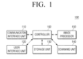
- FIG. 1 is a block diagram illustrating a configuration of an image scanning apparatus 100 according to an exemplary embodiment of the present invention.
- the image scanning apparatus 100 includes a communication interface unit 110, a user interface unit 120, a storage unit 130, a scanning unit 140, an image processor 150, and a controller 160.
- the image scanning apparatus may include a scanner, a copier, a facsimile, a multiple function peripheral (MFP) configured to multiply implement functions thereof through one apparatus.
- MFP multiple function peripheral
- the communication interface unit 110 may be connected to a host apparatus (not illustrated) such as a personal computer (PC), a laptop PC, a personal digital assistant (PDA), or a digital camera and transmit scanned data scanned in the image scanning apparatus 100 or a distortion-compensated scanned image from the image scanning apparatus 100 to the host apparatus (not illustrated).
- the communication interface unit 110 is formed to connect the image scanning apparatus 100 to an external apparatus.
- the communication interface unit 110 may be implemented to be connected to a terminal apparatus through a local area network (LAN) and an Internet network or through a universal serial bus (USB) port or a wireless port.
- LAN local area network
- USB universal serial bus
- the communication interface unit 110 may receive a scanning command.
- the communication interface unit 110 may receive the scanning command or a scanned image transmission command from the host apparatus.
- the scanning command may include a copying command or a facsimile transmission command required in a scanning function. That is, the communication interface unit 110 may receive a copying command or a facsimile transmission command. Even when the commands are received, a skew compensation process according to an exemplary embodiment may be performed.
- the user interface unit 120 may include a plurality of function keys configured to cause a user to set or select various functions supported in the image scanning apparatus 100 and display various pieces of information provided from the image scanning apparatus 100.
- the user interface unit 120 may be implemented with a device in which an input and an output are simultaneously implanted such as a touch screen or a device in which a mouse and a monitor are combined.
- the user interface unit 120 receives a job execution command.
- the user interface unit 120 may receive an execution command (for example, a scanning command, a copying command, a facsimile transmission command, and the like) for the functions to be executable in the image scanning apparatus 100.
- the user interface unit 120 may receive a selection of a skew compensation execution to be described later.
- the user interface unit 120 may receive a selection of a pre-scanning execution.
- the pre-scanning is a method of fast scanning an original document with a low resolution in advance before scanning the original document with a high resolution and may be used when a scanning region is designated.
- the user interface unit 120 may be implemented so that the skew compensation execution is selected by the user or the skew compensation is automatically executed without the selection of the user.
- the user interface unit 120 may display the scanned image.
- the user interface unit 120 may display a scanned image generated by a pre-scanning job in a preview and display a scanned image generated by a scanning job.
- the storage unit 130 may store the scanned image scanned in the image scanning apparatus 100.
- the storage unit 130 may store a scanned image compensated in the image processor 150 to be described later.
- the storage unit 130 may include a volatile memory.
- the storage unit 130 may include a volatile memory and a nonvolatile memory.
- the scanned image scanned or compensated as described above may be stored in the volatile memory (for example, a dynamic random access memory (DRAM)).
- DRAM dynamic random access memory
- the storage unit 130 may be implemented with a storage medium in the image scanning apparatus 100 and an external storage medium, for example, a removable disc including a USB memory, a storage medium connected to a host, a web server through a network, or the like.
- the scanning unit 140 scans an original document on a flatbed and generates a scanned image.
- the scanning unit 140 may include a stage glass on which the original document is loaded and a scanning head configured to reciprocally move below the stage glass and scan an original document.
- the canning unit 140 may be implemented to include an automatic providing apparatus and may scan the original document loaded on the automatic providing apparatus and automatically provided thereto.
- the scanning unit 140 may scan the original document one or more times.
- the scanning unit 140 may fast scan (pre-scan) the original document with a low resolution (first resolution) to generate a first scanned image having a low resolution and then secondarily scan the original document with a high resolution (second resolution) to generate a second scanned image.
- the first scanned image may be usable in the skew compensation execution of the image processor 150 according to a design or user preference. It is also possible that the second scanned image can be used in the skew compensation execution of the image processor 150 according to a design or user preference.
- the image processor 150 reads the generated scanned image in preset block units from the first scanned image or the second scanned image and performs image processing on the scanned image read in block units using a plurality of image processing modules (or blocks).
- the plurality of image processing modules may include a skew compensation module, a gamma correction module, a color correction module, an image segmentation module, and a filtering module, and the like.
- Each of the plurality of image processing module may separately include a buffer configured to store an image of block units.
- the controller 160 controls respective components in the image scanning apparatus 100.
- the controller 160 may control the scanning unit 140 to perform a scanning job and control the image processor 150 to perform compensation on a scanned image generated by the scanning job.
- the controller 160 may control the storage unit 130 to store the compensated scanned image in block units and control the communication interface 110 to transmit the stored scanned image to an external terminal apparatus (or a specific storage medium designated by the user). Although not illustrated in the exemplary embodiment, when the image scanning apparatus 100 is an MFP configured to perform a printing job, the controller 160 may control the compensated scanned image to be printed.
- the image scanning apparatus may perform compensation (for example, skew compensation) using the image processor having a small capacity of memory buffer. Further, the image scanning apparatus according to the exemplary embodiment may use a small capacity of memory buffer even when an image has a high resolution or a complicated interpolation method is used. The image scanning apparatus 100 according to the exemplary embodiment may collectively perform other image compensation in addition to the skew compensation using the plurality of image processing modules.
- the exemplary embodiment has illustrated that the image processor 150 and the controller 160 are separately configured from each other, but the image processor 150, the controller 160, and/or one or more other units may be implemented with one system on chip (SoC).
- SoC system on chip
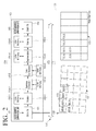
- FIG. 2 is a block diagram illustrating the image processor 150 of the image scanning apparatus 100 of FIG. 1 .
- the image processor 150 includes a reader 151, a first block address generation unit 152, a plurality of image processing modules 153, a plurality of buffers 154, a second block address generation unit 155, and a writer 156.
- the reader (DMA Rx) 150 may read a partial image 132 among first block units of the scanned image 131 stored in the storage unit 130 in a direct memory access (DMA) manner.
- the reader 151 may read a scanned image having a first block size (hereinafter, referred to as a scanned image block) corresponding to a block address provided from the first block address generation unit 152 to be described later from the storage unit 130 through a system bus 170.
- the reader 151 may transmit the read scanned image block 132 to the plurality of image processing modules 153. When the reading and transmitting of the first block 132 is completed, the reader 151 may perform reading on next block 133 overlapping the first block 132.
- the first block address generation unit 152 determines a size of the first block (that is, a first block size).
- the first block address generation unit 152 determines the first block size based on an effective pixel size to be processable in the plurality of image processing modules 153, a skew angle, and an interpolation method.
- the first block may include an effective pixel region having a second block size and a neighboring pixel region around the effective pixel region. Detailed description of determining the first block size will be described later with reference to FIG. 6 .
- the first block address generation unit 152 may divide the scanned image into a plurality of scanned image blocks overlapping each other and sequentially provide addresses of the divided scanned image blocks having the first block size to the reader 151.
- the first block address generation unit 152 may be implemented to provide the first block size described above and a reference coordinate of a block to be read to the reader 151.
- the first block address generation unit 152 calculates a coordinate value having an integer value closest thereto after a position corresponding to a left corner of the first block is rotated by Equation 1.
- the first block address generation unit 152 may select the block size by considering neighboring pixels (that is, neighboring pixels) required to perform the interpolation.
- Each of the plurality of image processing modules 153 may be separately connected to corresponding one of the plurality of buffers 154 and performs image processing using the corresponding buffer connected thereto.
- the plurality of image processing modules 153 may include a skew compensation module 153-1, a gamma correction module 153-2, a color correction module 153-3, an image segmentation module 153-4, and a filtering module 153-5.
- the skew compensation module 153-1 may be referred to as a rotator.
- the exemplary embodiment has described that the plurality of image processing modules are five, but the plurality of image processing modules may be implemented to include only two or five or to include six modules or more including an additional module addition to the above-described modules.
- the exemplary embodiment has illustrated and described that the image processing modules perform operations such as a gamma correction operation and a color correction operation after the performing of the skew compensation, but the plurality of image processing modules may be implemented to perform the gamma correction and color correction before the performing of the skew compensation.
- the skew compensation module 153-1 is connected to a first buffer 154-1 and stores the scanned image block provided from the reader 151 in the first buffer 154-1.
- the skew compensation module 153-1 may sense a skew angle of the scanned image.
- the exemplary embodiment has described that the skew compensation module 153-1 checks whether or not the skew is present and senses the skew angle, but it may be implemented that the first block address generation unit 152 or other separate modules checks whether or not the skew is present and sense the skew angle.
- the skew compensation module 153-1 compensates the sensed skew angle of the scanned image block stored in the first buffer 154-1. A detailed configuration and operation of the skew compensation module 153-1 will be described later with reference to FIG. 4 .
- the gamma correction module 153-2 is connected to a second buffer 154-2 configured to store a gamma table and performs linear correction on the scanned image block provided from the skew compensation module 153-1. Specifically, the gamma correction module 153-2 may linearly correct unique gamma function type distortion characteristic of the image sensor using the gamma table stored in the second buffer 154-2.
- the gamma correction module 153-2 may correct a brightness value difference with respect to the skew-compensated image block.
- the gamma correction module 153-2 may correct shading which means the difference of the bright value generated when light is not uniformly formed with respect to a main radiation direction of an image by a light source. It may be implemented that the shading correction is performed before the gamma correction is performed in the gamma correction module 153-2.
- the color correction module 153-3 is connected to a third buffer 154-3 configured to store a color correction table and perform color correction on the scanned image block provided from the gamma correction module 153-2.
- the image segmentation module 153-4 is connected to a fourth buffer 154-4 and stores the scanned image block provided from the color correction module 153-3 in the fourth buffer 154-4.
- the image segmentation module 153-4 may remove an unnecessary portion (for example, a neighboring pixel region) from the scanned image block stored in the fourth buffer 154-4.
- the image is processed in the first block size including the effective pixel region having the second block size and a neighboring pixel region around the effective pixel region. Therefore, the image segmentation module 153-4 may remove the unnecessary neighboring pixel region from the image block of the first block size and output a removing result.
- the filtering module 153-5 is connected to a fifth buffer 153-5 and stores the scanned image block provided from the image segmentation module 154-5.
- the filtering module 154-5 performs on filtering processing on the image-segmented image block.
- the second block address generation unit 155 generates addresses of the storage unit 130 in which the scanned image blocks image-processed in the plurality of image processing modules are to be stored.
- the exemplary embodiment has described that the second block address generation unit 155 generates the addresses of the storage unit 130, but it may be implemented that the storage addresses of the image-processed scanned image blocks are generated in the first block address generation unit 152 and the generated addresses are provided to the second block address generation unit 155.
- the writer 156 may store the image blocks processed in the plurality of image processing modules in a preset region 135 of the storage unit 130 through the system bus 170 based on the addresses generated in the second block address generation unit 155.
- FIG. 3 is a view illustrating skew sensing and skew compensation.
- the image processor 150 senses whether a skew is generated from a top boundary of a printing paper.
- the image processor 150 may calculate a specific skew angle.
- the methods of calculating the skew angle have been widely known and thus detailed description thereof will be omitted.
- a printing medium is tilted by an angle ⁇ ' to the left.
- the image processor 150 may detect the tilted angle as the skew angle.
- FIG. 4 is a view explaining an operation of the skew compensation module of FIG. 2 .
- the skew compensation module 153-1 or 200 may rotate the read scanned image block by an angle ⁇ in a clockwise direction or counterclockwise direction with respect to a center portion disposed around (x c , y c ) as in Equation 1 and obtain a target image.
- the skew compensation module 200 may compensate for the skew by rotating the source image by the angle ⁇ to the counterclockwise direction.
- the source image and the target image are configured of coordinates having integer values and the pixel value corresponding to each of the coordinates may be generally represented in a digital value having 256 gradations of o to 255.
- the skew compensation module 200 After the skew compensation module 200 receives an image 500 on which the skew compensation is not performed and performs the skew compensation, the skew compensation module 200 outputs the skew-compensated scanned image block 530. As illustrated in FIG. 4 , for the other image processing modules of the next stages, the skew-compensated scanned image has overlapping data (an outer region 530 of a region 540).
- the skew compensation block 200 may include a buffer controller 210, a position generation unit 220, and an interpolation unit 230.
- the buffer controller 210 receives a scanned image block and stores the received scanned image block in the first buffer 154-1.
- the buffer controller 210 performs a function to read data required in the interpolation unit 230 and provide the read data to the interpolation unit 230.
- the position generation unit 220 generates an address from which the date required in the interpolation unit 230 is to be read.
- the interpolation unit 230 performs interpolation on the effective pixel region using the neighboring pixel region. Specifically, the interpolation unit 230 performs the interpolation using neighboring pixel values of the effective pixel region to calculate the pixel value of the target.
- the interpolation unit 230 may perform the interpolation using a bilinear interpolation method or a quadratic interpolation method. The interpolation method will be described later with reference to FIG. 5 .
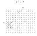
- FIG. 5 is a view illustrating an interpolation operation according to an exemplary embodiment of the present invention.
- a coordinate 601 in which P 1 (x 1 , y 1 ) is rotated becomes a coordinate P 2 (x 2 , y 2 ) 602.
- P 2 has a real value, but a pixel value corresponding to P 2 is not existed. Therefore, the interpolation unit 230 may perform the interpolation using pixel values a11 to a33 around the coordinate P 2 .
- the interpolation may be performed using four values, that is, a11, a12, a21, and a22 when a bilinear interpolation is used, while the interpolation may be performed using nine values, that is, a11 to a33 when a quadratic interpolation method is used.
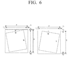
- FIG. 6 is a view illustrating a block size according to an exemplary embodiment of the present invention.
- FIG. 6 is an enlarged view illustrating a region of a source image corresponding to a target block and a region including neighboring pixels.
- the size of the block read from the scanned image may be calculated according to the following Equation 2.
- P M x cos ⁇ + N x sin ⁇ + T l + T r
- Q M x sin ⁇ + N x cos ⁇ + T u + T d
- ⁇ is a skew angle
- P is a horizontal length of a first block
- Q is a vertical length of the first block
- M is a horizontal length of second block (an effective pixel)
- N is a vertical length of the second block (effective pixel)
- each of T 1 , T r , T u , and T d is the number of neighboring pixels required for interpolation.
- a horizontal length P 2 of the memory buffer is equal to P and a vertical length Q thereof as follows.
- the first block size is calculated so that the effective pixel region does not overlap neighboring blocks, but the first block size may be calculated so that the second blocks overlap each other.
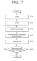
- FIG. 7 is a flowchart illustrating an image processing method according to an exemplary embodiment of the present invention.
- image scanning apparatus scans an original document and generates a scanned image at operation S710.
- the image processing apparatus stores the generated scanned image in the storage unit at operation S720.
- the scanned image scanned in the scanning unit may be stored in a preset region of the memory.
- the image scanning apparatus reads the generated scanned image in preset block units at operation S730.
- the operation of reading in preset block units will be described later with reference to FIG. 8 .
- the image scanning apparatus performs image processing on the scanned image read in block units sequentially using the plurality of image processing modules which separately include the buffers configured to the scanned images of block units at operation S740.
- the image scanning apparatus may preferentially perform skew compensation on the scanned image read in block units using the skew compensation module and then sequentially perform other image processing on the skew-compensated scanned image of block units.
- the plurality of image processing operations using the plurality of image processing modules have been described in advance with reference to FIG. 2 and detailed description thereof will be omitted.
- the image scanning apparatus stores the image-processed scanned image of block units at operation S750.
- the image scanning apparatus may store the image-processed scanned image of block units in a preset region of the memory corresponding to a position of the block.
- the image scanning apparatus determines whether or not the image processing is performed on all blocks at operation S760. When it is determined that the image processing is not performed on all the blocks, the image scanning apparatus repeatedly perform operations S730, S740, and S750 as described above on blocks on which image processing are not performed at operation S760.
- the image compensation method may perform compensation (for example, skew compensation) using the image processor having a small capacity of memory buffer. Further, even when an image has high resolution or a complicate interpolation method is used, the small capacity of memory may be used.
- the image concentration method uses a plurality of image processing modules to collectively perform skew compensation and other image compensation.
- the image concentration method as illustrated in FIG. 7 may be executed on the image scanning apparatus having the configuration of FIG. 1 and further executed on image scanning apparatuses having other configurations.
- the above-described image compensation method may be implemented with a program (application) including an algorithm to be executable in a computer and the program may be stored and provided in a non-transitory computer-readable medium.
- a program application
- the program may be stored and provided in a non-transitory computer-readable medium.
- the non-transitory computer-recordable medium is not a medium configured to temporarily store data such as a register, a cache, a memory, and the like but an apparatus-readable medium configured to semi-permanently store data.
- the above-described applications or programs may be stored and provided in the non-transitory computer-recordable medium such as a compact disc (CD), a digital versatile disc (DVD), a hard disc (HD), a blu-ray disc, a USB, a memory card, a read only memory (ROM), and the like.
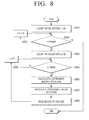
- FIG. 8 is a flowchart illustrating the read operation S730 of the method of FIG. 7 .
- the image processor initializes a first count value i at operation S810.
- the image processor determines whether or not the first count value is smaller than a height at operation S820 and the image processor initializes a second counter value j when it is determined that the first counter value is smaller than the height at operation S830.
- the image processor determines whether or not the second counter value is smaller than a width at operation S840. When it is determined that the second counter value is larger than the width at operation S840-N, the image processor adds the vertical length (Q) of the first block to the first counter value at operation S850 and performs the operation S820 again.
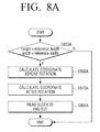
- the image processor calculates a coordinates before rotation (S860) and then calculates a coordinate after the rotation at operation S870.
- the image processor reads a block of a PxQ size from the scanned image at operation S880.
- the image processor adds a horizontal length (P) of the first block to the second counter value at operation S890 and performs the operation S840 again.
Landscapes
- Engineering & Computer Science (AREA)
- Multimedia (AREA)
- Signal Processing (AREA)
- Physics & Mathematics (AREA)
- General Physics & Mathematics (AREA)
- Theoretical Computer Science (AREA)
- Image Processing (AREA)
- Editing Of Facsimile Originals (AREA)
- Facsimile Scanning Arrangements (AREA)
Abstract
Description
- The present invention relates to an image scanning apparatus, an image compensation method, and a computer-readable recording medium, and more particularly, to an image scanning apparatus capable of reading a scanned image in block units and compensating the scanned image using a low capacity of buffer, an image compensation method, and a computer-readable recording medium.
- In general, image scanning apparatuses are apparatuses which scan original images such as texts, pictures, or films and convert the scanned image into digital data. The digital data may be displayed on a monitor of a computer or printed by the printer and generated as an output image. As an example of the image scanning apparatuses, there are scanners, copiers, facsimiles, multiple function peripherals (MFPs) configured to multiply implement functions thereof through one apparatus.
- In the image scanning apparatuses, a paper may be twistedly input due to mechanical characteristics and thus a skew in which the scanned image is rotated may caused. Since an image undesired by a user is scanned or copied and the user feels uncomfortable when the image is rotated, current image scanning apparatuses have the skew compensation function.
- Specifically, the skew may be compensated through an operation using the following
Equation 1.
- Here, θ is a rotation angle, x is a position in a column direction, y is a position in a row direction, (xc, yc) is a center point, (x1, y1) is a source position, and (x2, y2) is a target position.
- A coordinate (x2, y2) position-adjusted through
Equation 1 described above may have a real value. A pixel value corresponding an integer value of the coordinate (x2, y2) having the real value may be obtain through interpolation using neighboring pixel values of a source image. - However, it is ineffective when a required pixel is read from a main memory, in which the source image is stored, to calculate a target pixel in terms of a bandwidth of a bus. In the related art, to solve the issue, a line memory buffer is included and used to store a small amount of line data of the source image. For example, in A4-size paper of 600 dot per inch (DPI), data of about 5 Kbyte is necessary with respect to one line per mono one channel.
- However, when the skew is compensated as described above, the capacity of the line memory buffer has to be increased according to a skew angle. For example, the image is rotated in an angle range of -1 degree to 1 degree, the line memory buffer needs 60 lines. The number of pixels necessary for an operation is increased according to complexity of the interpolation and the capacity of the line memory buffer has to be increased as the resolution of an image to be processed is increased.
- One or more exemplary embodiments are to provide an image scanning apparatus capable of reading a scanned image in block units and compensating the scanned image using a low capacity of buffer, an image compensation method, and a computer-readable recording medium.
- Additional features and utilities of the present invention will be set forth in part in the description which follows and, in part, will be obvious from the description, or may be learned by practice of the invention.
- The foregoing and/or other features and utilities of the present invention may be achieved by providing an image scanning apparatus. The image scanning apparatus may include a scanning unit configured to scan an original document and generate a scanned image, a storage unit configured to store the generated scanned image, an image processor including a plurality of image processing modules, the plurality of image processing modules separately including a plurality of buffers configured to store the scanned image of block units, and configured to read the generated scanned image in preset block units and perform image processing on the scanned image read in block units sequentially using the plurality of image processing modules, and a controller configured to store the image-processed scanned image in the storage unit.
- The plurality of image processing module may be connected in series and each of the plurality of image processing modules may be connected to one of the plurality of buffers configured to store the scanned image of block units.
- The image processing modules may include at least one of a skew compensation module, a gamma correction module, a color correction module, an image segmentation module, and a filtering module.
- The image processor may read the scanned image in a first block size including an effective pixel region having a second block size and a neighboring pixel region around the effective pixel region.
- The image processor may read the scanned image so that a plurality of scanned image blocks having the first block size overlap each other.
- The image processor may determine the first block size based on an effective pixel size to be processable in the plurality of image processing modules, a skew angle, and an interpolation method.
- The image processing module may include a skew compensation modules configured to sense the skew angle of the scanned image and compensate for the sensed skew angle.
- The skew compensation module may perform interpolation on the effective pixel region using the neighboring pixel region and output a compensated scanned image block corresponding to the effective pixel region.
- The interpolation may be performed using at least one of a bilinear interpolation method and a quadratic interpolation method.
- The image processor may read the generated scanned image from the storage unit in a direct memory access (DMA) manner.
- The image processor may be a system on chip (SoC).
- The foregoing and/or other features and utilities of the present invention may also be achieved by providing an image compensation method of an image scanning apparatus. The method may include scanning an original document to generate a scanned image, storing the generated scanned image, reading the generated scanned image in preset block units, performing image processing on the scanned image read in block units sequentially using a plurality of image processing modules separately including a plurality of buffers configured to store the scanned image of block units, and storing the image-processed scanned image.
- The reading may include reading the scanned image including an effective pixel region having a second block size and a neighboring pixel region around the effective pixel region in a first block size.
- The reading may include reading the scanned image so that a plurality of scanned image blocks having the first block size overlap each other.
- The reading may include determining the first block size based on an effective pixel size to be processable in the plurality of image processing modules, a skew angle, and an interpolation method and reading the scanned image in the determined first block size.
- The performing image processing may include sensing the skew angle of the scanned image and compensating for the sensed skew angle.
- The performing image processing may include performing interpolation on the effective pixel region using the neighboring pixel region and outputting an interpolated scanned image block corresponding to the effective pixel region.
- The performing interpolation may include performing the interpolation using at least one of a bilinear interpolation method and a quadratic interpolation method.
- The performing image processing may include performing image processing including at least two of skew compensation, gamma correction, color correction, image segmentation, and filtering on the scanned image.
- The reading may include reading the generated scanned image from a storage unit in a direct memory access (DMA) manner.
- The foregoing and/or other features and utilities of the present invention may also be achieved by providing a computer-readable recording medium including a program to execute an image compensation method. The image compensation method may include scanning an original document to generate a scanned image, storing the generated scanned image, reading the generated scanned image in preset block units, performing image processing on the scanned image read in block units sequentially using a plurality of image processing modules separately including a plurality of buffers configured to store the scanned image of block units, and storing the image-processed scanned image.
- The foregoing and/or other features and utilities of the present invention may also be achieved by providing an image scanning apparatus, including a scanning unit configured to scan an original document and generate a scanned image, a storage unit configured to store the generated scanned image, and an image processor including a plurality of image processing modules connected to a plurality of buffers to store data processed in the corresponding image processing modules, and configured to read the generated scanned image in the block units and sequentially perform image processing on the scanned image read in block units using the plurality of image processing modules, the image processing including a skew compensation and at least one of Gamma correction and color correction, and segmentation.
- These and/or other features and utilities of the present invention will become apparent and more readily appreciated from the following description of the embodiments, taken in conjunction with the accompanying drawings of which:
-
FIG. 1 is a block diagram illustrating an image scanning apparatus according to an exemplary embodiment of the present invention; -
FIG. 2 is a block diagram illustrating an image processor of the image scanning apparatus ofFIG. 1 ; -
FIG. 3 is a view explaining skew compensation; -
FIG. 4 is a view explaining an operation of a skew compensation module ofFIG. 2 ; -
FIG. 5 is a view explaining an interpolation operation according to an exemplary embodiment of the present invention; -
FIG. 6 is a view explaining a block size according to an exemplary embodiment of the present invention; -
FIG. 7 is a flow chart illustrating an image processing method according to an exemplary embodiment of the present invention; and -
FIG. 8 is a flowchart illustrating a read operation of the method ofFIG. 7 . - Hereinafter, exemplary embodiments will be described in more detail with reference to the accompanying drawings.
- Reference will now be made in detail to the embodiments of the present invention, examples of which are illustrated in the accompanying drawings, wherein like reference numerals refer to the like elements throughout. The embodiments are described below in order to explain the present invention while referring to the figures.
- In the following description, the matters defined in the description, such as detailed construction and elements, are provided to assist in a comprehensive understanding of the exemplary embodiments. Thus, it is apparent that the exemplary embodiments can be carried out without those specifically defined matters. Also, functions or elements known in the related art are not described in detail since they would obscure the exemplary embodiments with unnecessary detail.
-
FIG. 1 is a block diagram illustrating a configuration of animage scanning apparatus 100 according to an exemplary embodiment of the present invention. - Referring to
FIG. 1 , theimage scanning apparatus 100 according to an exemplary embodiment includes acommunication interface unit 110, auser interface unit 120, astorage unit 130, ascanning unit 140, animage processor 150, and acontroller 160. The image scanning apparatus may include a scanner, a copier, a facsimile, a multiple function peripheral (MFP) configured to multiply implement functions thereof through one apparatus. - The
communication interface unit 110 may be connected to a host apparatus (not illustrated) such as a personal computer (PC), a laptop PC, a personal digital assistant (PDA), or a digital camera and transmit scanned data scanned in theimage scanning apparatus 100 or a distortion-compensated scanned image from theimage scanning apparatus 100 to the host apparatus (not illustrated). Thecommunication interface unit 110 is formed to connect theimage scanning apparatus 100 to an external apparatus. Thecommunication interface unit 110 may be implemented to be connected to a terminal apparatus through a local area network (LAN) and an Internet network or through a universal serial bus (USB) port or a wireless port. - The
communication interface unit 110 may receive a scanning command. Thecommunication interface unit 110 may receive the scanning command or a scanned image transmission command from the host apparatus. The scanning command may include a copying command or a facsimile transmission command required in a scanning function. That is, thecommunication interface unit 110 may receive a copying command or a facsimile transmission command. Even when the commands are received, a skew compensation process according to an exemplary embodiment may be performed. - The
user interface unit 120 may include a plurality of function keys configured to cause a user to set or select various functions supported in theimage scanning apparatus 100 and display various pieces of information provided from theimage scanning apparatus 100. Theuser interface unit 120 may be implemented with a device in which an input and an output are simultaneously implanted such as a touch screen or a device in which a mouse and a monitor are combined. - The
user interface unit 120 receives a job execution command. Theuser interface unit 120 may receive an execution command (for example, a scanning command, a copying command, a facsimile transmission command, and the like) for the functions to be executable in theimage scanning apparatus 100. At this time, theuser interface unit 120 may receive a selection of a skew compensation execution to be described later. Theuser interface unit 120 may receive a selection of a pre-scanning execution. Here, the pre-scanning is a method of fast scanning an original document with a low resolution in advance before scanning the original document with a high resolution and may be used when a scanning region is designated. On the other hand, theuser interface unit 120 may be implemented so that the skew compensation execution is selected by the user or the skew compensation is automatically executed without the selection of the user. - The
user interface unit 120 may display the scanned image. Theuser interface unit 120 may display a scanned image generated by a pre-scanning job in a preview and display a scanned image generated by a scanning job. - The
storage unit 130 may store the scanned image scanned in theimage scanning apparatus 100. Thestorage unit 130 may store a scanned image compensated in theimage processor 150 to be described later. Thestorage unit 130 may include a volatile memory. Alternatively, thestorage unit 130 may include a volatile memory and a nonvolatile memory. At this time, the scanned image scanned or compensated as described above may be stored in the volatile memory (for example, a dynamic random access memory (DRAM)). - The
storage unit 130 may be implemented with a storage medium in theimage scanning apparatus 100 and an external storage medium, for example, a removable disc including a USB memory, a storage medium connected to a host, a web server through a network, or the like. - The
scanning unit 140 scans an original document on a flatbed and generates a scanned image. Thescanning unit 140 may include a stage glass on which the original document is loaded and a scanning head configured to reciprocally move below the stage glass and scan an original document. Thecanning unit 140 may be implemented to include an automatic providing apparatus and may scan the original document loaded on the automatic providing apparatus and automatically provided thereto. - The
scanning unit 140 may scan the original document one or more times. Thescanning unit 140 may fast scan (pre-scan) the original document with a low resolution (first resolution) to generate a first scanned image having a low resolution and then secondarily scan the original document with a high resolution (second resolution) to generate a second scanned image. The first scanned image may be usable in the skew compensation execution of theimage processor 150 according to a design or user preference. It is also possible that the second scanned image can be used in the skew compensation execution of theimage processor 150 according to a design or user preference. - The
image processor 150 reads the generated scanned image in preset block units from the first scanned image or the second scanned image and performs image processing on the scanned image read in block units using a plurality of image processing modules (or blocks). Here, the plurality of image processing modules may include a skew compensation module, a gamma correction module, a color correction module, an image segmentation module, and a filtering module, and the like. Each of the plurality of image processing module may separately include a buffer configured to store an image of block units. - Detailed configuration and operation of the
image processor 150 will be described later with reference toFIG. 2 . - The
controller 160 controls respective components in theimage scanning apparatus 100. When thecontroller 160 receives a scanning command from theuser interface unit 120 or thecommunication unit 110, thecontroller 160 may control thescanning unit 140 to perform a scanning job and control theimage processor 150 to perform compensation on a scanned image generated by the scanning job. - The
controller 160 may control thestorage unit 130 to store the compensated scanned image in block units and control thecommunication interface 110 to transmit the stored scanned image to an external terminal apparatus (or a specific storage medium designated by the user). Although not illustrated in the exemplary embodiment, when theimage scanning apparatus 100 is an MFP configured to perform a printing job, thecontroller 160 may control the compensated scanned image to be printed. - The image scanning apparatus according to the exemplary embodiment may perform compensation (for example, skew compensation) using the image processor having a small capacity of memory buffer. Further, the image scanning apparatus according to the exemplary embodiment may use a small capacity of memory buffer even when an image has a high resolution or a complicated interpolation method is used. The
image scanning apparatus 100 according to the exemplary embodiment may collectively perform other image compensation in addition to the skew compensation using the plurality of image processing modules. - The exemplary embodiment has illustrated that the
image processor 150 and thecontroller 160 are separately configured from each other, but theimage processor 150, thecontroller 160, and/or one or more other units may be implemented with one system on chip (SoC). -
FIG. 2 is a block diagram illustrating theimage processor 150 of theimage scanning apparatus 100 ofFIG. 1 . - Referring to
FIG. 2 , theimage processor 150 includes areader 151, a first blockaddress generation unit 152, a plurality ofimage processing modules 153, a plurality ofbuffers 154, a second blockaddress generation unit 155, and awriter 156. - The reader (DMA Rx) 150 may read a
partial image 132 among first block units of the scannedimage 131 stored in thestorage unit 130 in a direct memory access (DMA) manner. Thereader 151 may read a scanned image having a first block size (hereinafter, referred to as a scanned image block) corresponding to a block address provided from the first blockaddress generation unit 152 to be described later from thestorage unit 130 through asystem bus 170. Thereader 151 may transmit the read scannedimage block 132 to the plurality ofimage processing modules 153. When the reading and transmitting of thefirst block 132 is completed, thereader 151 may perform reading onnext block 133 overlapping thefirst block 132. - The first block
address generation unit 152 determines a size of the first block (that is, a first block size). The first blockaddress generation unit 152 determines the first block size based on an effective pixel size to be processable in the plurality ofimage processing modules 153, a skew angle, and an interpolation method. The first block may include an effective pixel region having a second block size and a neighboring pixel region around the effective pixel region. Detailed description of determining the first block size will be described later with reference toFIG. 6 . - The first block
address generation unit 152 may divide the scanned image into a plurality of scanned image blocks overlapping each other and sequentially provide addresses of the divided scanned image blocks having the first block size to thereader 151. The first blockaddress generation unit 152 may be implemented to provide the first block size described above and a reference coordinate of a block to be read to thereader 151. For example, the first blockaddress generation unit 152 calculates a coordinate value having an integer value closest thereto after a position corresponding to a left corner of the first block is rotated byEquation 1. The first blockaddress generation unit 152 may select the block size by considering neighboring pixels (that is, neighboring pixels) required to perform the interpolation. - Each of the plurality of
image processing modules 153 may be separately connected to corresponding one of the plurality ofbuffers 154 and performs image processing using the corresponding buffer connected thereto. Here, the plurality ofimage processing modules 153 may include a skew compensation module 153-1, a gamma correction module 153-2, a color correction module 153-3, an image segmentation module 153-4, and a filtering module 153-5. The skew compensation module 153-1 may be referred to as a rotator. The exemplary embodiment has described that the plurality of image processing modules are five, but the plurality of image processing modules may be implemented to include only two or five or to include six modules or more including an additional module addition to the above-described modules. The exemplary embodiment has illustrated and described that the image processing modules perform operations such as a gamma correction operation and a color correction operation after the performing of the skew compensation, but the plurality of image processing modules may be implemented to perform the gamma correction and color correction before the performing of the skew compensation. - The skew compensation module 153-1 is connected to a first buffer 154-1 and stores the scanned image block provided from the
reader 151 in the first buffer 154-1. The skew compensation module 153-1 may sense a skew angle of the scanned image. The exemplary embodiment has described that the skew compensation module 153-1 checks whether or not the skew is present and senses the skew angle, but it may be implemented that the first blockaddress generation unit 152 or other separate modules checks whether or not the skew is present and sense the skew angle. - The skew compensation module 153-1 compensates the sensed skew angle of the scanned image block stored in the first buffer 154-1. A detailed configuration and operation of the skew compensation module 153-1 will be described later with reference to
FIG. 4 . - The gamma correction module 153-2 is connected to a second buffer 154-2 configured to store a gamma table and performs linear correction on the scanned image block provided from the skew compensation module 153-1. Specifically, the gamma correction module 153-2 may linearly correct unique gamma function type distortion characteristic of the image sensor using the gamma table stored in the second buffer 154-2.
- The gamma correction module 153-2 may correct a brightness value difference with respect to the skew-compensated image block. The gamma correction module 153-2 may correct shading which means the difference of the bright value generated when light is not uniformly formed with respect to a main radiation direction of an image by a light source. It may be implemented that the shading correction is performed before the gamma correction is performed in the gamma correction module 153-2.
- The color correction module 153-3 is connected to a third buffer 154-3 configured to store a color correction table and perform color correction on the scanned image block provided from the gamma correction module 153-2.
- The image segmentation module 153-4 is connected to a fourth buffer 154-4 and stores the scanned image block provided from the color correction module 153-3 in the fourth buffer 154-4. The image segmentation module 153-4 may remove an unnecessary portion (for example, a neighboring pixel region) from the scanned image block stored in the fourth buffer 154-4. In the above-described exemplary embodiment, the image is processed in the first block size including the effective pixel region having the second block size and a neighboring pixel region around the effective pixel region. Therefore, the image segmentation module 153-4 may remove the unnecessary neighboring pixel region from the image block of the first block size and output a removing result.
- The filtering module 153-5 is connected to a fifth buffer 153-5 and stores the scanned image block provided from the image segmentation module 154-5. The filtering module 154-5 performs on filtering processing on the image-segmented image block.
- The second block
address generation unit 155 generates addresses of thestorage unit 130 in which the scanned image blocks image-processed in the plurality of image processing modules are to be stored. The exemplary embodiment has described that the second blockaddress generation unit 155 generates the addresses of thestorage unit 130, but it may be implemented that the storage addresses of the image-processed scanned image blocks are generated in the first blockaddress generation unit 152 and the generated addresses are provided to the second blockaddress generation unit 155. - The
writer 156 may store the image blocks processed in the plurality of image processing modules in apreset region 135 of thestorage unit 130 through thesystem bus 170 based on the addresses generated in the second blockaddress generation unit 155. -
FIG. 3 is a view illustrating skew sensing and skew compensation. - Referring to
FIG. 3 , when the original document is fed, theimage processor 150 senses whether a skew is generated from a top boundary of a printing paper. - When it is determined whether the skew is generated, the
image processor 150 may calculate a specific skew angle. The methods of calculating the skew angle have been widely known and thus detailed description thereof will be omitted. - It can be seen from
FIG. 3 that a printing medium is tilted by an angle θ' to the left. When the printing medium is tilted to the left or to the right, theimage processor 150 may detect the tilted angle as the skew angle. -
FIG. 4 is a view explaining an operation of the skew compensation module ofFIG. 2 . - Referring to
FIG. 4 , the skew compensation module 153-1 or 200 may rotate the read scanned image block by an angle θ in a clockwise direction or counterclockwise direction with respect to a center portion disposed around (xc, yc) as inEquation 1 and obtain a target image. In the exemplary embodiment, since the source image is rotated by the angle θ to a clockwise direction, theskew compensation module 200 may compensate for the skew by rotating the source image by the angle θ to the counterclockwise direction. - On the other hand, in a digital image, the source image and the target image are configured of coordinates having integer values and the pixel value corresponding to each of the coordinates may be generally represented in a digital value having 256 gradations of o to 255.
- Therefore, after the
skew compensation module 200 receives animage 500 on which the skew compensation is not performed and performs the skew compensation, theskew compensation module 200 outputs the skew-compensated scannedimage block 530. As illustrated inFIG. 4 , for the other image processing modules of the next stages, the skew-compensated scanned image has overlapping data (anouter region 530 of a region 540). - As illustrated in
FIG. 4 , theskew compensation block 200 may include abuffer controller 210, aposition generation unit 220, and aninterpolation unit 230. - The
buffer controller 210 receives a scanned image block and stores the received scanned image block in the first buffer 154-1. Thebuffer controller 210 performs a function to read data required in theinterpolation unit 230 and provide the read data to theinterpolation unit 230. - The
position generation unit 220 generates an address from which the date required in theinterpolation unit 230 is to be read. - The
interpolation unit 230 performs interpolation on the effective pixel region using the neighboring pixel region. Specifically, theinterpolation unit 230 performs the interpolation using neighboring pixel values of the effective pixel region to calculate the pixel value of the target. Theinterpolation unit 230 may perform the interpolation using a bilinear interpolation method or a quadratic interpolation method. The interpolation method will be described later with reference toFIG. 5 . -
FIG. 5 is a view illustrating an interpolation operation according to an exemplary embodiment of the present invention. - Referring to
FIG. 5 , a coordinate 601 in which P1(x1, y1) is rotated becomes a coordinate P2 (x2, y2) 602. However, as illustrated inFIG. 5 , P2 has a real value, but a pixel value corresponding to P2 is not existed. Therefore, theinterpolation unit 230 may perform the interpolation using pixel values a11 to a33 around the coordinate P2. For example, the interpolation may be performed using four values, that is, a11, a12, a21, and a22 when a bilinear interpolation is used, while the interpolation may be performed using nine values, that is, a11 to a33 when a quadratic interpolation method is used. - Since the used neighboring pixel positions are different according to the interpolation method, the size of the first bock is changed according to the interpolation method.
FIG. 6 is a view illustrating a block size according to an exemplary embodiment of the present invention.FIG. 6 is an enlarged view illustrating a region of a source image corresponding to a target block and a region including neighboring pixels. - Referring to 6, the size of the block read from the scanned image may be calculated according to the following Equation 2.

- Here, θ is a skew angle, P is a horizontal length of a first block, Q is a vertical length of the first block, M is a horizontal length of second block (an effective pixel), N is a vertical length of the second block (effective pixel), and each of T1, Tr, Tu, and Td is the number of neighboring pixels required for interpolation. Specifically, (T1+Tr)=2 and (Tu+Td)=2 when the interpolation is a bilinear interpolation method, while (T1+Tr)=3 and (Tu+Td)=3 when the interpolation method is a quadratic interpolation method.
- A horizontal length P2 of the memory buffer is equal to P and a vertical length Q thereof as follows.


- It has been described that the first block size is calculated so that the effective pixel region does not overlap neighboring blocks, but the first block size may be calculated so that the second blocks overlap each other.
-
FIG. 7 is a flowchart illustrating an image processing method according to an exemplary embodiment of the present invention. - Referring to
FIG. 7 , first, image scanning apparatus scans an original document and generates a scanned image at operation S710. - The image processing apparatus stores the generated scanned image in the storage unit at operation S720. The scanned image scanned in the scanning unit may be stored in a preset region of the memory.
- The image scanning apparatus reads the generated scanned image in preset block units at operation S730. The operation of reading in preset block units will be described later with reference to
FIG. 8 . - The image scanning apparatus performs image processing on the scanned image read in block units sequentially using the plurality of image processing modules which separately include the buffers configured to the scanned images of block units at operation S740. The image scanning apparatus may preferentially perform skew compensation on the scanned image read in block units using the skew compensation module and then sequentially perform other image processing on the skew-compensated scanned image of block units. The plurality of image processing operations using the plurality of image processing modules have been described in advance with reference to
FIG. 2 and detailed description thereof will be omitted. - The image scanning apparatus stores the image-processed scanned image of block units at operation S750. The image scanning apparatus may store the image-processed scanned image of block units in a preset region of the memory corresponding to a position of the block.
- The image scanning apparatus determines whether or not the image processing is performed on all blocks at operation S760. When it is determined that the image processing is not performed on all the blocks, the image scanning apparatus repeatedly perform operations S730, S740, and S750 as described above on blocks on which image processing are not performed at operation S760.
- The image compensation method according to the above-described exemplary embodiment may perform compensation (for example, skew compensation) using the image processor having a small capacity of memory buffer. Further, even when an image has high resolution or a complicate interpolation method is used, the small capacity of memory may be used. The image concentration method according to an exemplary embodiment uses a plurality of image processing modules to collectively perform skew compensation and other image compensation. The image concentration method as illustrated in
FIG. 7 may be executed on the image scanning apparatus having the configuration ofFIG. 1 and further executed on image scanning apparatuses having other configurations. - The above-described image compensation method may be implemented with a program (application) including an algorithm to be executable in a computer and the program may be stored and provided in a non-transitory computer-readable medium.
- The non-transitory computer-recordable medium is not a medium configured to temporarily store data such as a register, a cache, a memory, and the like but an apparatus-readable medium configured to semi-permanently store data. Specifically, the above-described applications or programs may be stored and provided in the non-transitory computer-recordable medium such as a compact disc (CD), a digital versatile disc (DVD), a hard disc (HD), a blu-ray disc, a USB, a memory card, a read only memory (ROM), and the like.
-
FIG. 8 is a flowchart illustrating the read operation S730 of the method ofFIG. 7 . - Referring to
FIG. 8 , first, the image processor initializes a first count value i at operation S810. - The image processor determines whether or not the first count value is smaller than a height at operation S820 and the image processor initializes a second counter value j when it is determined that the first counter value is smaller than the height at operation S830.
- The image processor determines whether or not the second counter value is smaller than a width at operation S840. When it is determined that the second counter value is larger than the width at operation S840-N, the image processor adds the vertical length (Q) of the first block to the first counter value at operation S850 and performs the operation S820 again.
- When it is determined that the second counter value is smaller than the width at operation S840-Y, the image processor calculates a coordinates before rotation (S860) and then calculates a coordinate after the rotation at operation S870.
- The image processor reads a block of a PxQ size from the scanned image at operation S880. The image processor adds a horizontal length (P) of the first block to the second counter value at operation S890 and performs the operation S840 again.
- Although a few embodiments of the present invention have been shown and described, it will be appreciated by those skilled in the art that changes may be made in these embodiments without departing from the invention, the scope of which is defined in the appended claims.
Claims (15)
- An image scanning apparatus, comprising:a scanning unit configured to scan an original document and generate a scanned image;a storage unit configured to store the generated scanned image;an image processor including a plurality of image processing modules, the plurality of image processing modules separately including a plurality of buffers configured to store the scanned image of block units, and configured to read the generated scanned image in preset block units and perform image processing on the scanned image read in block units sequentially using the plurality of image processing modules; anda controller configured to store the image-processed scanned image in the storage unit.
- The image scanning apparatus as claimed in claim 1, wherein the plurality of image processing modules are connected in series and each of the plurality of image processing module is connected to one of the plurality of buffers configured to store the scanned image in block units.
- The image scanning apparatus as claimed in claim 1 or 2, wherein the plurality of image processing modules include at least one of a skew compensation module, a gamma correction module, a color correction module, an image segmentation module, and a filtering module.
- The image scanning apparatus as claimed in any one of claims 1 to 3, wherein the image processor reads the scanned image in a first block size including an effective pixel region having a second block size and a neighboring pixel region around the effective pixel region.
- The image scanning apparatus as claimed in claim 4, wherein the image processor reads the scanned image such that a plurality of scanned image blocks having the first block size overlap each other.
- The image scanning apparatus as claimed in claim 4 or 5, wherein the image processor determines the first block size based on an effective pixel size to be processable in the plurality of image processing modules, a skew angle, and an interpolation method.
- The image scanning apparatus as claimed in claim 6, wherein the image processing modules include a skew compensation module configured to sense the skew angle of the scanned image and compensate for the sensed skew angle.
- The image scanning apparatus as claimed in claim 7, wherein the skew compensation module performs interpolation on the effective pixel region using the neighboring pixel region and outputs a compensated scanned image block corresponding to the effective pixel region.
- The image scanning apparatus as claimed in claim 8, wherein the interpolation is performed using at least one of a bilinear interpolation method and a quadratic interpolation method.
- The image scanning apparatus as claimed in any one of claims 1 to 9, wherein the image processor reads the generated scanned image from the storage unit in a direct memory access (DMA) manner.
- The image scanning apparatus as claimed in any one of claims 1 to 10, wherein the image processor is a system on chip (SoC).
- An image compensation method of an image scanning apparatus, the method comprising:scanning an original document to generate a scanned image;storing the generated scanned image;reading the generated scanned image in preset block units;performing image processing on the scanned image read in block units sequentially using a plurality of image processing modules separately including a plurality of buffers configured to store the scanned image of block units; andstoring the image-processed scanned image.
- The method as claimed in claim 12, wherein the reading includes reading the scanned image in a first block size including an effective pixel region having a second block size and a neighboring pixel region around the effective pixel region.
- The method as claimed in claim 13, wherein the reading includes determining the first block size based on an effective pixel size to be processable in the plurality of image processing modules, a skew angle, and an interpolation method and reading the scanned image in the determined first block size.
- The method as claimed in any one of claims 12 to 14, wherein the performing image processing includes sensing the skew angle of the scanned image and compensating for the sensed skew angle.
Applications Claiming Priority (1)
| Application Number | Priority Date | Filing Date | Title |
|---|---|---|---|
| KR1020120152400A KR101969965B1 (en) | 2012-12-24 | 2012-12-24 | Image scanning apparatus, method for image compensation and computer-readable recording medium |
Publications (3)
| Publication Number | Publication Date |
|---|---|
| EP2747408A2 true EP2747408A2 (en) | 2014-06-25 |
| EP2747408A3 EP2747408A3 (en) | 2017-02-15 |
| EP2747408B1 EP2747408B1 (en) | 2018-08-29 |
Family
ID=49724965
Family Applications (1)
| Application Number | Title | Priority Date | Filing Date |
|---|---|---|---|
| EP13194656.8A Not-in-force EP2747408B1 (en) | 2012-12-24 | 2013-11-27 | Image scanning apparatus, image compensation method and computer-readable recording medium |
Country Status (4)
| Country | Link |
|---|---|
| US (1) | US8937753B2 (en) |
| EP (1) | EP2747408B1 (en) |
| KR (1) | KR101969965B1 (en) |
| CN (1) | CN103905686A (en) |
Families Citing this family (10)
| Publication number | Priority date | Publication date | Assignee | Title |
|---|---|---|---|---|
| TWI536799B (en) * | 2014-10-29 | 2016-06-01 | 虹光精密工業股份有限公司 | Smart copy apparatus |
| JP6701735B2 (en) * | 2016-01-05 | 2020-05-27 | 株式会社リコー | Image processing apparatus, image forming apparatus, image processing method, and program |
| KR102047355B1 (en) * | 2016-07-14 | 2019-11-21 | 휴렛-팩커드 디벨롭먼트 컴퍼니, 엘.피. | Image forming apparatus and control method thereof |
| JP6772714B2 (en) * | 2016-09-21 | 2020-10-21 | コニカミノルタ株式会社 | Image forming system and reader |
| JP2018081614A (en) * | 2016-11-18 | 2018-05-24 | コニカミノルタ株式会社 | Image processing apparatus, image processing method, image forming apparatus, and image display device |
| TWI632527B (en) | 2017-11-22 | 2018-08-11 | 東友科技股份有限公司 | Image capture and output method |
| KR20200089074A (en) * | 2019-01-16 | 2020-07-24 | 휴렛-팩커드 디벨롭먼트 컴퍼니, 엘.피. | Method for skew compensation based on block |
| CN109978161B (en) * | 2019-03-08 | 2022-03-04 | 吉林大学 | Universal convolution-pooling synchronous processing convolution kernel system |
| CN112188034A (en) * | 2020-09-29 | 2021-01-05 | 北京小米移动软件有限公司 | Image processing method, device, terminal equipment and medium |
| JP2024179353A (en) * | 2023-06-14 | 2024-12-26 | 株式会社リコー | Image reading device, image forming device, and image processing method |
Family Cites Families (22)
| Publication number | Priority date | Publication date | Assignee | Title |
|---|---|---|---|---|
| US4829452A (en) | 1984-07-05 | 1989-05-09 | Xerox Corporation | Small angle image rotation using block transfers |
| JPS6429166A (en) | 1987-07-24 | 1989-01-31 | Sharp Kk | Picture rotating device |
| JP2829006B2 (en) | 1988-11-10 | 1998-11-25 | 株式会社リコー | Image processing device |
| US5187753A (en) | 1989-12-08 | 1993-02-16 | Xerox Corporation | Method and apparatus for identification and correction of document skew |
| US6331856B1 (en) * | 1995-11-22 | 2001-12-18 | Nintendo Co., Ltd. | Video game system with coprocessor providing high speed efficient 3D graphics and digital audio signal processing |
| US6310984B2 (en) | 1998-04-09 | 2001-10-30 | Hewlett-Packard Company | Image processing system with image cropping and skew correction |
| KR100264331B1 (en) | 1998-05-26 | 2000-08-16 | 윤종용 | Apparatus and a method for correction of the skewed document |
| US7495669B2 (en) | 2002-12-26 | 2009-02-24 | Canon Kabushiki Kaisha | Image processing apparatus and image processing method |
| JP2002094764A (en) | 2000-09-11 | 2002-03-29 | Matsushita Graphic Communication Systems Inc | Skew correction unit and image forming device |
| JP2003092666A (en) * | 2001-09-18 | 2003-03-28 | Canon Inc | Image processing apparatus and method, program, and storage medium |
| US7266254B2 (en) * | 2002-02-13 | 2007-09-04 | Canon Kabushiki Kaisha | Data processing apparatus, image processing apparatus, and method therefor |
| JP2003250034A (en) | 2002-02-25 | 2003-09-05 | Ricoh Co Ltd | Composite device |
| US7120314B2 (en) | 2003-01-15 | 2006-10-10 | Xerox Corporation | Systems and methods for obtaining image shear and skew |
| JP2005086598A (en) | 2003-09-10 | 2005-03-31 | Fuji Xerox Co Ltd | Device, method, program, and circuit for processing image |
| JP4929073B2 (en) * | 2006-07-07 | 2012-05-09 | キヤノン株式会社 | Multi-function printer |
| JP2008036850A (en) | 2006-08-02 | 2008-02-21 | Seiko Epson Corp | Image forming apparatus and image forming method |
| US8270044B2 (en) * | 2006-10-26 | 2012-09-18 | Samsung Electronics Co., Ltd. | Scanning apparatus having image correction function |
| JP4929064B2 (en) * | 2007-05-15 | 2012-05-09 | 株式会社リコー | Confidential processing apparatus and image forming apparatus |
| JP5202281B2 (en) * | 2008-12-19 | 2013-06-05 | キヤノン株式会社 | Image processing apparatus and image processing method |
| JP2010239362A (en) * | 2009-03-31 | 2010-10-21 | Panasonic Corp | Image processing apparatus and image processing method therefor |
| JP5538792B2 (en) * | 2009-09-24 | 2014-07-02 | キヤノン株式会社 | Image processing apparatus, control method thereof, and program |
| US8457403B2 (en) * | 2011-05-19 | 2013-06-04 | Seiko Epson Corporation | Method of detecting and correcting digital images of books in the book spine area |
-
2012
- 2012-12-24 KR KR1020120152400A patent/KR101969965B1/en not_active Expired - Fee Related
-
2013
- 2013-06-03 US US13/908,099 patent/US8937753B2/en not_active Expired - Fee Related
- 2013-11-27 EP EP13194656.8A patent/EP2747408B1/en not_active Not-in-force
- 2013-12-24 CN CN201310722593.8A patent/CN103905686A/en active Pending
Non-Patent Citations (1)
| Title |
|---|
| None |
Also Published As
| Publication number | Publication date |
|---|---|
| EP2747408A3 (en) | 2017-02-15 |
| EP2747408B1 (en) | 2018-08-29 |
| CN103905686A (en) | 2014-07-02 |
| KR101969965B1 (en) | 2019-08-13 |
| KR20140082435A (en) | 2014-07-02 |
| US8937753B2 (en) | 2015-01-20 |
| US20140177010A1 (en) | 2014-06-26 |
Similar Documents
| Publication | Publication Date | Title |
|---|---|---|
| EP2747408B1 (en) | Image scanning apparatus, image compensation method and computer-readable recording medium | |
| US8285080B2 (en) | Image processing apparatus and image processing method | |
| US20010046036A1 (en) | Digital camera and document processing system using the digital camera | |
| JP6182092B2 (en) | Image processing apparatus and image processing method | |
| KR20100095382A (en) | Image forming apparatus and method for creating image mosaics thereof | |
| US20110135362A1 (en) | Image forming apparatus and method for de-skewing thereof | |
| US20090244651A1 (en) | Image combining device and image combining method | |
| KR101513431B1 (en) | Method for detecting boundary of image automatically, system and method for processing image using that | |
| US20100053694A1 (en) | Image reading apparatus and information processing apparatus, and image reading method and information processing method | |
| KR20140082428A (en) | Image scanning apparatus, method for image compensation and computer-readable recording medium | |
| JP2009171563A (en) | Image processing apparatus, image processing method, program for executing image processing method, and storage medium | |
| US8315480B2 (en) | Image processing apparatus, image processing method, and program to execute the image processing method | |
| US8416469B2 (en) | Image processing apparatus, image processing method and computer program | |
| JP5683387B2 (en) | Image processing apparatus, image processing method, computer program, and recording medium | |
| US6674920B1 (en) | Image processing apparatus | |
| US10419638B2 (en) | Image processing apparatus and image processing method | |
| US10516802B1 (en) | Image processing device | |
| US12561771B2 (en) | Image processing apparatus, method for controlling image processing apparatus, and storage medium | |
| JP7822720B2 (en) | Image processing device, image processing method and program | |
| US20250131575A1 (en) | Image processing apparatus and control method for image processing apparatus | |
| KR20200092198A (en) | Skew compensation based on scale factor | |
| JP2010087826A (en) | Image processing device, image reader, image forming apparatus, image processing method, program and recording medium therefor | |
| JP2012010342A (en) | Image processing apparatus and method thereof | |
| JP2009265896A (en) | Image processor | |
| KR101695227B1 (en) | Image forming apparatus and method for copying of two-sided card thereof |
Legal Events
| Date | Code | Title | Description |
|---|---|---|---|
| PUAI | Public reference made under article 153(3) epc to a published international application that has entered the european phase |
Free format text: ORIGINAL CODE: 0009012 |
|
| 17P | Request for examination filed |
Effective date: 20131127 |
|
| AK | Designated contracting states |
Kind code of ref document: A2 Designated state(s): AL AT BE BG CH CY CZ DE DK EE ES FI FR GB GR HR HU IE IS IT LI LT LU LV MC MK MT NL NO PL PT RO RS SE SI SK SM TR |
|
| AX | Request for extension of the european patent |
Extension state: BA ME |
|
| PUAL | Search report despatched |
Free format text: ORIGINAL CODE: 0009013 |
|
| AK | Designated contracting states |
Kind code of ref document: A3 Designated state(s): AL AT BE BG CH CY CZ DE DK EE ES FI FR GB GR HR HU IE IS IT LI LT LU LV MC MK MT NL NO PL PT RO RS SE SI SK SM TR |
|
| AX | Request for extension of the european patent |
Extension state: BA ME |
|
| RIC1 | Information provided on ipc code assigned before grant |
Ipc: H04N 1/387 20060101AFI20170110BHEP Ipc: H04N 1/00 20060101ALI20170110BHEP |
|
| RAP1 | Party data changed (applicant data changed or rights of an application transferred) |
Owner name: S-PRINTING SOLUTION CO., LTD. |
|
| R17P | Request for examination filed (corrected) |
Effective date: 20170511 |
|
| RBV | Designated contracting states (corrected) |
Designated state(s): AL AT BE BG CH CY CZ DE DK EE ES FI FR GB GR HR HU IE IS IT LI LT LU LV MC MK MT NL NO PL PT RO RS SE SI SK SM TR |
|
| 17Q | First examination report despatched |
Effective date: 20171103 |
|
| GRAP | Despatch of communication of intention to grant a patent |
Free format text: ORIGINAL CODE: EPIDOSNIGR1 |
|
| RAP1 | Party data changed (applicant data changed or rights of an application transferred) |
Owner name: HP PRINTING KOREA CO., LTD. |
|
| INTG | Intention to grant announced |
Effective date: 20180605 |
|
| GRAS | Grant fee paid |
Free format text: ORIGINAL CODE: EPIDOSNIGR3 |
|
| GRAA | (expected) grant |
Free format text: ORIGINAL CODE: 0009210 |
|
| AK | Designated contracting states |
Kind code of ref document: B1 Designated state(s): AL AT BE BG CH CY CZ DE DK EE ES FI FR GB GR HR HU IE IS IT LI LT LU LV MC MK MT NL NO PL PT RO RS SE SI SK SM TR |
|
| REG | Reference to a national code |
Ref country code: GB Ref legal event code: FG4D |
|
| REG | Reference to a national code |
Ref country code: CH Ref legal event code: EP |
|
| REG | Reference to a national code |
Ref country code: AT Ref legal event code: REF Ref document number: 1036559 Country of ref document: AT Kind code of ref document: T Effective date: 20180915 |
|
| REG | Reference to a national code |
Ref country code: IE Ref legal event code: FG4D |
|
| REG | Reference to a national code |
Ref country code: DE Ref legal event code: R096 Ref document number: 602013042682 Country of ref document: DE |
|
| REG | Reference to a national code |
Ref country code: FR Ref legal event code: PLFP Year of fee payment: 6 |
|
| REG | Reference to a national code |
Ref country code: NL Ref legal event code: MP Effective date: 20180829 |
|
| REG | Reference to a national code |
Ref country code: LT Ref legal event code: MG4D |
|
| PG25 | Lapsed in a contracting state [announced via postgrant information from national office to epo] |
Ref country code: NL Free format text: LAPSE BECAUSE OF FAILURE TO SUBMIT A TRANSLATION OF THE DESCRIPTION OR TO PAY THE FEE WITHIN THE PRESCRIBED TIME-LIMIT Effective date: 20180829 Ref country code: RS Free format text: LAPSE BECAUSE OF FAILURE TO SUBMIT A TRANSLATION OF THE DESCRIPTION OR TO PAY THE FEE WITHIN THE PRESCRIBED TIME-LIMIT Effective date: 20180829 Ref country code: LT Free format text: LAPSE BECAUSE OF FAILURE TO SUBMIT A TRANSLATION OF THE DESCRIPTION OR TO PAY THE FEE WITHIN THE PRESCRIBED TIME-LIMIT Effective date: 20180829 Ref country code: IS Free format text: LAPSE BECAUSE OF FAILURE TO SUBMIT A TRANSLATION OF THE DESCRIPTION OR TO PAY THE FEE WITHIN THE PRESCRIBED TIME-LIMIT Effective date: 20181229 Ref country code: NO Free format text: LAPSE BECAUSE OF FAILURE TO SUBMIT A TRANSLATION OF THE DESCRIPTION OR TO PAY THE FEE WITHIN THE PRESCRIBED TIME-LIMIT Effective date: 20181129 Ref country code: GR Free format text: LAPSE BECAUSE OF FAILURE TO SUBMIT A TRANSLATION OF THE DESCRIPTION OR TO PAY THE FEE WITHIN THE PRESCRIBED TIME-LIMIT Effective date: 20181130 Ref country code: BG Free format text: LAPSE BECAUSE OF FAILURE TO SUBMIT A TRANSLATION OF THE DESCRIPTION OR TO PAY THE FEE WITHIN THE PRESCRIBED TIME-LIMIT Effective date: 20181129 Ref country code: FI Free format text: LAPSE BECAUSE OF FAILURE TO SUBMIT A TRANSLATION OF THE DESCRIPTION OR TO PAY THE FEE WITHIN THE PRESCRIBED TIME-LIMIT Effective date: 20180829 Ref country code: SE Free format text: LAPSE BECAUSE OF FAILURE TO SUBMIT A TRANSLATION OF THE DESCRIPTION OR TO PAY THE FEE WITHIN THE PRESCRIBED TIME-LIMIT Effective date: 20180829 |
|
| REG | Reference to a national code |
Ref country code: AT Ref legal event code: MK05 Ref document number: 1036559 Country of ref document: AT Kind code of ref document: T Effective date: 20180829 |
|
| PG25 | Lapsed in a contracting state [announced via postgrant information from national office to epo] |
Ref country code: LV Free format text: LAPSE BECAUSE OF FAILURE TO SUBMIT A TRANSLATION OF THE DESCRIPTION OR TO PAY THE FEE WITHIN THE PRESCRIBED TIME-LIMIT Effective date: 20180829 Ref country code: AL Free format text: LAPSE BECAUSE OF FAILURE TO SUBMIT A TRANSLATION OF THE DESCRIPTION OR TO PAY THE FEE WITHIN THE PRESCRIBED TIME-LIMIT Effective date: 20180829 Ref country code: HR Free format text: LAPSE BECAUSE OF FAILURE TO SUBMIT A TRANSLATION OF THE DESCRIPTION OR TO PAY THE FEE WITHIN THE PRESCRIBED TIME-LIMIT Effective date: 20180829 |
|
| PG25 | Lapsed in a contracting state [announced via postgrant information from national office to epo] |
Ref country code: RO Free format text: LAPSE BECAUSE OF FAILURE TO SUBMIT A TRANSLATION OF THE DESCRIPTION OR TO PAY THE FEE WITHIN THE PRESCRIBED TIME-LIMIT Effective date: 20180829 Ref country code: IT Free format text: LAPSE BECAUSE OF FAILURE TO SUBMIT A TRANSLATION OF THE DESCRIPTION OR TO PAY THE FEE WITHIN THE PRESCRIBED TIME-LIMIT Effective date: 20180829 Ref country code: EE Free format text: LAPSE BECAUSE OF FAILURE TO SUBMIT A TRANSLATION OF THE DESCRIPTION OR TO PAY THE FEE WITHIN THE PRESCRIBED TIME-LIMIT Effective date: 20180829 Ref country code: AT Free format text: LAPSE BECAUSE OF FAILURE TO SUBMIT A TRANSLATION OF THE DESCRIPTION OR TO PAY THE FEE WITHIN THE PRESCRIBED TIME-LIMIT Effective date: 20180829 Ref country code: PL Free format text: LAPSE BECAUSE OF FAILURE TO SUBMIT A TRANSLATION OF THE DESCRIPTION OR TO PAY THE FEE WITHIN THE PRESCRIBED TIME-LIMIT Effective date: 20180829 Ref country code: CZ Free format text: LAPSE BECAUSE OF FAILURE TO SUBMIT A TRANSLATION OF THE DESCRIPTION OR TO PAY THE FEE WITHIN THE PRESCRIBED TIME-LIMIT Effective date: 20180829 Ref country code: ES Free format text: LAPSE BECAUSE OF FAILURE TO SUBMIT A TRANSLATION OF THE DESCRIPTION OR TO PAY THE FEE WITHIN THE PRESCRIBED TIME-LIMIT Effective date: 20180829 |
|
| PG25 | Lapsed in a contracting state [announced via postgrant information from national office to epo] |
Ref country code: DK Free format text: LAPSE BECAUSE OF FAILURE TO SUBMIT A TRANSLATION OF THE DESCRIPTION OR TO PAY THE FEE WITHIN THE PRESCRIBED TIME-LIMIT Effective date: 20180829 Ref country code: SM Free format text: LAPSE BECAUSE OF FAILURE TO SUBMIT A TRANSLATION OF THE DESCRIPTION OR TO PAY THE FEE WITHIN THE PRESCRIBED TIME-LIMIT Effective date: 20180829 Ref country code: SK Free format text: LAPSE BECAUSE OF FAILURE TO SUBMIT A TRANSLATION OF THE DESCRIPTION OR TO PAY THE FEE WITHIN THE PRESCRIBED TIME-LIMIT Effective date: 20180829 |
|
| REG | Reference to a national code |
Ref country code: DE Ref legal event code: R097 Ref document number: 602013042682 Country of ref document: DE |
|
| REG | Reference to a national code |
Ref country code: CH Ref legal event code: PL |
|
| PLBE | No opposition filed within time limit |
Free format text: ORIGINAL CODE: 0009261 |
|
| STAA | Information on the status of an ep patent application or granted ep patent |
Free format text: STATUS: NO OPPOSITION FILED WITHIN TIME LIMIT |
|
| PG25 | Lapsed in a contracting state [announced via postgrant information from national office to epo] |
Ref country code: LU Free format text: LAPSE BECAUSE OF NON-PAYMENT OF DUE FEES Effective date: 20181127 Ref country code: MC Free format text: LAPSE BECAUSE OF FAILURE TO SUBMIT A TRANSLATION OF THE DESCRIPTION OR TO PAY THE FEE WITHIN THE PRESCRIBED TIME-LIMIT Effective date: 20180829 |
|
| 26N | No opposition filed |
Effective date: 20190531 |
|
| REG | Reference to a national code |
Ref country code: BE Ref legal event code: MM Effective date: 20181130 |
|
| REG | Reference to a national code |
Ref country code: IE Ref legal event code: MM4A |
|
| PG25 | Lapsed in a contracting state [announced via postgrant information from national office to epo] |
Ref country code: CH Free format text: LAPSE BECAUSE OF NON-PAYMENT OF DUE FEES Effective date: 20181130 Ref country code: LI Free format text: LAPSE BECAUSE OF NON-PAYMENT OF DUE FEES Effective date: 20181130 Ref country code: SI Free format text: LAPSE BECAUSE OF FAILURE TO SUBMIT A TRANSLATION OF THE DESCRIPTION OR TO PAY THE FEE WITHIN THE PRESCRIBED TIME-LIMIT Effective date: 20180829 |
|
| PG25 | Lapsed in a contracting state [announced via postgrant information from national office to epo] |
Ref country code: IE Free format text: LAPSE BECAUSE OF NON-PAYMENT OF DUE FEES Effective date: 20181127 |
|
| PG25 | Lapsed in a contracting state [announced via postgrant information from national office to epo] |
Ref country code: BE Free format text: LAPSE BECAUSE OF NON-PAYMENT OF DUE FEES Effective date: 20181130 |
|
| REG | Reference to a national code |
Ref country code: DE Ref legal event code: R082 Ref document number: 602013042682 Country of ref document: DE Representative=s name: SCHOPPE, ZIMMERMANN, STOECKELER, ZINKLER, SCHE, DE Ref country code: DE Ref legal event code: R081 Ref document number: 602013042682 Country of ref document: DE Owner name: HEWLETT-PACKARD DEVELOPMENT COMPANY, L.P., SPR, US Free format text: FORMER OWNER: HP PRINTING KOREA CO., LTD., SUWON-SI, GYEONGGI-DO, KR |
|
| REG | Reference to a national code |
Ref country code: GB Ref legal event code: 732E Free format text: REGISTERED BETWEEN 20191212 AND 20191218 |
|
| PG25 | Lapsed in a contracting state [announced via postgrant information from national office to epo] |
Ref country code: MT Free format text: LAPSE BECAUSE OF NON-PAYMENT OF DUE FEES Effective date: 20181127 |
|
| PG25 | Lapsed in a contracting state [announced via postgrant information from national office to epo] |
Ref country code: TR Free format text: LAPSE BECAUSE OF FAILURE TO SUBMIT A TRANSLATION OF THE DESCRIPTION OR TO PAY THE FEE WITHIN THE PRESCRIBED TIME-LIMIT Effective date: 20180829 |
|
| PG25 | Lapsed in a contracting state [announced via postgrant information from national office to epo] |
Ref country code: PT Free format text: LAPSE BECAUSE OF FAILURE TO SUBMIT A TRANSLATION OF THE DESCRIPTION OR TO PAY THE FEE WITHIN THE PRESCRIBED TIME-LIMIT Effective date: 20180829 |
|
| PG25 | Lapsed in a contracting state [announced via postgrant information from national office to epo] |
Ref country code: CY Free format text: LAPSE BECAUSE OF FAILURE TO SUBMIT A TRANSLATION OF THE DESCRIPTION OR TO PAY THE FEE WITHIN THE PRESCRIBED TIME-LIMIT Effective date: 20180829 Ref country code: HU Free format text: LAPSE BECAUSE OF FAILURE TO SUBMIT A TRANSLATION OF THE DESCRIPTION OR TO PAY THE FEE WITHIN THE PRESCRIBED TIME-LIMIT; INVALID AB INITIO Effective date: 20131127 Ref country code: MK Free format text: LAPSE BECAUSE OF NON-PAYMENT OF DUE FEES Effective date: 20180829 |
|
| PGFP | Annual fee paid to national office [announced via postgrant information from national office to epo] |
Ref country code: GB Payment date: 20211020 Year of fee payment: 9 Ref country code: DE Payment date: 20211020 Year of fee payment: 9 |
|
| PGFP | Annual fee paid to national office [announced via postgrant information from national office to epo] |
Ref country code: FR Payment date: 20211020 Year of fee payment: 9 |
|
| REG | Reference to a national code |
Ref country code: DE Ref legal event code: R119 Ref document number: 602013042682 Country of ref document: DE |
|
| GBPC | Gb: european patent ceased through non-payment of renewal fee |
Effective date: 20221127 |
|
| PG25 | Lapsed in a contracting state [announced via postgrant information from national office to epo] |
Ref country code: GB Free format text: LAPSE BECAUSE OF NON-PAYMENT OF DUE FEES Effective date: 20221127 Ref country code: DE Free format text: LAPSE BECAUSE OF NON-PAYMENT OF DUE FEES Effective date: 20230601 |
|
| PG25 | Lapsed in a contracting state [announced via postgrant information from national office to epo] |
Ref country code: FR Free format text: LAPSE BECAUSE OF NON-PAYMENT OF DUE FEES Effective date: 20221130 |